Pack 4
BUILD INSTRUCTIONS
Instructions for building your USS Constitution model ship
Your model of the USS Constitution is divided into 12 packs.
You will need to follow the step-by-step assembly photos, the plans and the explanatory texts below.
Please save the leftover materials from each pack for use when instructed to do so at a later stage of the assembly instructions.
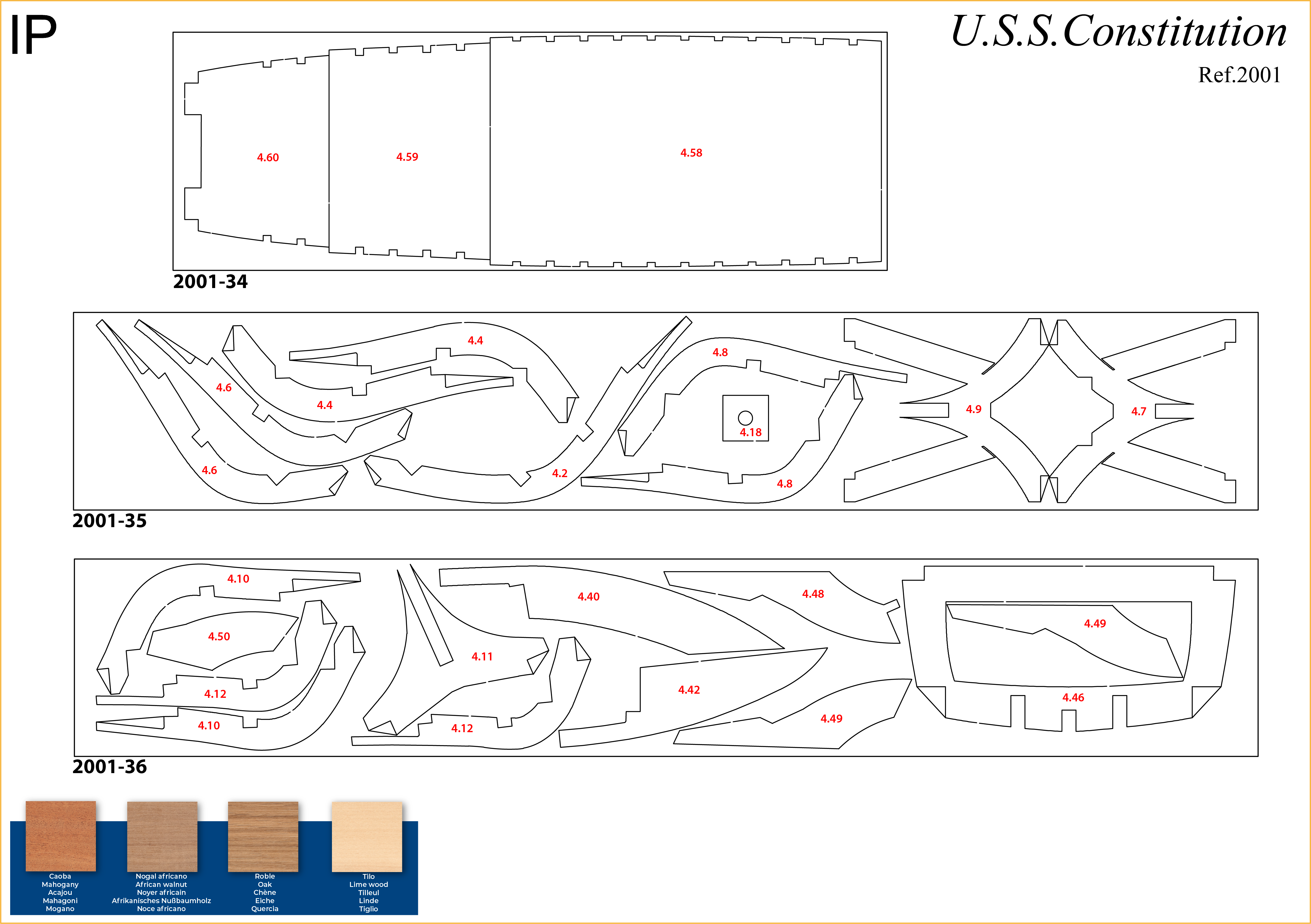
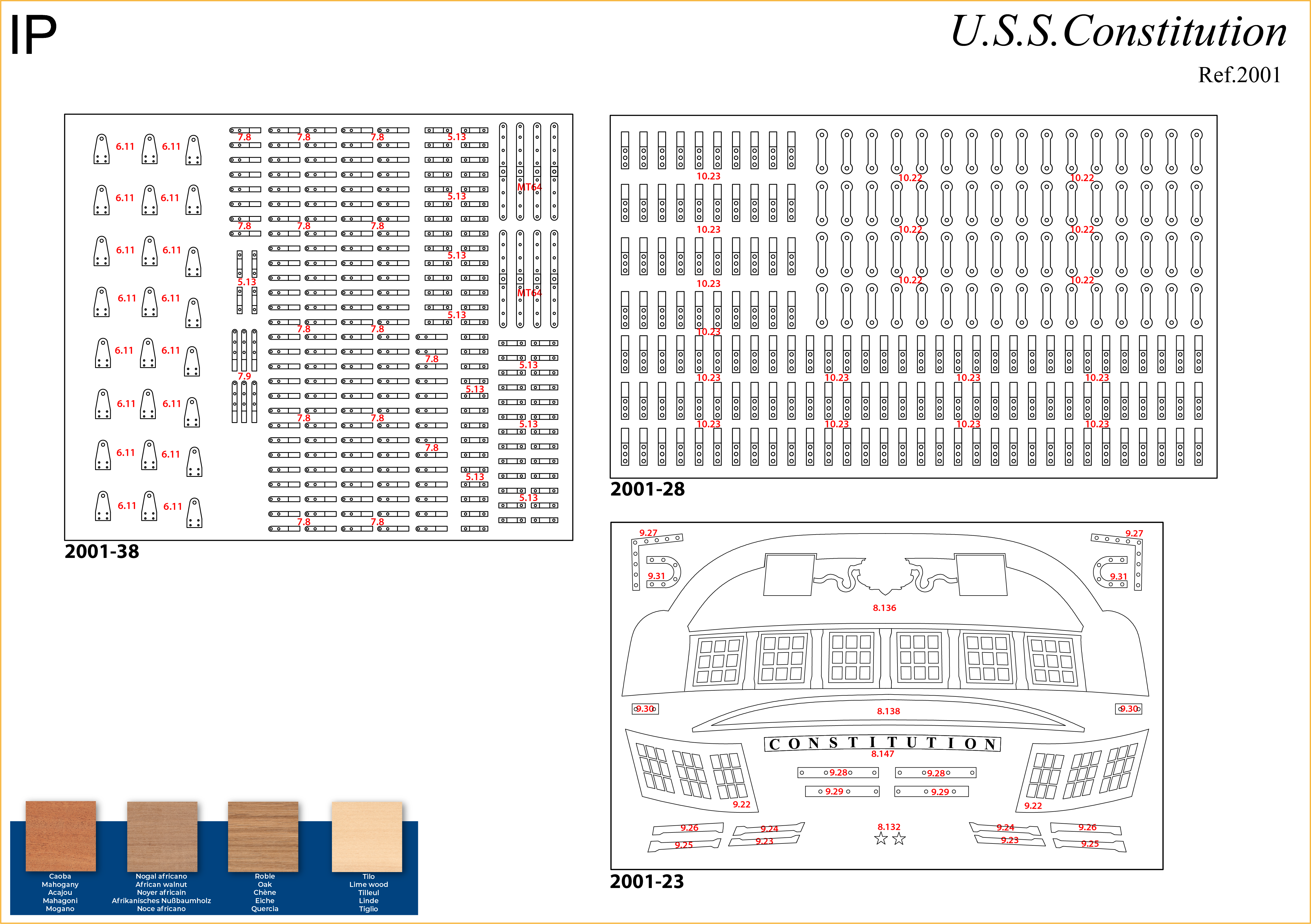
The IP sheets displayed below are drawings of laser-cut parts and photo-etched brass parts and will serve as a guide for identification of some parts.
Use the PARTS REFERENCE table to help locate the parts.
The PL-00 templates (printed at 1/1 scale) included in each pack will serve as a guide for building the frames.
Please check the list below to ensure you have all the tools required for building your wooden ship.
When removing a part, cut the ribs that join the part to the wooden plate with a cutter.
Remove the parts carefully so as not to break them.
Keep and store the parts in their frames. Only remove the parts you are working on in each step.
Extra support can be found on our forum or from the Expert Directory page of our website.
PARTS LIST
| Material | Quantity | |
| Boards 2001-34, 2001-35, 2001-36 | Wood | 3 |
| Sheets 2001-23, 2001-28, 2001-38 | Brass | 3 |
| Wooden Strips | ||
| 5 x 5 x 400 mm | Oak | 14 |
| 3 x 3 x 400 mm | Lime wood | 7 |
| 2 x 3 x 600 mm | Lime wood | 10 |
| 2 x 5 x 600 mm | Lime wood | 50 |
| Rod (ø 8 mm x 400 mm) | Mahogany | 1 |
| Templates | ||
| Assembly template PL-07 | 1 | |
| Assembly template PL-08 | 1 | |
| Other Parts | ||
| Nail (A) | 1000 |
Tools you will need: cutting mat, pencil, cutting knife, fine-grit sandpaper or sponge sandpaper, file, white wood glue, super glue (cyanoacrylate glue), masking tape, set square, hacksaw, sanding block, 30 cm steel ruler, clamps, drill, moulding scriber tool
PACK 04 IDENTIFICATION SHEETS
PARTS REFERENCE
PART NO. | IP-SHEET LOCATION | PART NO. | IP-SHEET LOCATION | PART NO. | IP-SHEET LOCATION |
| 4.1 | 2001-17 | 4.19 | 2001-12 | 4.49 | 2001-36 |
| 4.2 | 2001-18 + 2001-35 | 4.27 | 2001-11 | 4.50 | 2001-6 + 2001-36 |
| 4.3 | 2001-18 | 4.37 | 2001-11 | 4.51 | 2001-6 + 2001-8 |
| 4.4 | 2001-35 | 4.39 | 2001-10 | 4.52 | 2001-2 |
| 4.5 | 2001-18 | 4.40 | 2001-2 + 2001-36 | 4.53 | 2001-6 |
| 4.6 | 2001-35 | 4.41 | 2001-2 + 2001-10 | 4.54 | 2001-15 |
| 4.7 | 2001-35 | 4.42 | 2001-2 + 2001-36 | 4.55 | 2001-15 |
| 4.8 | 2001-35 | 4.43 | 2001-2 + 2001-19 | 4.56 | 2001-8 |
| 4.9 | 2001-35 | 4.44 | 2001-1 | 4.57 | 2001-8 |
| 4.10 | 2001-36 | 4.45 | 2001-1 | 4.58 | 2001-34 |
| 4.11 | 2001-36 | 4.46 | 2001-36 | 4.59 | 2001-34 |
| 4.12 | 2001-36 | 4.47 | 2001-1 | 4.60 | 2001-34 |
| 4.18 | 2001-35 | 4.48 | 2001-16 + 2001-36 | 4.64 | 2001-5 |
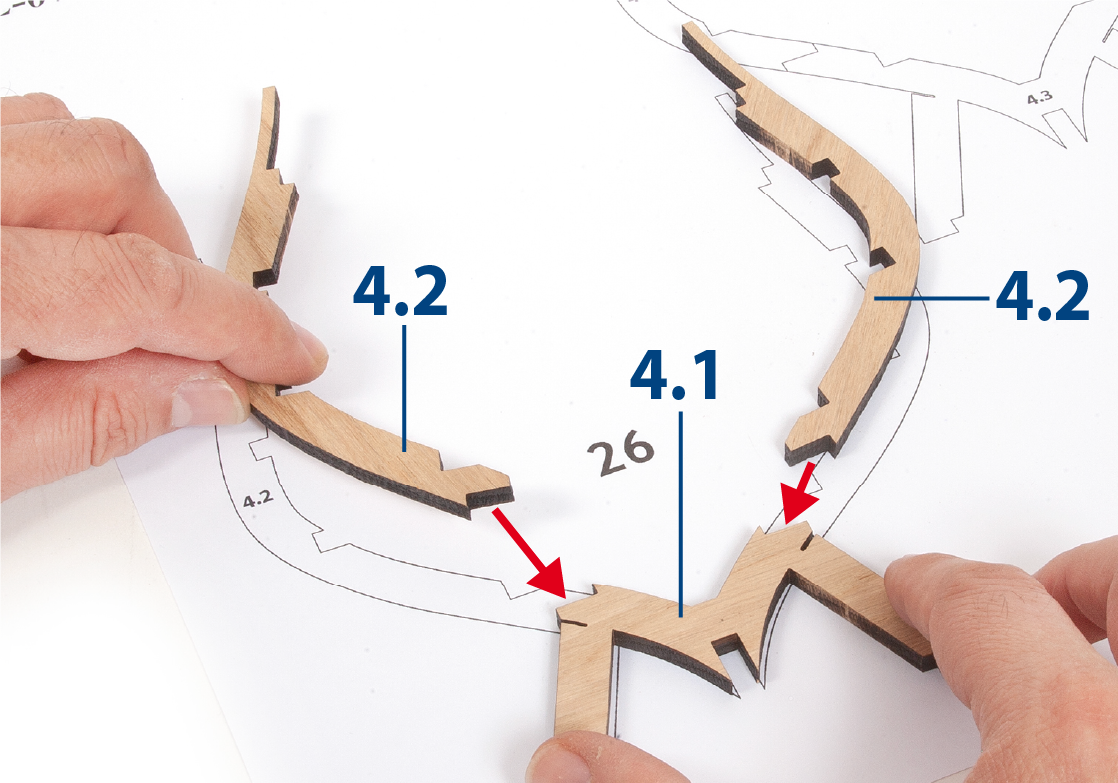
ステップ 1
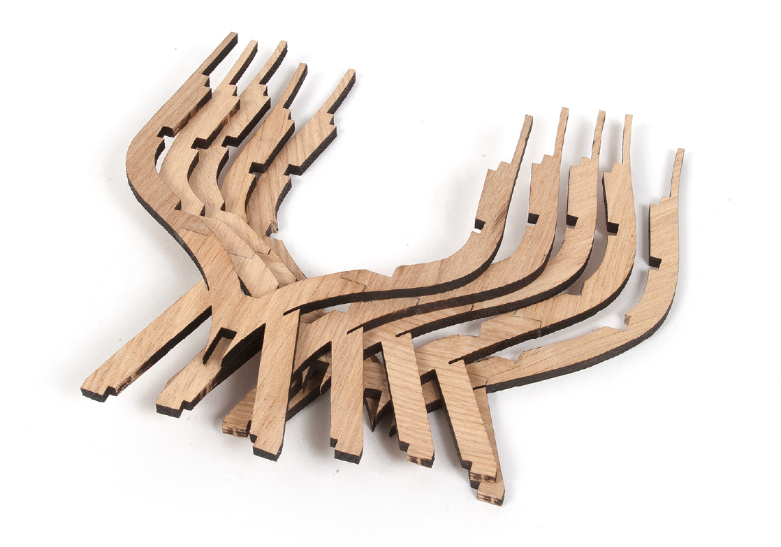
Identify the pieces that make up frames 26 to 31.
ステップ 2
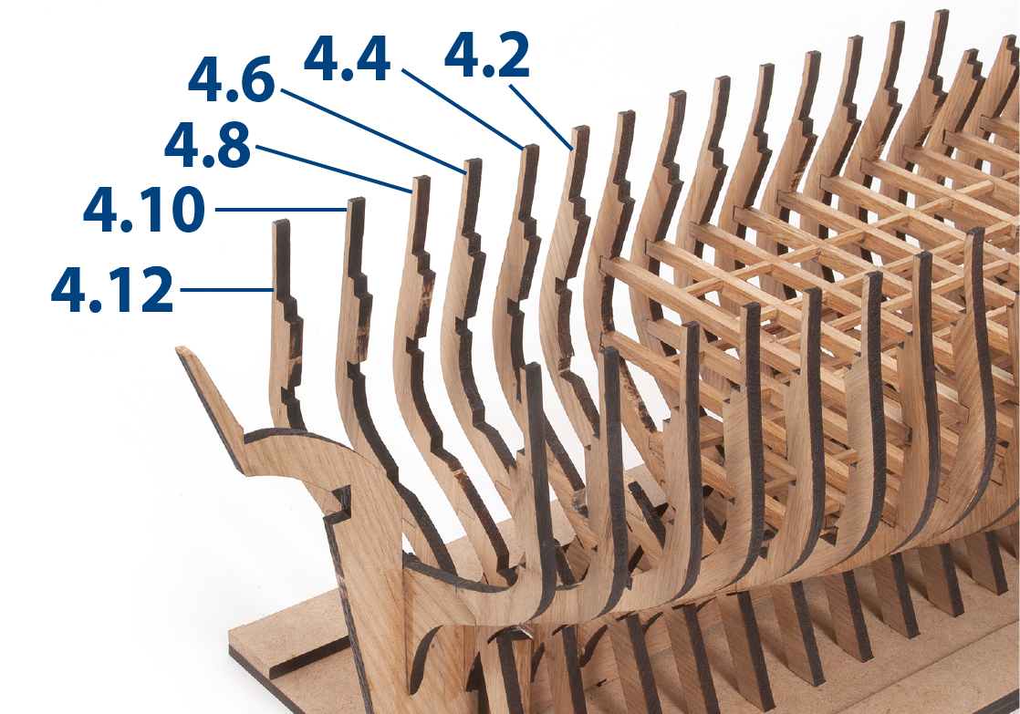
Construct frames 26 to 31 using the templates provided.
ステップ 3
Insert and glue the frames 26 to 31 in their final positions. Make sure that they are correctly positioned.
ステップ 4
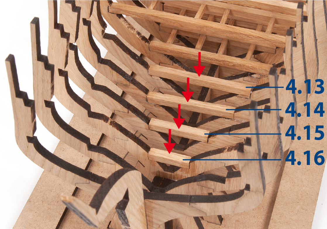
Cut to size and glue pieces 4.13 to 4.16 (5 x 5mm), as shown in the picture.
ステップ 5
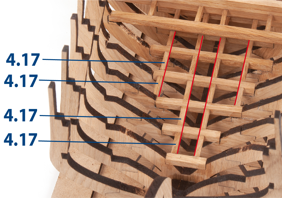
Cut to size and glue parts 4.17 (3 x 3 mm) as shown in the picture.
ステップ 6
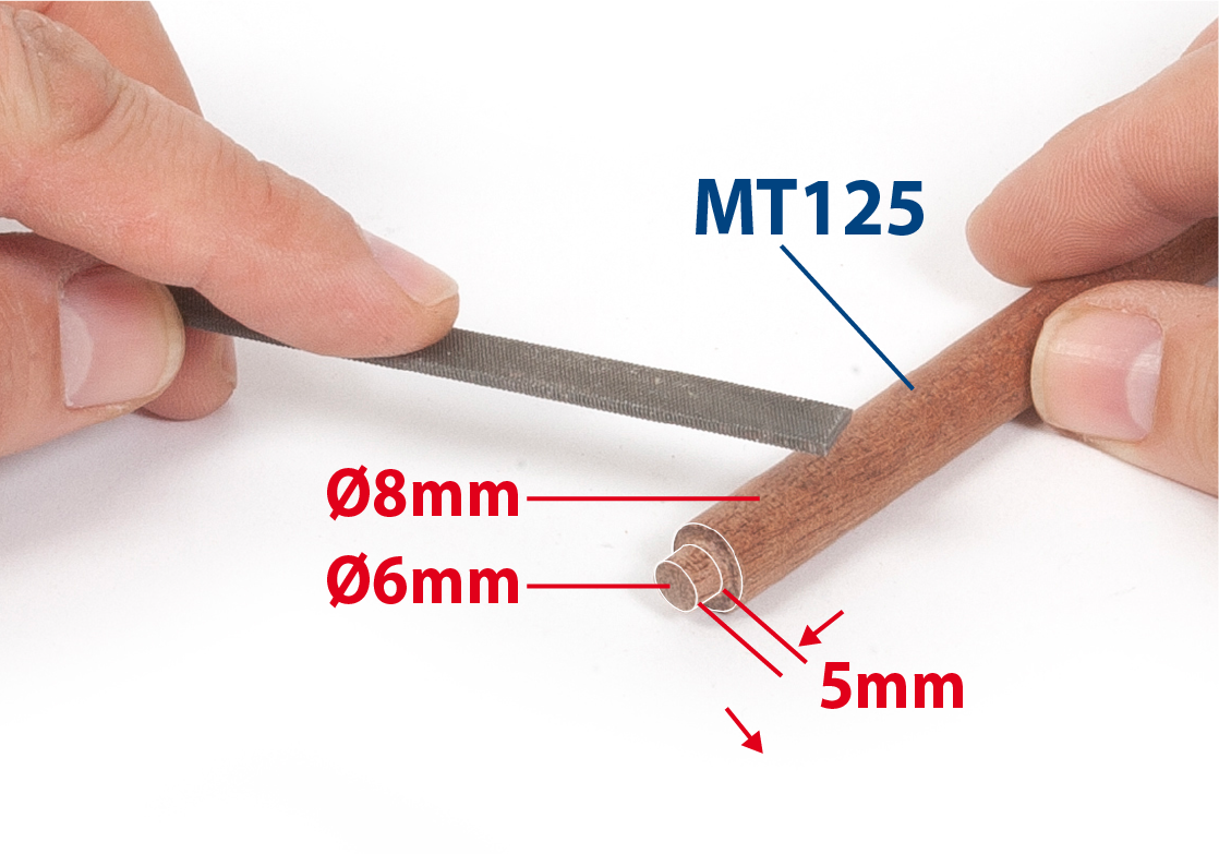
Take a ø8mm rod and at one end reduce its diameter to ø6mm.
ステップ 7
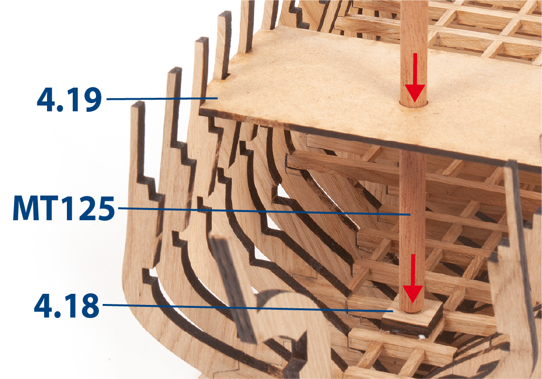
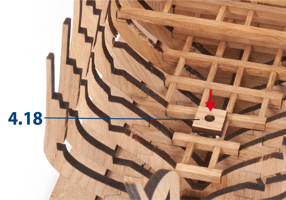
Use part 4.19 to align part 4.18 with part MT125.
ステップ 8
Then glue part 4.18 permanently.
ステップ 9
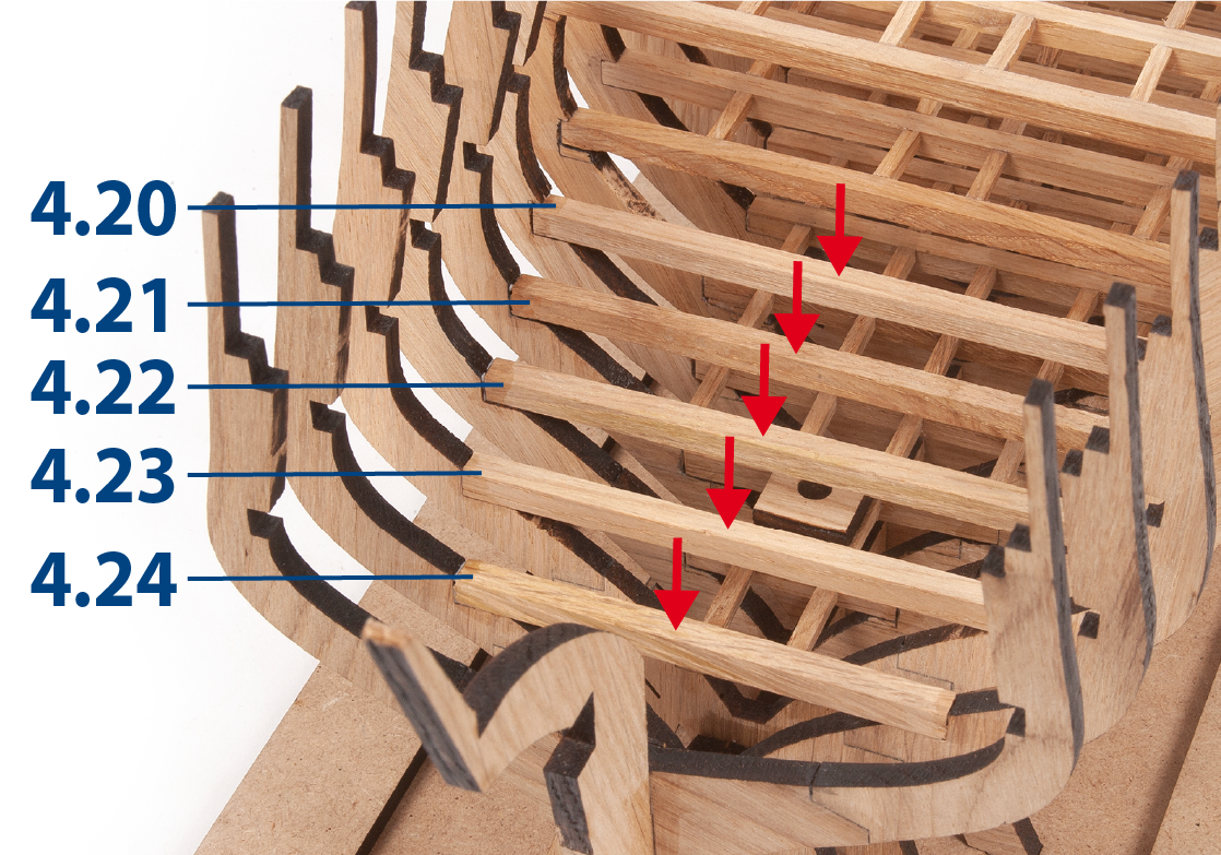
Cut parts 4.20 to 4.24 (5 x 5mm) to length and glue them in place.
ステップ 10
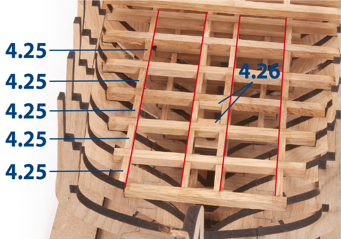
Cut to length and glue parts 4.25 and 4.26 (3 x 3 mm) in place.
ステップ 11
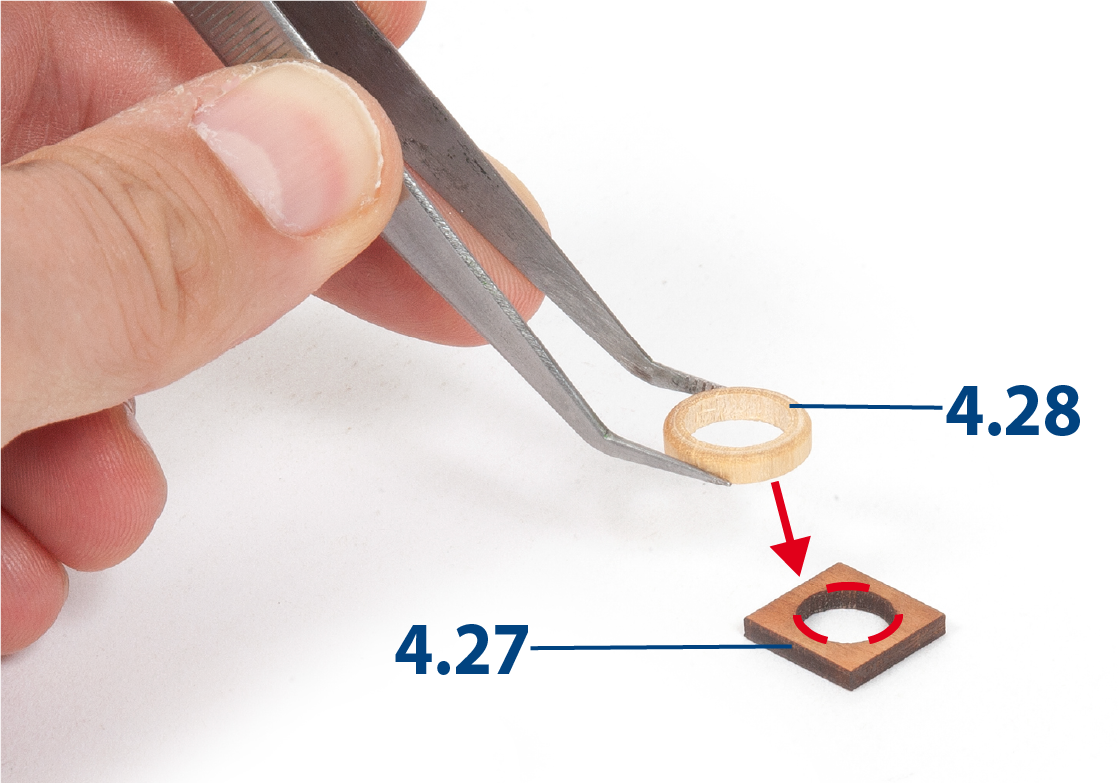
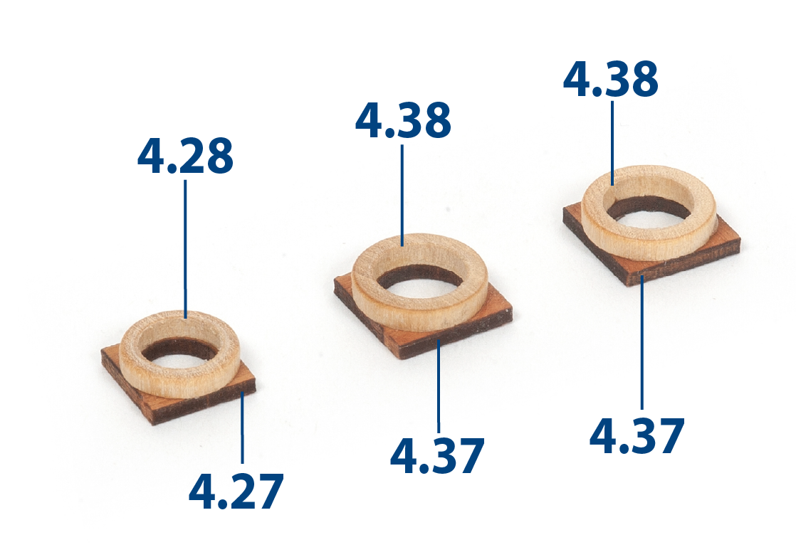
Glue a part 4.28 centred on part 4.27.
Check that you have the correct ring by test-fitting it onto the ø8mm mast MT125.
ステップ 12
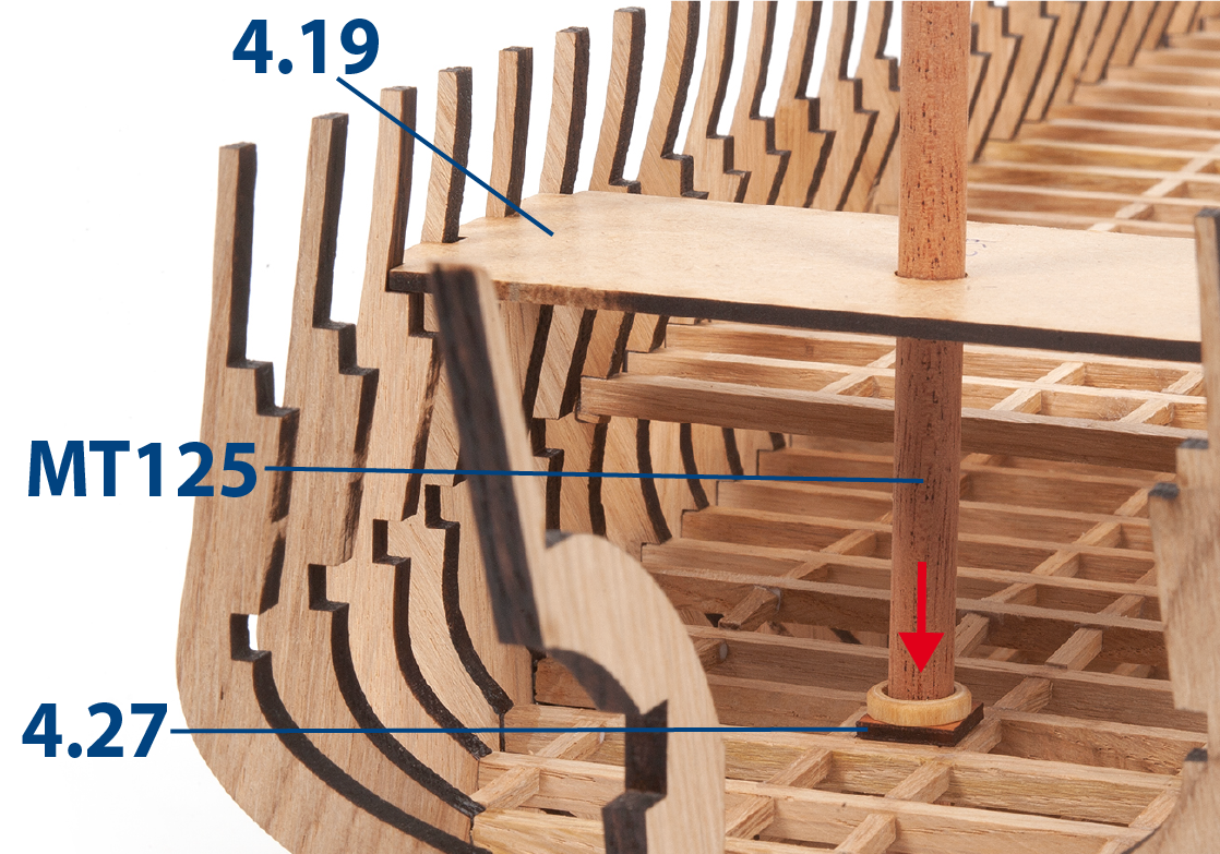
Present the centring assembly with parts MT125 and 4.19.
ステップ 13
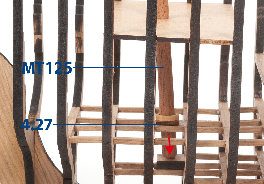
Fit and glue parts 4.27 and 4.28.
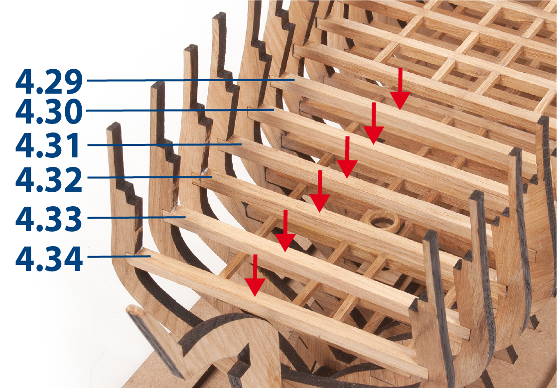
ステップ 14
Cut to length and glue parts 4.29 to 4.34 (5 x 5mm) to the corresponding frames.
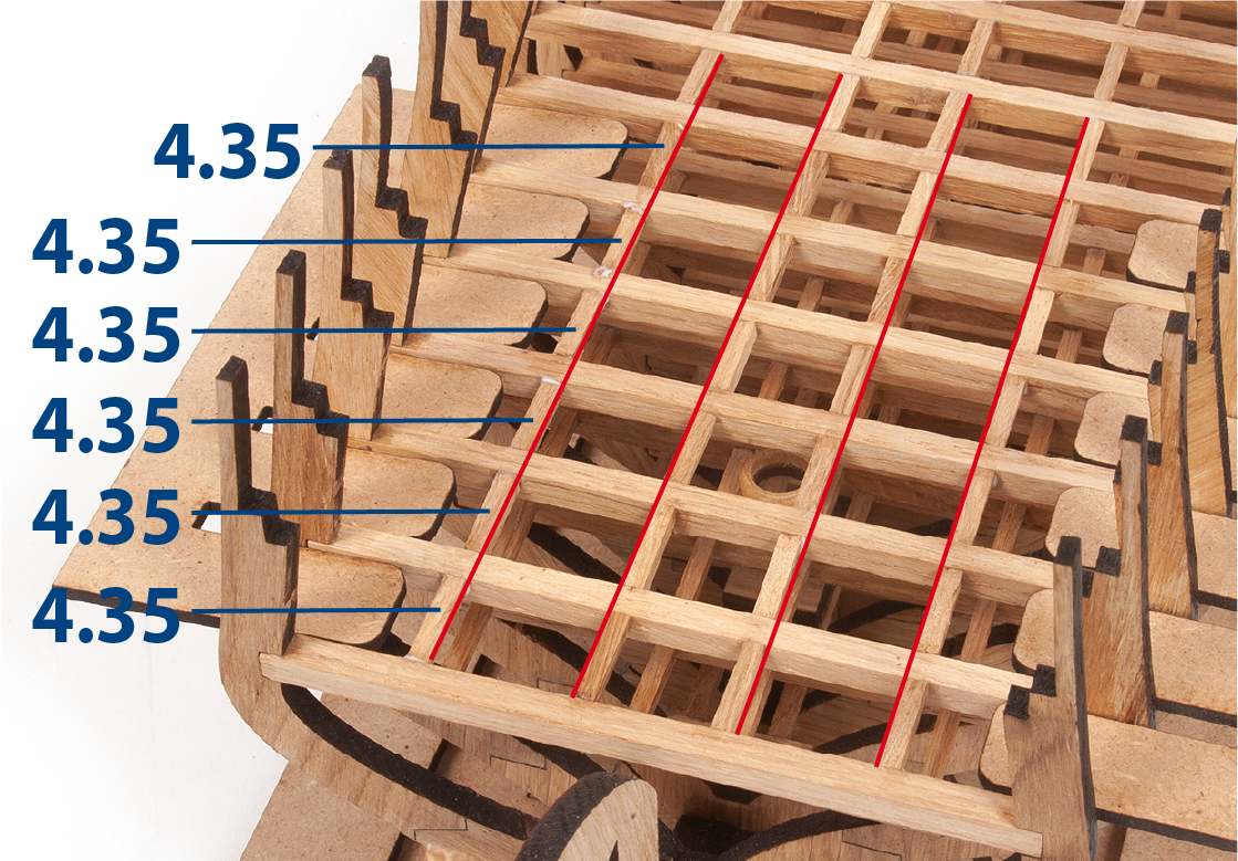
ステップ 15
Cut to length and glue the pieces 4.35 (3 x 3mm).
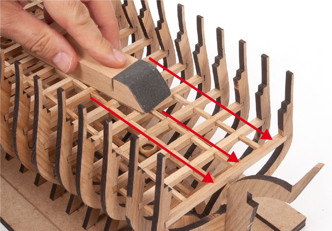
ステップ 16
Sand the top of the parts to even their surface.
ステップ 1
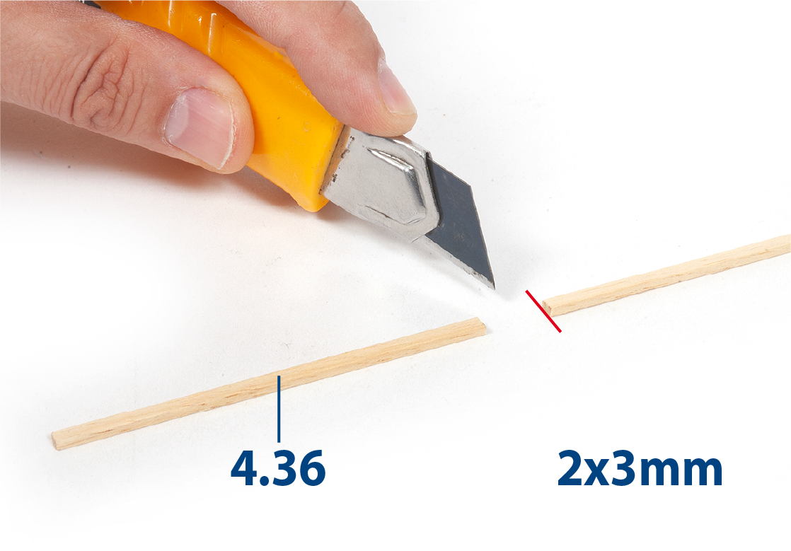
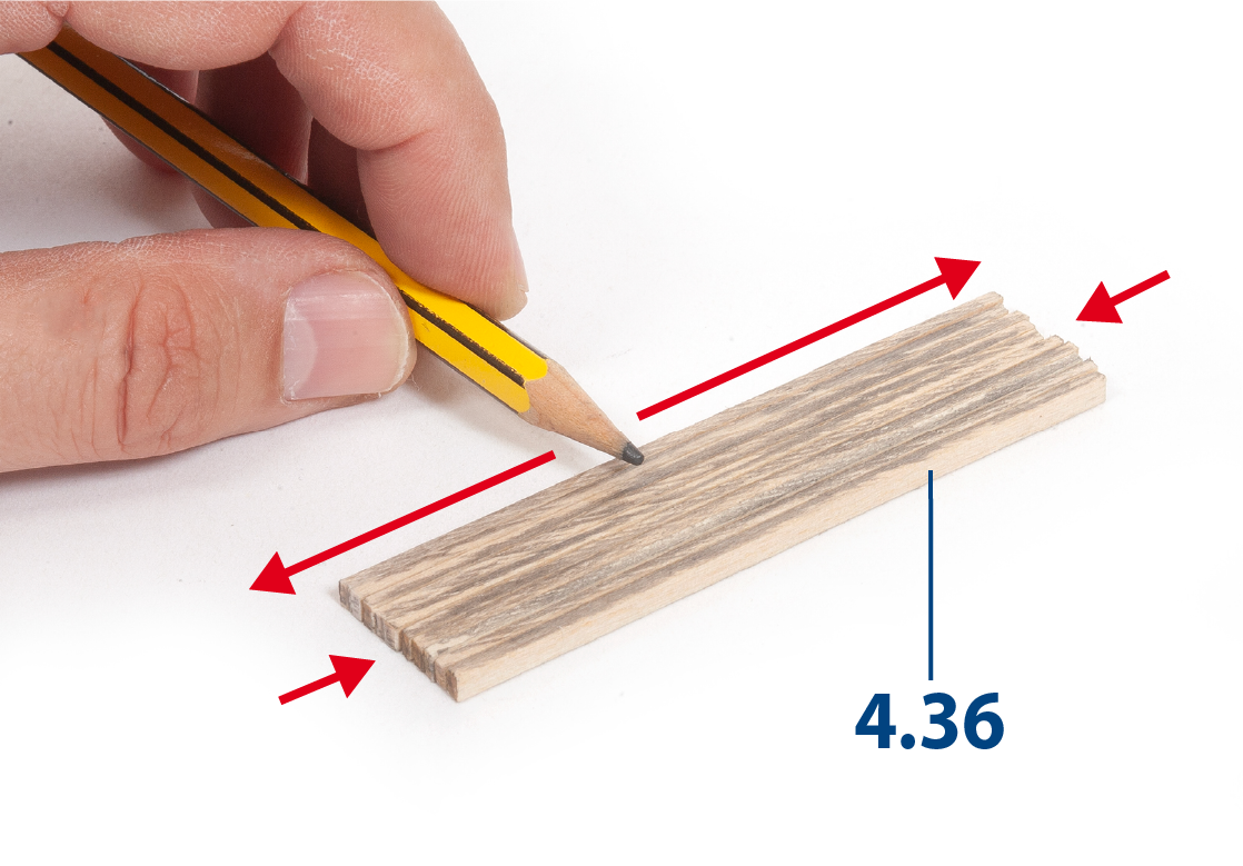
Before proceeding, look at the images in steps 2–11 for an overview of cutting and fitting parts 4.36.
Cut parts 4.36 to length. Make sure the cut is as straight as possible.
ステップ 2
Use a pencil to shade the four edges of each piece.
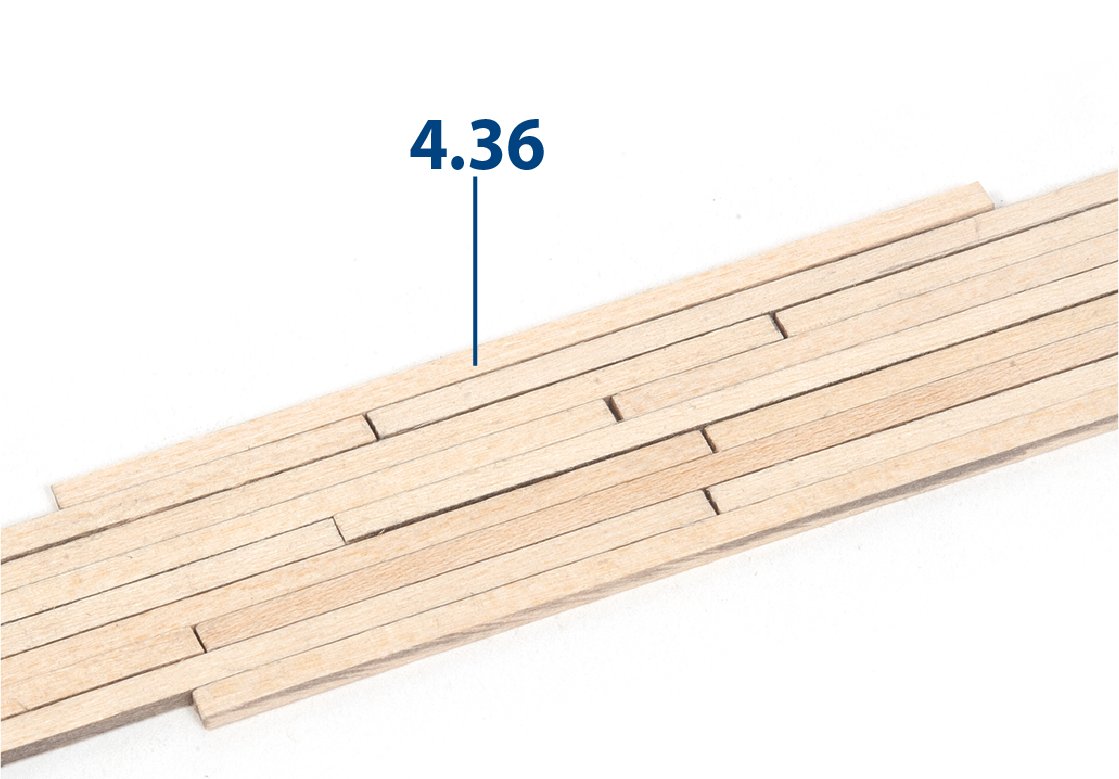
ステップ 3
Lay out the parts as shown in the picture to check the joints.
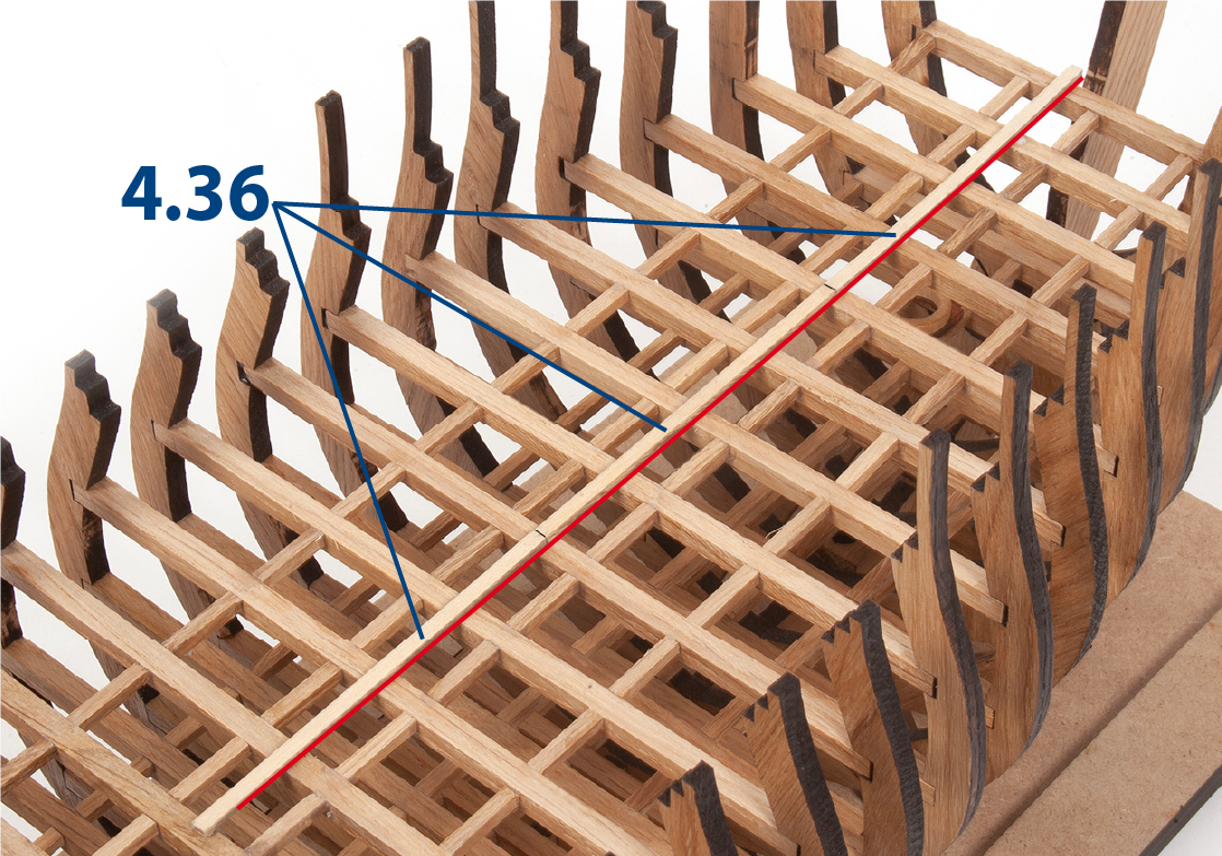
ステップ 4
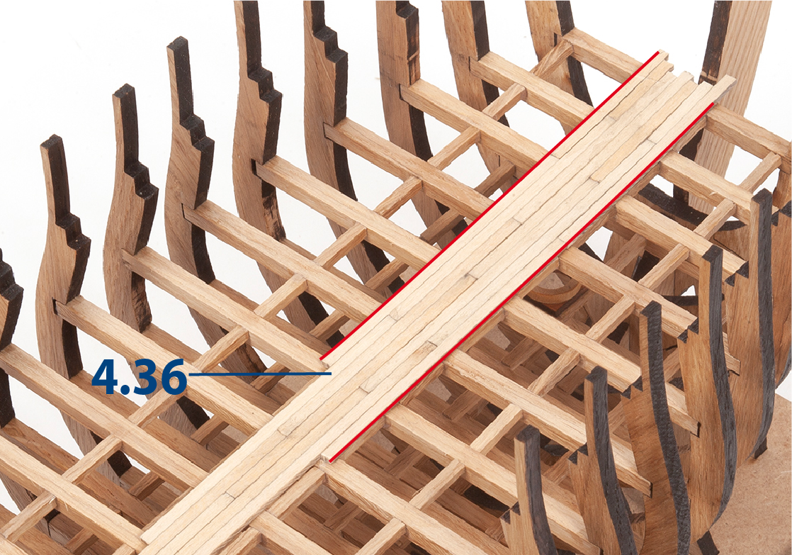
Glue three pieces 4.36 centred on the structure so that their joints coincide on a batten.
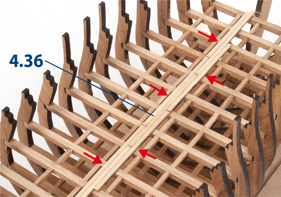
ステップ 5
Continue gluing pieces 4.36 to complete the length of the structure. It is important that the pieces are glued close together to achieve a good finish.
ステップ 6
See in the picture how the parts should look once they have been fixed.
ステップ 7
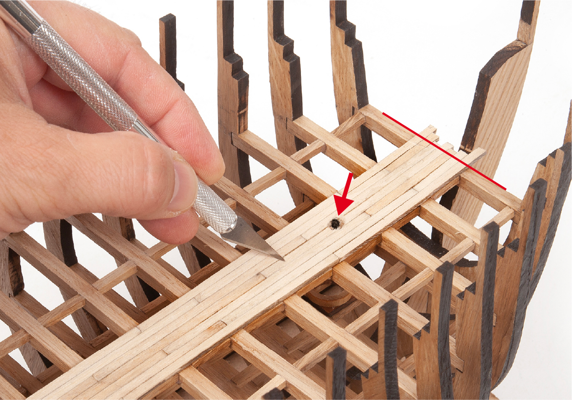
Complete seven lines of parts 4.36. Use a cutting knife to cut out the pieces that cover the path of the mast.
ステップ 8
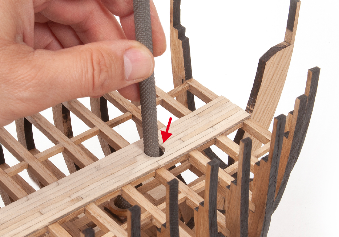
Use a file to adjust the mast hole.
ステップ 9
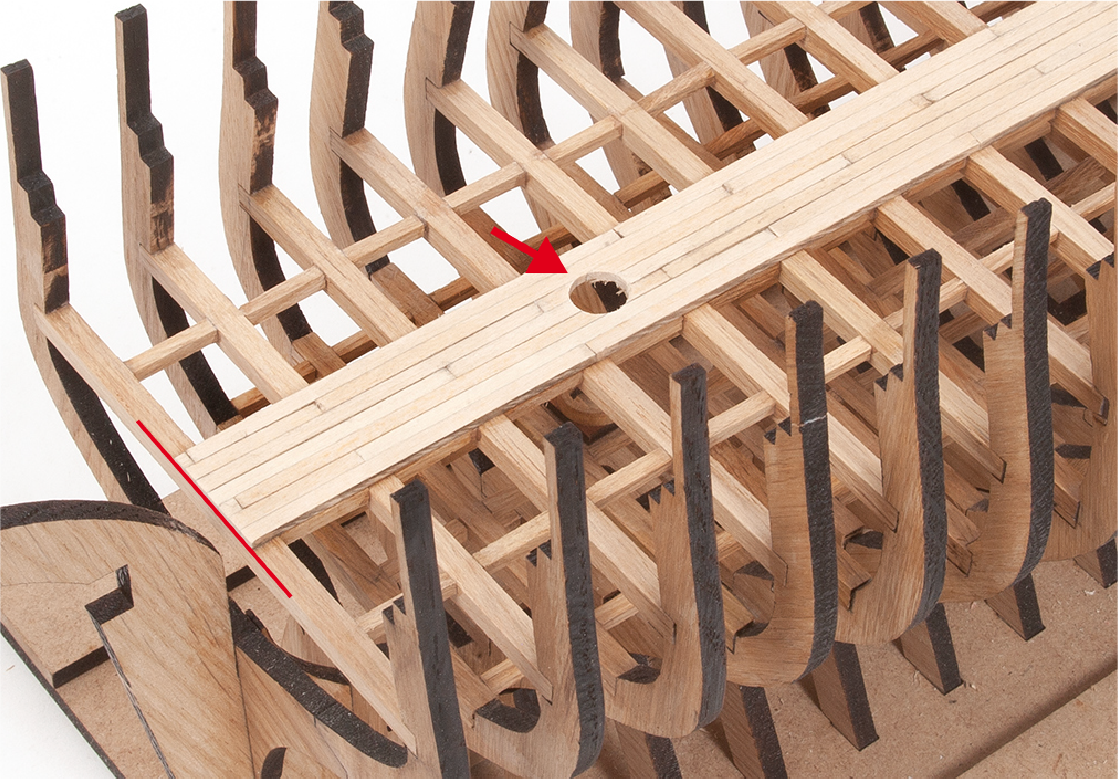
See in the picture how the aft part will look.
ステップ 10
Use a sand block to even out the surfaces of the parts.
ステップ 11
Note how the hull structure should look.
ステップ 1
In the central part of the structure, glue the parts 4.36.
ステップ 2
Even out the surfaces with a sanding block.
ステップ 3
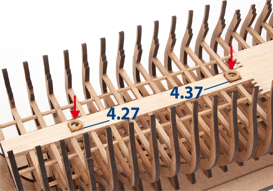
Glue parts 4.28 and 4.38 onto parts 4.27 and 4.37.
ステップ 4
Check the fit of the parts.
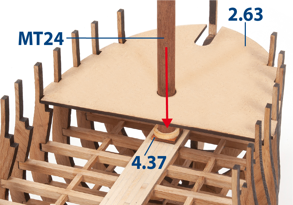
ステップ 5
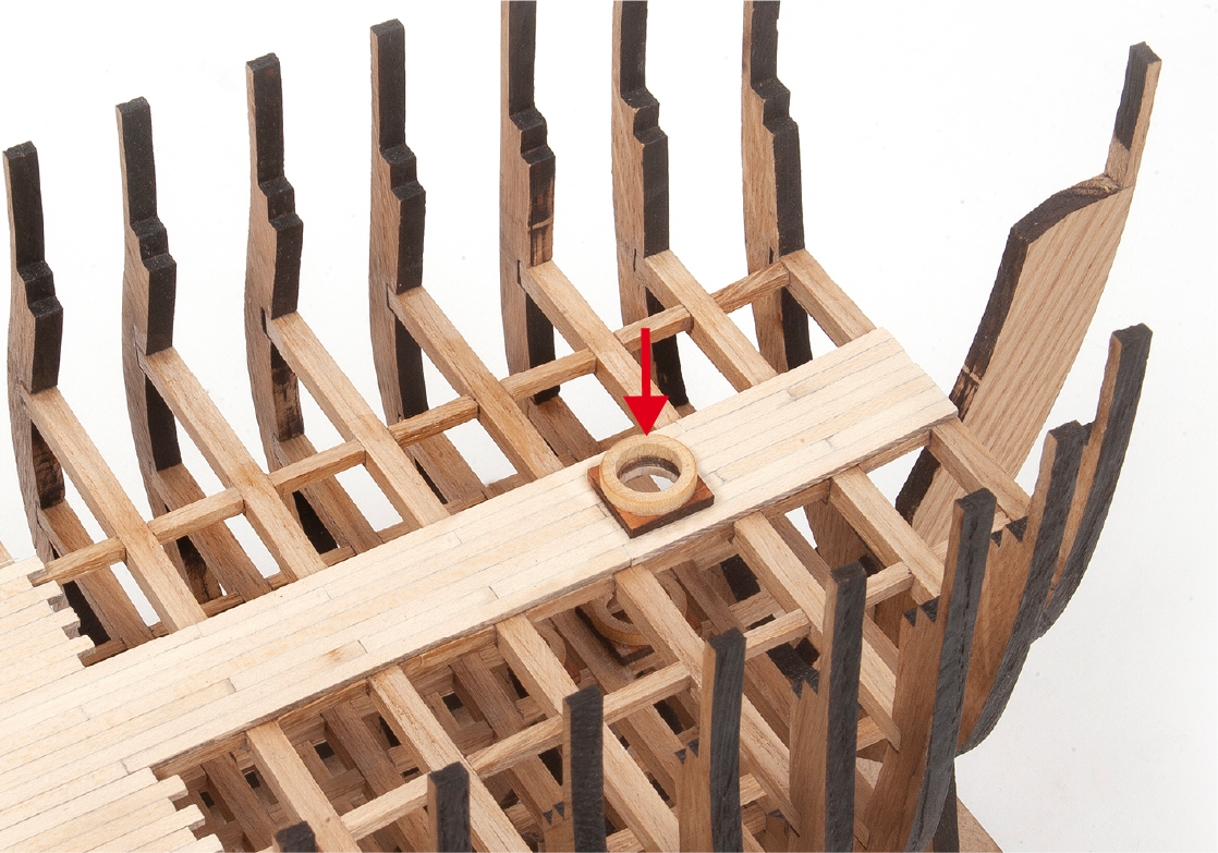
Glue the parts centred over the holes in the masts.
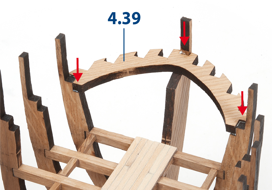
ステップ 7
Fit and glue the parts 4.40.
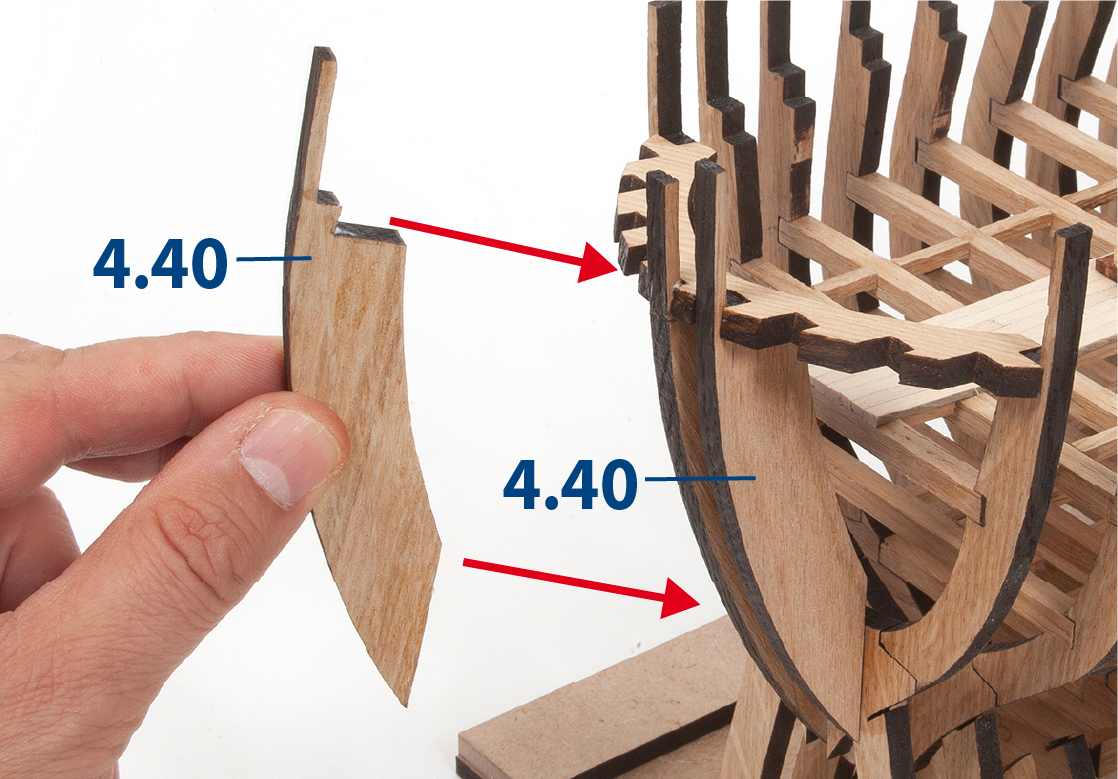
ステップ 8
Fit and glue the parts 4.41.
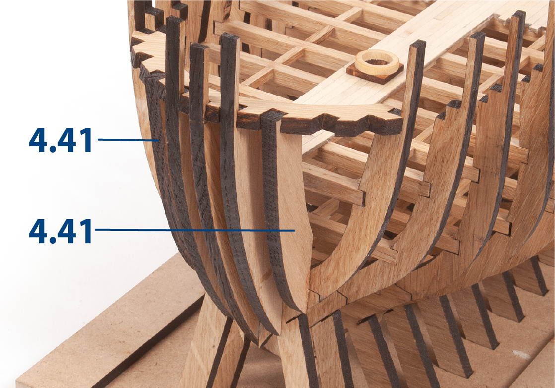
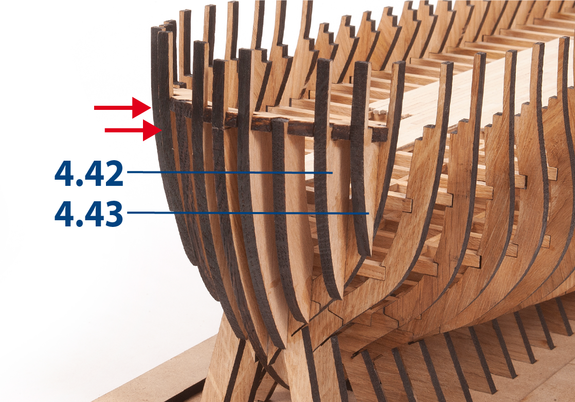
ステップ 9
Fit and glue parts 4.42 and 4.43.
ステップ 10
Glue the pieces 4.44 and 4.45 together as shown in the picture.
ステップ 11
Check the fit of the assembly to the structure.
ステップ 12
Glue the assembly together permanently.
ステップ 13
Insert parts 1.31 to align the frames. Glue part 4.46.
ステップ 1
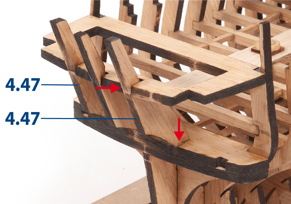
Glue the parts 4.47.
ステップ 2
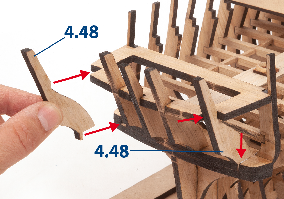
Glue the parts 4.48.
ステップ 3
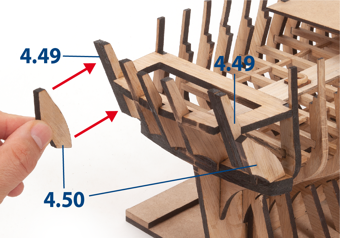
Glue parts 4.49 and 4.50.
ステップ 4
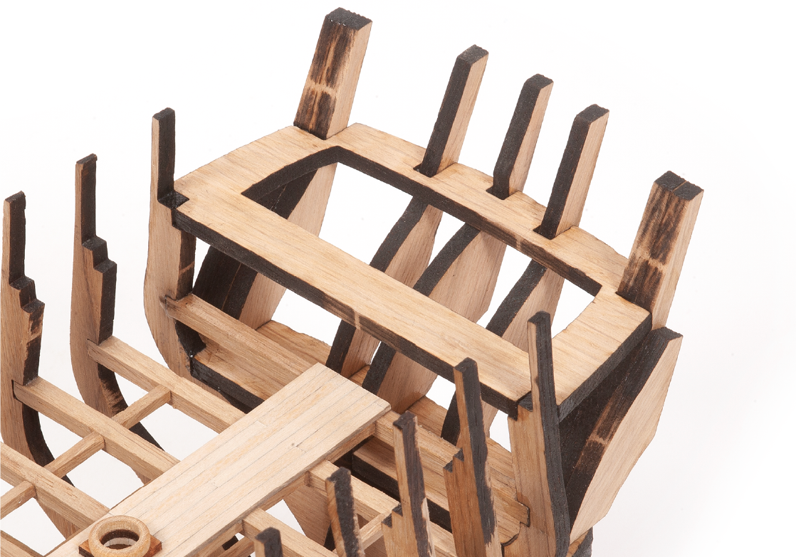
This picture shows the parts in place.
ステップ 5
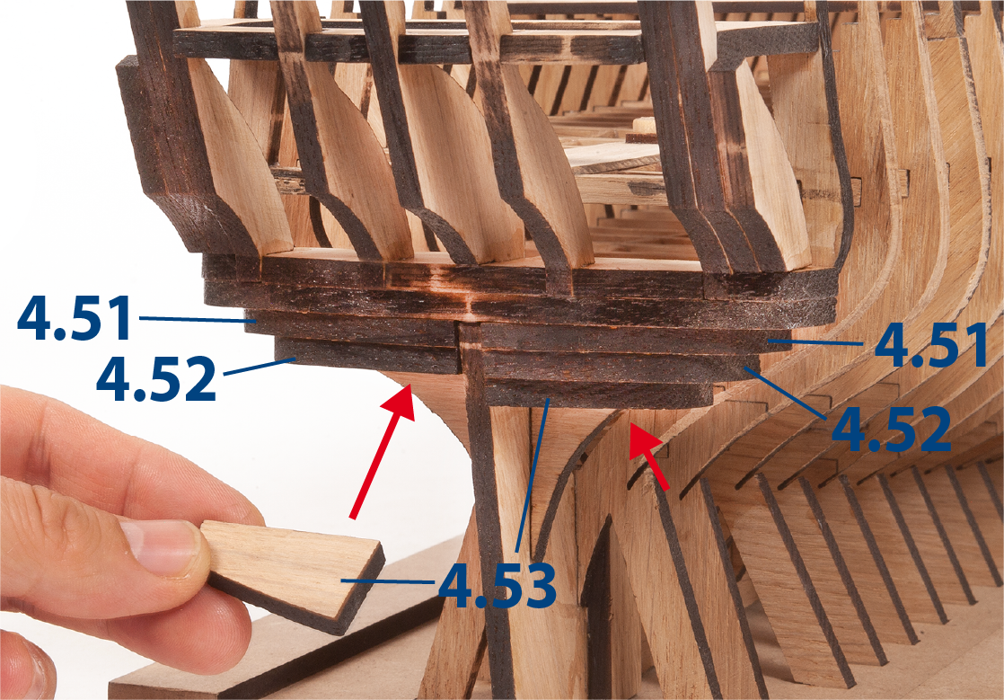
Glue parts 4.51 to 4.53.
ステップ 6
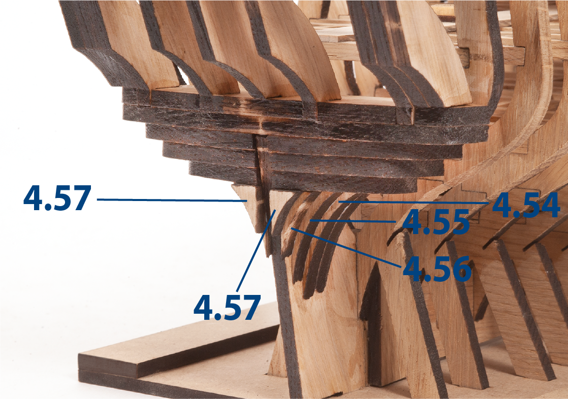
Glue parts 4.54 to 4.57 to the structure.
ステップ 7
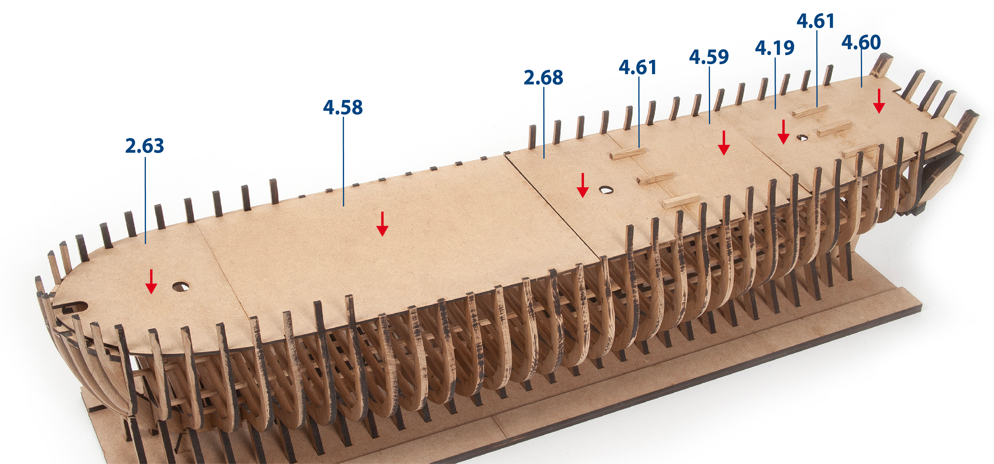
Insert, without gluing, parts 2.63 and 2.68, 4.19, 4.58, 4.59 and 4.60 into the structure to immobilise the frames. Glue pieces 4.61 (5 x 5 x 30 mm) shown in the picture to join the decks.
ステップ 8
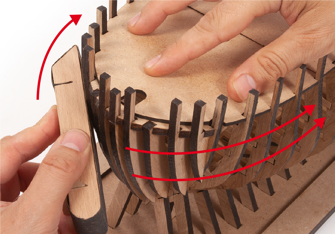
Read through steps 9 to 11 before you start sanding.
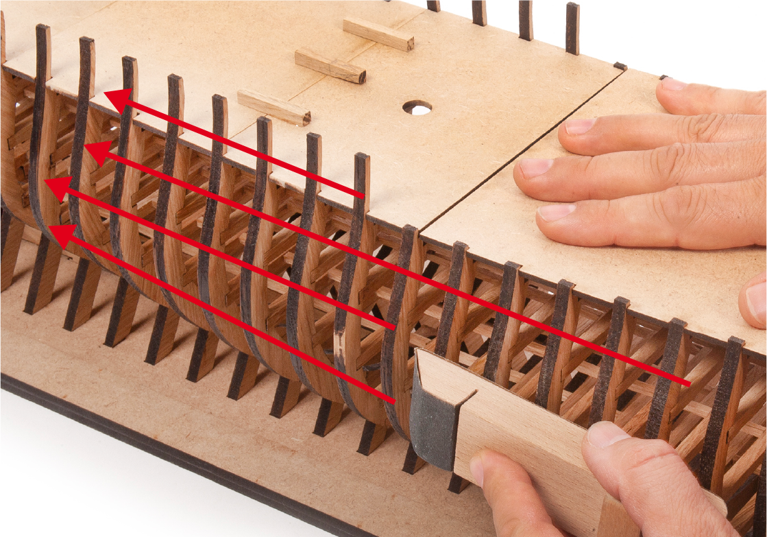
Start sanding the frames with a sanding block and medium grit sandpaper. It is important that you sand while holding the decks with one hand to immobilise the frames and prevent them from breaking. You should sand smoothly and progressively, smoothing the edges of the frames, without losing their original profile.
ステップ 9
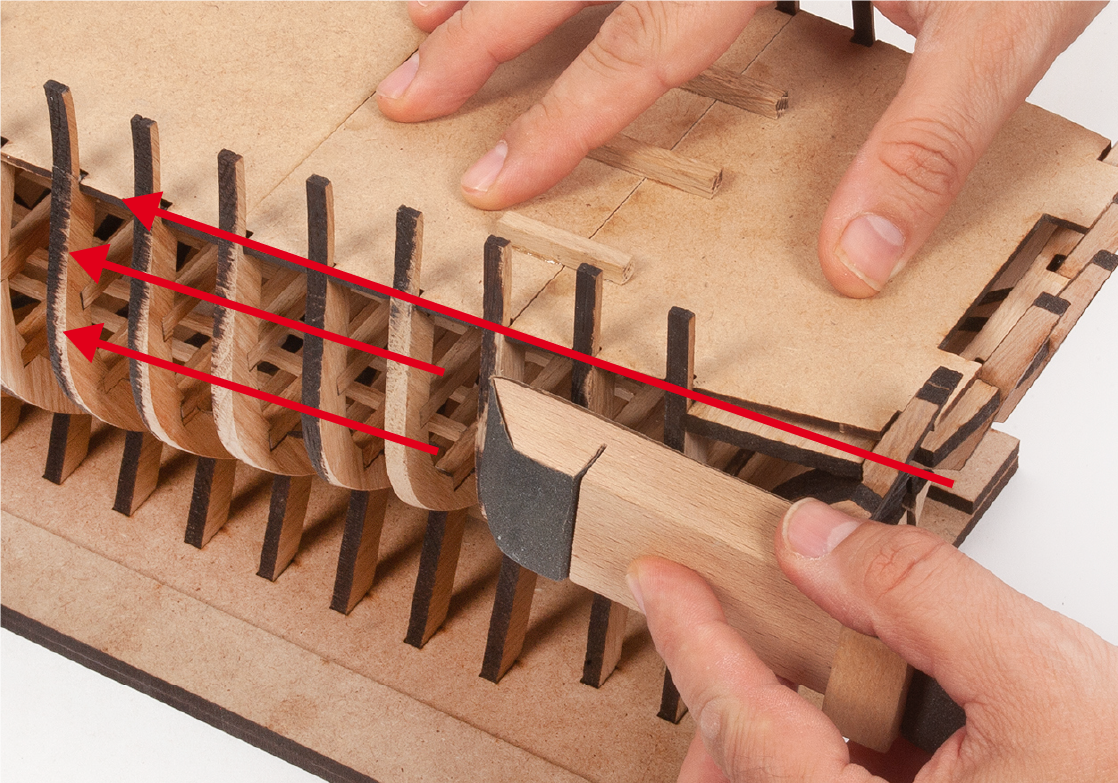
Sanding should start from the front of the hull and working towards the rear.
ステップ 10
You should sand in one direction only, i.e. press down on the sanding block when moving forward and loosen it when moving backwards to avoid snagging on a frame.
ステップ 11
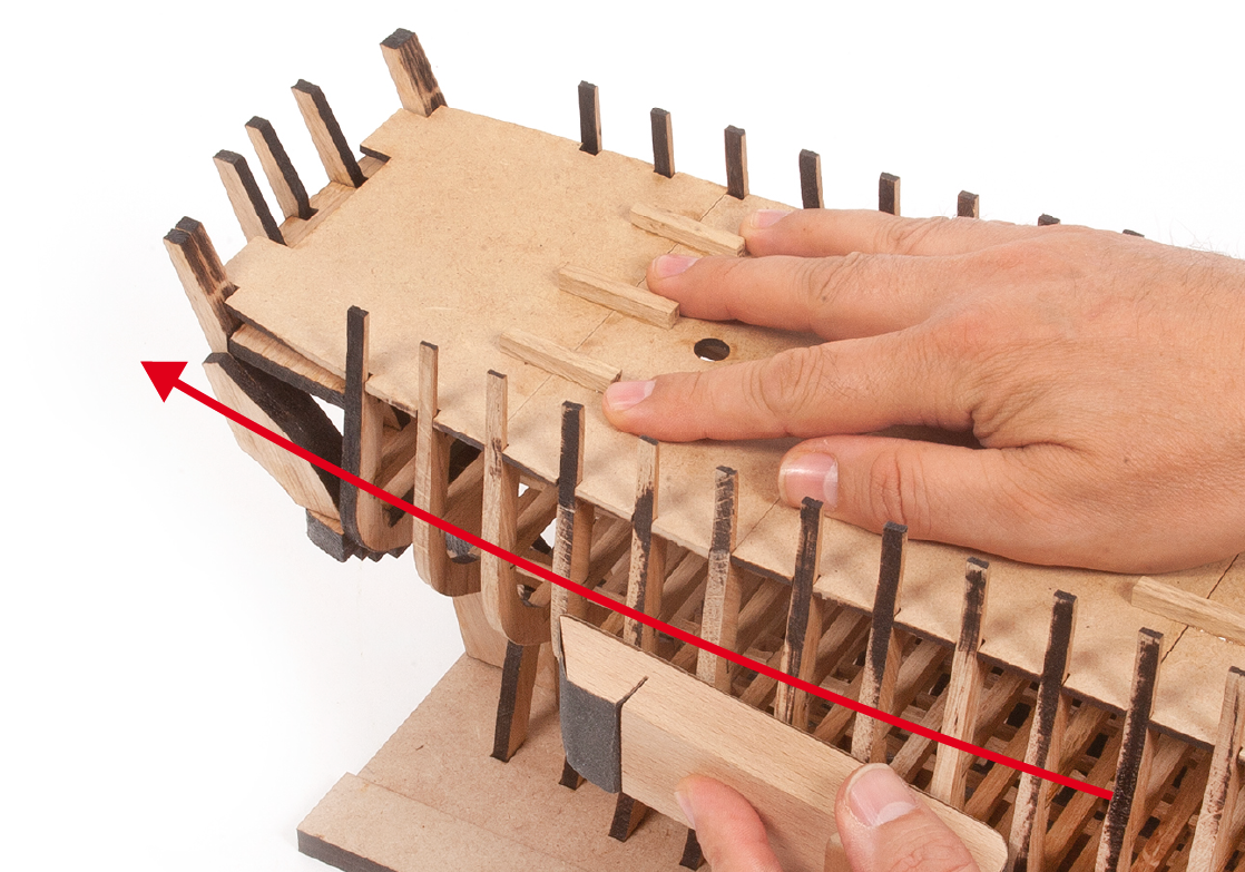
Then sand from the rear towards the front.
ステップ 1
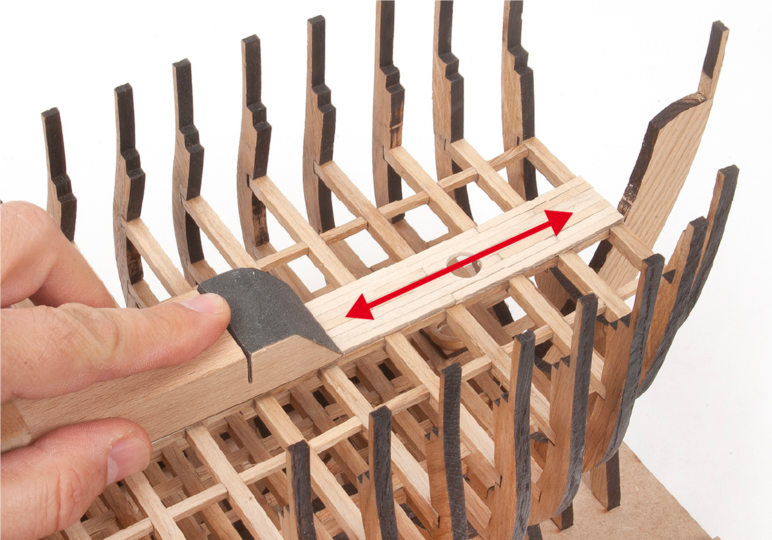
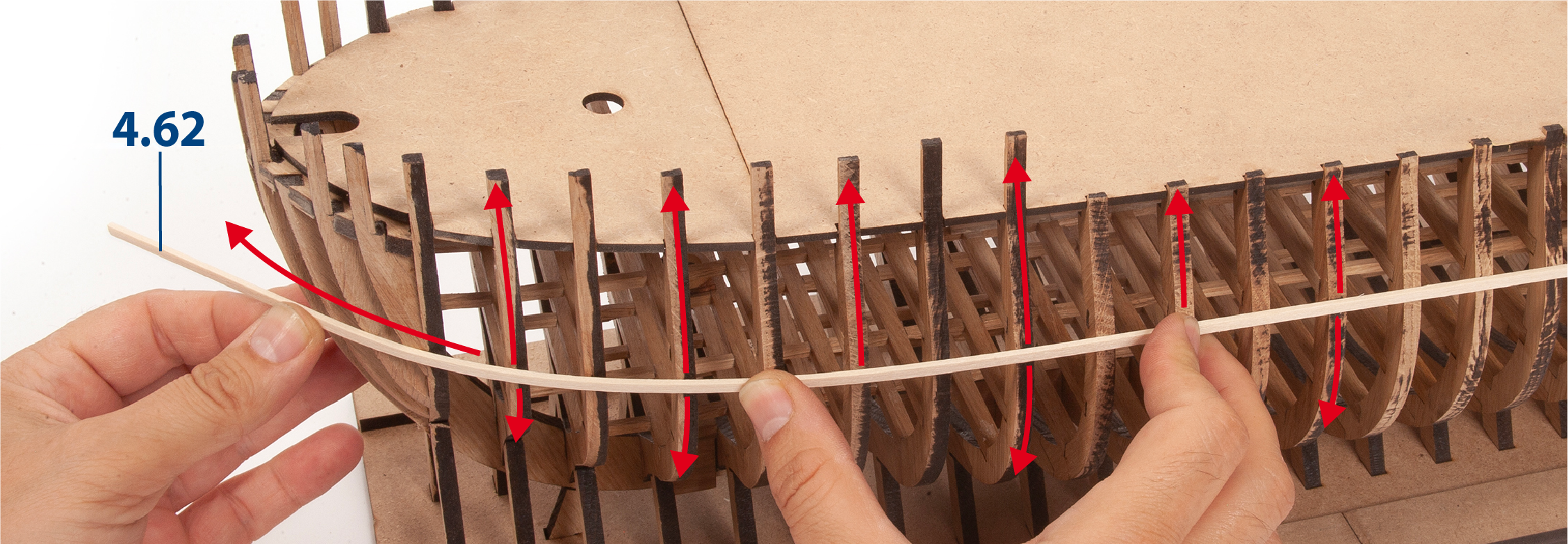
Use part 4.62 (2 x 5 x 600 mm) to check the sanding progress. Hold the batten close to the frames and slide it up and down to see where it touches and where it does not, so that you can make any necessary adjustments.
ステップ 2
Use masking tape to secure the hull structure to the mounting base.
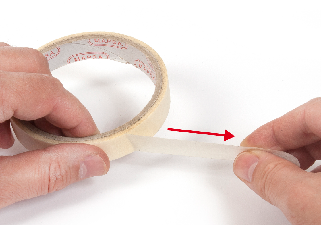
ステップ 3
Apply tape at several points to ensure that it is firm and immobile.
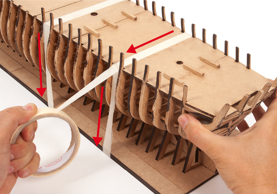
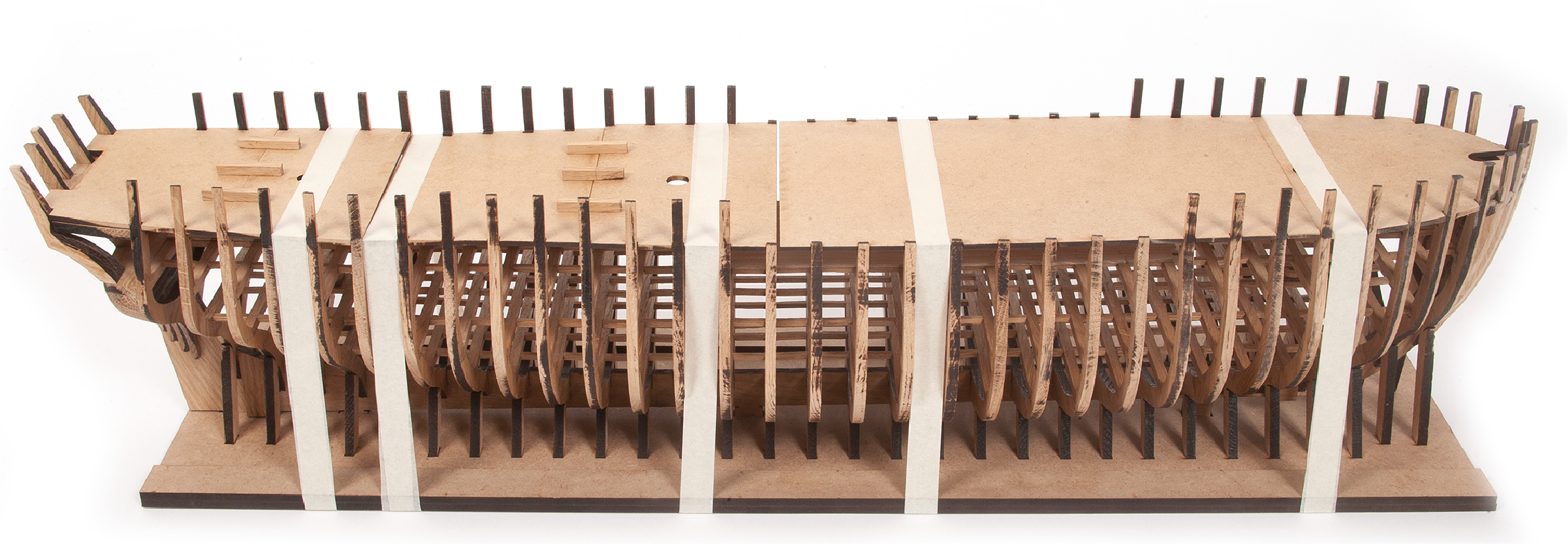
ステップ 4
See the picture showing the fixing points of the tape.
ステップ 5
It is advisable to place the hull on foam or fabric to cushion the movement and protect the frames from breaking.
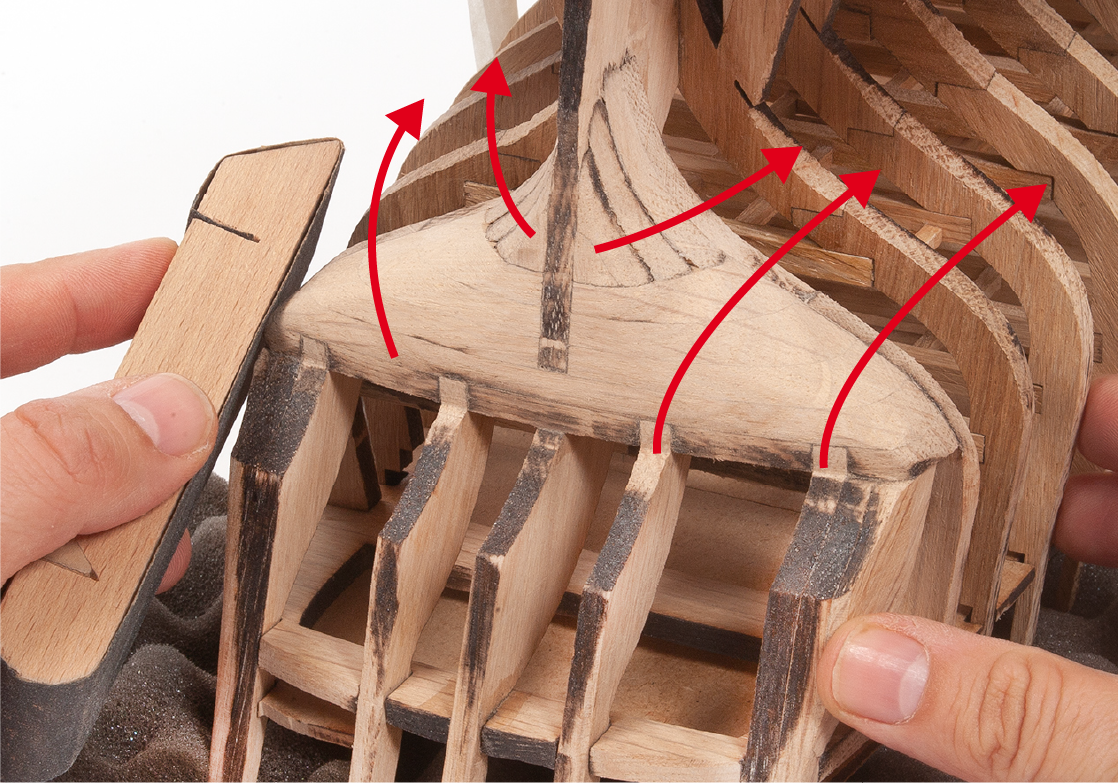
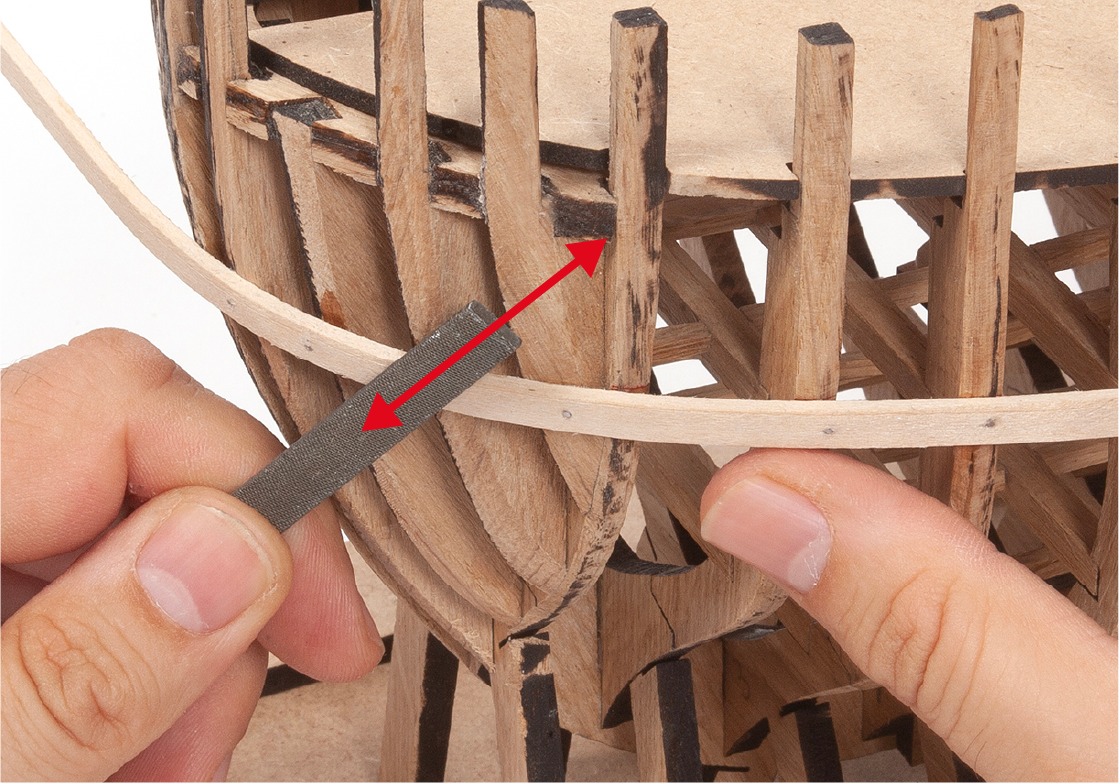
ステップ 6
Use a half-round file to complete the sanding on the curved areas at the rear of the hull.

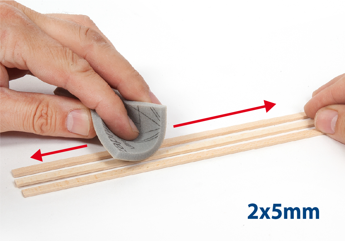
ステップ 7
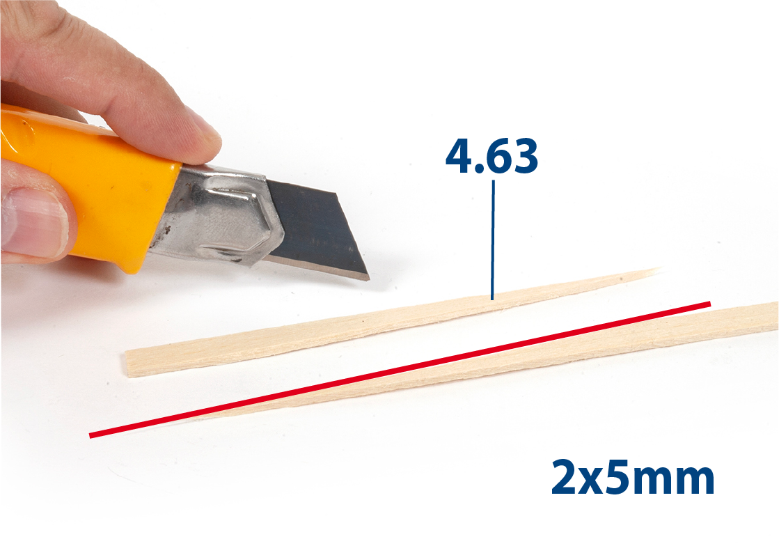
Take three or four 2x5mm strips and sand them.
ステップ 8
This model boat is designed to leave the underside of the hull unlined so that the interior of the hull structure can be seen.
If you wish to line the underside, do not apply glue – go straight to stage 17 step 5. Do not plank this section of the stern. This will be planked with mahogany in pack 6. See the pack 6 instructions in the Download Centre to find out more.
If you do not wish to line the underside, apply super glue as shown.
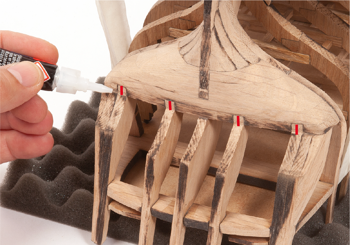
ステップ 9
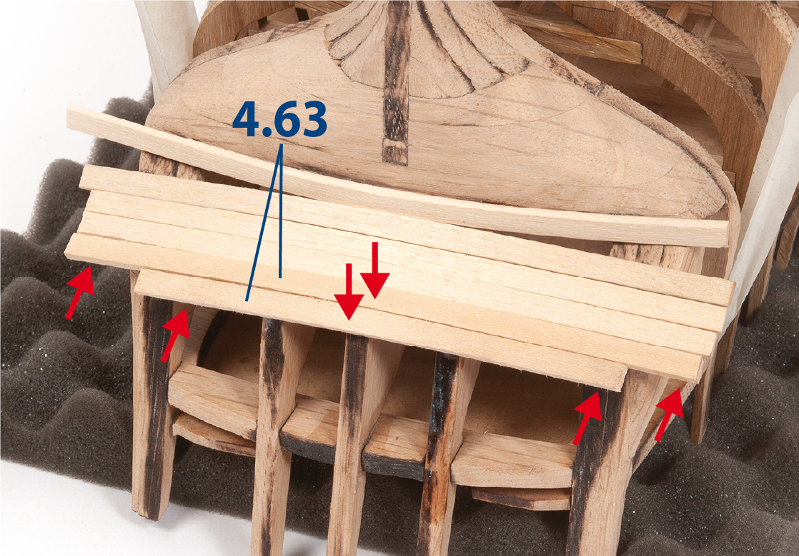
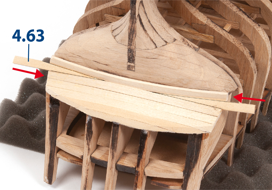
Glue a 4.63 (2 x 5 x 140 mm) piece in place.
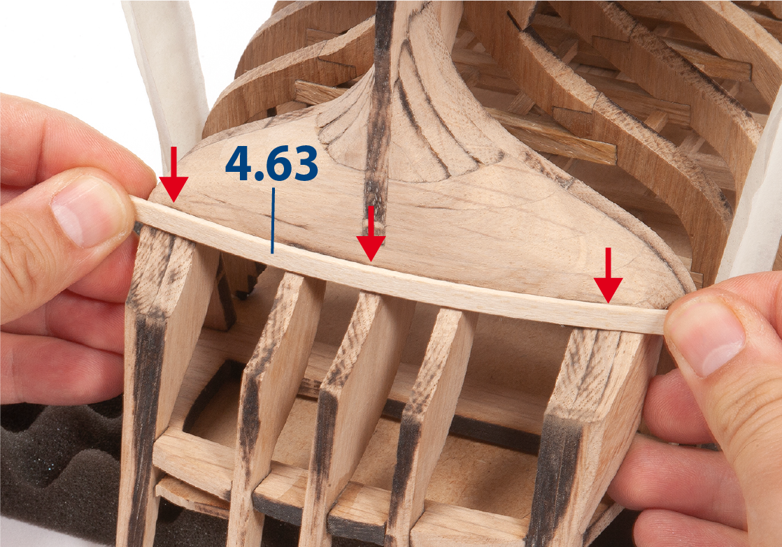
ステップ 10
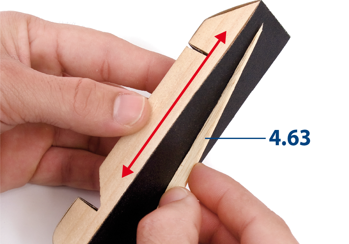
Glue three more pieces 4.63.
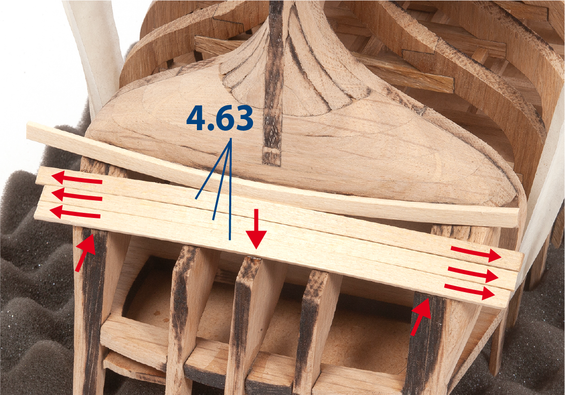
ステップ 11
Glue two more pieces 4.63 together.
ステップ 12
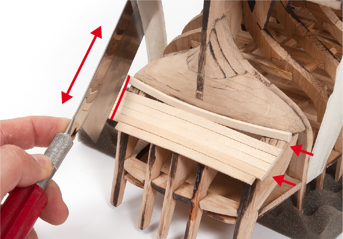
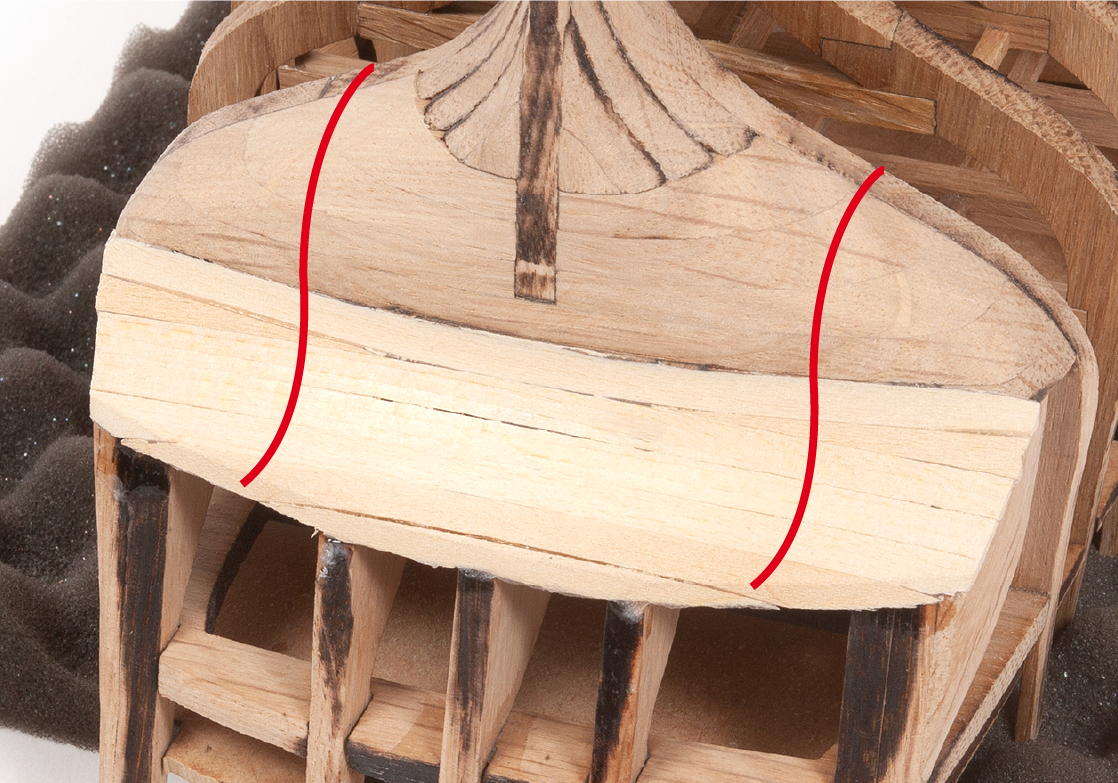
Cut off the excess battens flush with the sides of the hull.
ステップ 13
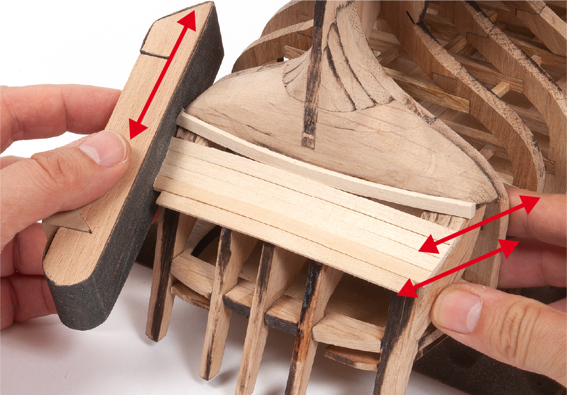
Sand the ends of the battens to match the hull.
ステップ 14
Sand the battens following the inclination of the aft parts.
ステップ 1
Make two wedges with a 2x5mm strip.
ステップ 2
Use a sanding block to adjust each wedge.
ステップ 3
Insert and glue the wedges.
ステップ 4
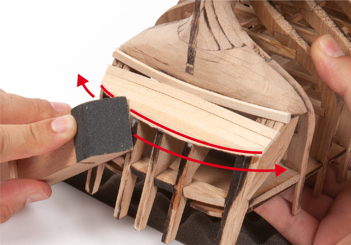
Sand the stern battens to achieve a smooth surface as shown in the picture.
ステップ 5
Place part 4.64 on top of the upper beams and secure it there. Make sure part 4.64 is level. Use a marker pen to mark a line above the part on the outside of the frames.
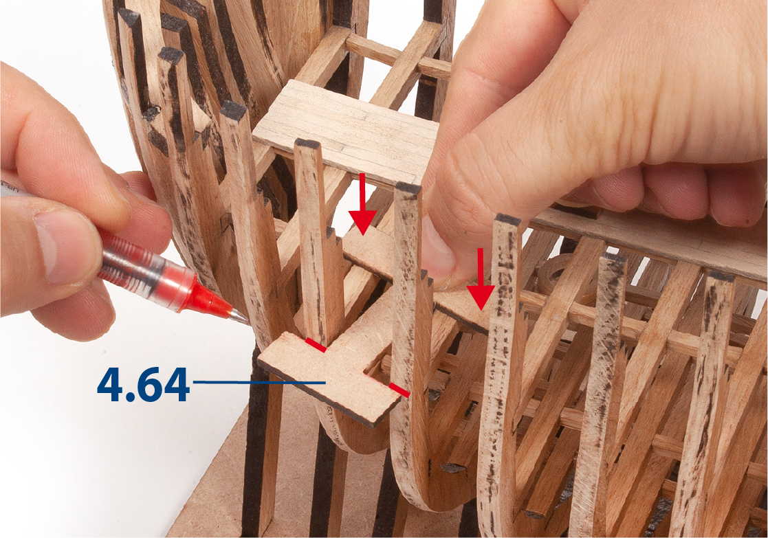
ステップ 6
This should be done on both sides of the hull and along its entire length.
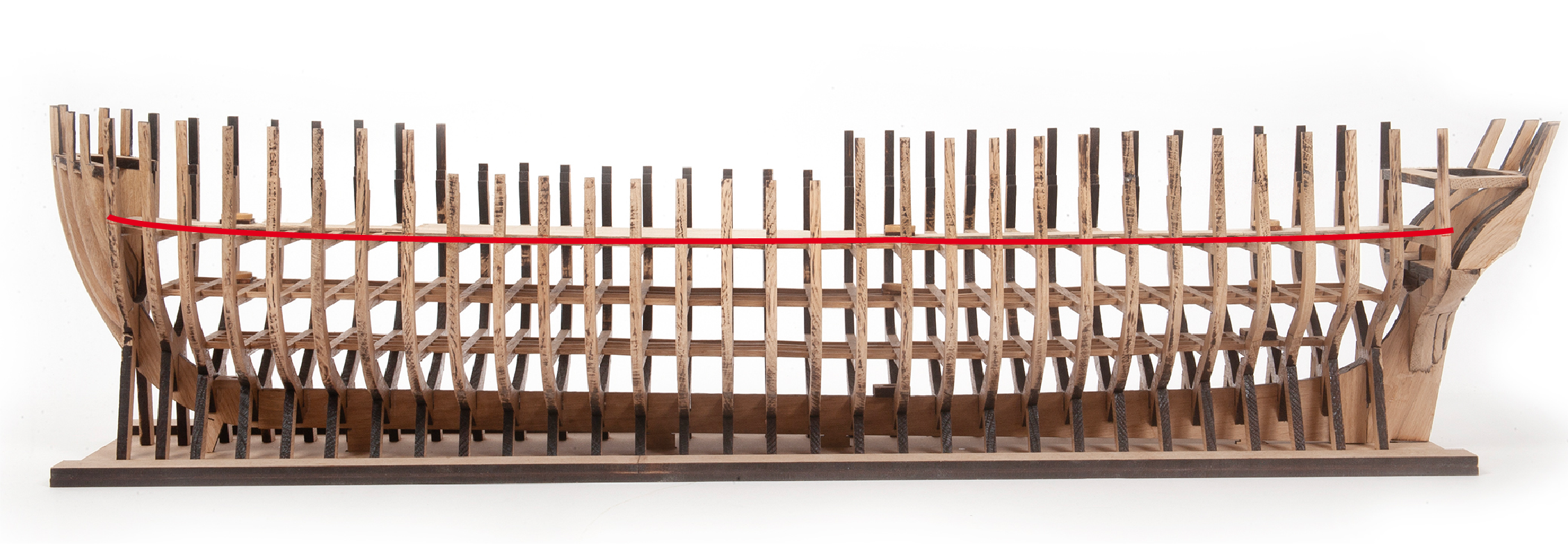
ステップ 7
Note the line from bow to stern in the picture.
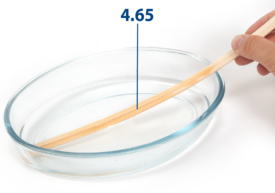
ステップ 8
Soak a pair of sanded 4.65 battens (2 x 5 x 600 mm) in water for about 15 minutes. This will make them more flexible.
ステップ 9
Dry the battens with blotting paper, and use an iron to bend the battens slightly. You should lift the batten as you apply heat to it.
ステップ 10
Present the batten in the mid-hull area just below the line you drew with part 4.64. It must make contact with all the frames on its course.
Note: It may be helpful at this point to check you have space for 7 lines of planking - use the images in Stage 19 for reference.
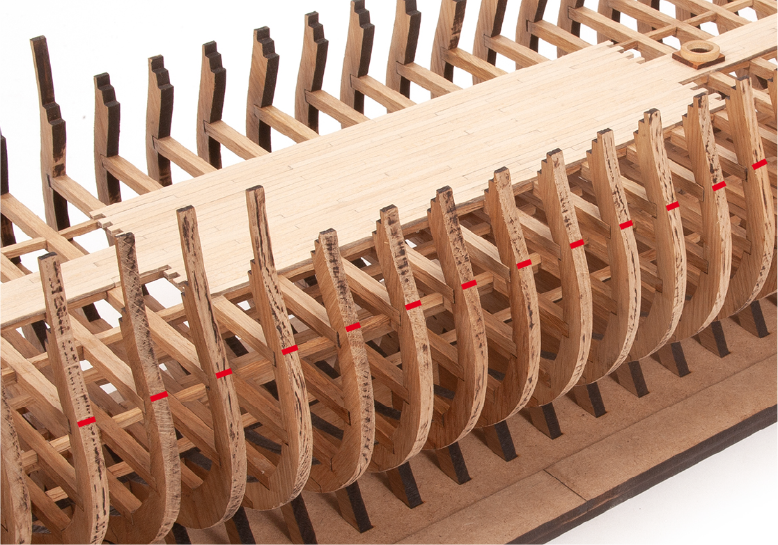
ステップ 11
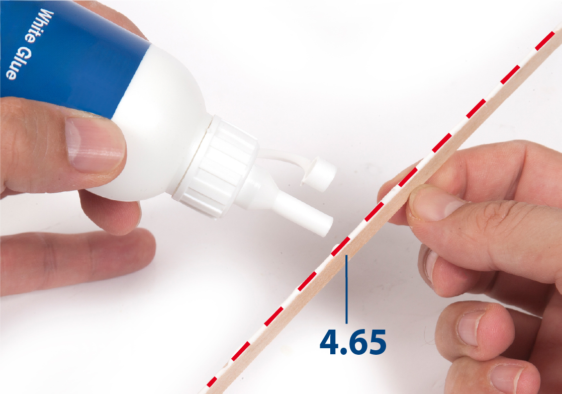
Apply white glue to the areas of the frames where the part 4.65 will make contact.
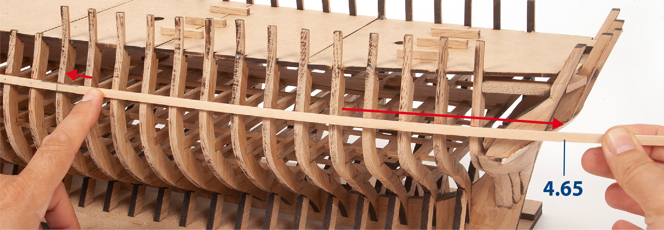
ステップ 12
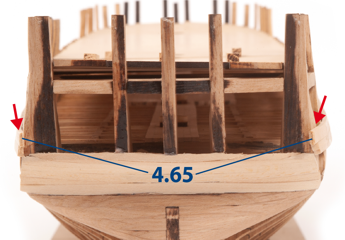
Position the 4.65 batten so that it reaches from the centre of frame 18 to beyond the fore false keel. Keep the part immobilized with clamps or similar until the glue dries.
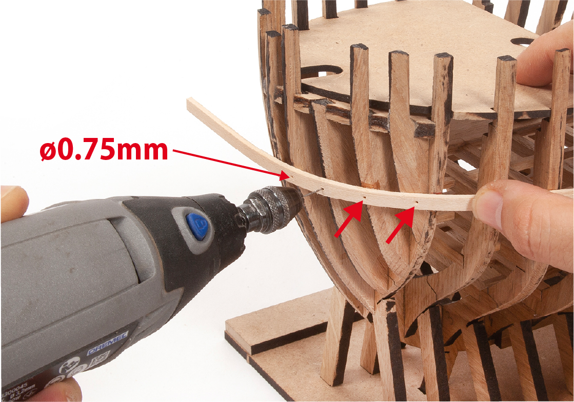
ステップ 1
After the glue has dried, use an electric drill to drill ø0.75 mm holes at the intersection between the frames and the batten.
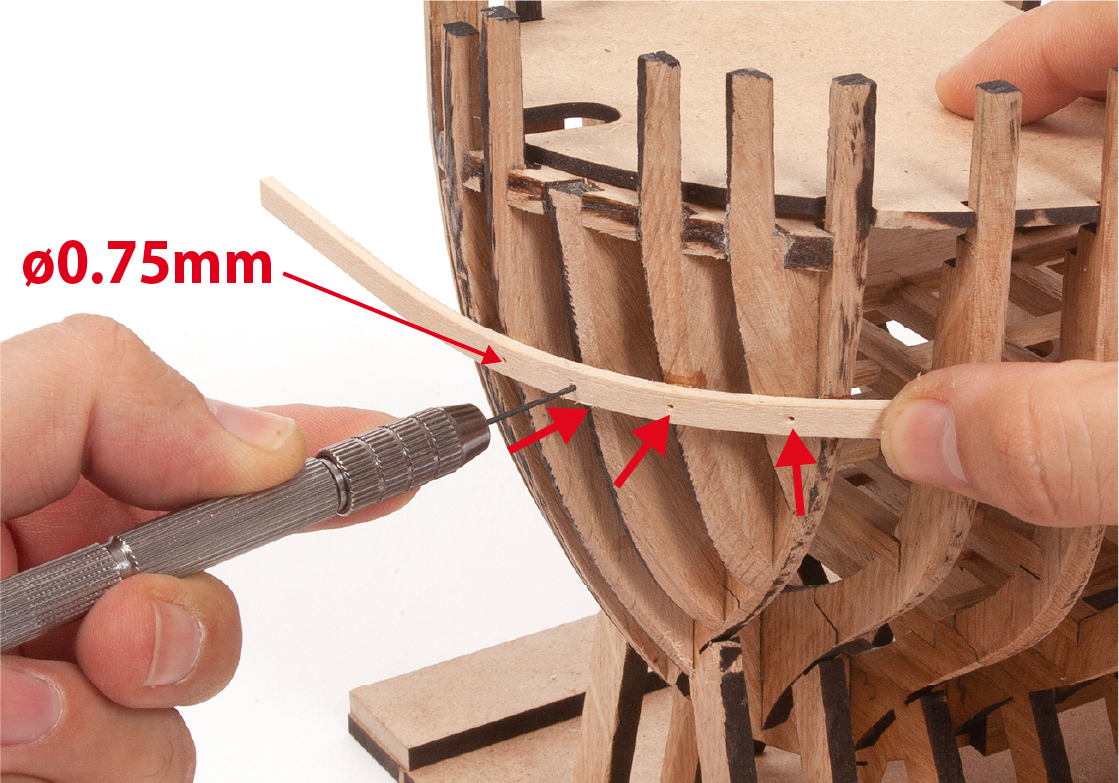
ステップ 2
You can perform the same operation with a manual drill.
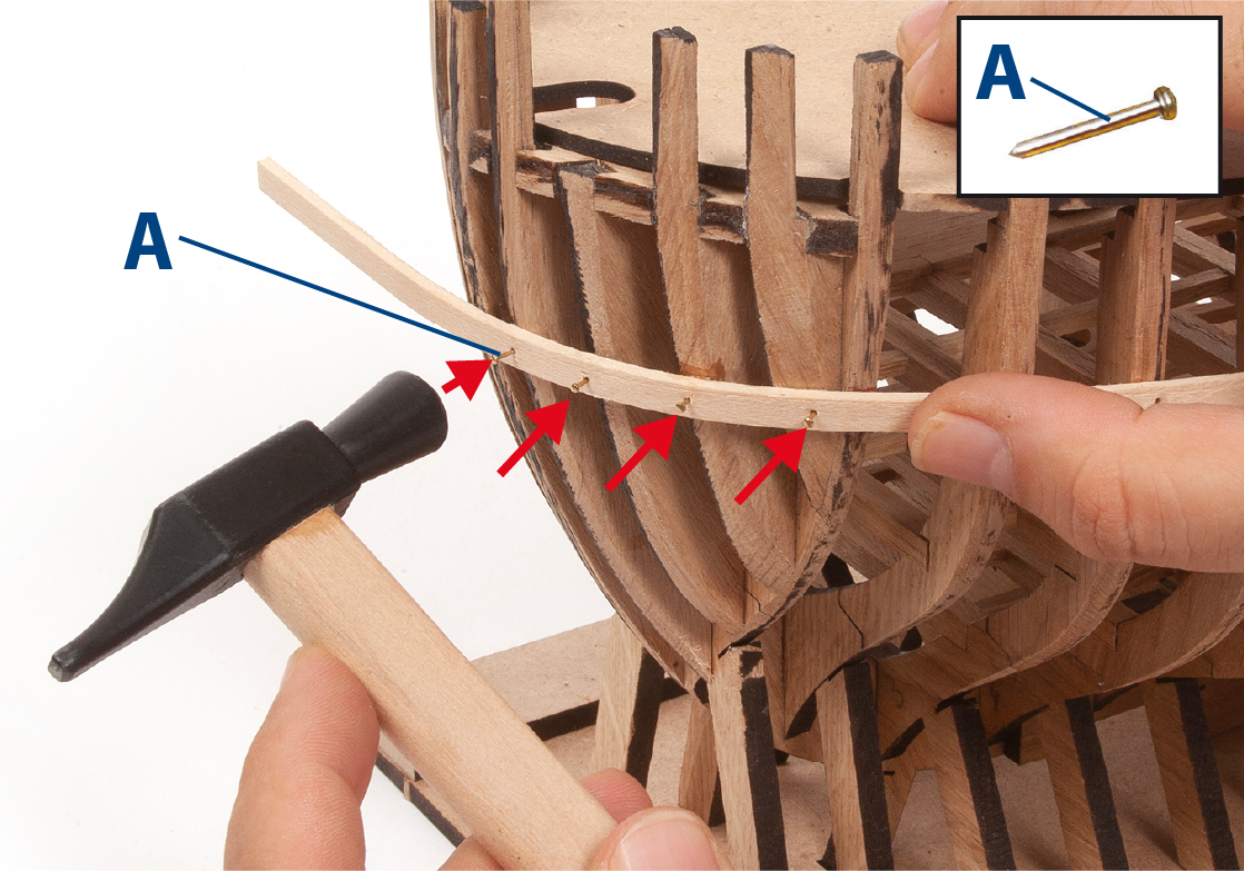
ステップ 3
Apply glue and insert an A-nail into each hole. The tips should only be inserted as far as they will hold the batten in place, not all the way in.
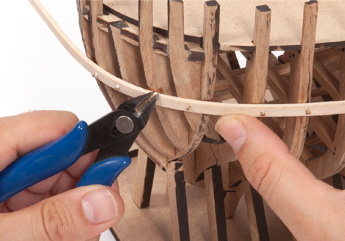
ステップ 4
Then, when the glue has dried, cut the ends flush with the batten.
ステップ 5
Use a flat file to flush the ends with the batten.
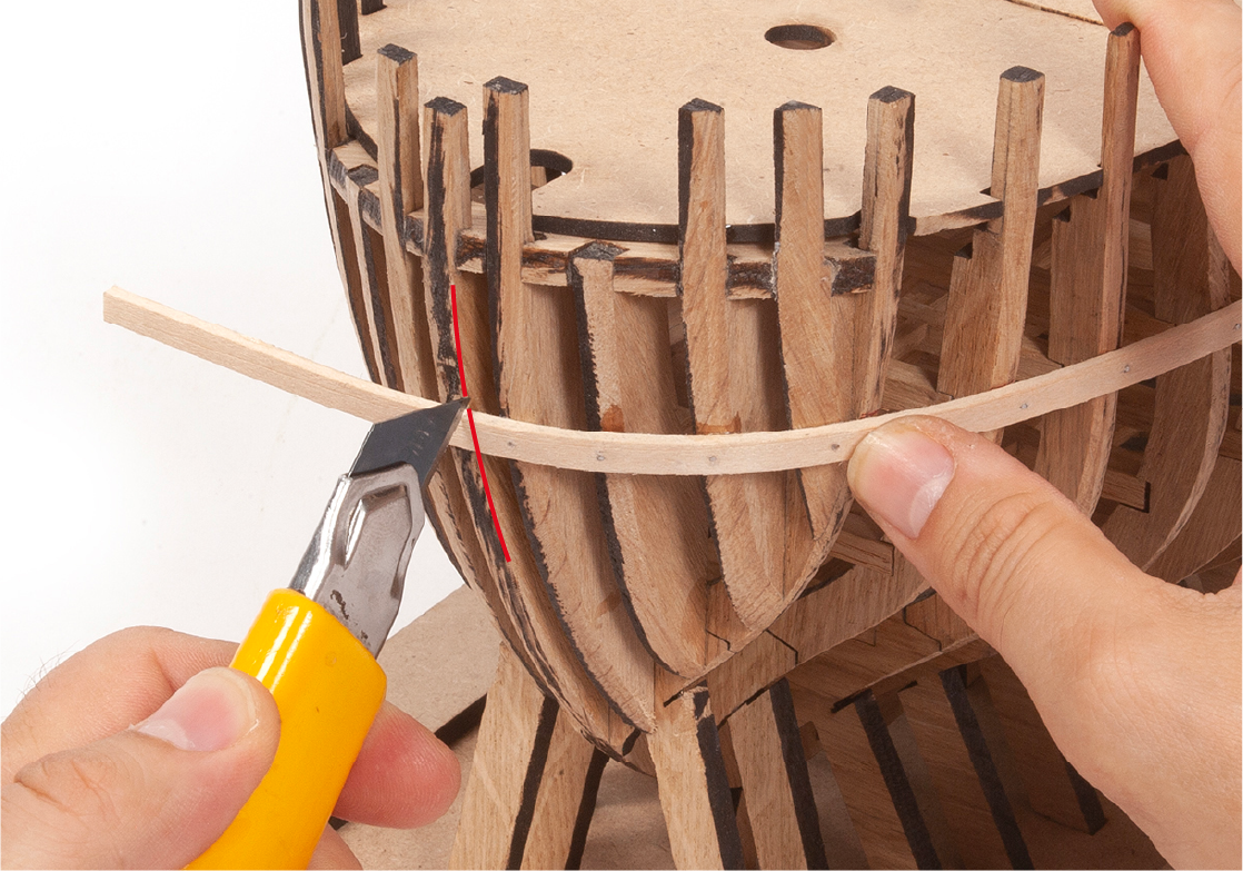
ステップ 6
Cut the batten close to the centre piece of the hull.
ステップ 7
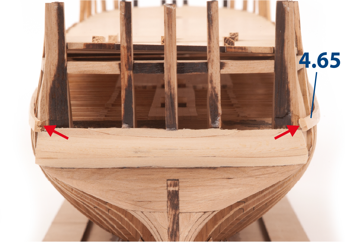
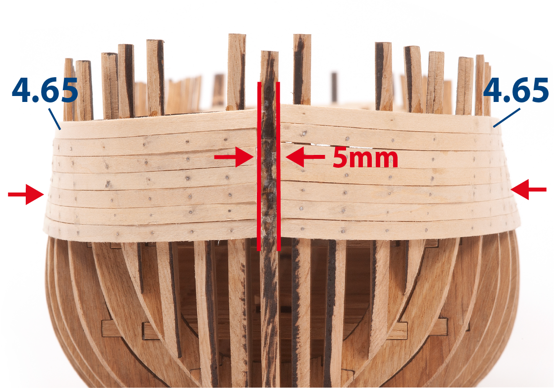
Glue another 4.65 batten in line with the previous batten, running from the centre of frame 18 to the rear of the hull.
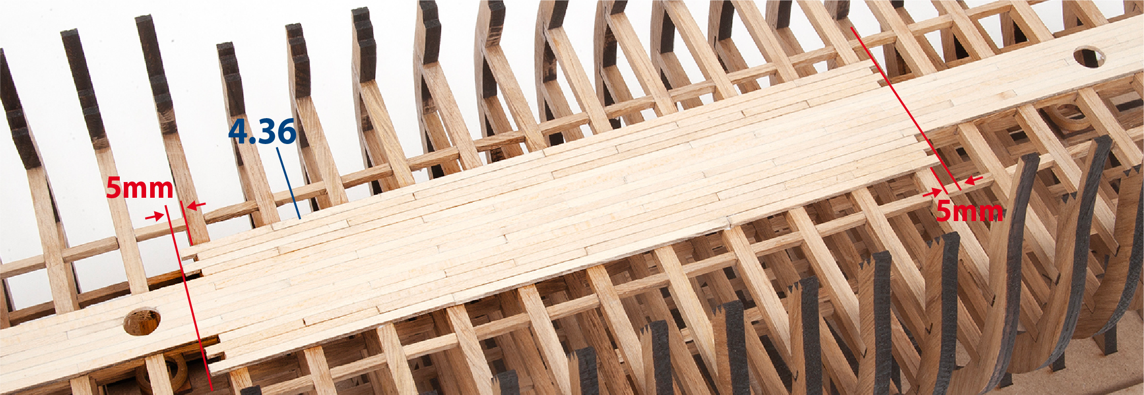
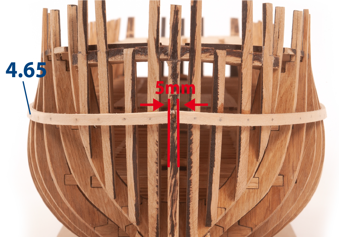
ステップ 8
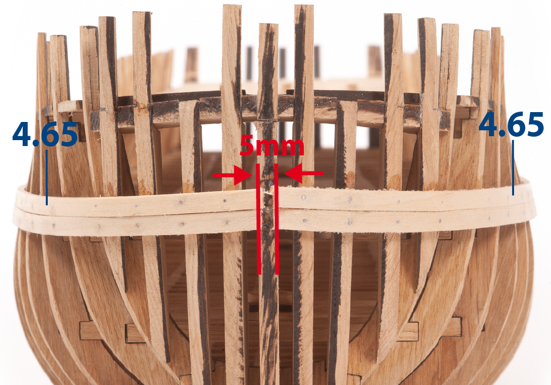
Do the same on the other side of the hull to achieve a symmetrical finish. Note that a 5 mm-wide gap must be maintained in the centre.
ステップ 9
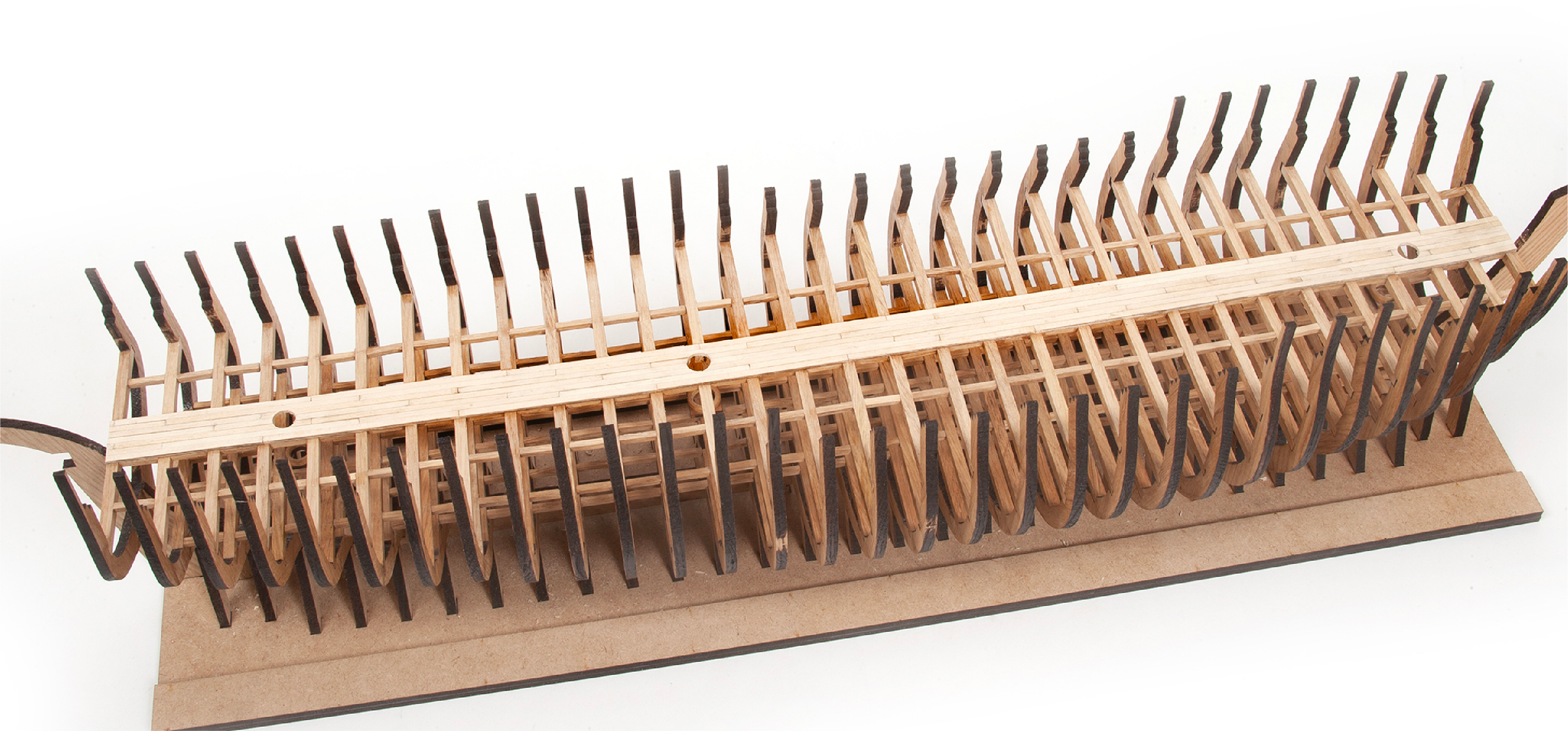
Note how the battens should be fitted aft of the hull.
ステップ 10
Apply white glue to the full length of another 4.65 batten.
ステップ 11
Glue the batten to start another line of planking above the previous one. The same processes should be repeated on both sides of the hull to achieve a symmetrical finish.
ステップ 12
Complete the planking line with another piece of batten.
ステップ 13
You must vary the joints between the slats so that they do not always coincide in the same frame.

ステップ 14
Cut off any excess battens flush with the stern of the hull.
ステップ 1
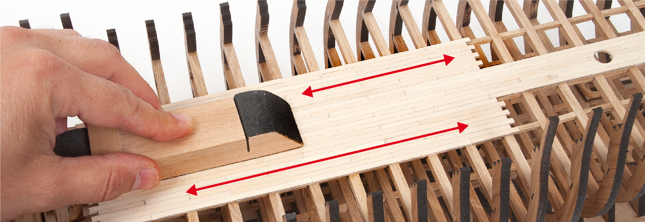
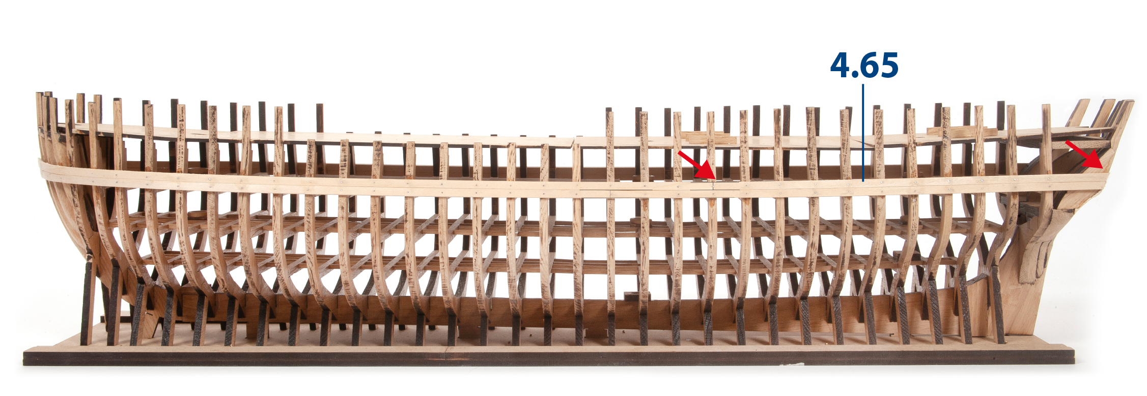
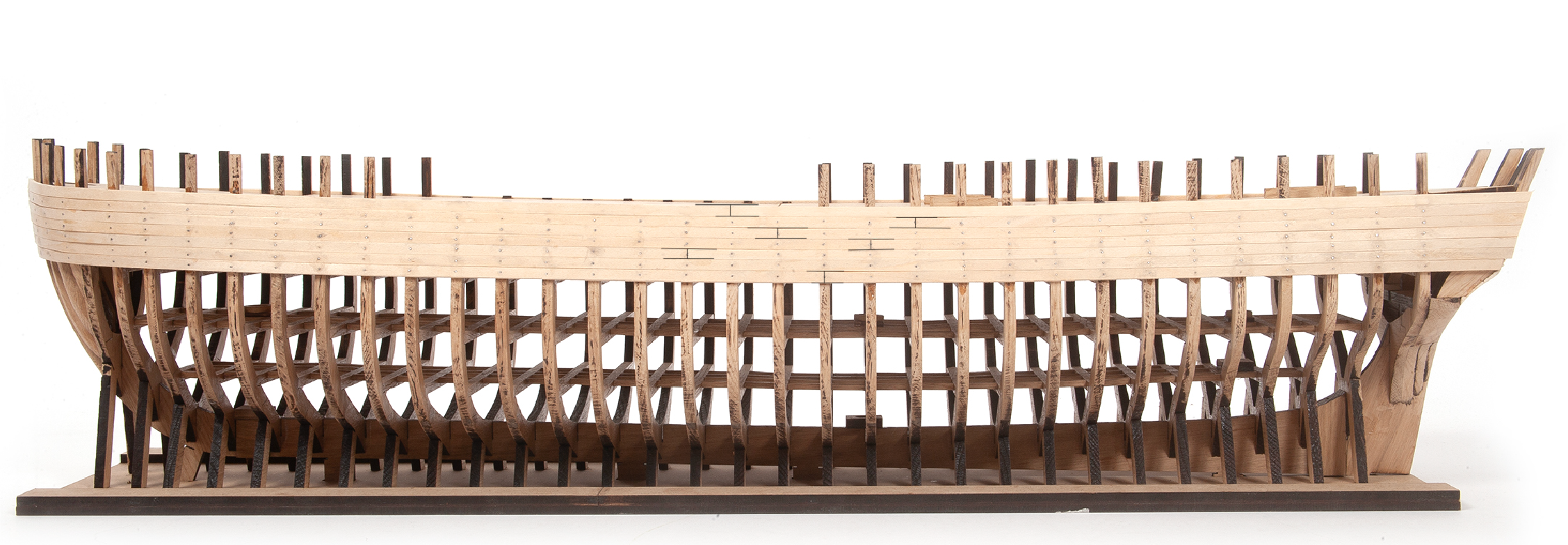
Fit five more lines of planking with the 4.65 pieces.
Image b. serves as a guide to demonstrate how the planking extends beyond the hull.
Cut the battens leaving 5 mm at the bow.
ステップ 2
You must vary the joining of the battens so that they do not always coincide at the same frame.
ステップ 3
Cut off any excess battens flush with the stern of the hull.
ステップ 4
Continue to line the hull in the bow area, but without nailing points. This area of the hull is more fragile and should be held in place with clamps.
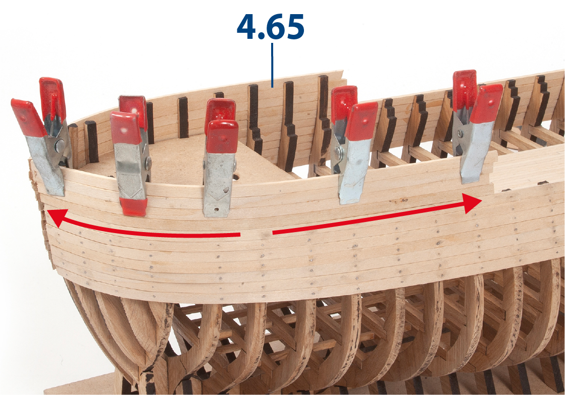
ステップ 5
Note in the picture the inside of the bow planking.
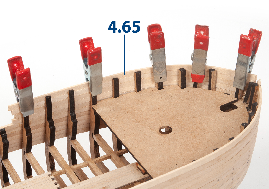
ステップ 6
Complete the bow and stern planking as shown in the picture, without nailing points.
ステップ 7
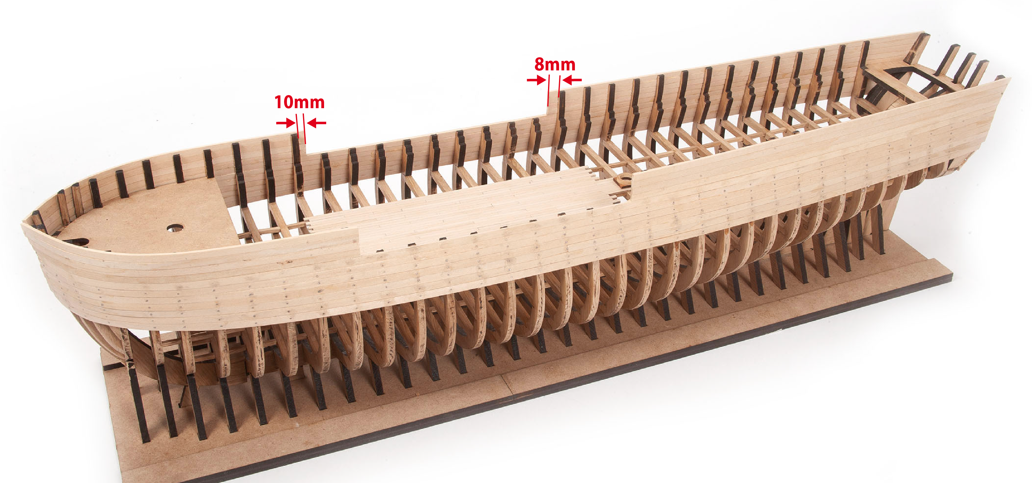
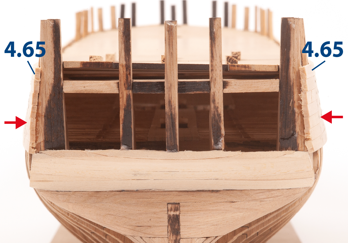
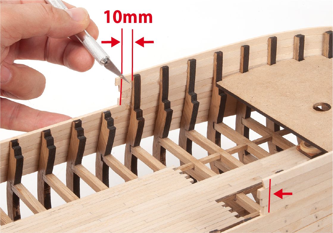
Cut the ends of the battens leaving 10 mm space in the bow area.
ステップ 8
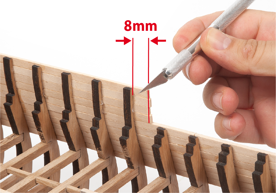
Cut the ends of the battens leaving 8mm of space in the aft area.
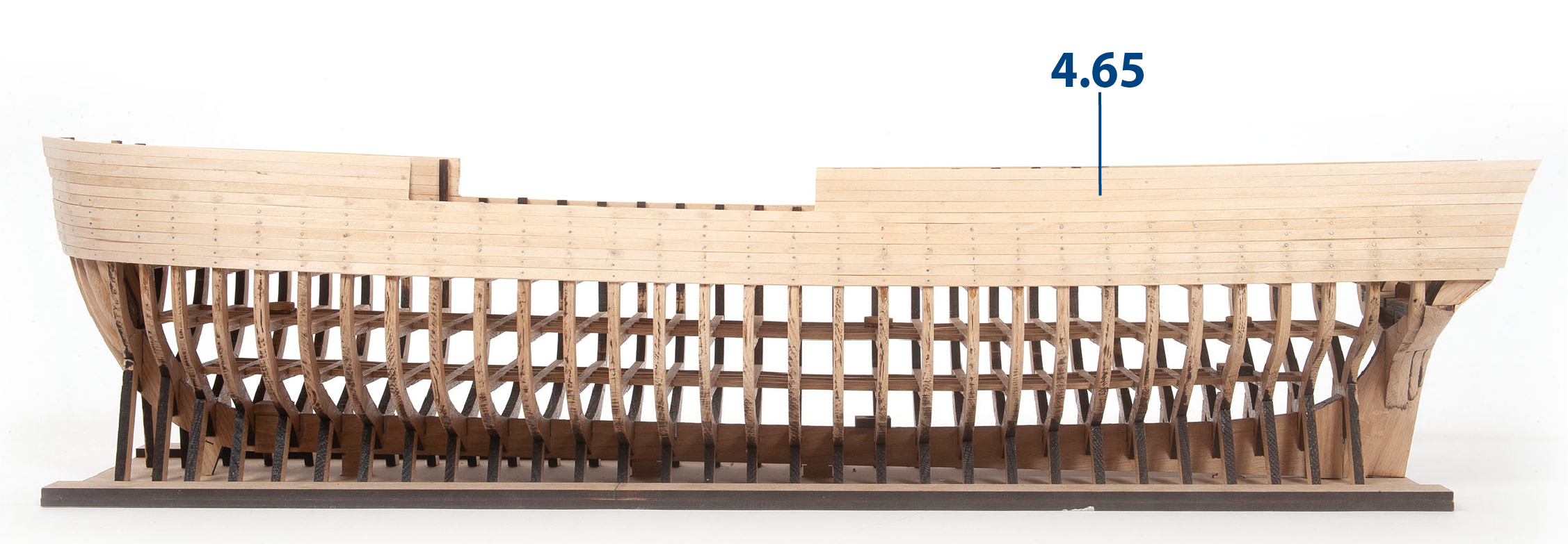
ステップ 9
In the picture you can see how the complete hull planking should look. Pay attention to the measurements shown which indicate precisely the width of the battens. The image may look slightly different, but the measurements are correct.