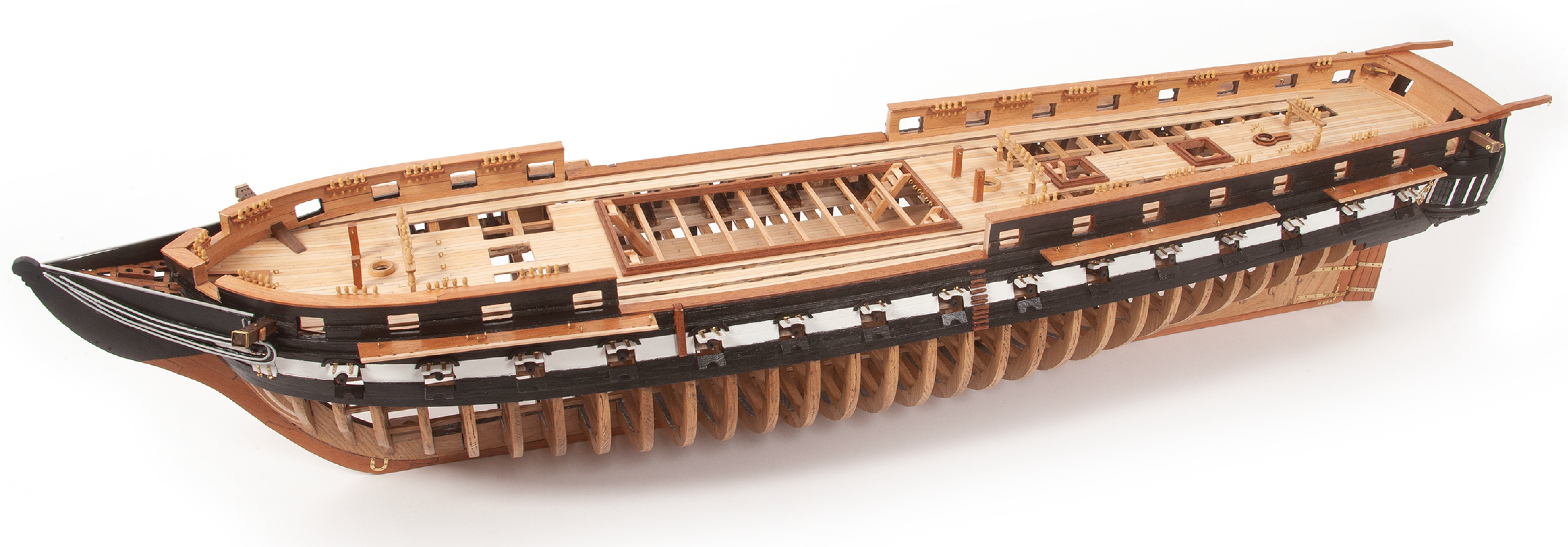
Pack 9
BUILD INSTRUCTIONS
Instructions for building your USS Constitution model ship
Your model of the USS Constitution is divided into 12 packs.
You will need to follow the step-by-step assembly photos, the plans and the explanatory texts below.
Please save the leftover materials from each pack for use when instructed to do so at a later stage of the assembly instructions.
The IP sheets displayed below are drawings of laser-cut parts and photo-etched brass parts and will serve as a guide for identification of some parts.
Use the PARTS REFERENCE table to help locate the parts.
The PL-00 templates (printed at 1/1 scale) included in each pack will serve as a guide for building the model.
Please check the list below to ensure you have all the tools required for building your wooden ship.
When removing a part, cut the ribs that join the part to the wooden plate with a cutter.
Remove the parts carefully so as not to break them.
Keep and store the parts in their frames. Only remove the parts you are working on in each step.
Extra support can be found on our forum or from the Expert Directory page of our website.
PARTS LIST
| Material | Quantity | |
| Wooden Strips | ||
| 1 x 4 x 100 mm | Lime wood | 14 |
| Other Parts | ||
| Wire ø1 x 100 mm | Brass | 35 |
| Wire ø1.5 x 100 mm | Brass | 5 |
| Wire ø0.5 x 100 mm | Brass | 60 |
| Ring ø3 mm | Brass | 125 |
| Set of ladder stringers | 7 | |
| Large cleat | Brass | 2 |
| Small cleat | Brass | 12 |
| Pulley 4 mm | 150 | |
| Block 4 mm | 75 | |
| Boom band | Brass | 1 |
| Mast band | Brass | 2 |
| Parrel cleat | Brass | 6 |
| Window glass | Acetate | 2 |
Tools you will need: cutting mat, pencil, cutting knife, fine-grit sandpaper or sponge sandpaper, file, white wood glue, super glue (cyanoacrylate glue), masking tape, set square, hacksaw, sanding block, 30 cm steel ruler, clamps, drill, moulding scriber tool
PARTS REFERENCE
PART NO. | IP-SHEET LOCATION | PART NO. | IP-SHEET LOCATION | PART NO. | IP-SHEET LOCATION |
| 9.5 | 2001-22 | 9.24 | 2001-23 | 9.30 | 2001-23 |
| 9.6 | 2001-22 | 9.25 | 2001-23 | 9.31 | 2001-23 |
| 9.9 | 2001-22 | 9.26 | 2001-23 | 9.39 | 2001-29 |
| 9.10 | 2001-22 | 9.27 | 2001-23 | 9.46 | 2001-32 |
| 9.11 | 2001-22 | 9.28 | 2001-23 | 9.47 | 2001-32 |
| 9.22 | 2001-23 | 9.29 | 2001-23 | 9.50 | 2001-33 |
| 9.23 | 2001-23 | 9.30 | 2001-23 | 9.51 | 2001-32 |
ステップ 1
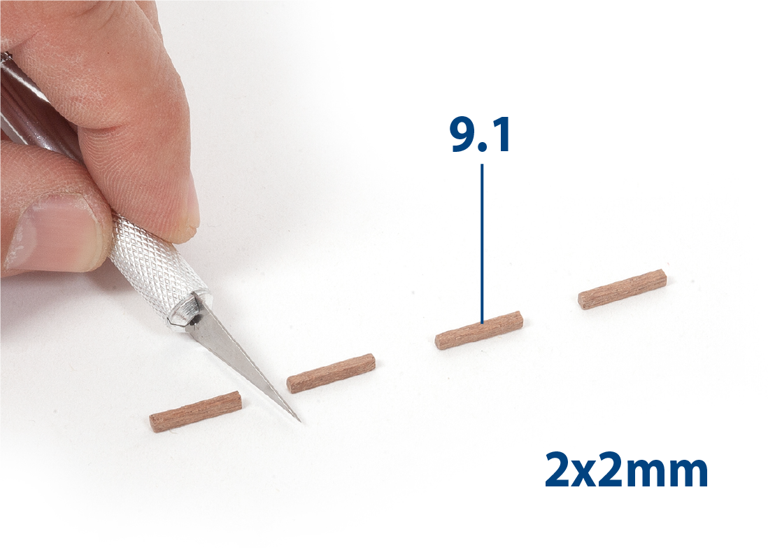
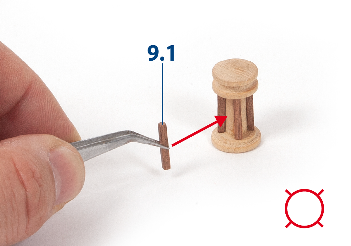
Cut eight parts 9.1 (2 x 2 x 136 mm mahogany) to length and sand them.
ステップ 2
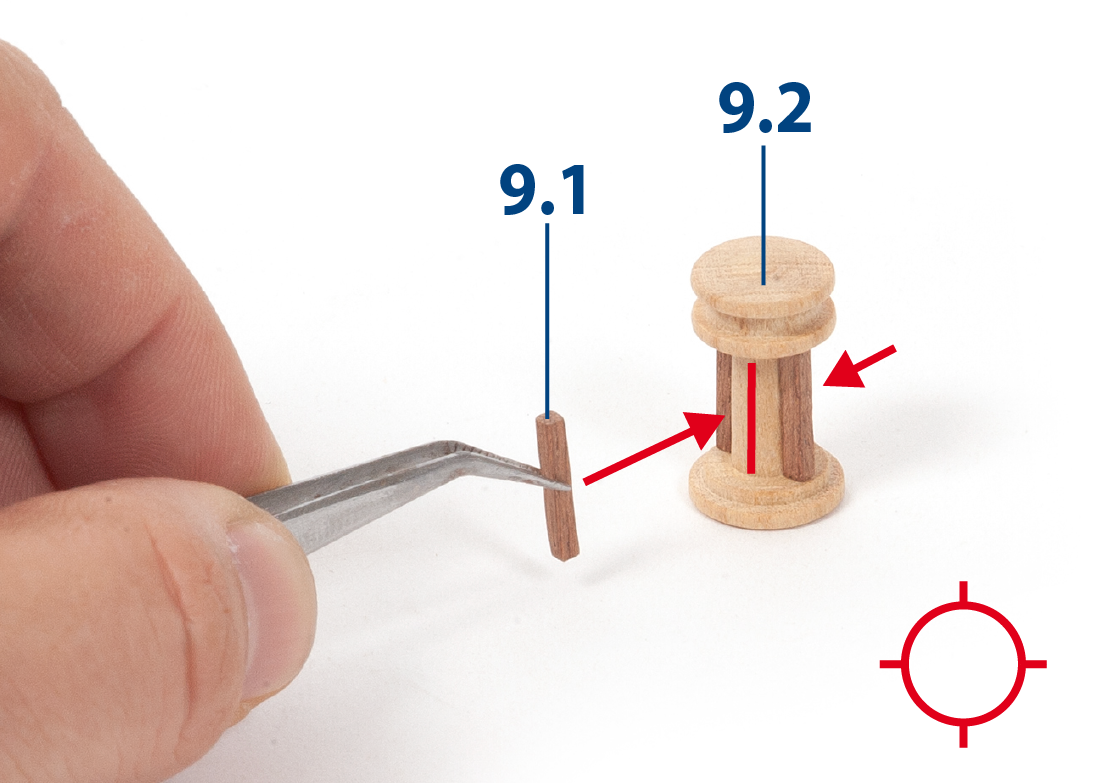
Fit and glue parts 9.1 onto part 9.2 (capstan, pack 08) as shown.
ステップ 3
Continue to fit and glue parts 9.1 to the assembly as shown.
ステップ 4
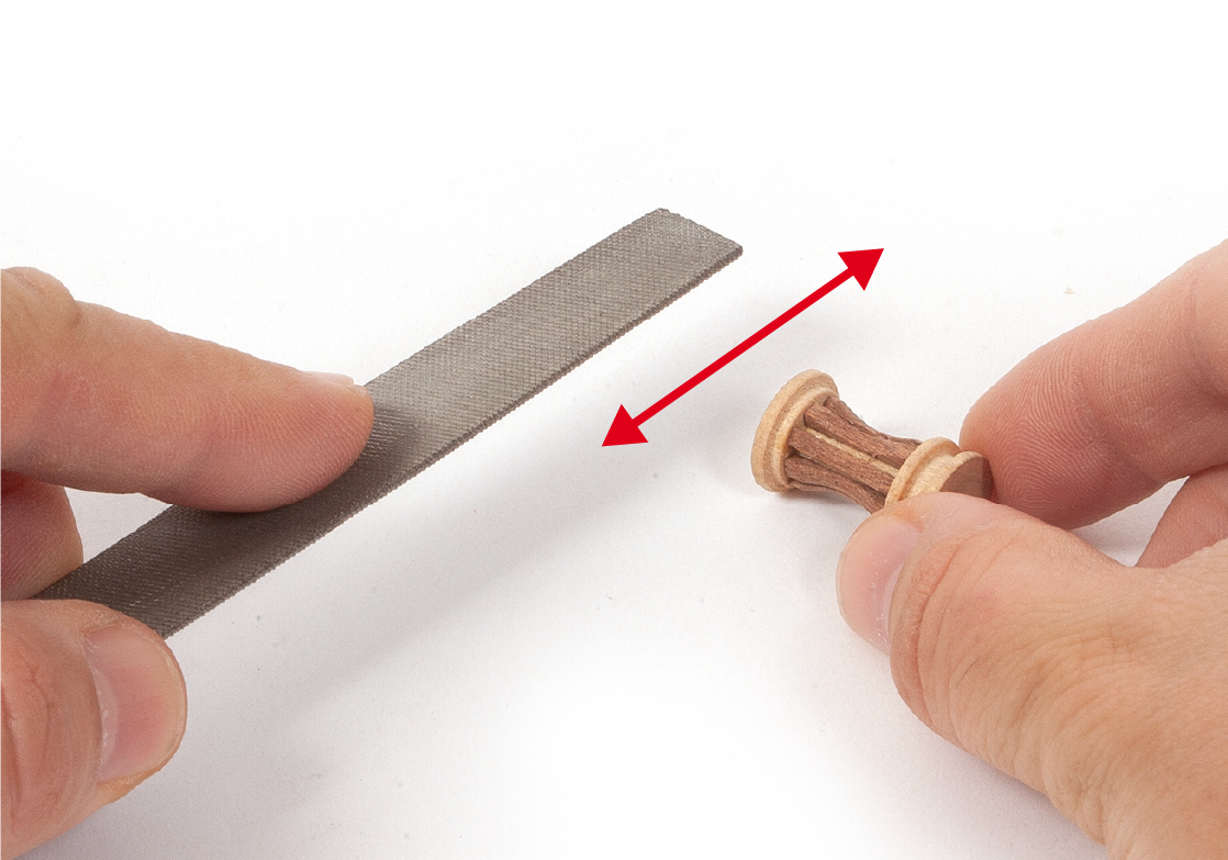
Use a rounded file to shape parts 9.1.
ステップ 5
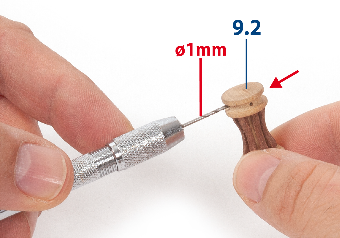
Drill eight holes (ø1 mm) into part 9.2 as shown in the image (see step 8).
ステップ 6
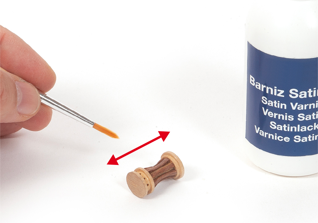
Apply varnish to the assembly.
ステップ 7
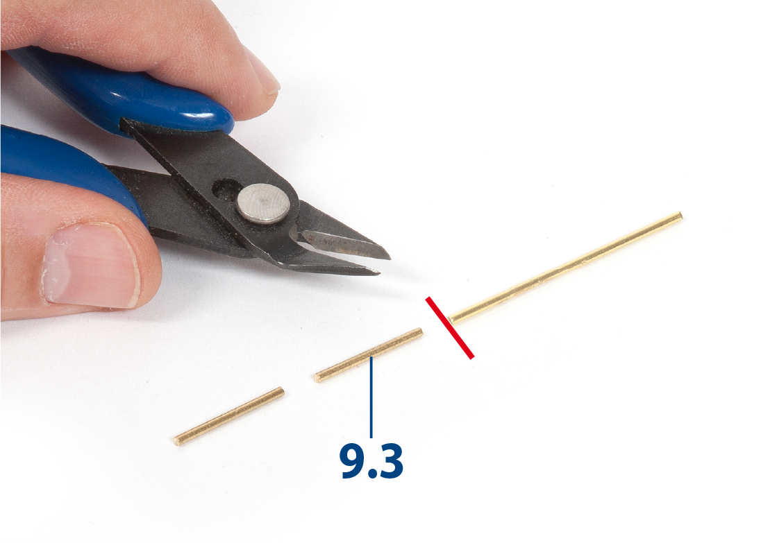
Cut to length eight parts 9.3 (ø1 x 10 mm).
ステップ 8
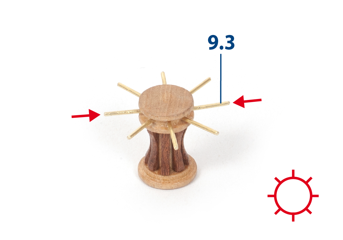
Insert and glue parts 9.3 as shown in the image.
ステップ 9
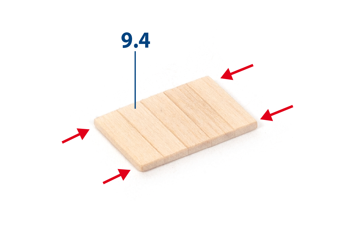
Cut to length and glue parts 9.4 (2 x 5 x 17 mm lime wood) together as shown.
ステップ 10
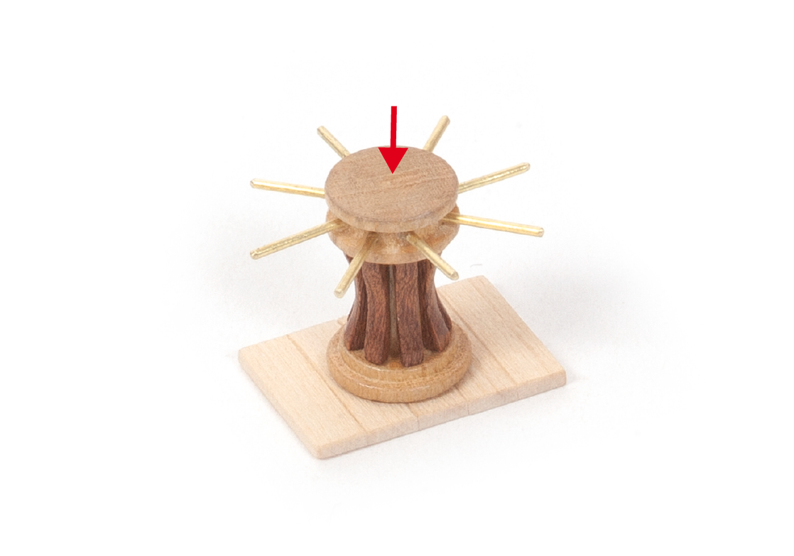
Glue part 9.2 centred on parts 9.4. Varnish parts 9.4, then set aside.
ステップ 11
Glue parts 9.5 together.
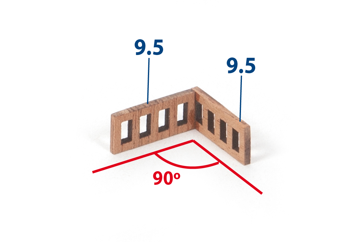
ステップ 12
Glue two more parts 9.5 to the assembly.
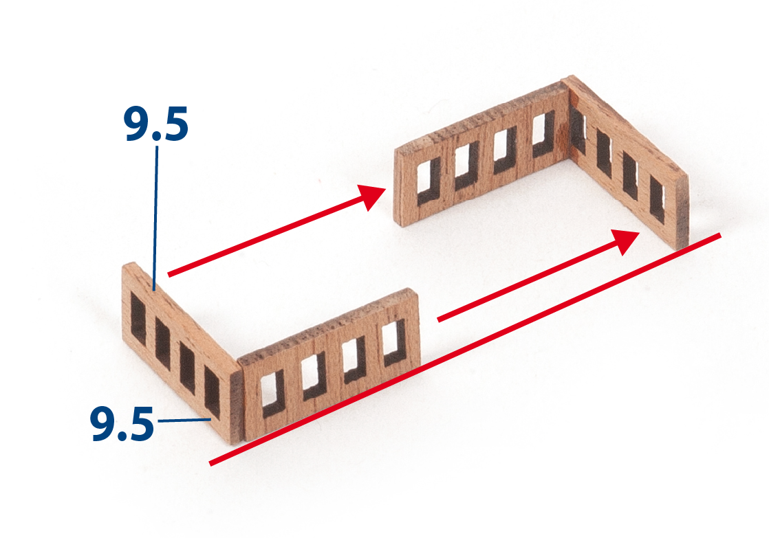
ステップ 13
Glue the assembly centred on part 9.6.
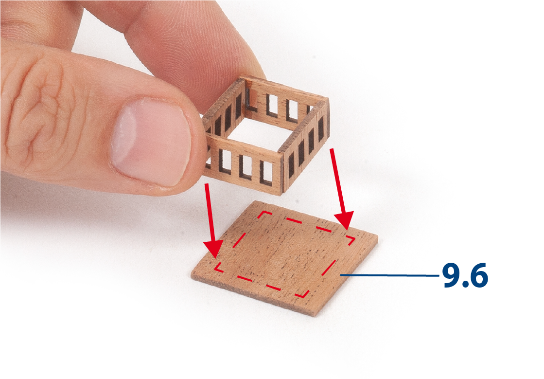
ステップ 14
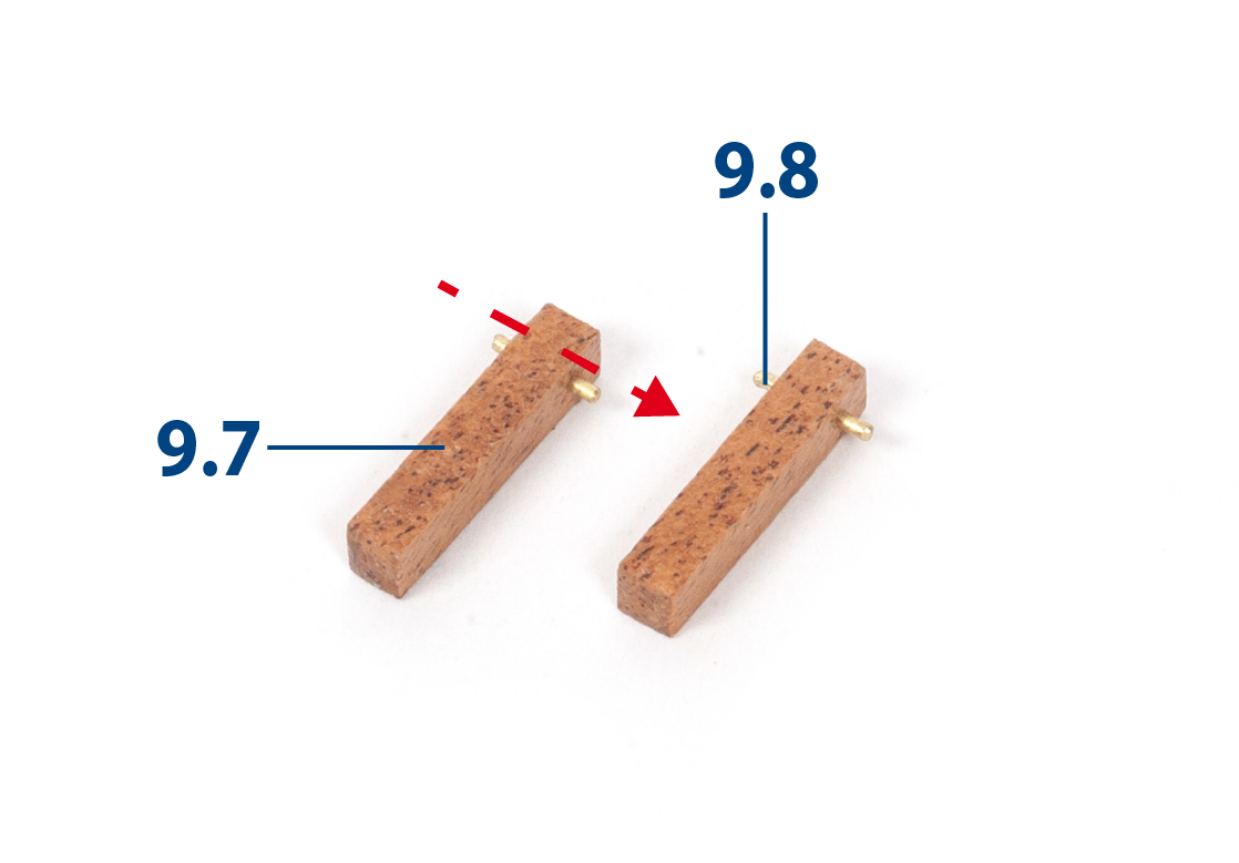
Cut four parts 9.7 to size (4 x 4 x 20 mm mahogany) and drill a hole in each one as shown in the image.
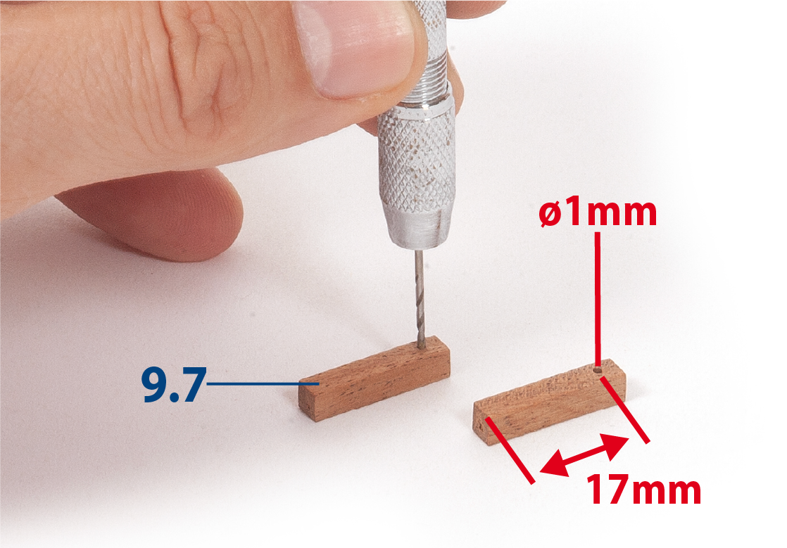
ステップ 15
Cut parts 9.8 (ø1 x 8 mm) to length and insert them.
ステップ 16
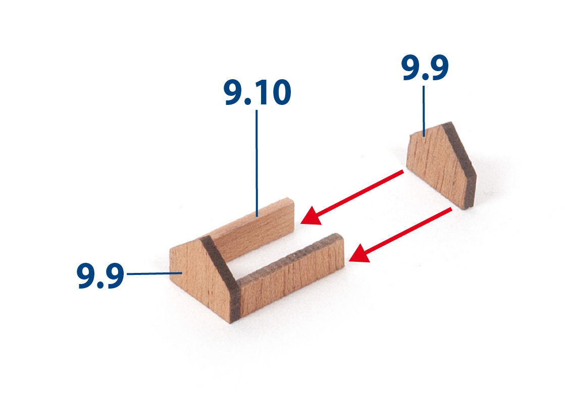
Glue parts 9.9 and 9.10 together.
ステップ 17
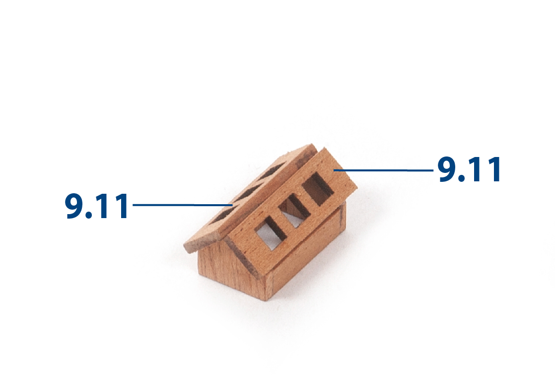
Glue parts 9.11 as shown to complete the assembly.
ステップ 18
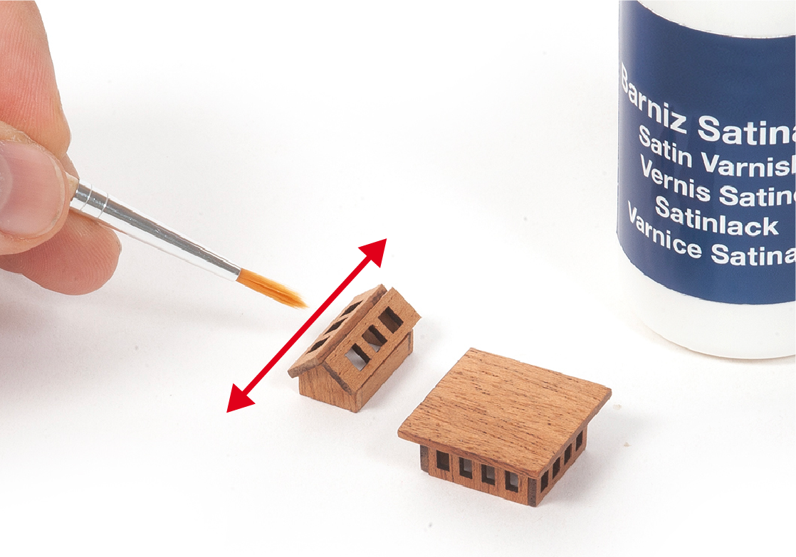
Apply varnish to the two assemblies shown in the image.
ステップ 1
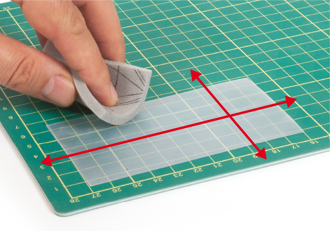
Take one of the sheets of acetate then scratch one of its sides using sandpaper or similar.
ステップ 2
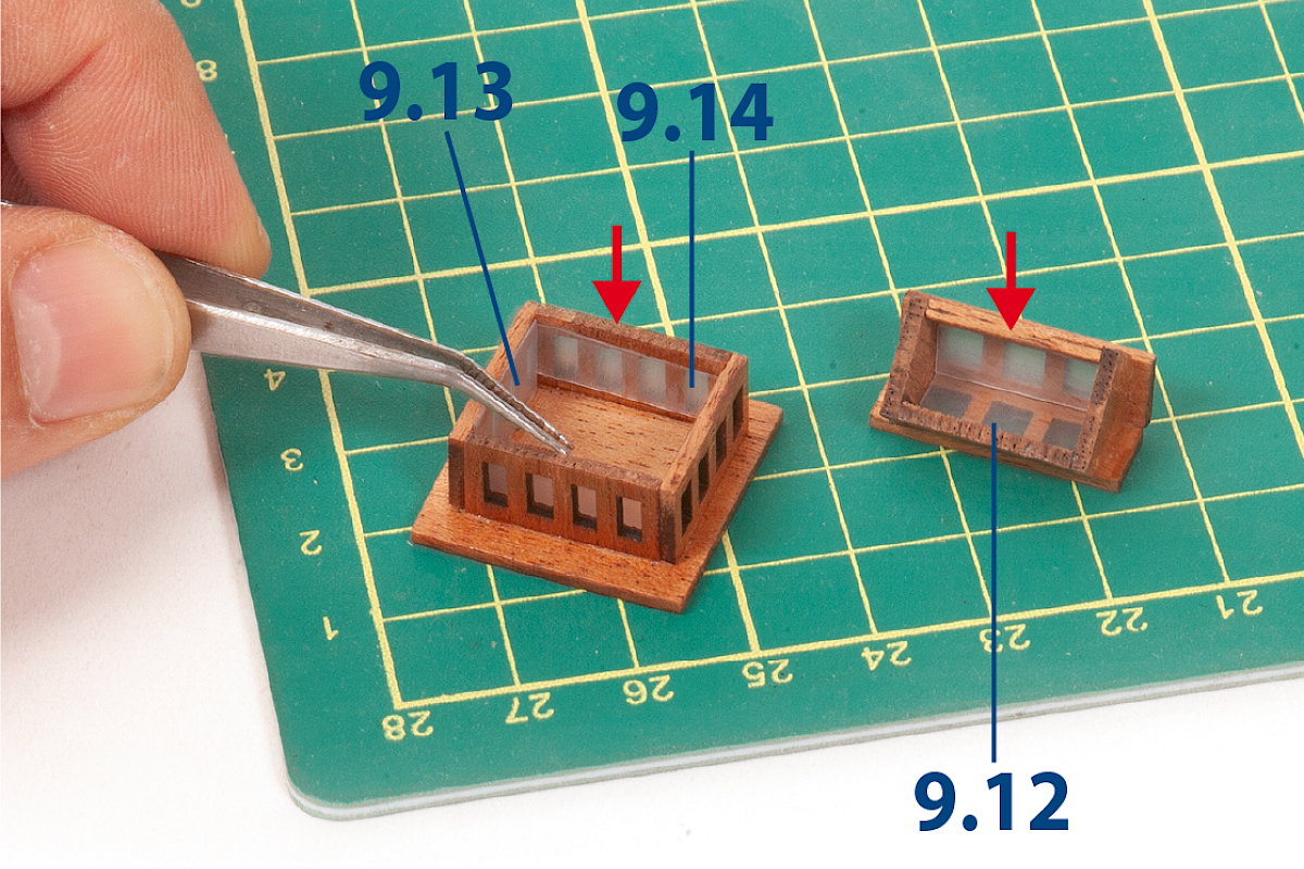
Cut out parts 9.12, 9.13 and 9.14 (two of each part). These parts represent the window glass. Glue the parts inside the two assemblies as shown.
| 9.12: 5 x 15 mm |
| 9.13: 8 x 14 mm |
| 9.14: 8 x 17 mm |
ステップ 3
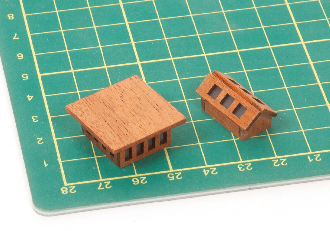
This image shows the assemblies with the acetate glued in place.
ステップ 4
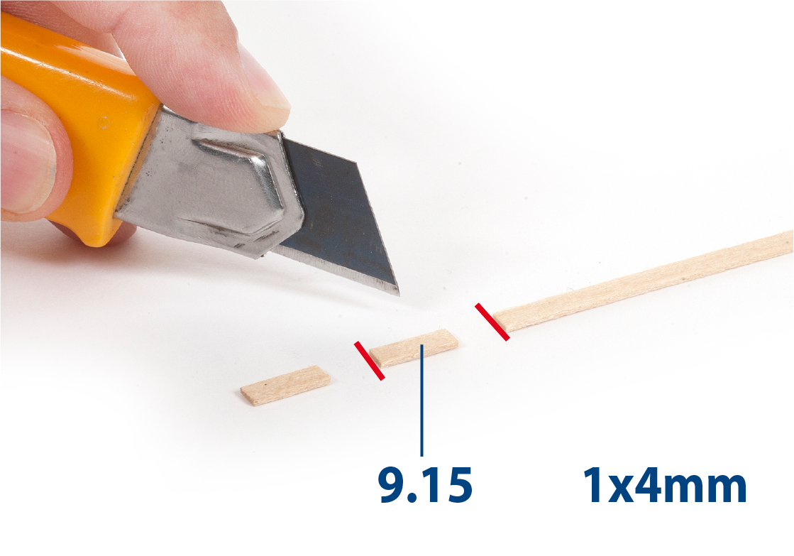
Cut to length eighteen parts 9.15 (1 x 4 x 7 mm lime wood).
ステップ 5
Fit and glue parts 9.15 into part 9.16 (ladder stringer).
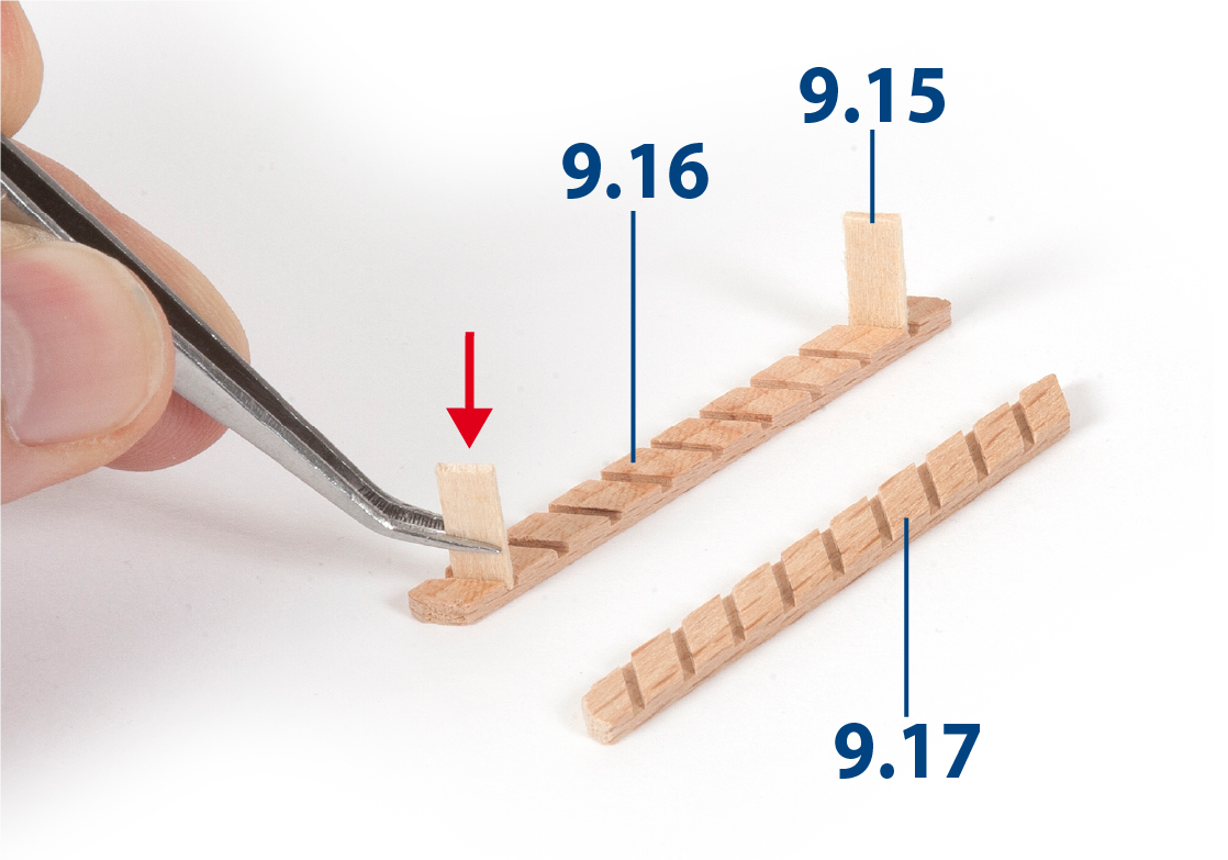
ステップ 6
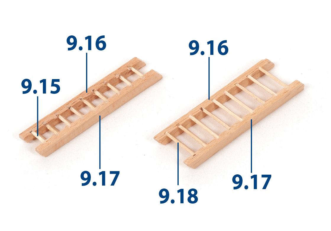
Glue part 9.17 to complete the ladder. Repeat this process to build a second ladder.
Build five wide ladders using parts 9.16, 9.17 and 9.18 (1 x 4 x 12 mm) in the same way. Once complete, varnish all the ladders.
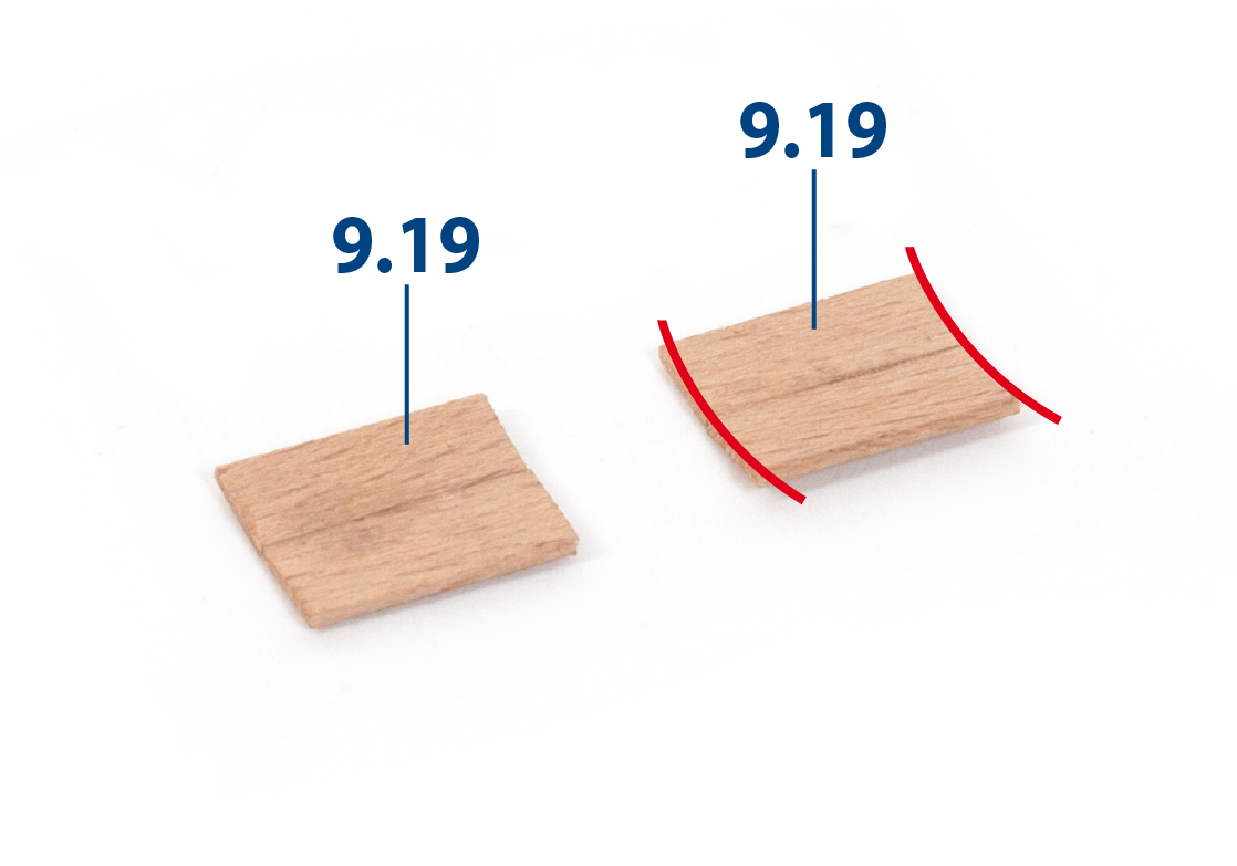
ステップ 7
Cut to length four parts 9.19 (1 x 5 x 12 mm), then glue the parts together in the form of a curve as shown.
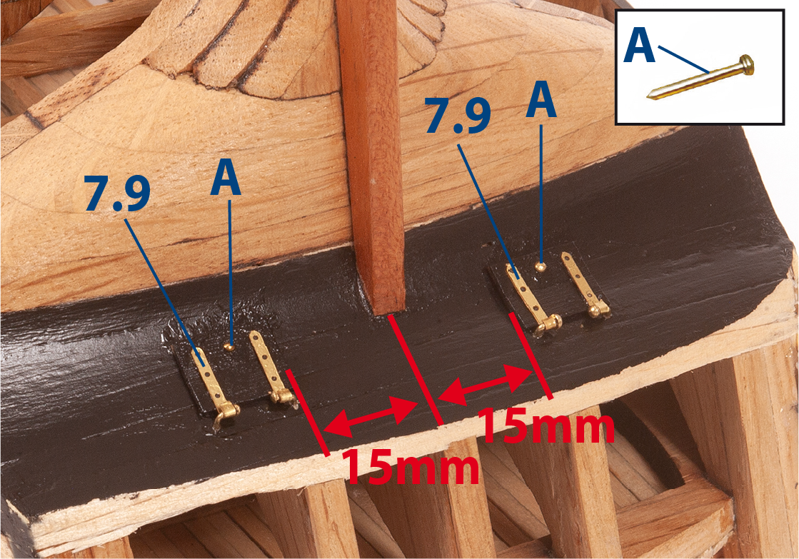
ステップ 8
Paint the curved parts black, then glue hinges 7.9 to the parts as shown, and fit the hinges in place using nails (A).
ステップ 9
Drill and cut the openings shown in the image. You can position the transom in place to show where to drill (see Stage 51 Step 3 below).
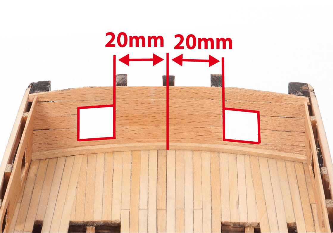
ステップ 10
Paint the outside of the hull black as shown.
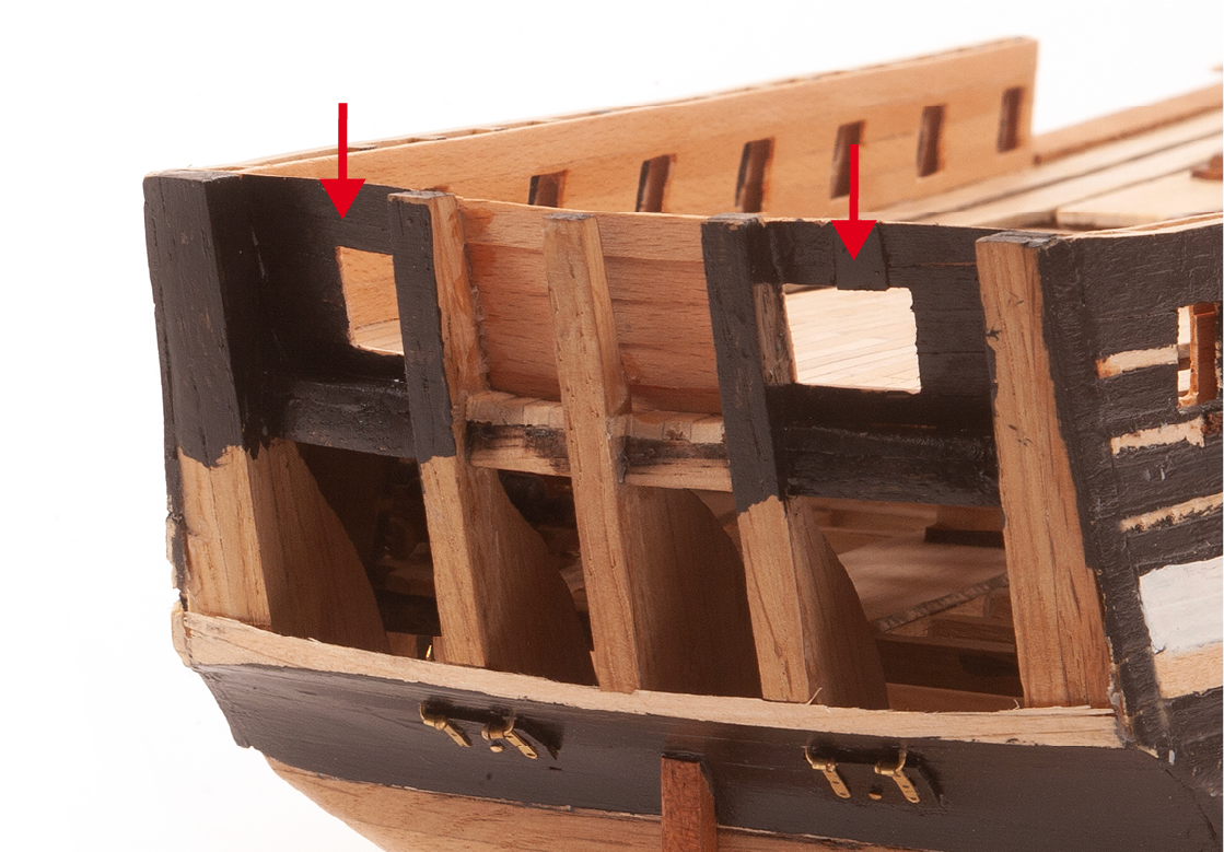
ステップ 11
Cut to size the parts 9.20 and 9.21 from acetate. Sand the parts then paint one side black.
| 9.20: 17 x 17 mm |
| 9.21: 20 x 40 mm |
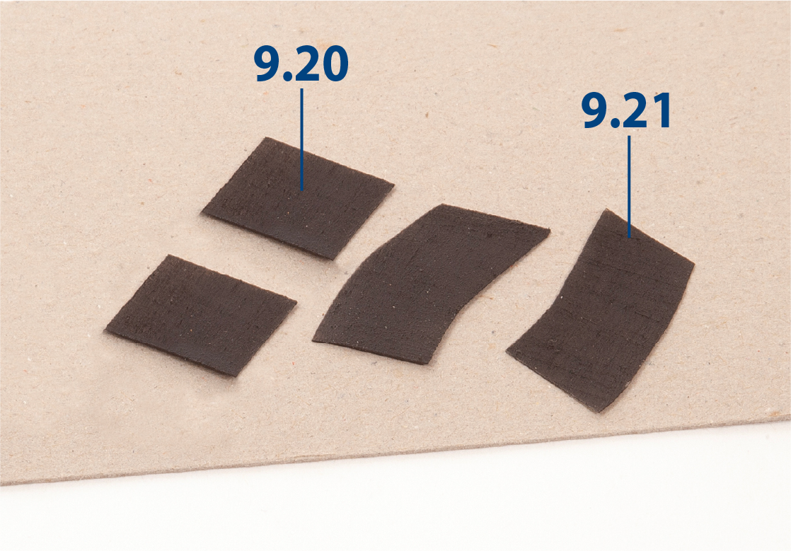
ステップ 12
Glue parts 9.20 to the windows at each end of the transom.
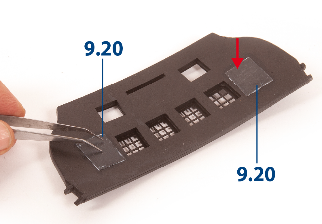
ステップ 1
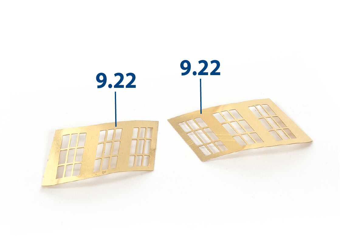
Adjust and bend parts 9.22 to fit the ornaments as shown in the images below, then paint them black.
ステップ 2
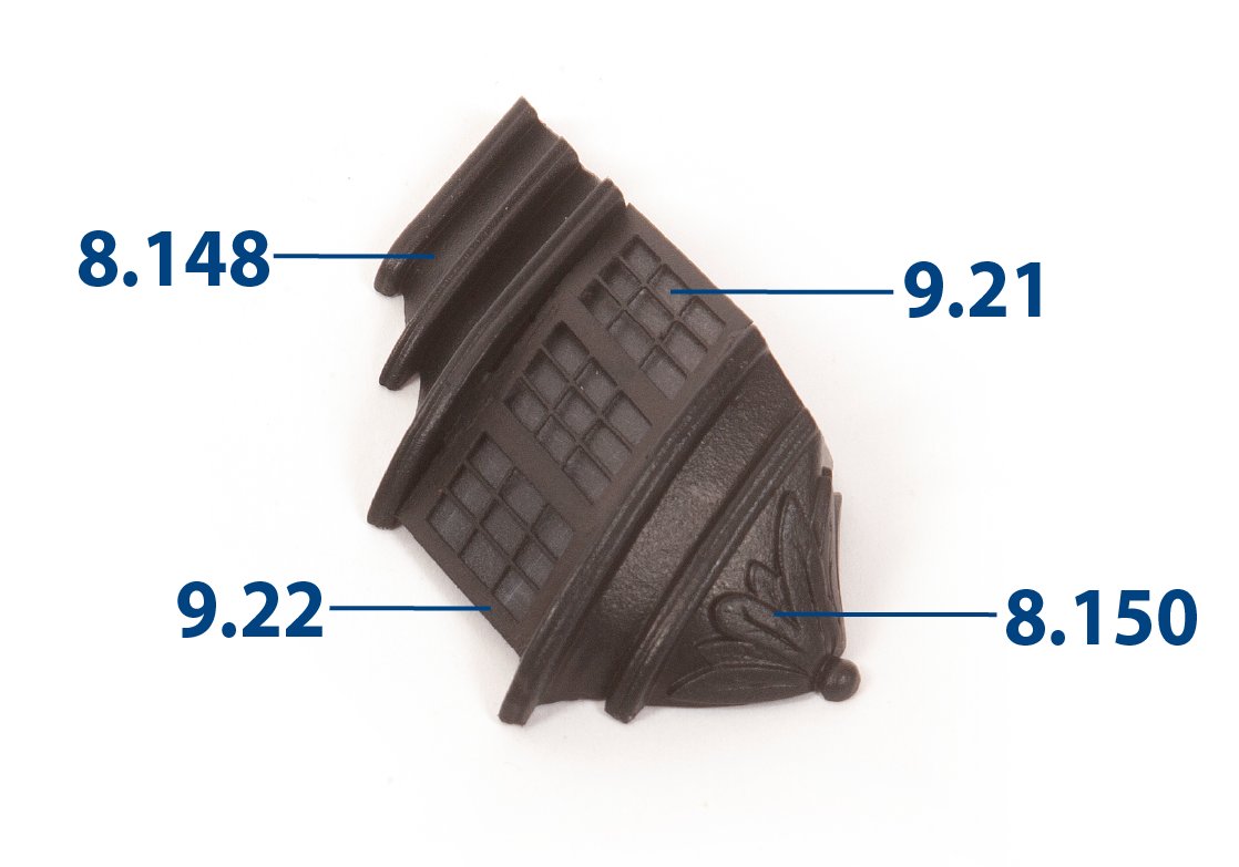
Glue part 9.21 on the inner side of the windows 9.22. Glue parts 8.148 (port gallery crown) and 8.150 (port gallery base) to part 9.22 as shown in the image.
ステップ 3
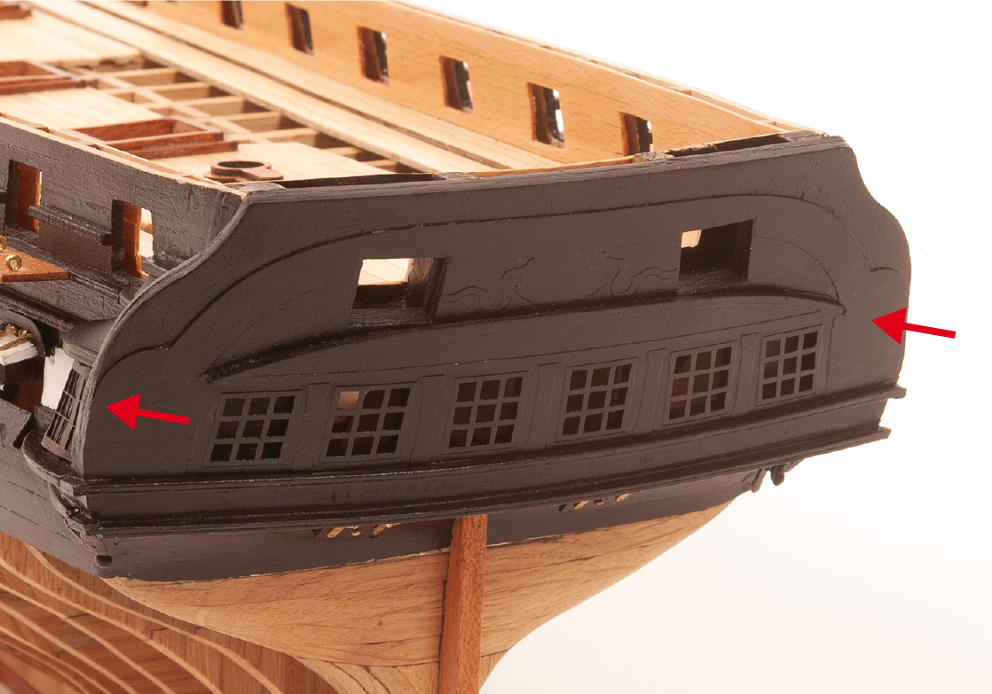
Fit and glue the transom to the hull.
ステップ 4
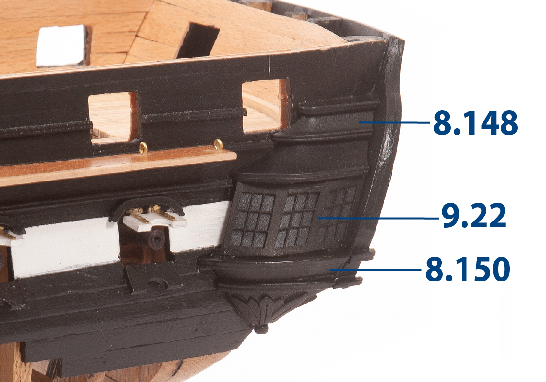
Adjust the gallery crown and gallery base as needed so that they fit the transom, then glue the gallery crown and gallery base to the side of the hull as shown.
ステップ 5
Adjust the column parts 9.23 to 9.26 to fit, paint them white, then glue them in place as shown.
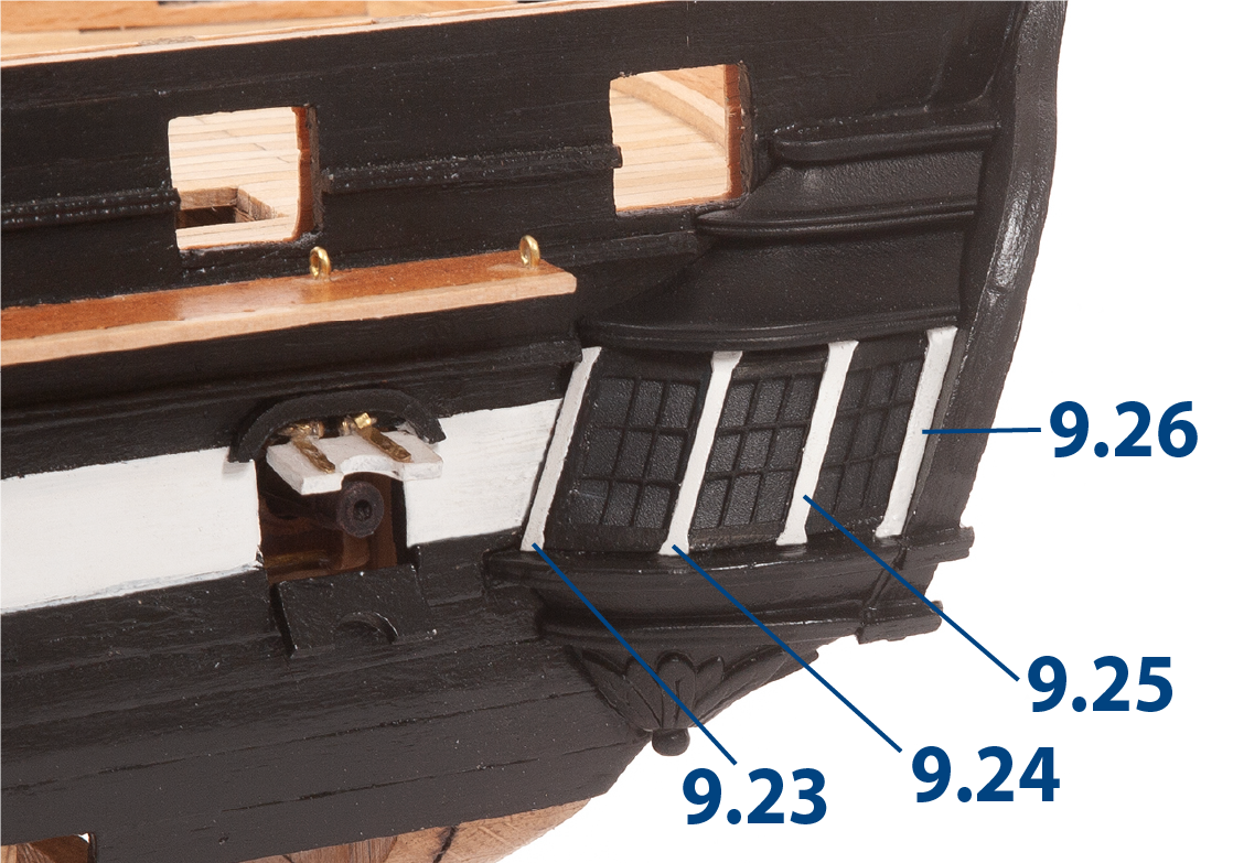
ステップ 6
Repeat steps 1 – 5 to fit the windows to the opposite side of the hull. You can use portions of black painted battens to fill in gaps where needed.
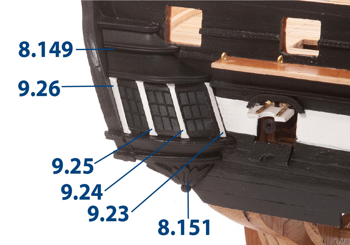
ステップ 7
Glue parts 9.27 on both sides of the hull stem.
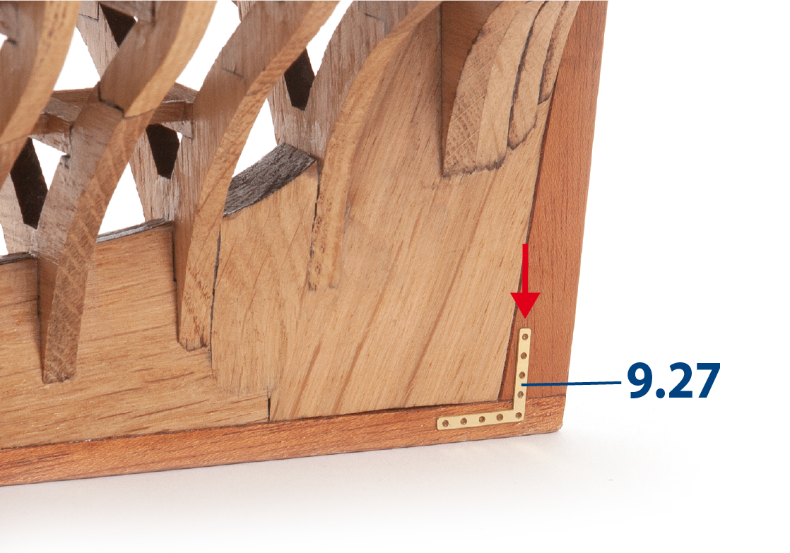
ステップ 8
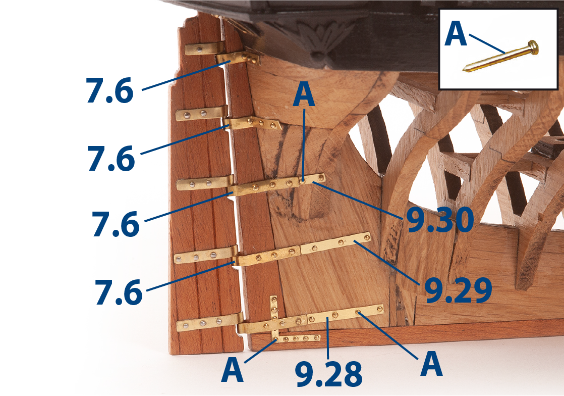
Retrieve the rudder blade that you built in Pack 07. Fit the hinges 7.6 onto the shafts.
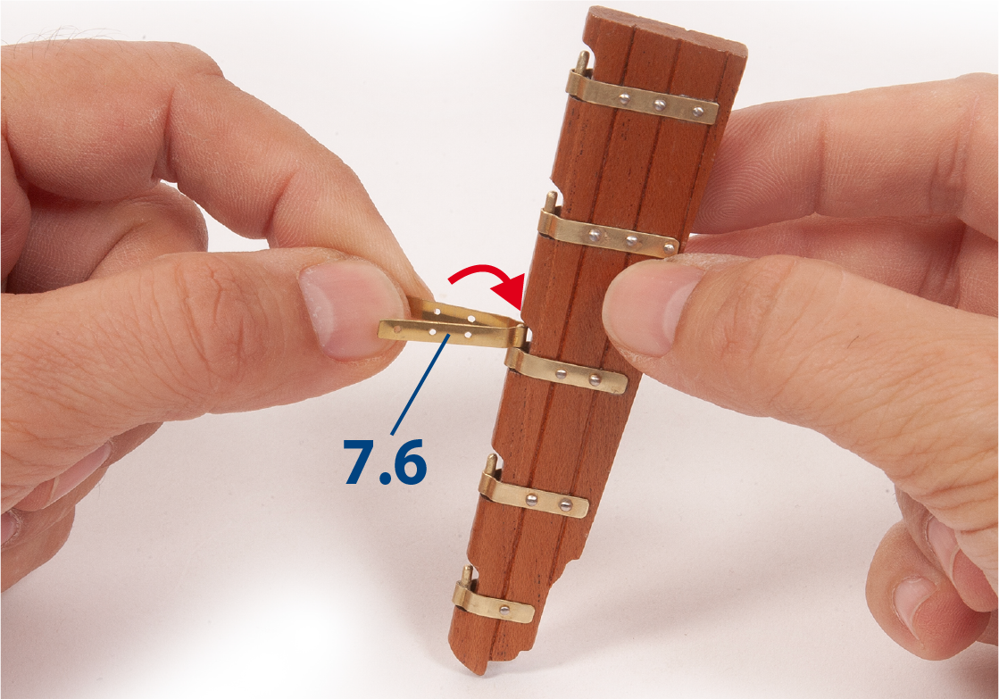
ステップ 9
Adjust and secure the rudder blade to the hull using nails (A). You will need to shape and adjust the parts on the model. Then glue parts 9.28, 9.29, and 9.30 to ensure the continuity of the hinges, before fixing them with nails (A).
ステップ 10
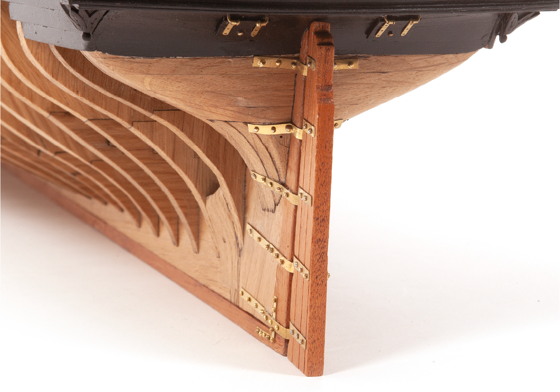
This image shows the hinges in the upper part of the assembly from another angle.
ステップ 11
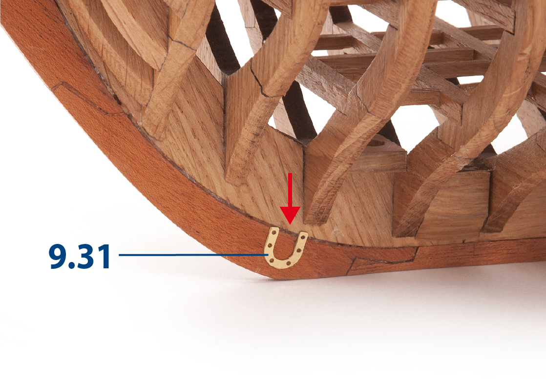
Glue parts 9.31 on both sides of the assembly as shown.
ステップ 12
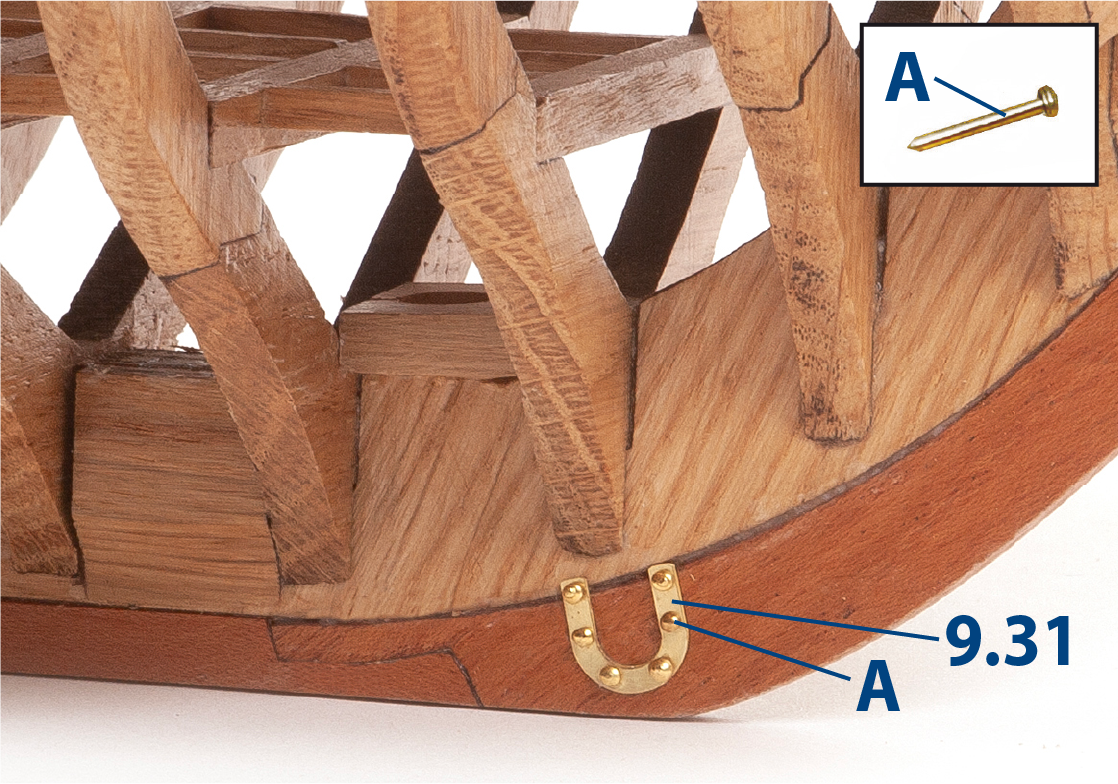
Fit nails (A) to both parts 9.31.
ステップ 13
Make the necessary adjustments so that part 9.32 and part 9.33 (stern ornaments) can be fitted, one on each side of the hull.
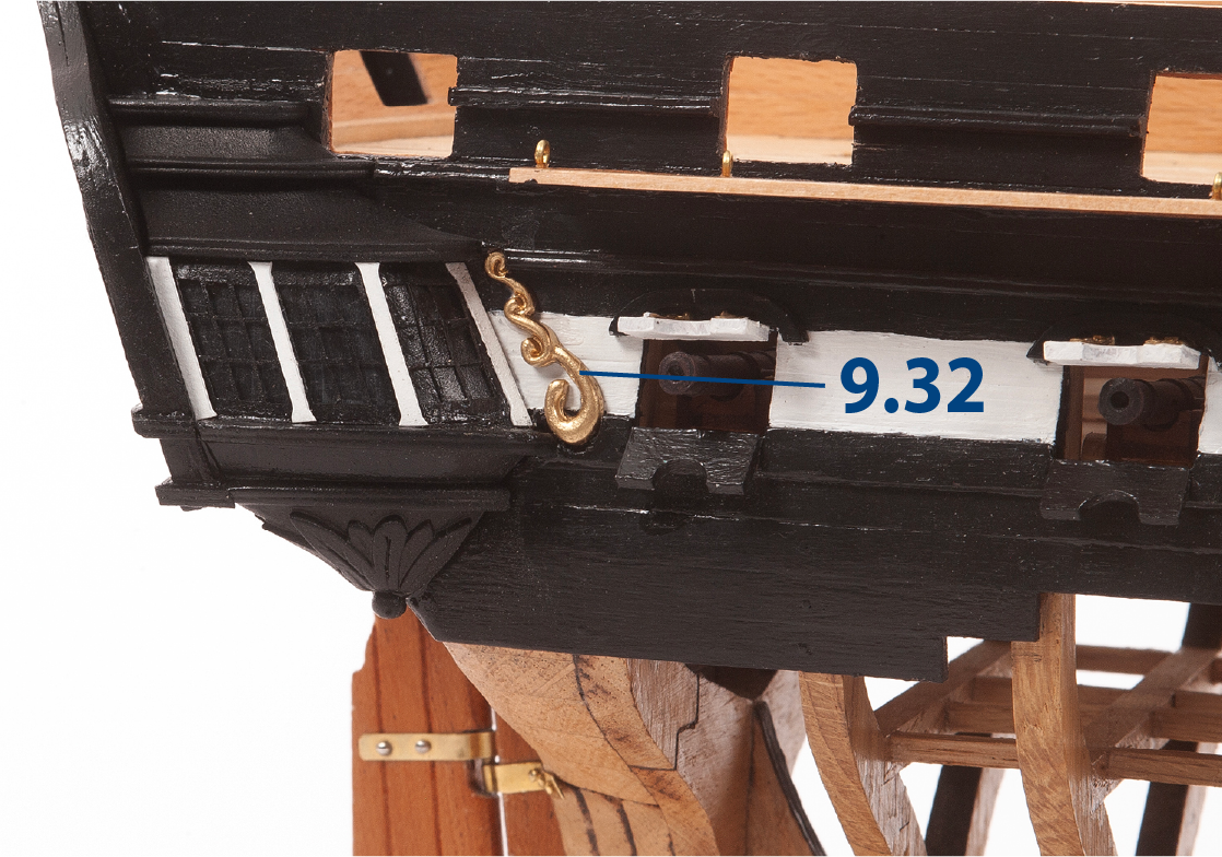
ステップ 14
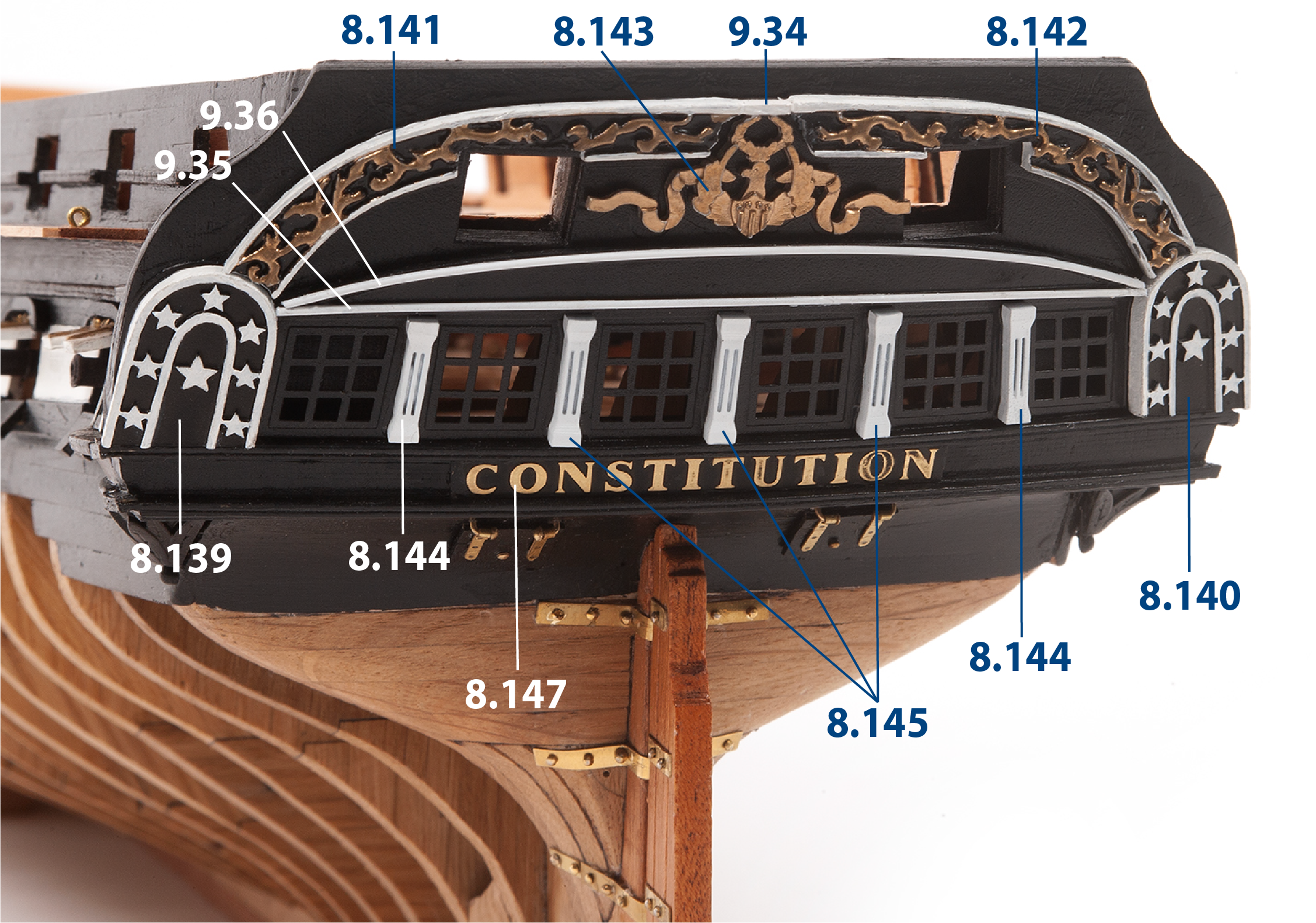
Fit and glue the transom ornaments that were painted in Pack 08 to the transom.
Make parts 9.34 to 9.36 and paint them white, then glue them to the transom.
| 9.34 | 2 x 2 x 6 mm lime wood |
| 9.35 | ø1 x 114 mm brass |
| 9.36 | ø1 x 118 mm brass |
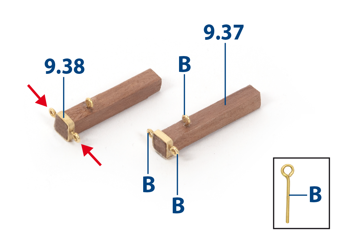
ステップ 1
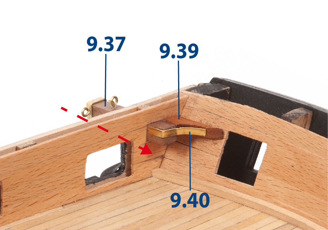
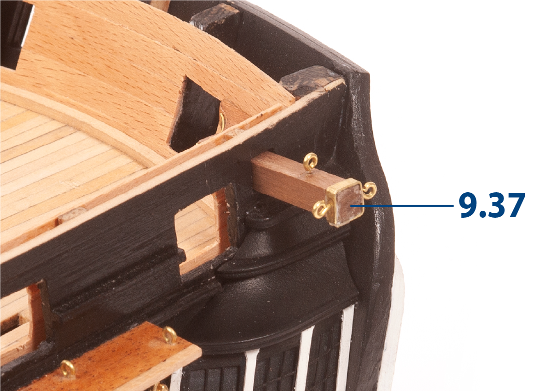
Assemble the two davits using parts 9.37 (6 x 6 x 32 mm African walnut) and 9.38 (2 x 24 mm brass), then drill ø0.75 mm holes to fit eyebolts (B) as shown.
ステップ 2
Using the whole ship elevation drawing as a guide, drill and cut the holes for the davits.
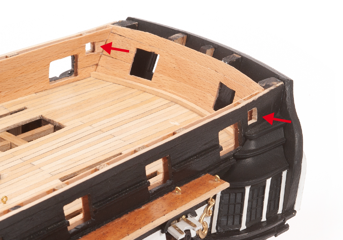
ステップ 3
Insert a davit, fit part 9.39, then glue in place. Cut to length part 9.40 (2 x 21 mm brass) and glue as shown in the image.
ステップ 4
Proceed in the same way to attach the parts on the other side of the hull.
ステップ 5
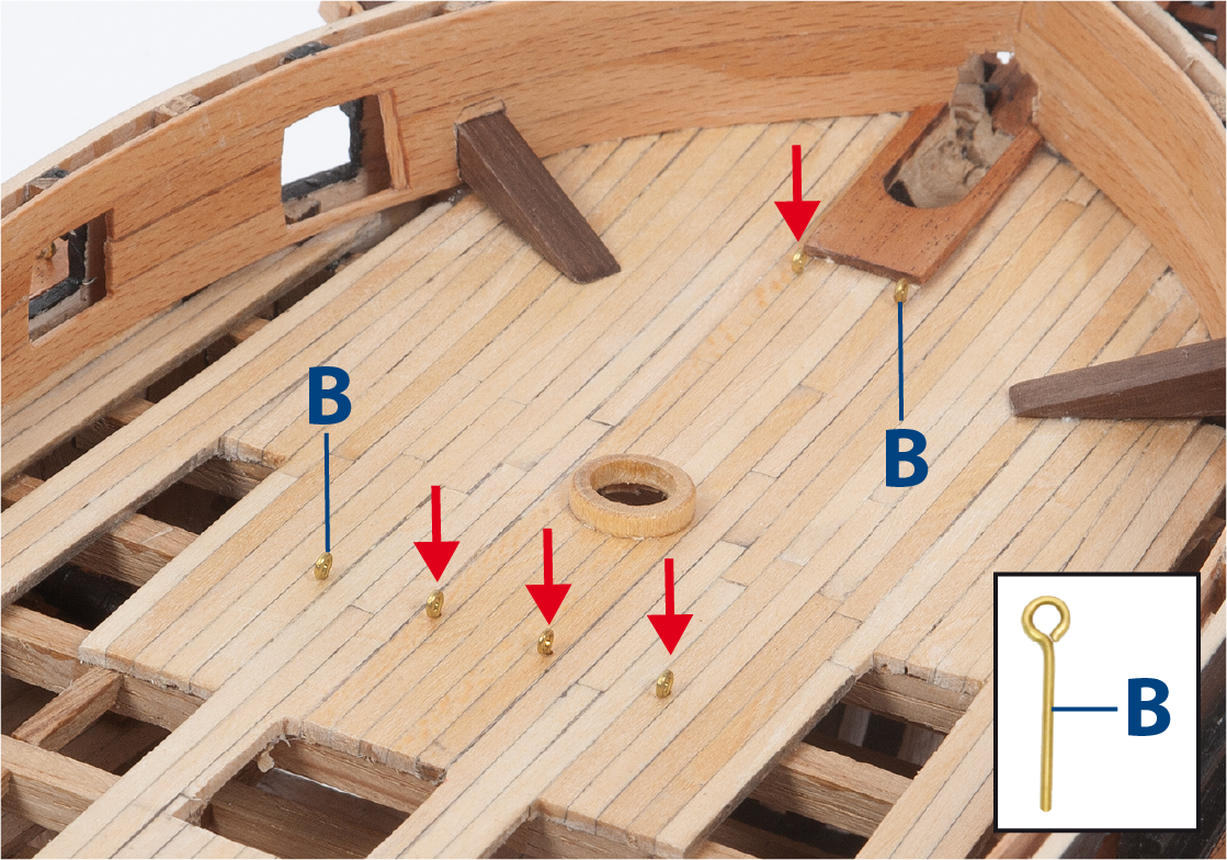
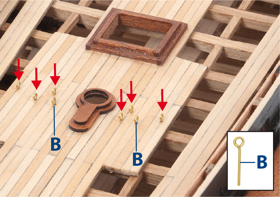
Using the deck plan, insert and fix the eyebolts (B), as shown.
ステップ 6
Continue to fit the eyebolts (B) as shown.
ステップ 7
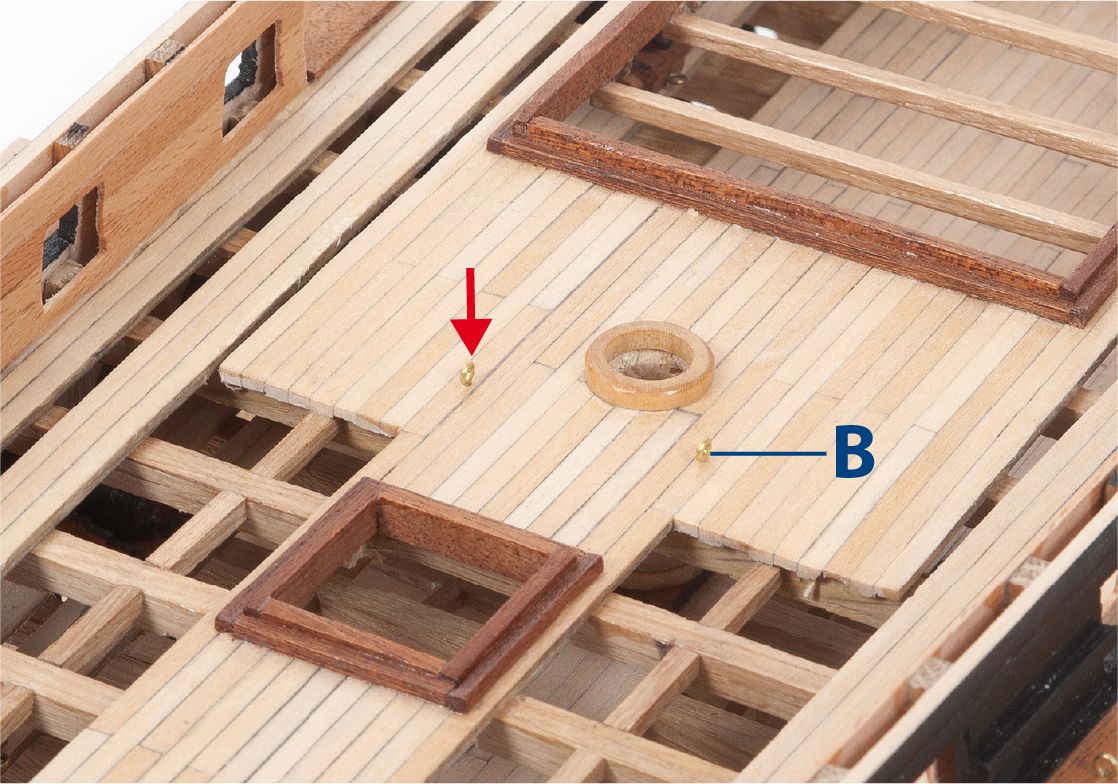
Fit the eyebolts (B) in the mizzenmast area as shown.
ステップ 8
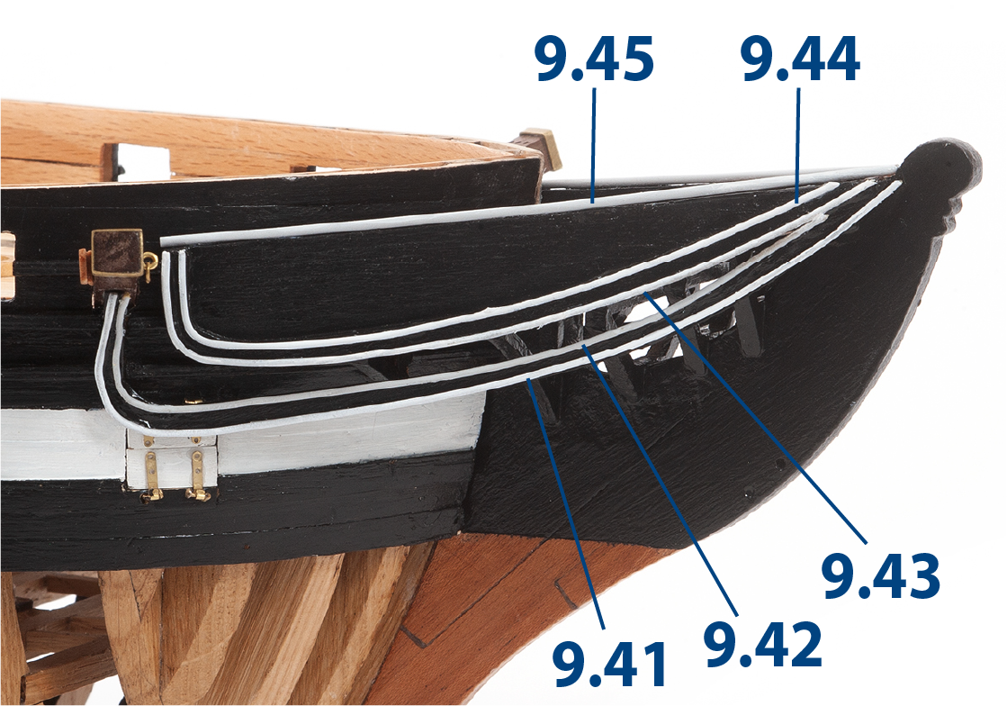
Cut brass wire to the lengths shown below, then paint them white and glue to the hull as shown. Repeat this step on the other side of the hull.
| 9.41: ø1 x 137 mm | 9.44: ø1 x 133 mm |
| 9.42: ø1 x 135 mm | 9.45: ø1.5 x 55 mm |
| 9.43: ø1 x 135 mm |

ステップ 9
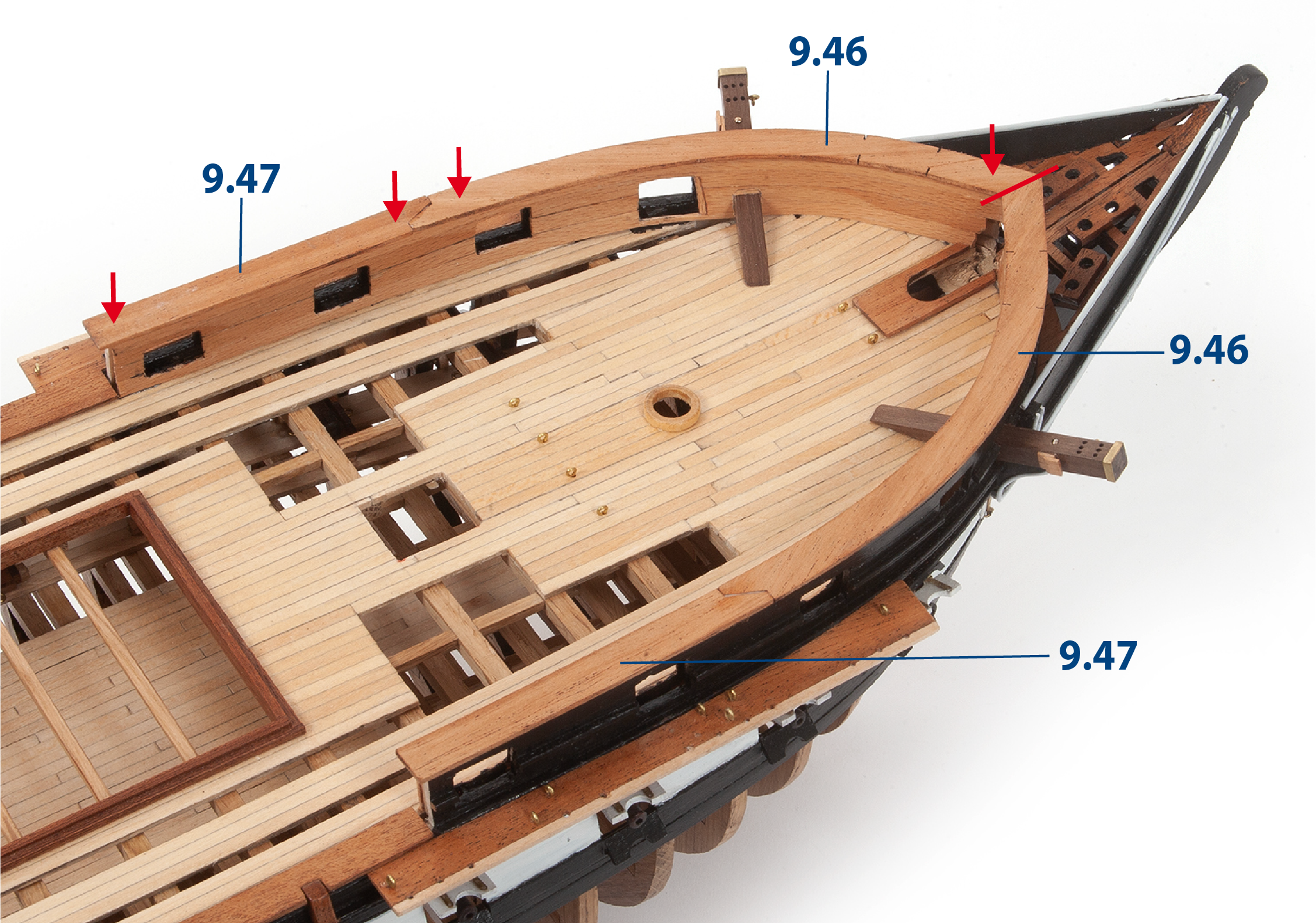
Fit and glue parts 9.46 and 9.47 on both sides of the hull.
ステップ 10
This image shows the hull with the bow parts in place.
ステップ 1
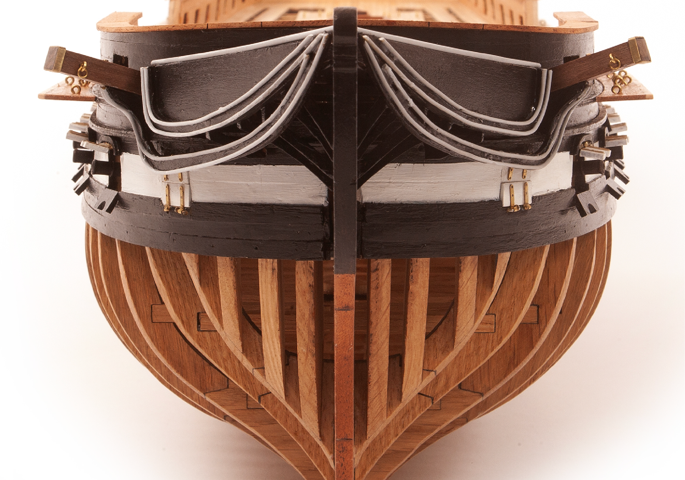
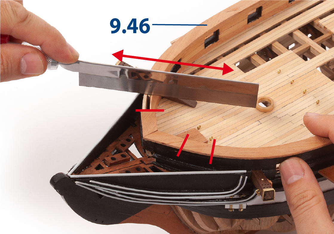
Cut parts 9.46 at the laser marks.
ステップ 2
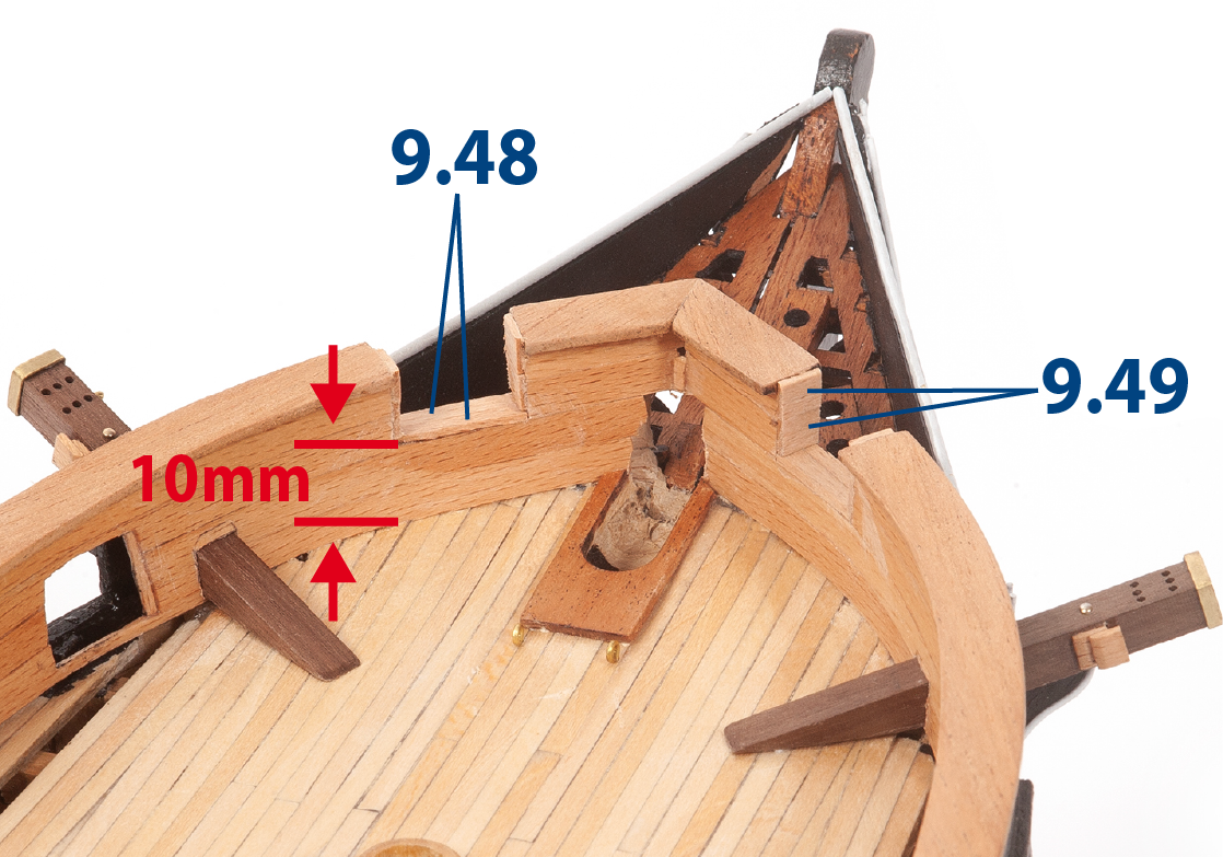
Cut out the openings as shown in the image. Cut parts 9.48 (1 x 5 x 10 mm lime wood) and 9.49 (1 x 5 x 8 mm lime wood) to size, then glue them in place to line the edges of the openings.
ステップ 3
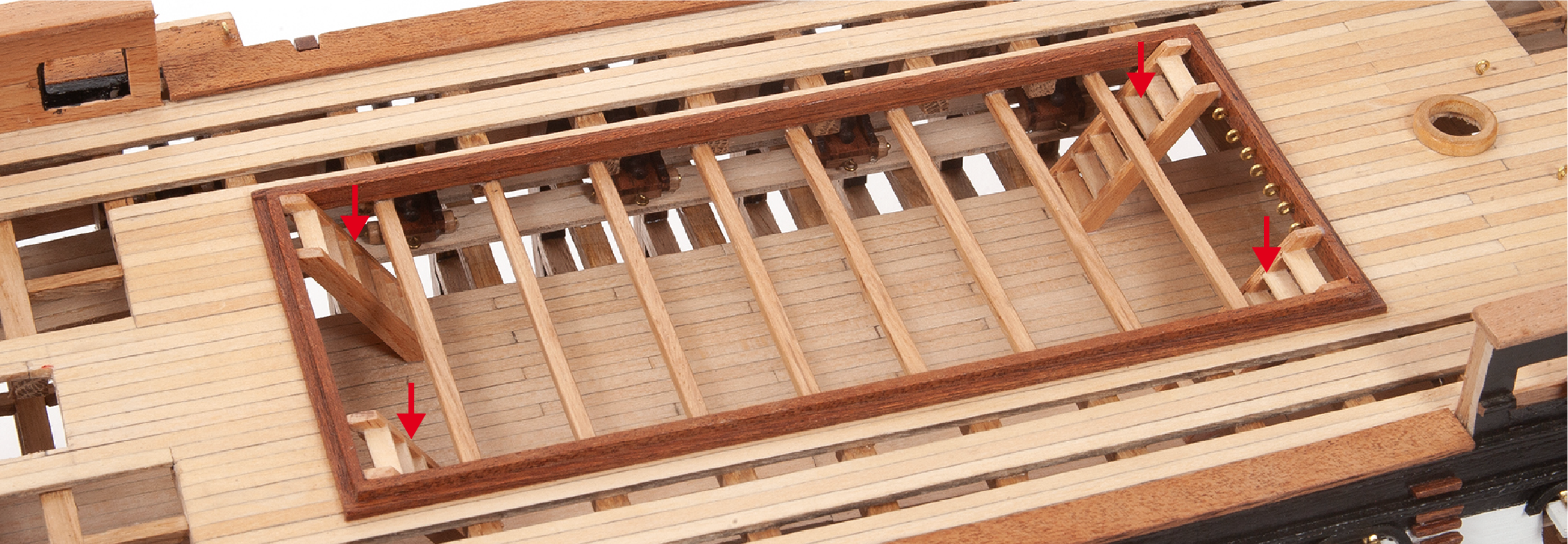
Retrieve the wide ladders you built previously. Check their fit and adjust their height if needed, then glue them in place, referring to the deck plan.
ステップ 4
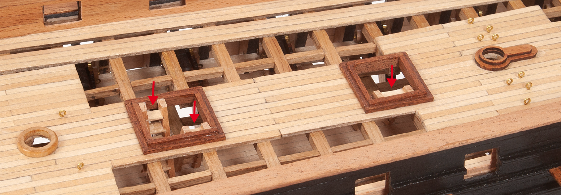
Fit and glue the three remaining ladders in the aft area as shown on the deck plan.
ステップ 5
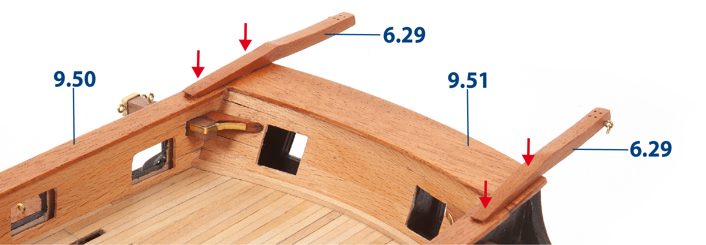
Referring to the plan and the images below, fit and glue parts 9.50 and 9.51, then glue in place the davits 6.29 that you built in Pack 06.
The image below shows the davits installed upside down. Please refer to your plan for correct installation.
ステップ 6
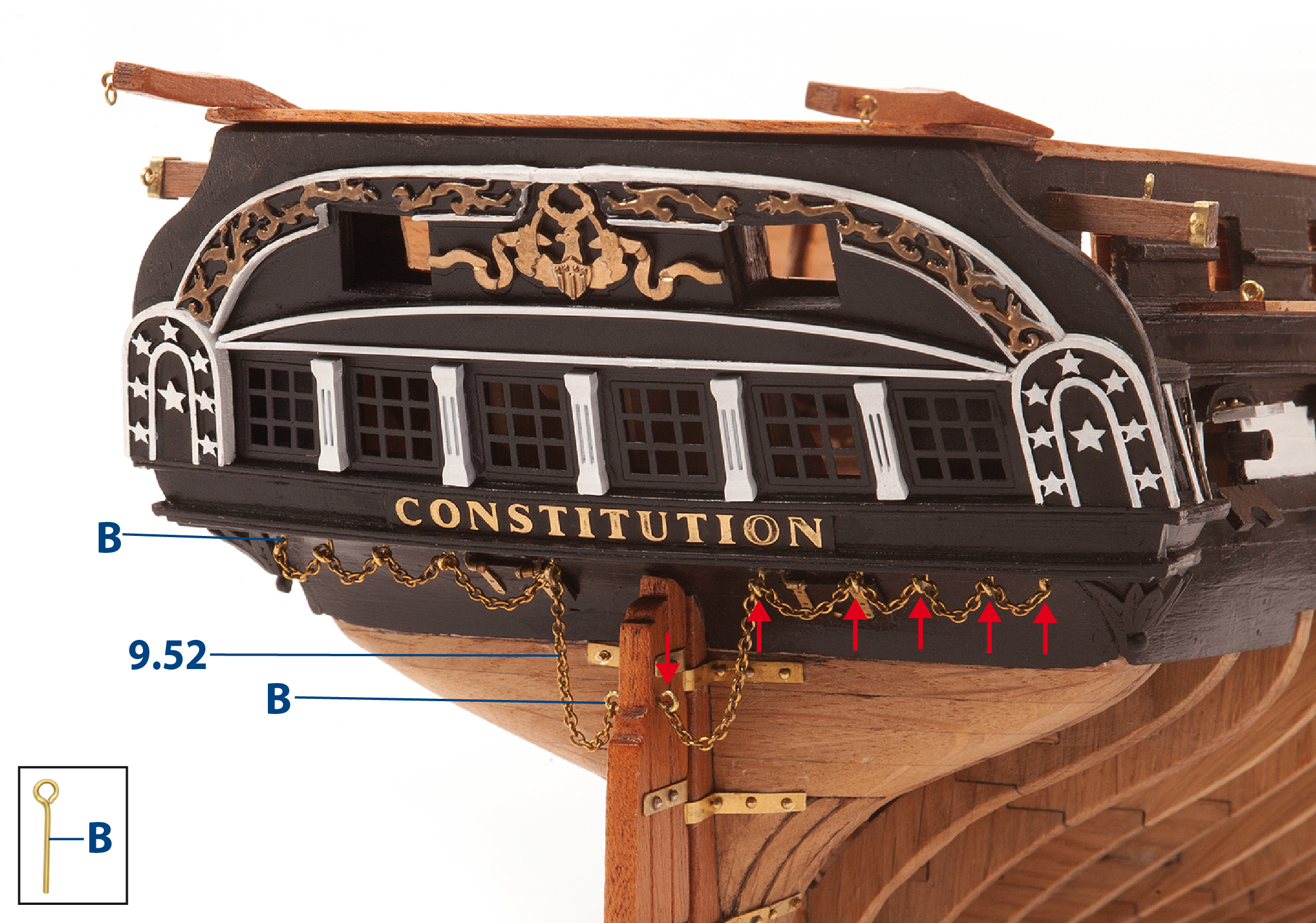
Drill the holes to insert the eyebolts B. Attach the chain 9.52 (1 x 300 mm) to the eyebolts as shown in the picture.
ステップ 1
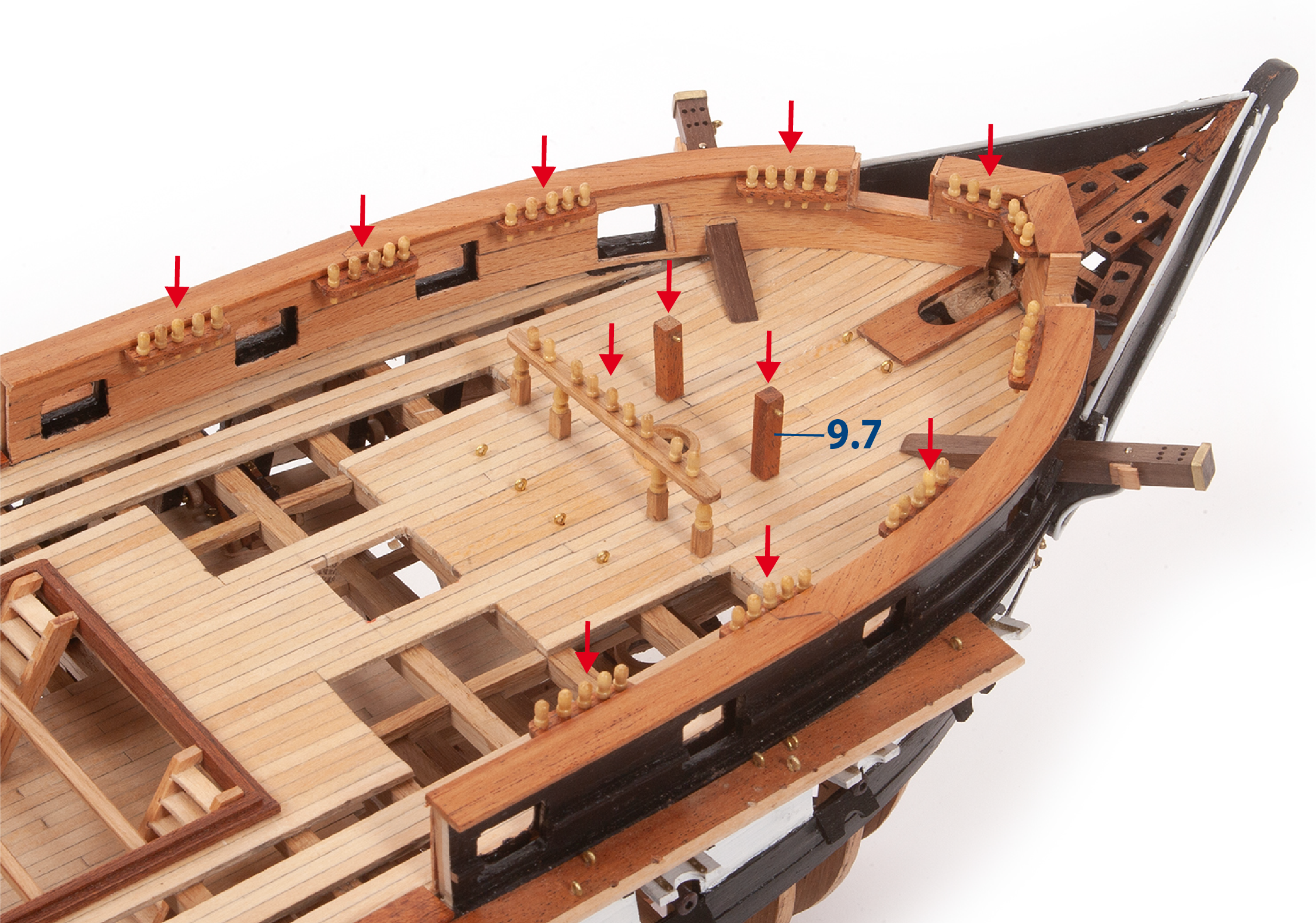
Retrieve the pin rails built in Pack 06 and fit them, referring to the deck plan. Then fit parts 9.7 onto the deck as shown.
ステップ 2
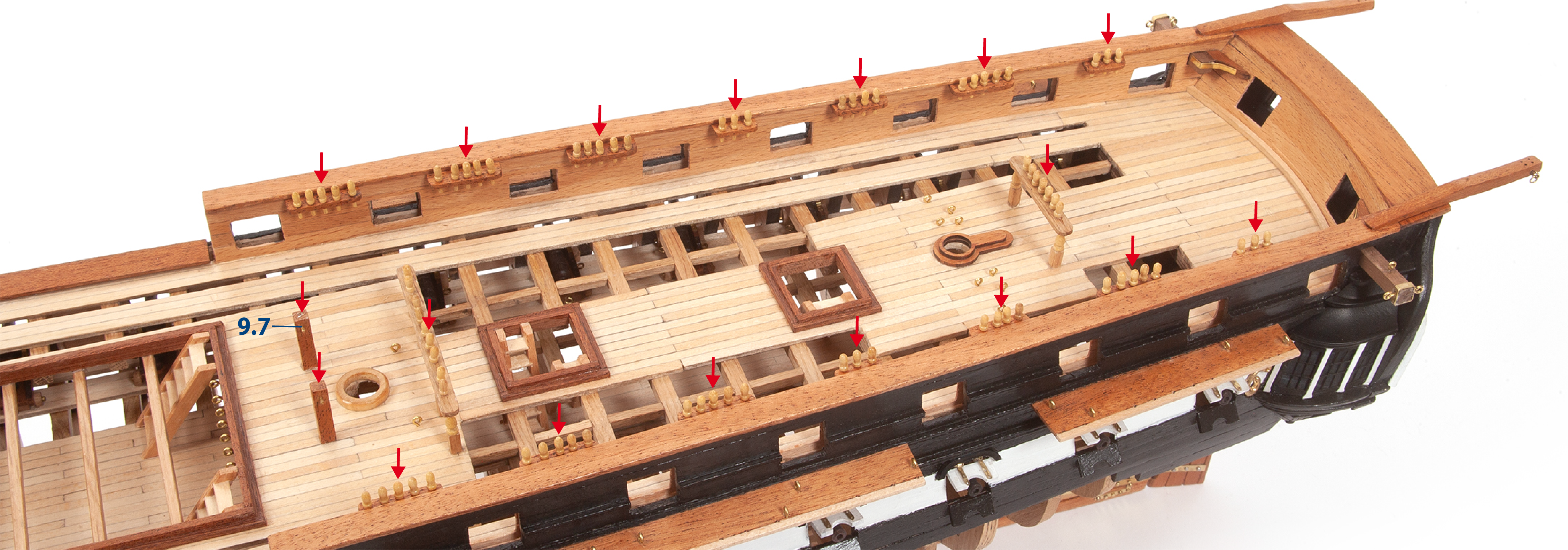
Continue to fit the pin rails to the assembly as shown in the image.
ステップ 3
This is how the ship looks once this pack has been completed.