Zásilka 03
NÁVOD NA STAVBU
Návod na stavbu vašeho modelu lodi U.S.S. Constitution
Váš model lodi U.S.S. Constitution je rozdělen do 12 zásilek.
Budete muset postupovat podle krok za krokem fotografií sestavení, plánů a vysvětlujících textů níže.
Prosím, uschovejte zbylé materiály z každé zásilky pro použití, když vás k tomu instrukce později vyzvou.
Zobrazené IP listy níže jsou kresby dílů vyřezávaných laserem a foto-leptaných mosazných dílů a poslouží jako průvodce pro identifikaci některých dílů.
Použijte tabulku PŘEHLED DÍLŮ, aby vám pomohla lokalizovat díly.
Šablony PL-00 (tištěné v měřítku 1/1), které jsou součástí každé zásilky, poslouží jako průvodce pro stavbu žebříků.
Prosím, zkontrolujte níže uvedený seznam, abyste se ujistili, že máte všechny nástroje potřebné pro stavbu vaší dřevěné lodi.
Při odstraňování dílu odřízněte žebra, která spojují díl s dřevěnou deskou, pomocí řezáku.
Odstraňujte díly opatrně, aby nedošlo k jejich poškození.
Uchovávejte a skladujte díly ve svých rámech. Odstraňujte pouze díly, na kterých pracujete v každém kroku.
Další podporu naleznete na našem fóru nebo na stránce Adresář odborníků naší webové stránky.
SEZNAM DÍLŮ
| Materiál | Množství | |
| Dřevěné Planžety 2001-17 – 2001-19 | Dřevo | 3 |
| Dřevěné lišty | ||
| 5 x 5 x 400 mm | Dub | 14 |
| 3 x 3 x 400 mm | Lípa | 7 |
| 2 x 5 x 600 mm | Lípa | 10 |
| Tyče (ø 10 mm x 450 mm) | Mahagon | 1 |
| Ostatní díly | ||
| Kroužek (pro stěžeň MT24 – ø 10 mm) | 6 | |
| Kroužek (pro stěžeň MT125 – ø 8 mm) | 2 | |
| Šablony | ||
| Montážní šablona PL-06 | 1 |
Nástroje, které budete potřebovat: podložka na stříhání, tužka, řezací nůž, smirkový papír s jemným zrnem nebo brusná houbička, pilník, bílé lepidlo na dřevo, sekundové lepidlo (kyanokrylátové lepidlo), maskovací páska, pravítko, pilka na kov, brusný blok, ocelové pravítko 30 cm, svěrky, mikroprofilovače
ZÁSILKA 03 IDENTIFIKAČNÍ LISTY
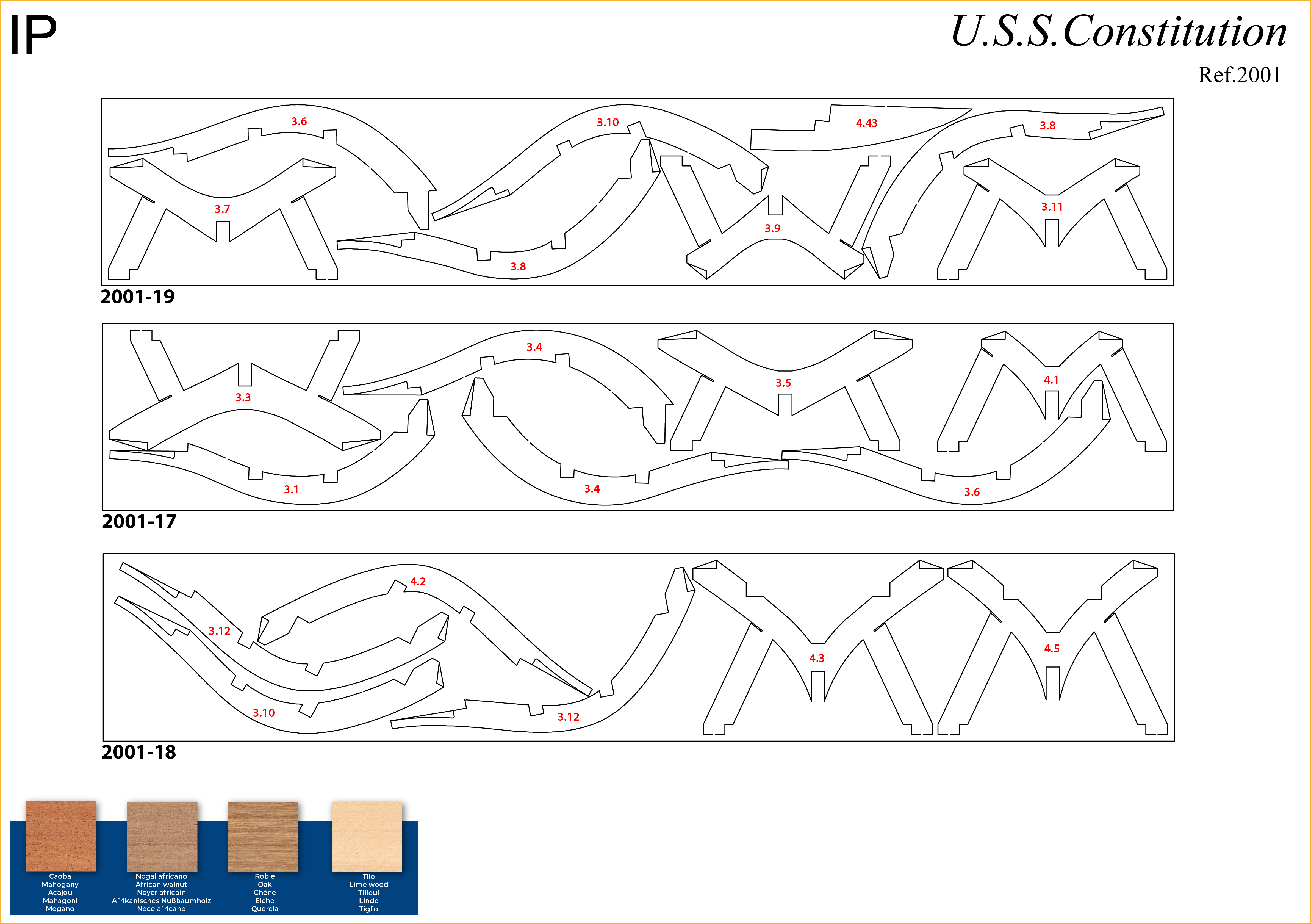
PŘEHLED DÍLŮ
ČÍSLO DÍLU | UMÍSTĚNÍ NA IP-ARCHU | ČÍSLO DÍLU | UMÍSTĚNÍ NA IP-ARCHU |
| 3.1 | 2001-13 + 2001-17 | 3.8 | 2001-19 |
| 3.2 | 2001-13 | 3.9 | 2001-19 |
| 3.3 | 2001-17 | 3.10 | 2001-18 + 2001-19 |
| 3.4 | 2001-17 | 3.11 | 2001-19 |
| 3.5 | 2001-17 | 3.12 | 2001-18 |
| 3.6 | 2001-17 + 2001-19 | 3.26 | 2001-11 |
| 3.7 | 2001-19 |
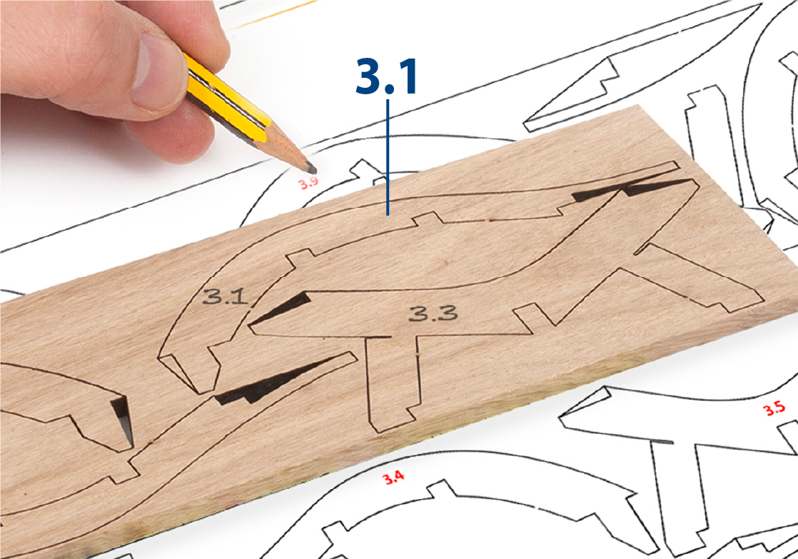
Krok 1
Použijte tužku k přenesení čísel z IP-ARCHU na dřevěné planžety.
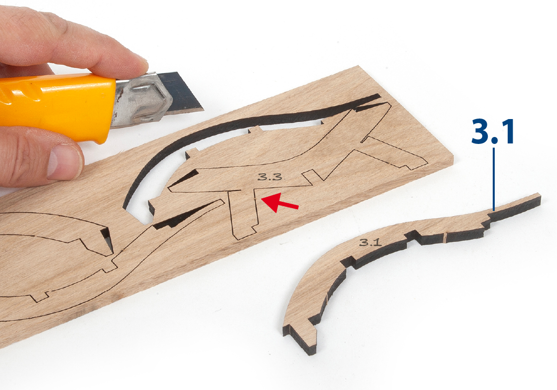
Krok 2
Řežte žebra, která spojují díly s pláty pomocí řezáku, aby bylo možné je odstranit bez poškození. Odstraňujte pouze ty části, na kterých pracujete v každém kroku.
Krok 3
Umístěte díly na rovný povrch a obrousit je jemným smirkovým papírem nebo brusnou houbičkou.
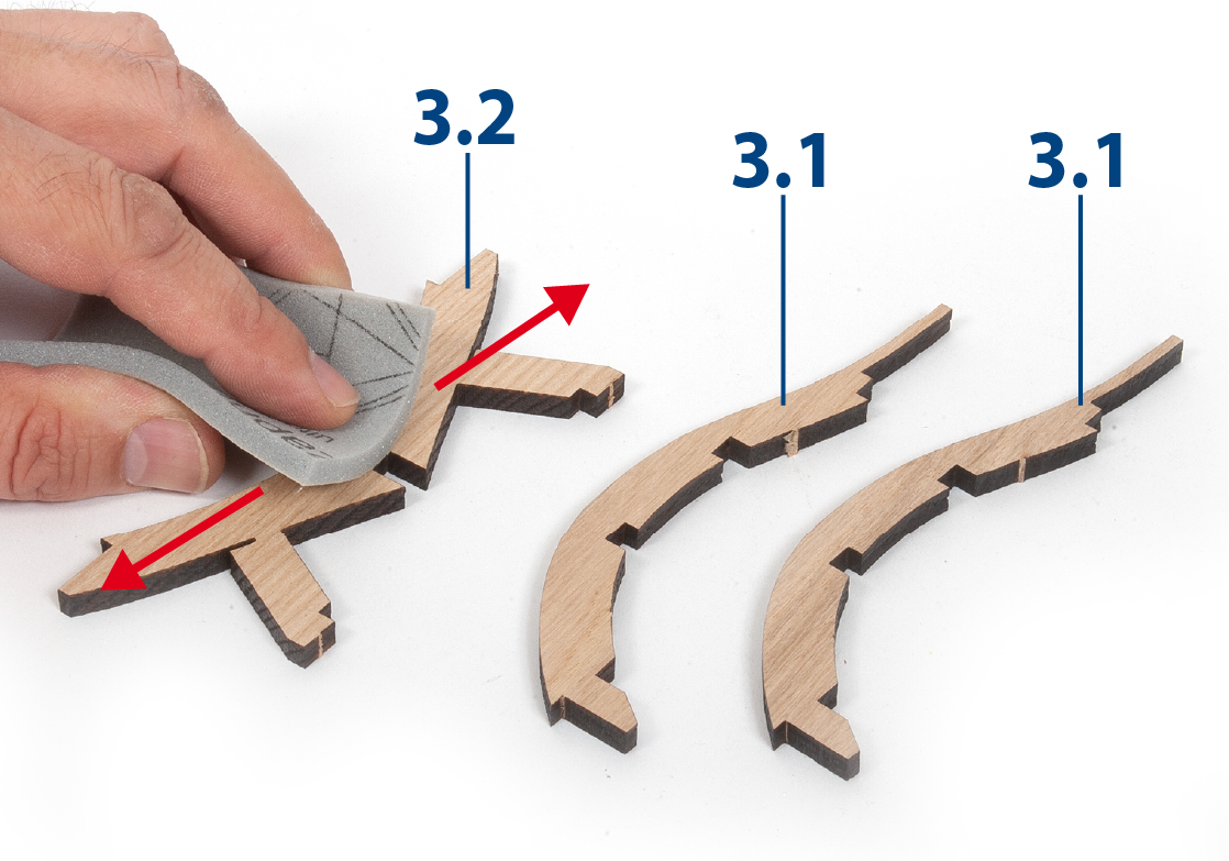
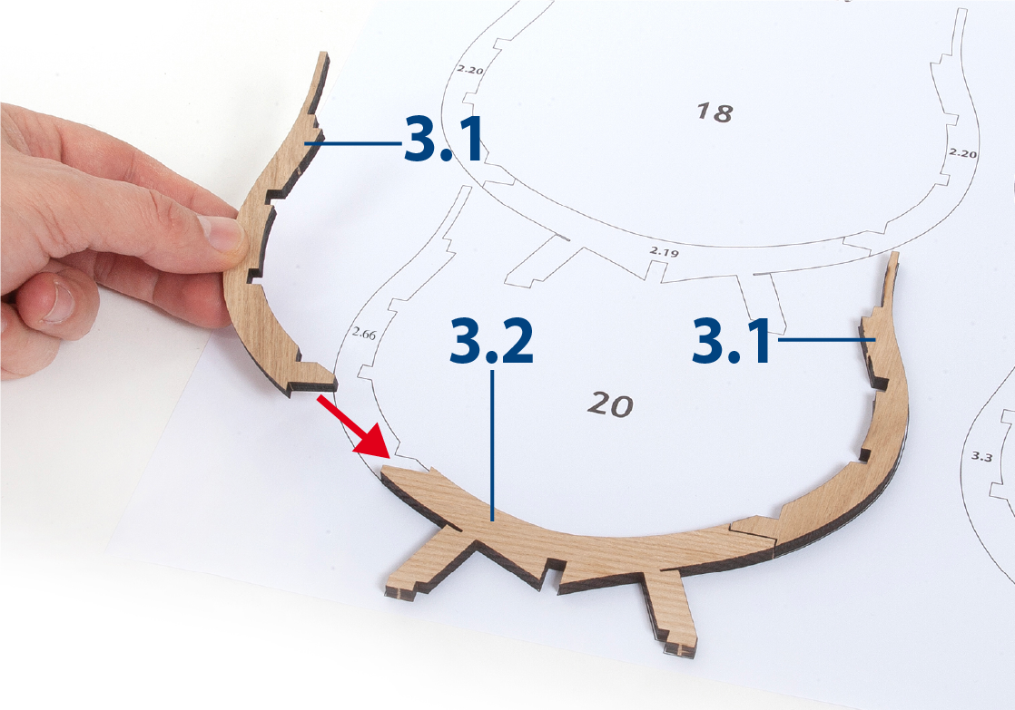
Krok 4
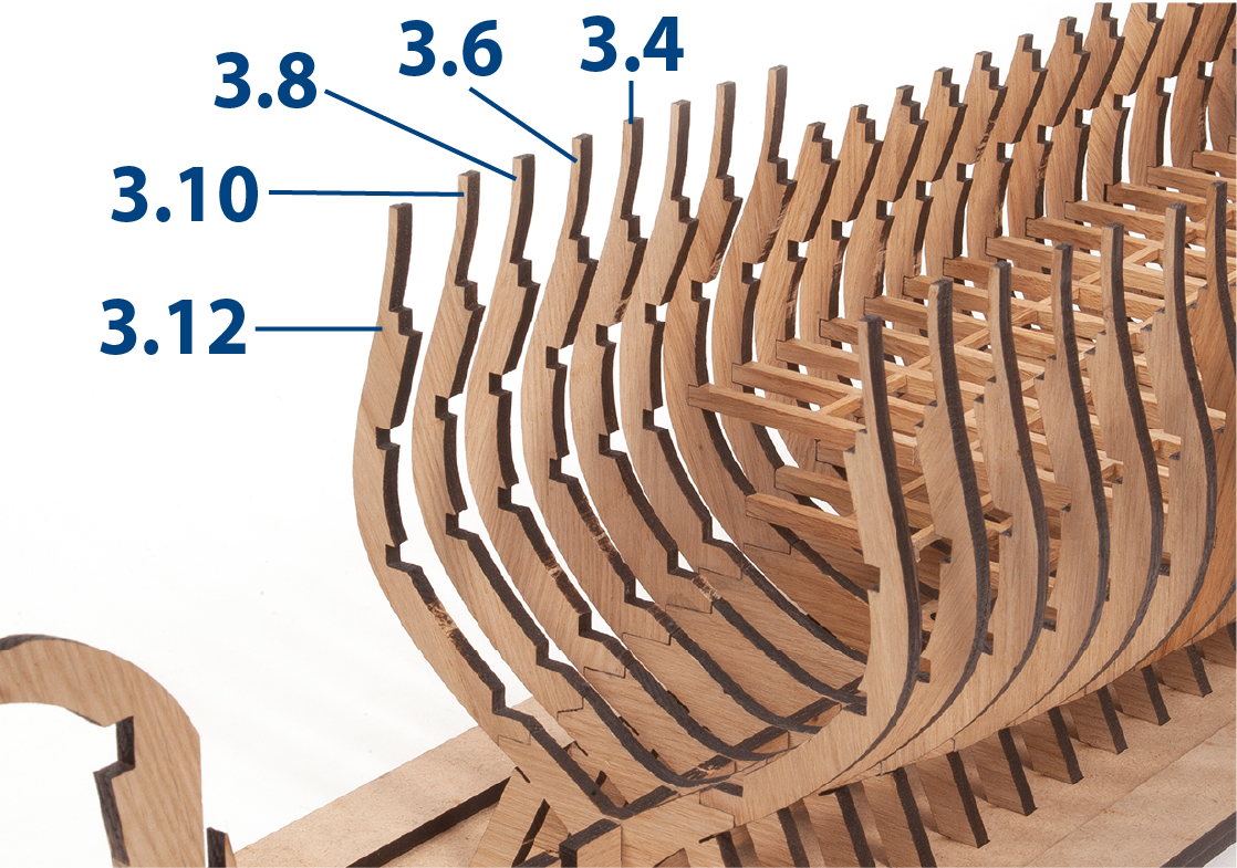
Umístěte díly 3.1 a 3.2 na obrázek žebra 20, abyste zkontrolovali jejich pasování, a poté díly slepte dohromady.
Krok 5
Sestavte žebra 20 až 25 s šablonami PL-05 a PL-06.
Krok 6
Vložte a slepte žebro 20 do rámu.
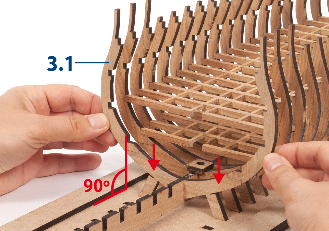
Krok 7
Postupujte stejným způsobem při vkládání a lepení žeberek 21 až 25.
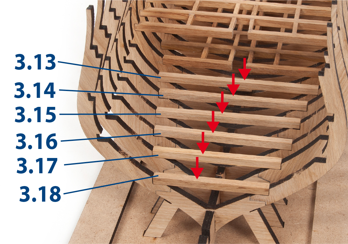
Krok 8
Řežte části 3.13 až 3.18 na délku (5 x 5 mm) a lepte je do spodních prohlubní žeberek.
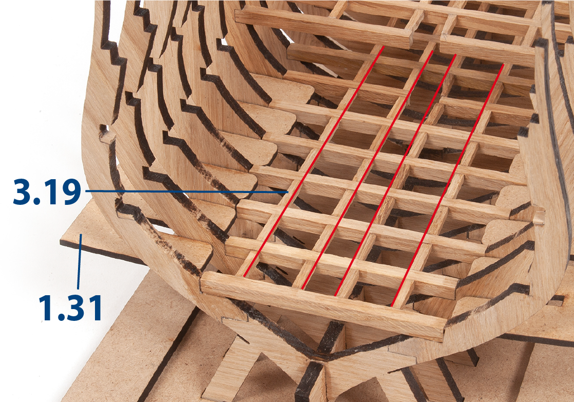
Krok 9
Vložte, bez lepení, díly 1.31, jeden na každou stranu žebra.
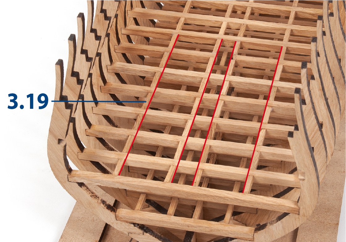
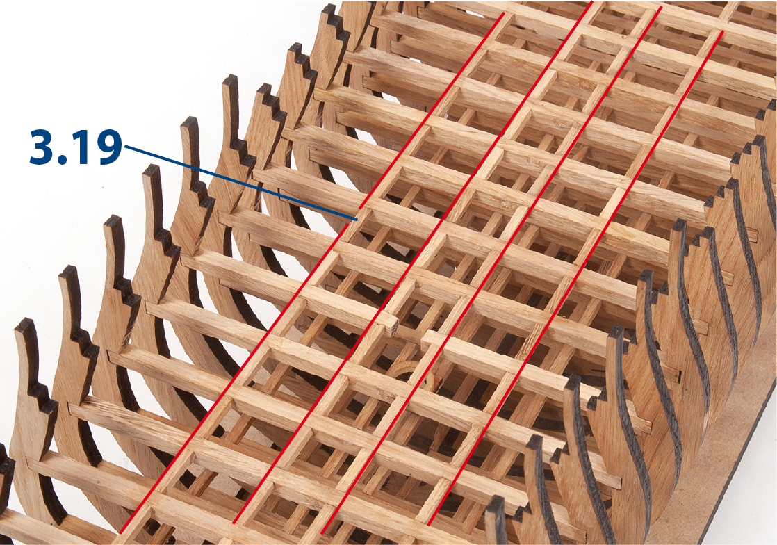
Nastříhejte díly 3.19 (3 x 3mm) na délku a nalepte je v kontinuitě s již umístěnými.
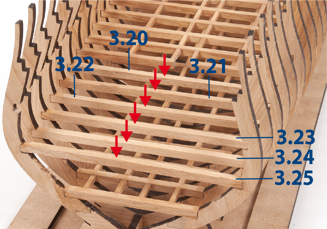
Krok 10
Nastříhejte na délku a slepte díly 3.20 až 3.25 (5 x 5mm).
Krok 11
Vložte, bez lepení, díly 1.31, jeden na každou stranu žebra.
Nastříhejte na velikost a slepte díly dohromady 3.19 (3 x 3mm). Doporučuje se použít bílé lepidlo pro slepení dřevěných částí.
Krok 12
Montáž stěžňů
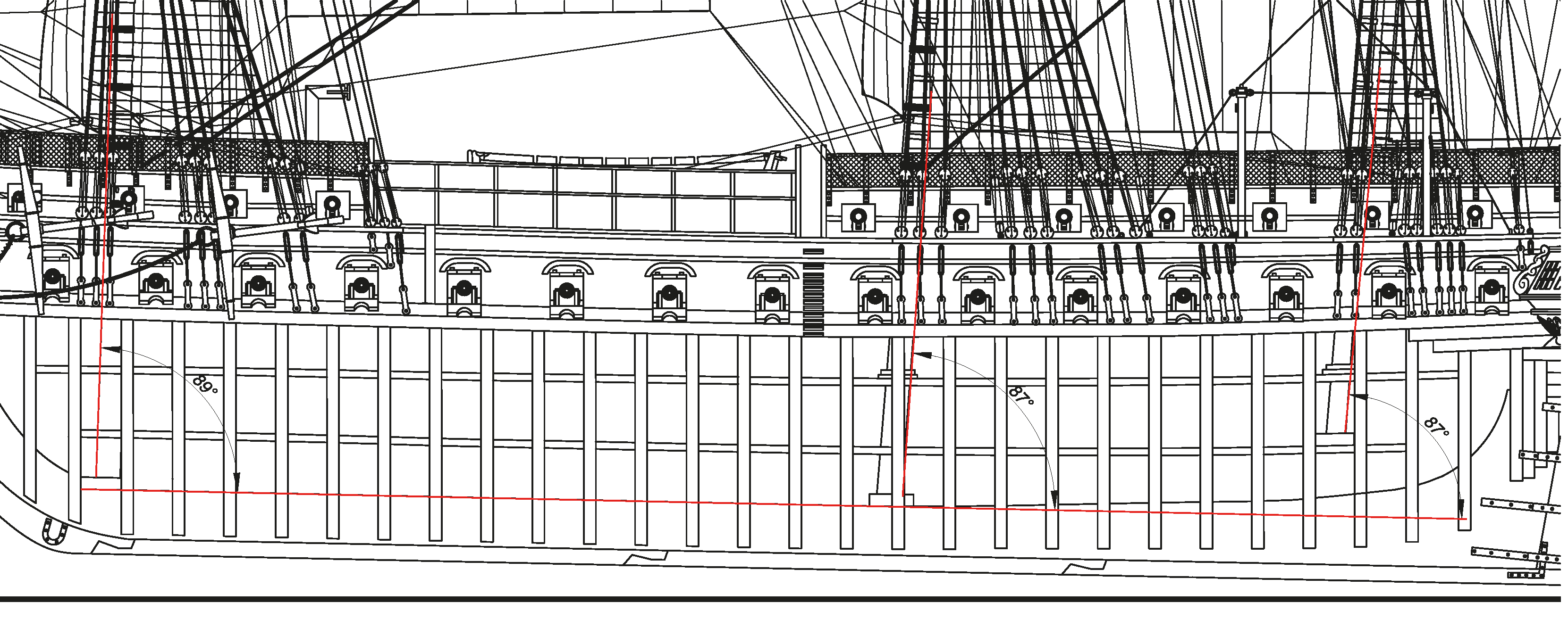
Nyní začnete montovat komponenty pro stěžně. V Zásilka 5 obdržíte výkres v měřítku 1:1, který detailně zobrazuje loď.
Tento obrázek je částí výkresu ukazující stěžně spolu s jejich úhly vůči trupu jako referenci. Vezměte prosím na vědomí, že zde zobrazené úhly jsou pouze orientační a mohou se mírně lišit podle montáže dílů na vašem individuálním modelu.
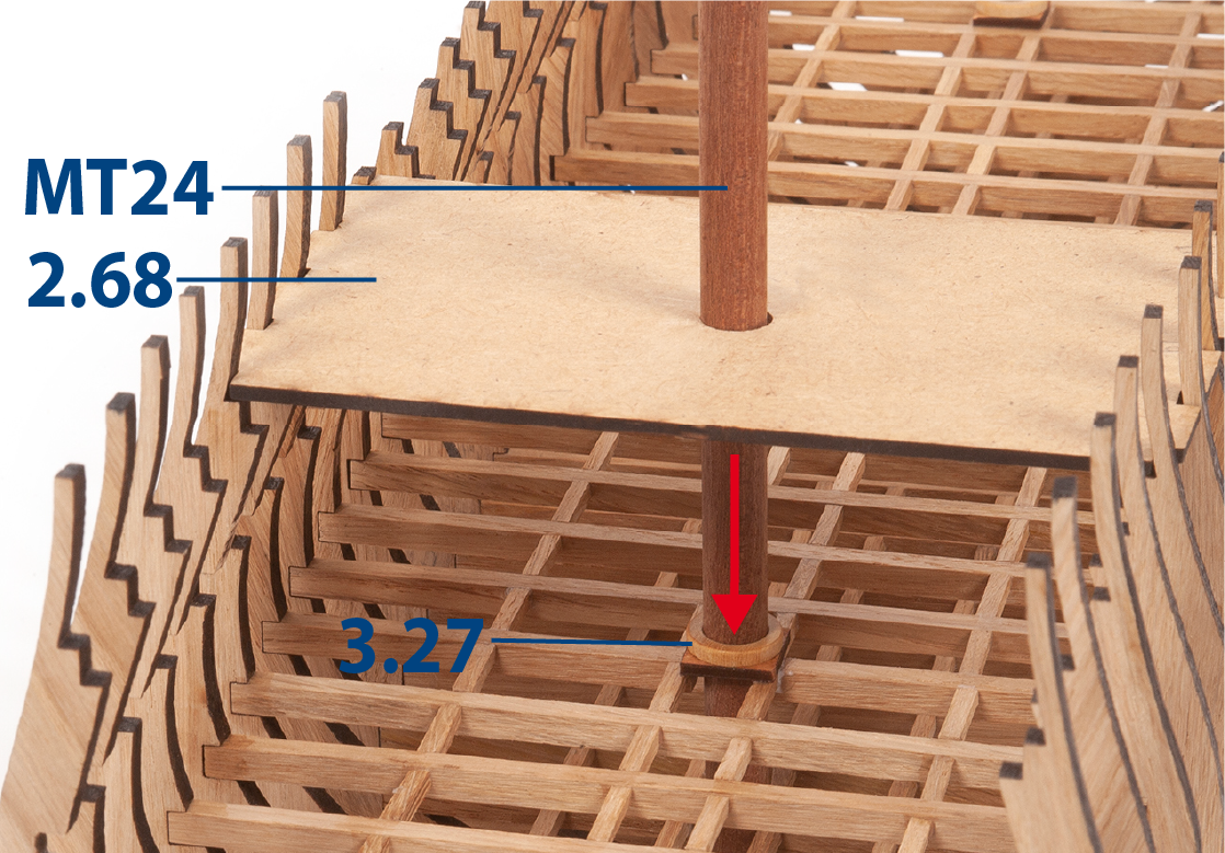
Krok 13
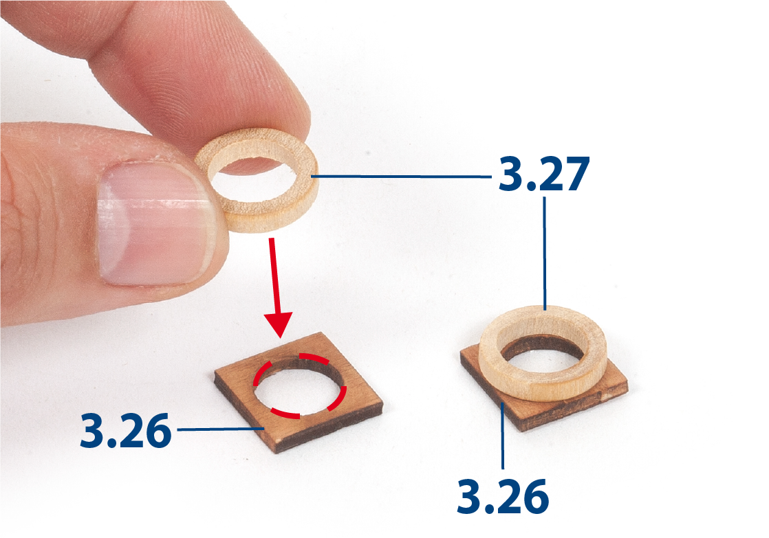
Přilepte kroužek 3.27 (ø10 mm) vycentrovaný na dílu 3.26. Opakujte postup, abyste získali další stejnou sadu.
Můžete ověřit, že máte správný kroužek, když ho vyzkoušíte na stěžeň MT24.
Krok 14
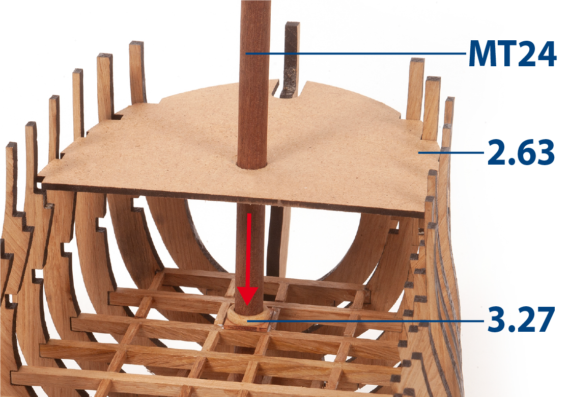
Použijte díly 2.63 a MT24 k zarovnání otvorů ve stěžni. Poté jednu z montáží trvale slepte.
Použijte modelářský nůž k rozšíření otvoru 3.27, pokud je nasazení stožáru příliš těsné.
Krok 15
Postupujte stejným způsobem, abyste zarovnali otvory ve středovém stěžni, použijte díly MT24 a 2.68. Slepte druhou sestavu.
Použijte modelářský nůž k rozšíření otvoru 3.27, pokud je nasazení stožáru příliš těsné.
Krok 16
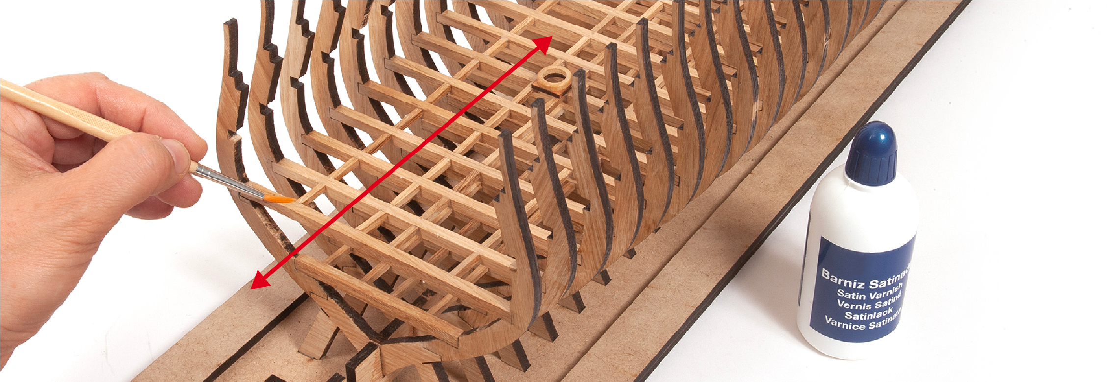
Aplikujte lak na všechny přidané části.
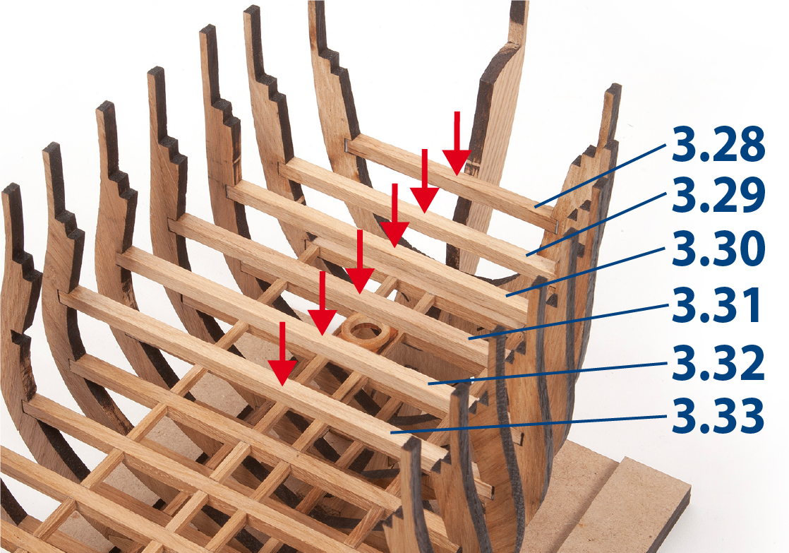
Krok 1
Ustřihněte na délku a slepte díly 3.28 až 3.33 (5 x 5 mm).
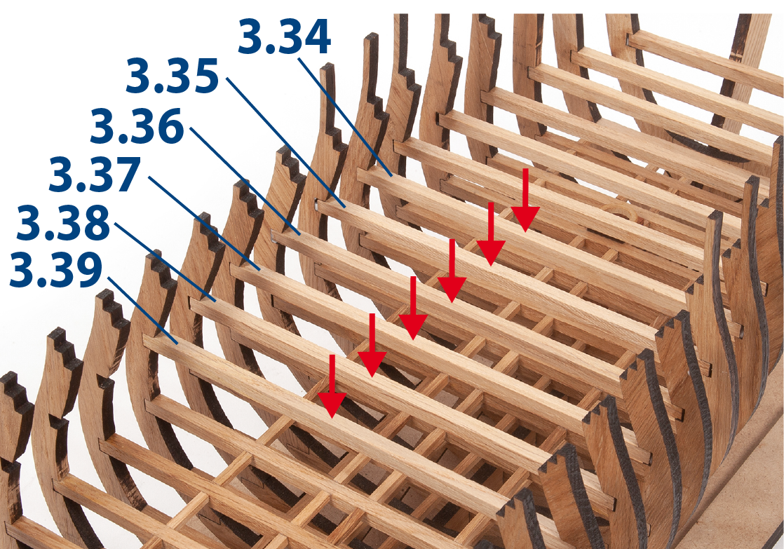
Krok 2
Ustřihněte na délku a slepte díly 3.34 až 3.39 (5 x 5 mm).
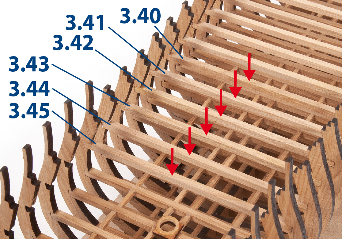
Krok 3
Nastříhejte na délku a slepte díly 3.40 až 3.45 (5 x 5 mm).
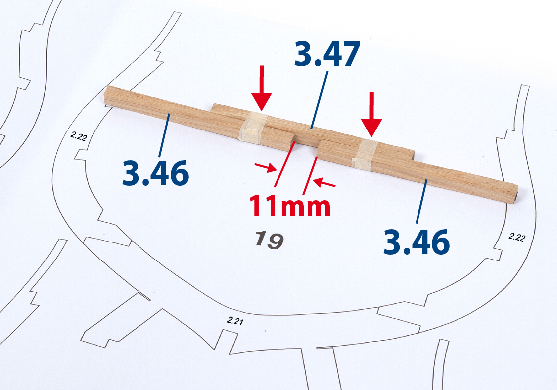
Krok 4
Použijte 5 x 5mm lištu a šablonu pro žebro 19 k oříznutí dvou kusů 3.46 a jednoho kusu 3.47 na velikost. Dočasně spojte tyto kusy dohromady pomocí dvou kusů maskovací pásky.
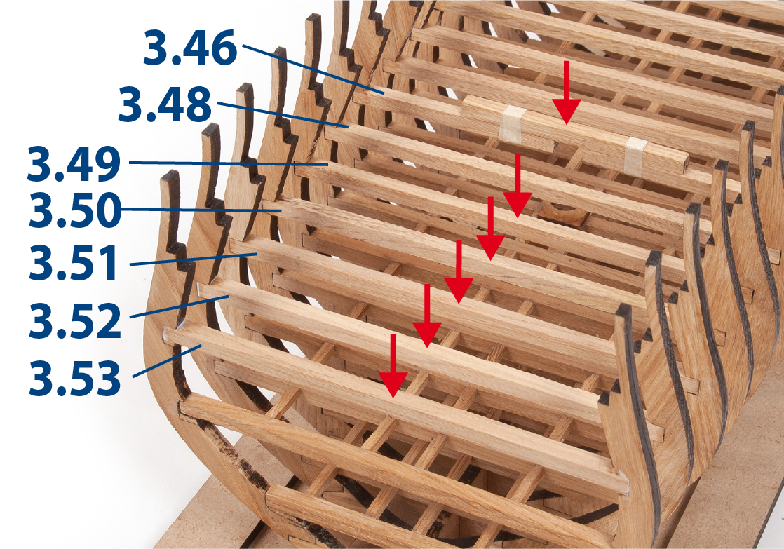
Krok 5
Lepte díly 3.46 až 3.53 (5 x 5mm) do vybrání následujících rámů.
Jakmile lepidlo na 3.46 zaschne, můžete odstranit maskovací pásku a dočasné spojení.
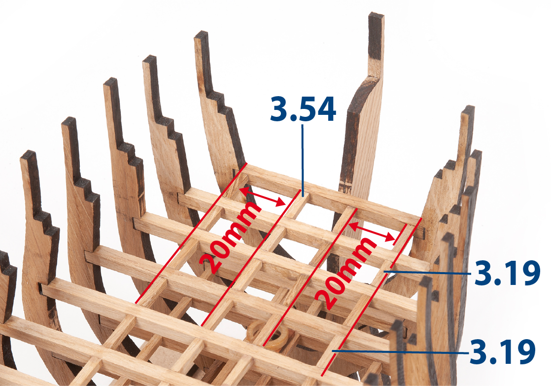
Krok 6
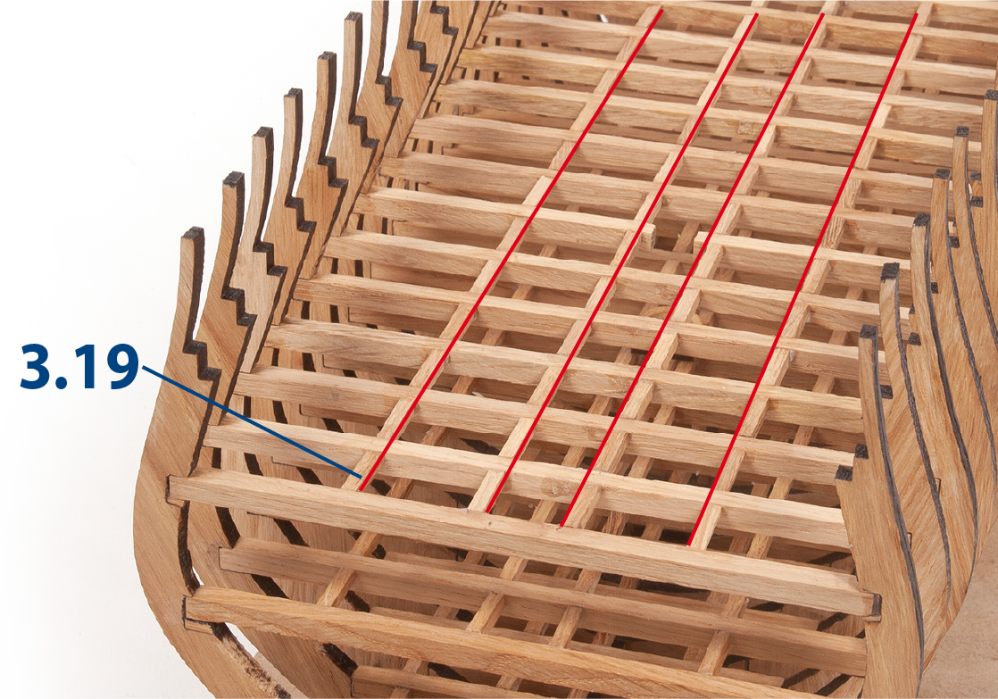
Nastříhejte na velikost čtyři kusy 3.54 (3 x 3 mm) a nalepte je na místo. Poté nastříhejte a nalepte kusy 3.19 po předchozích.
Krok 7
Pokračujte v lepení dílů 3.19 v linii s předchozími.
Krok 8
Celkem 92 částí 3.19 musí být nalepeno.
Krok 9
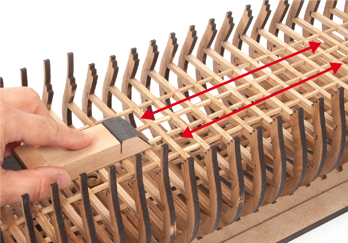
Brousit díly přidané do konstrukce smirkovým papírem s jemným zrnem.
Krok 10
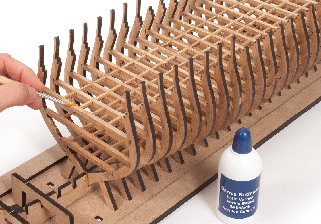
Aplikujte lak na všechny přidané díly, kromě horní plochy dílů v této oblasti konstrukce.
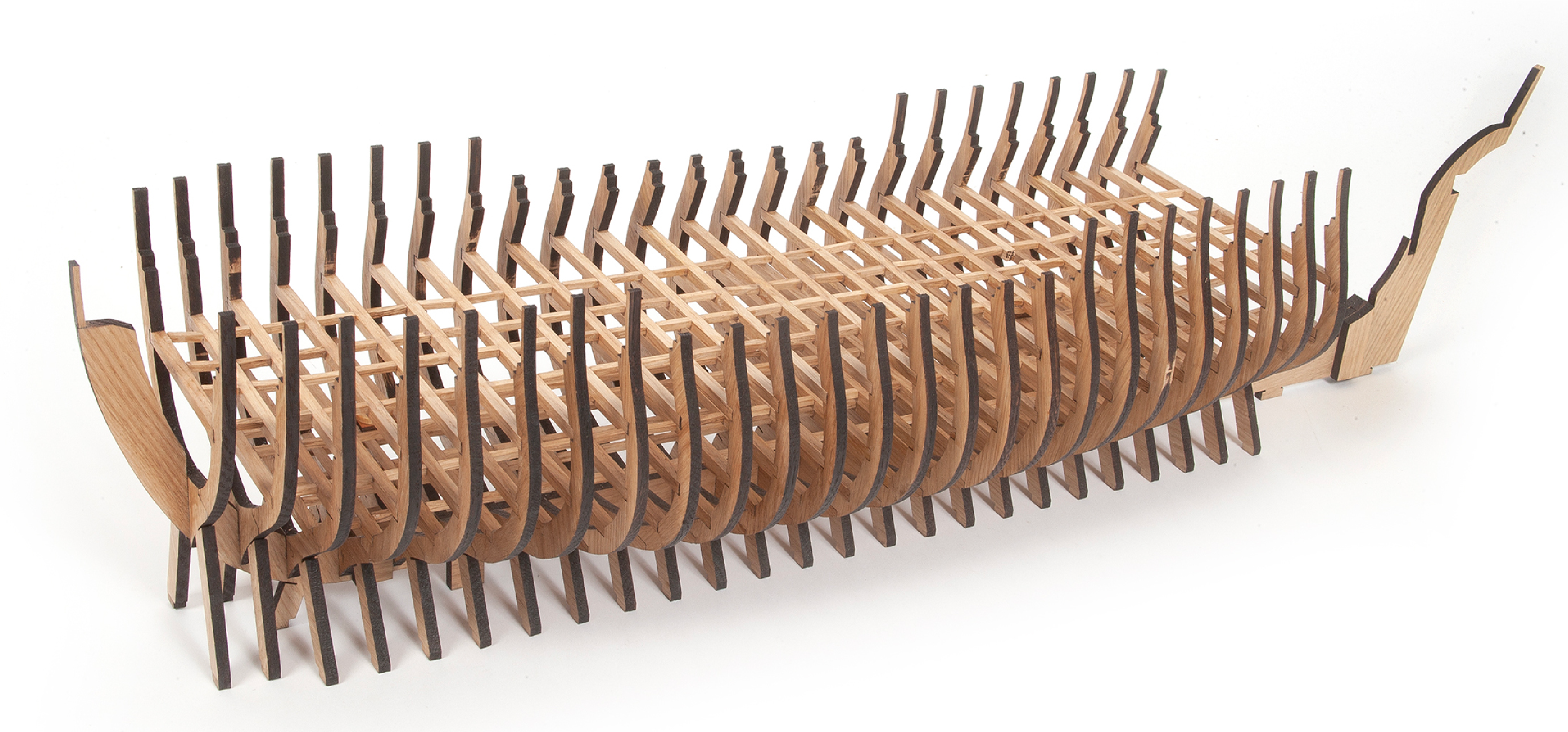
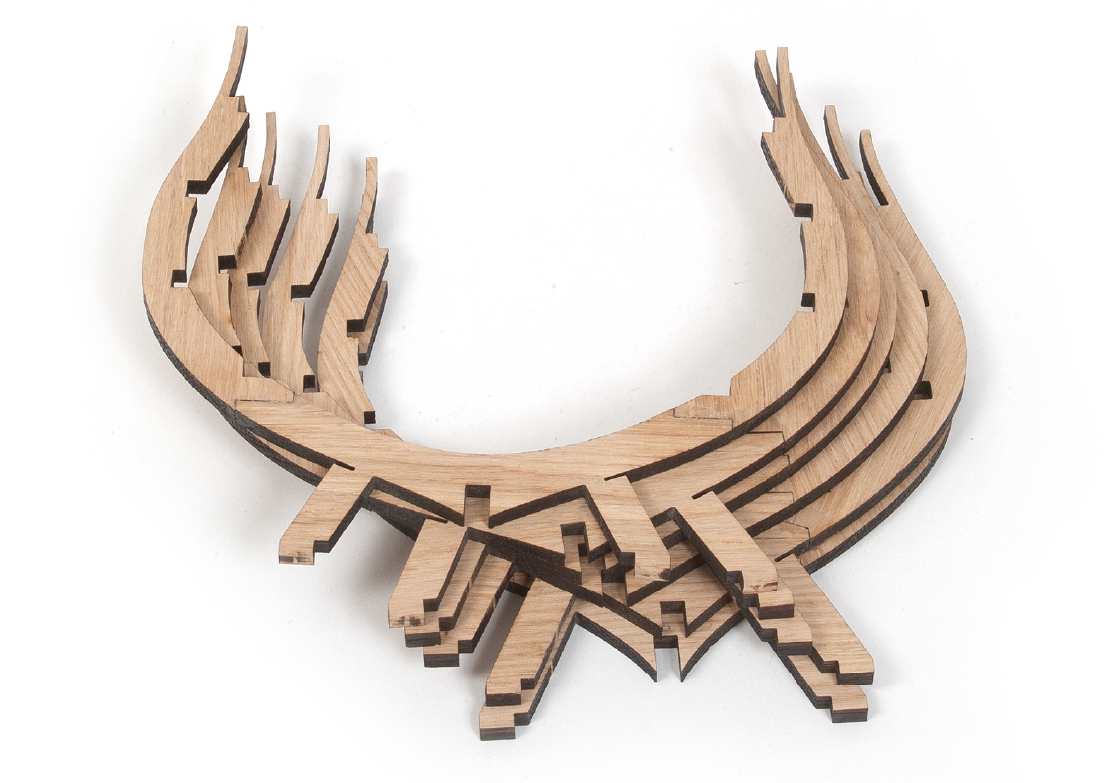
Krok 11
V tomto obrázku vám ukážeme, jak by měla struktura vypadat, jakmile bude V této fázi sestavení dokončena.