Pacco 09
ISTRUZIONI DI MONTAGGIO
Istruzioni per la costruzione della tua nave modello U.S.S. Constitution
Il tuo modello dell'U.S.S. Constitution è diviso in 12 pacchetti.
Dovrai seguire le foto di montaggio passo dopo passo, i piani e i testi esplicativi qui sotto.
Conserva i materiali avanzati di ogni pacchetto per utilizzarli quando ti sarà indicato di farlo in una fase successiva delle istruzioni di montaggio.
I fogli IP mostrati di seguito sono disegni di parti tagliate al laser e parti in ottone fotoinciso e serviranno come guida per l'identificazione di alcune parti.
Utilizza la tabella RIFERIMENTO PARTI per aiutarti a localizzare le parti.
Le sagome PL-00 (stampate in scala 1/1) incluse in ogni pacchetto serviranno come guida per la costruzione delle ordinate.
Controlla l'elenco qui sotto per assicurarti di avere tutti gli strumenti necessari per costruire la tua nave in legno.
Quando rimuovi una parte, taglia le ordinate che uniscono la parte alla piastra di legno con un taglierino.
Rimuovi le parti con attenzione per non romperle.
Conserva e immagazzina le parti nei loro telaietti. Rimuovi solo le parti su cui stai lavorando in ogni step.
Un supporto aggiuntivo può essere trovato sul nostro forum o dalla pagina della Directory degli Esperti del nostro sito web.
ELENCO PARTI
| Materiale | Quantità | |
| Listelli di legno | ||
| 1 x 4 x 100 mm | Legno di tiglio | 14 |
| Altri pezzi | ||
| Filo ø1 x 100 mm | Ottone | 35 |
| Filo ø1,5 x 100 mm | Ottone | 5 |
| Filo ø0,5 x 100 mm | Ottone | 60 |
| Anello ø3 mm | Ottone | 125 |
| Set di longheroni della scala | 7 | |
| Caviglia di ormeggio grande | Ottone | 2 |
| Caviglia di ormeggio piccola | Ottone | 12 |
| Puleggia 4 mm | 150 | |
| Blocco 4 mm | 75 | |
| Anello della boma | Ottone | 1 |
| Anello dell’albero | Ottone | 2 |
| Costole di racage | Ottone | 6 |
| Vetro finestra | Acetato | 2 |
Strumenti di cui avrai bisogno: tappetino da taglio, matita, taglierino, carta abrasiva a grana fine o spugna abrasiva, lima, colla vinilica, colla super (colla cianoacrilata), nastro da mascheratura, squadra, seghetto per metallo, blocchetto abrasivo, righello in acciaio da 30 cm, morsetti, strumenti di incisione
RIFERIMENTO PARTI
NUMERO DI PARTE | POSIZIONE IP-SHEET | NUMERO DI PARTE | POSIZIONE IP-SHEET | NUMERO DI PARTE | POSIZIONE IP-SHEET |
| 9.5 | 2001-22 | 9.24 | 2001-23 | 9.30 | 2001-23 |
| 9.6 | 2001-22 | 9.25 | 2001-23 | 9.31 | 2001-23 |
| 9.9 | 2001-22 | 9.26 | 2001-23 | 9.39 | 2001-29 |
| 9.10 | 2001-22 | 9.27 | 2001-23 | 9.46 | 2001-32 |
| 9.11 | 2001-22 | 9.28 | 2001-23 | 9.47 | 2001-32 |
| 9.22 | 2001-23 | 9.29 | 2001-23 | 9.50 | 2001-33 |
| 9.23 | 2001-23 | 9.30 | 2001-23 | 9.51 | 2001-32 |
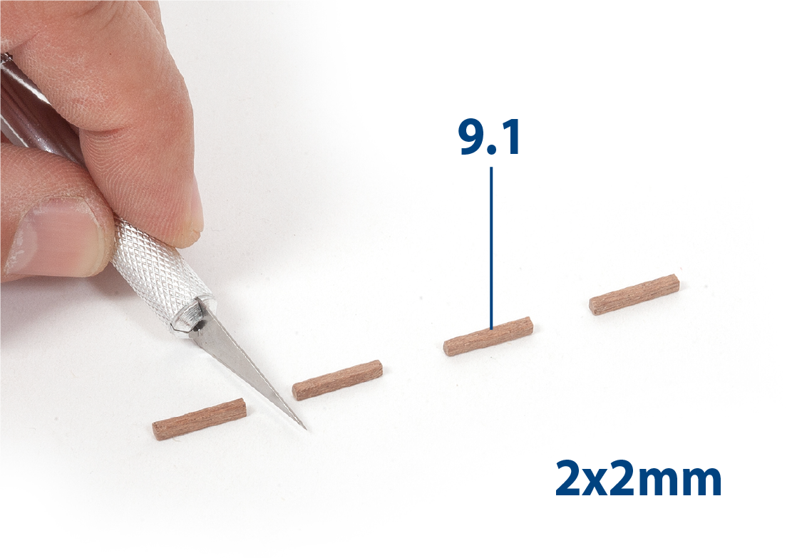
Passo 1
Taglia otto pezzi 9.1 (2 × 2 × 136 mm, mogano) alla lunghezza richiesta e carteggiali.
Passo 2
Incolla i pezzi 9.1 sulla parte 9.2 (cabestano, pacco 08) come mostrato.
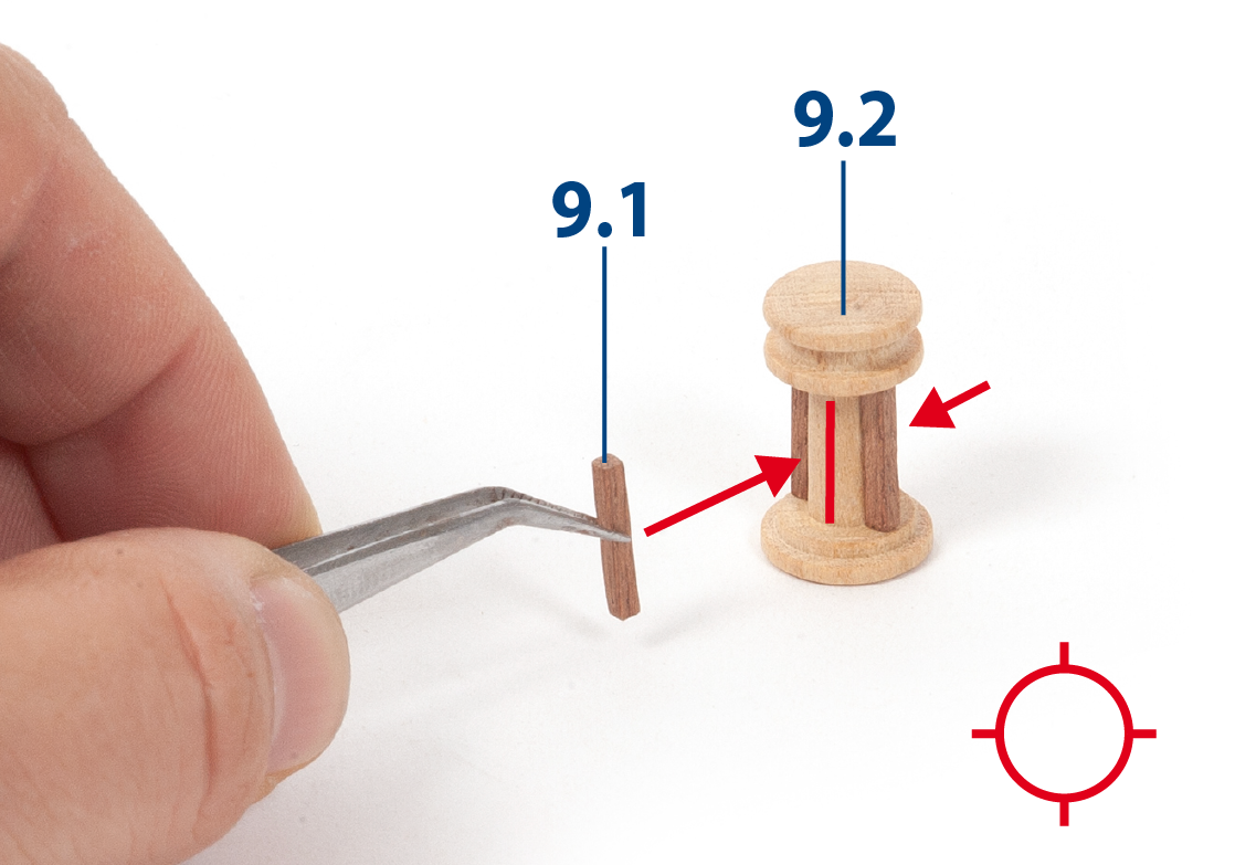
Passo 3
Continua a incollare i pezzi 9.1 all'assemblaggio come mostrato.
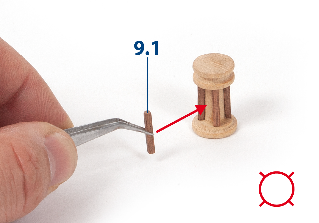
Passo 4
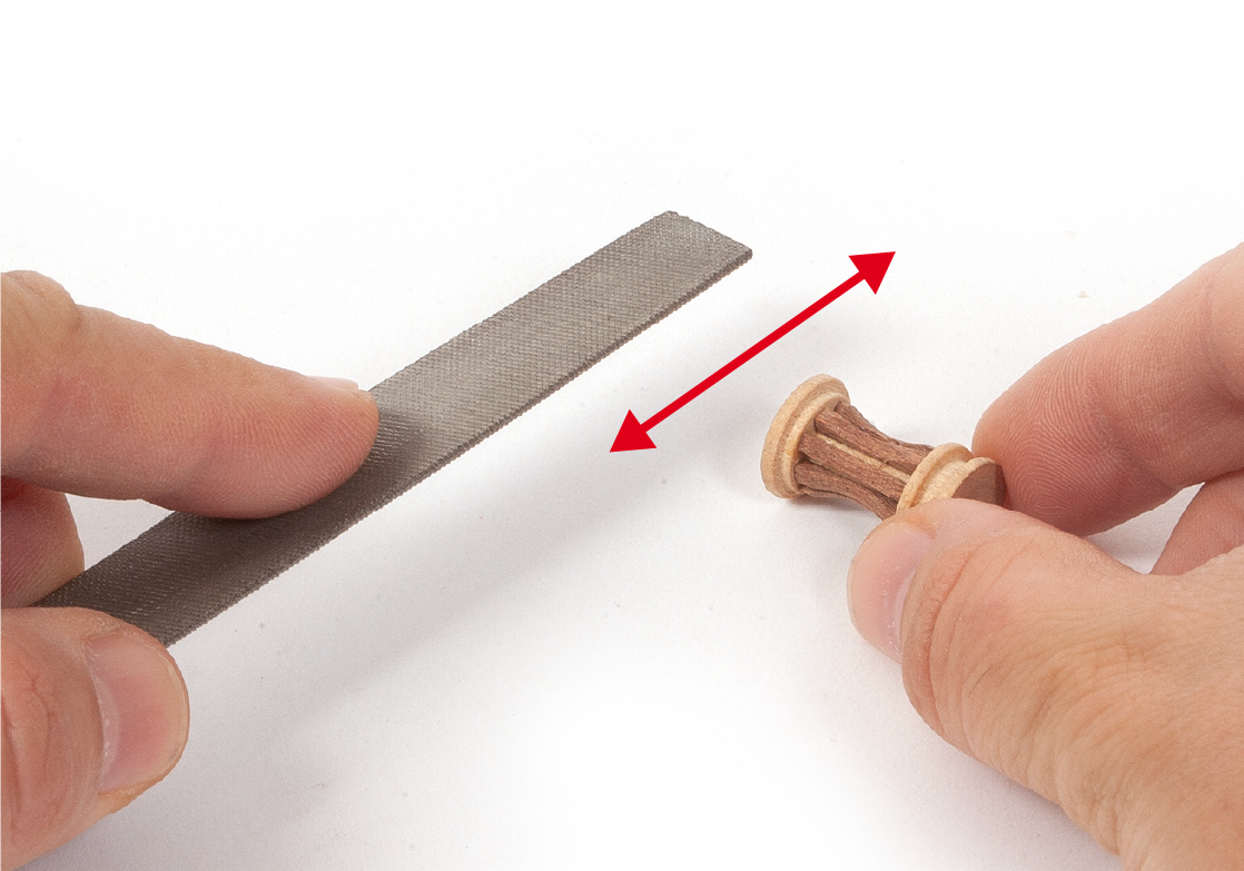
Utilizza una lima arrotondata per limare leggermente la parte centrale dei piezzi 9.1, in modo da ottenere la forma desiderata.
Passo 5
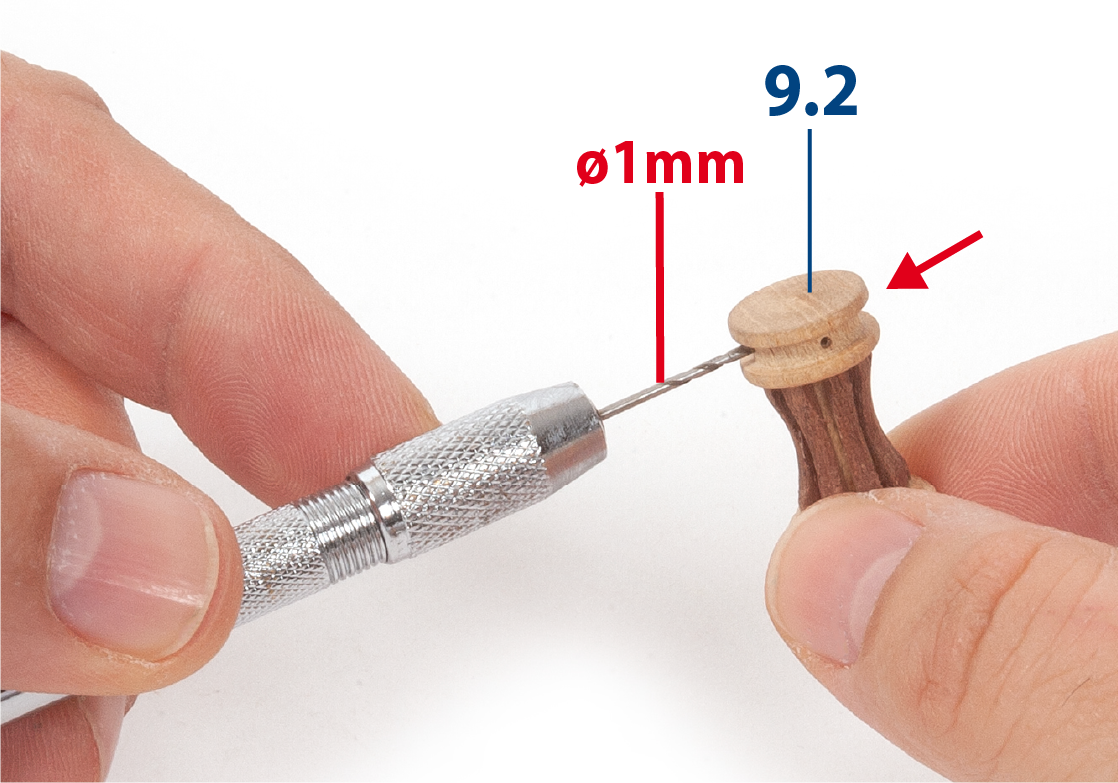
Fora otto fori (ø1 mm) nella parte 9.2 come mostrato nella foto (vedi passo 8).
Passo 6
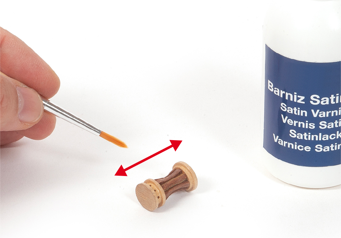
Vernicia l’assemblaggio.
Passo 7
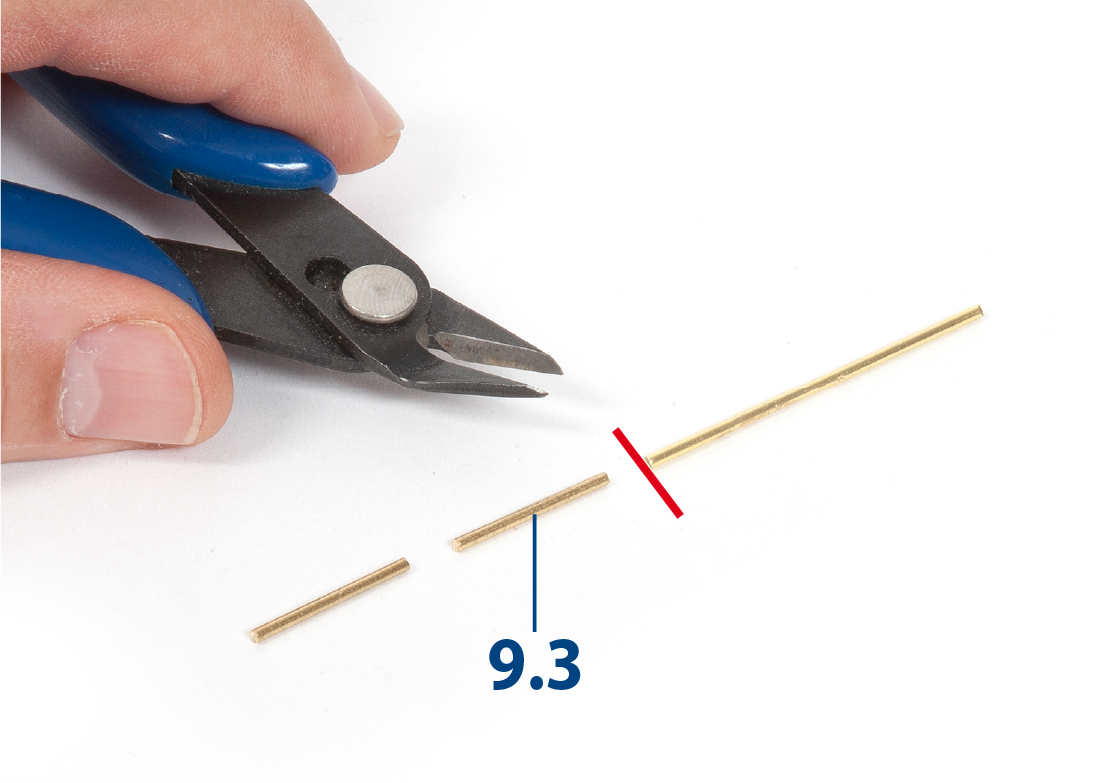
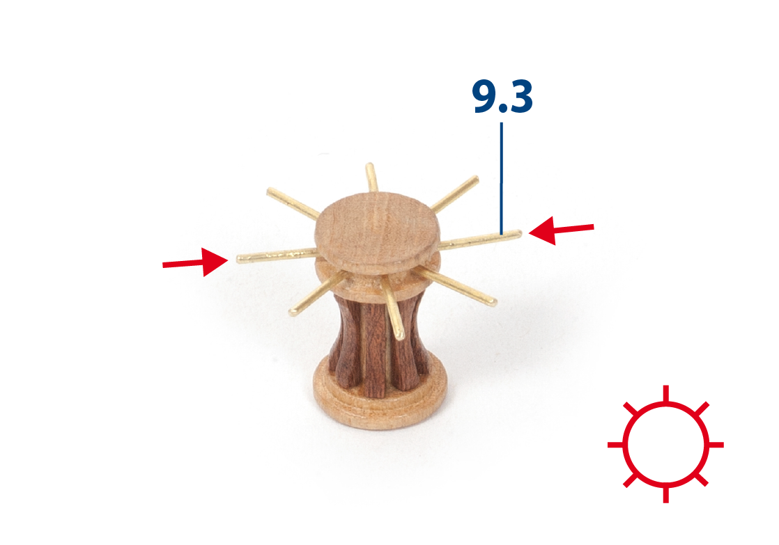
Taglia otto pezzi 9.3 alla lunghezza richiesta (ø1 x 10 mm).
Passo 8
Inserisci e incolla le parti 9.3 come mostrato nella foto.
Passo 9
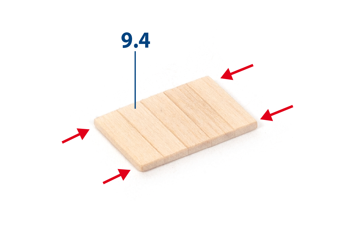
Taglia i pezzi 9.4 (2 x 5 x 17 mm di legno di tiglio) alla lunghezza richiesta e incollali tra loro come mostrato.
Passo 10
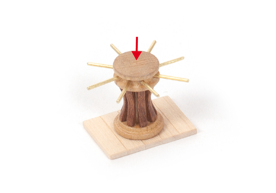
Incolla la parte 9.2 al centro dell’assemblaggio 9.4. Vernicia i pezzi 9.4, poi mettili da parte.
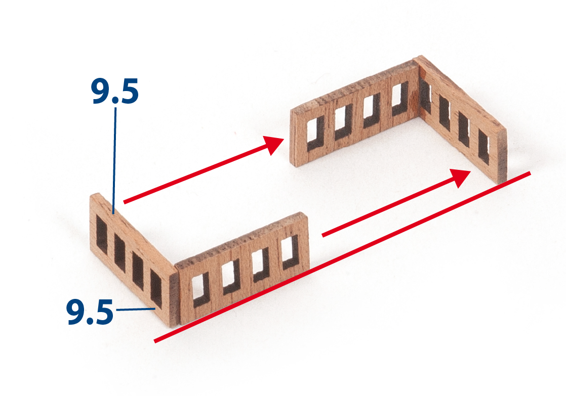
Passo 11
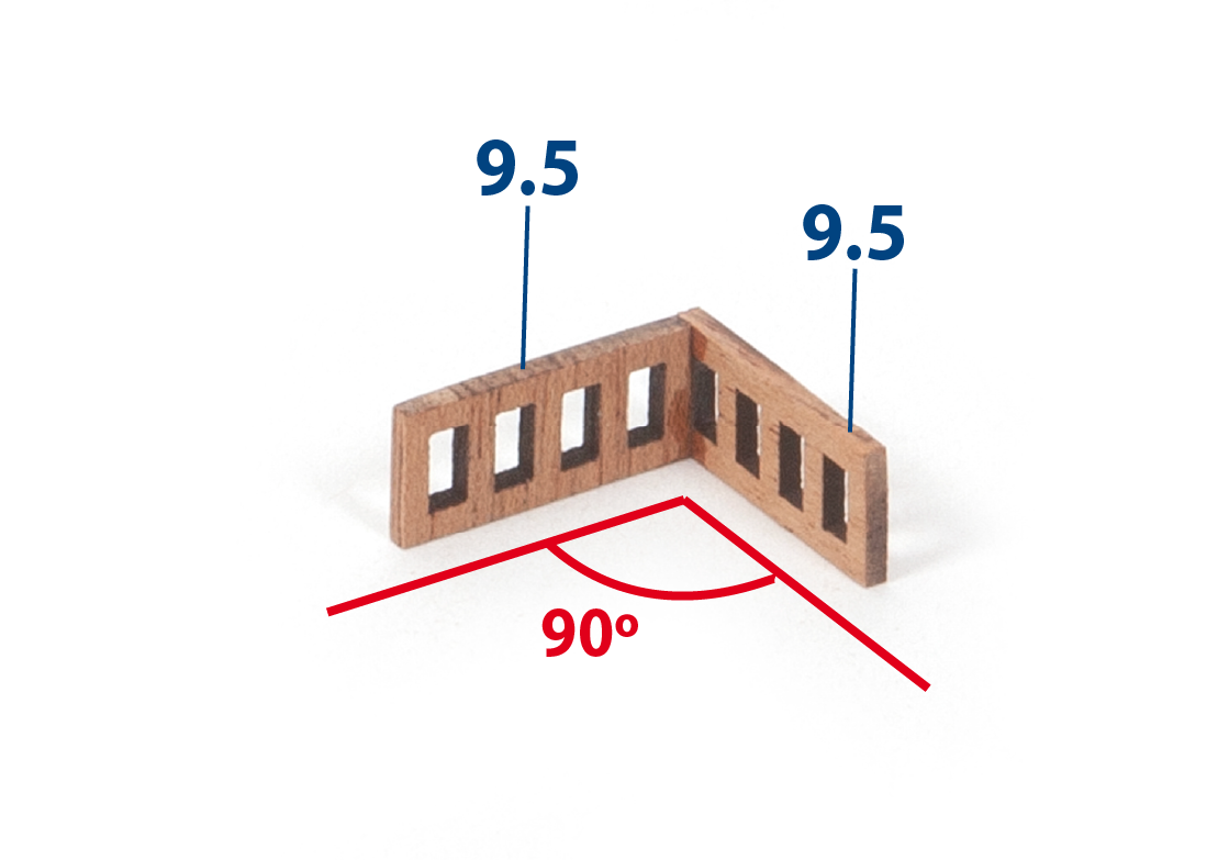
Incolla le parti 9.5 tra loro.
Passo 12
Incolla le altre due parti 9.5 tra loro, poi incollale sul primo assemblaggio, come mostrato.
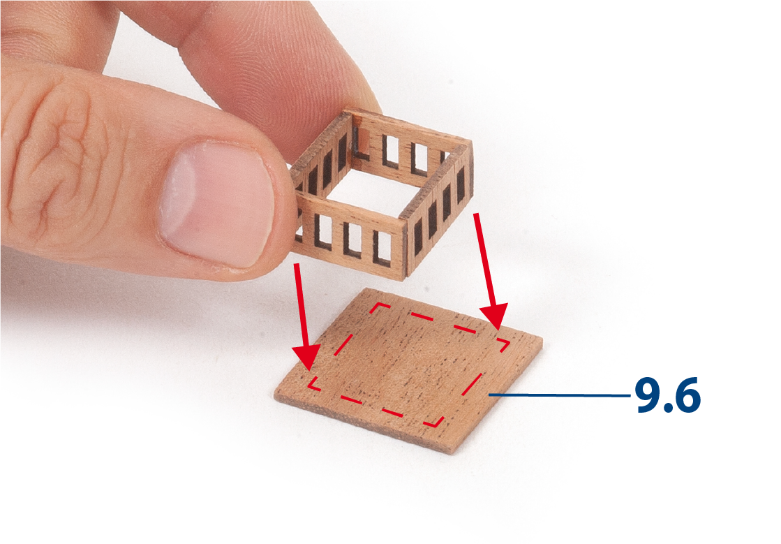
Passo 13
Incolla l’assemblaggio al centro della parte 9.6.
Passo 14
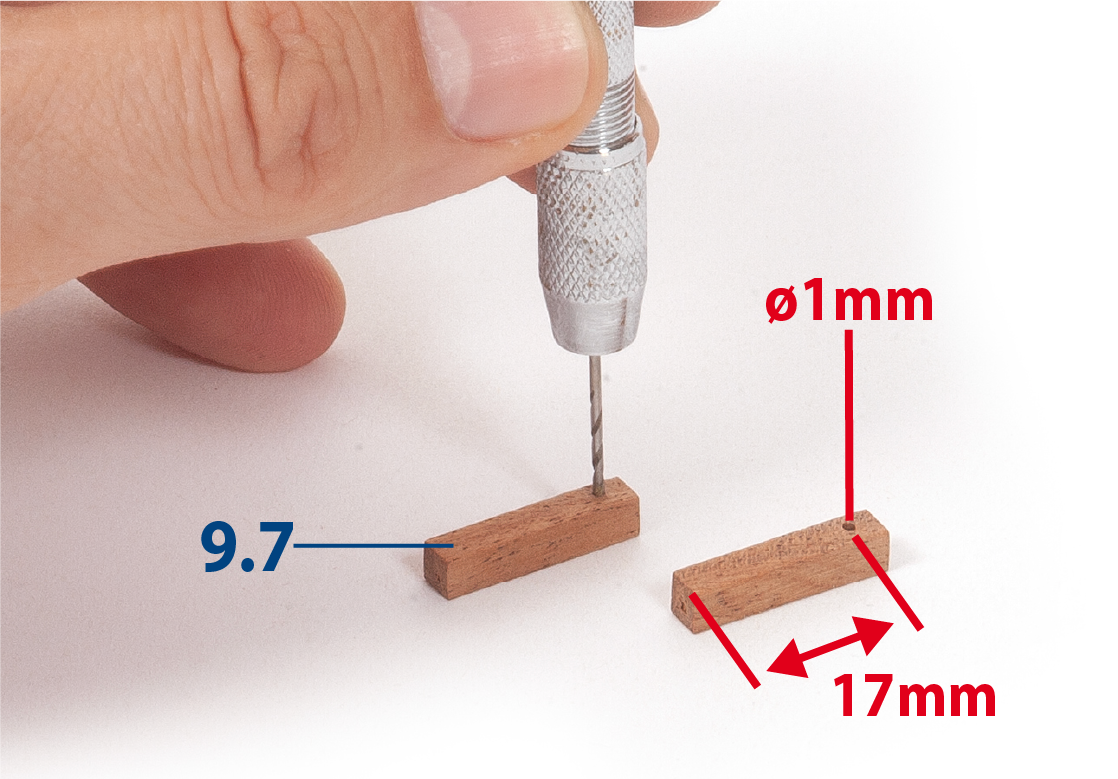
Taglia quattro pezzi 9.7 (4 × 4 × 20 mm di mogano) alla lunghezza necessaria e fora un foro in ciascuno, come mostrato nella foto.
Passo 15
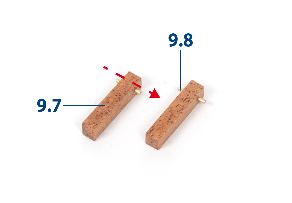
Taglia i pezzi 9.8 (ø1 x 8 mm) alla lunghezza richiesta e inseriscili.
Passo 16
Incolla le parti 9.9 e 9.10 tra loro.
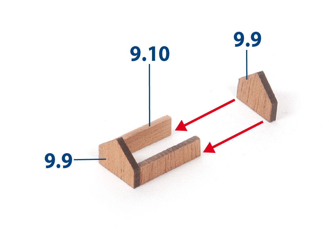
Passo 17
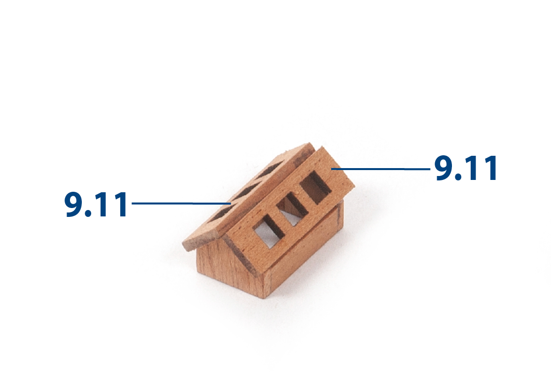
Incolla le parti 9.11 come mostrato per completare l'assemblaggio.
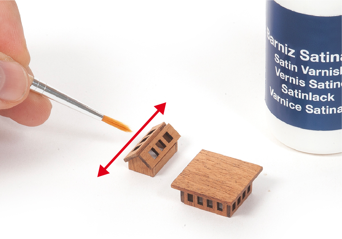
Passo 18
Applicare vernice alle due strutture mostrate nell'immagine.
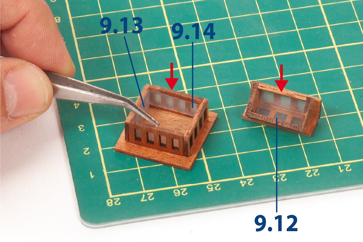
Passo 1
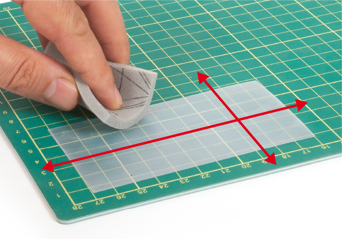
Prendi uno dei fogli di acetato e carteggia uno dei suoi lati usando carta abrasiva o simile.
Passo 2
Ritaglia le parti 9.12, 9.13 e 9.14 (due per ciascun tipo).
Queste parti rappresentano i vetri. Incolla le parti all’interno dei due assemblaggi come mostrato.
| 9.12: 5 x 15 mm |
| 9.13: 8 x 14 mm |
| 9.14: 8 x 17 mm |
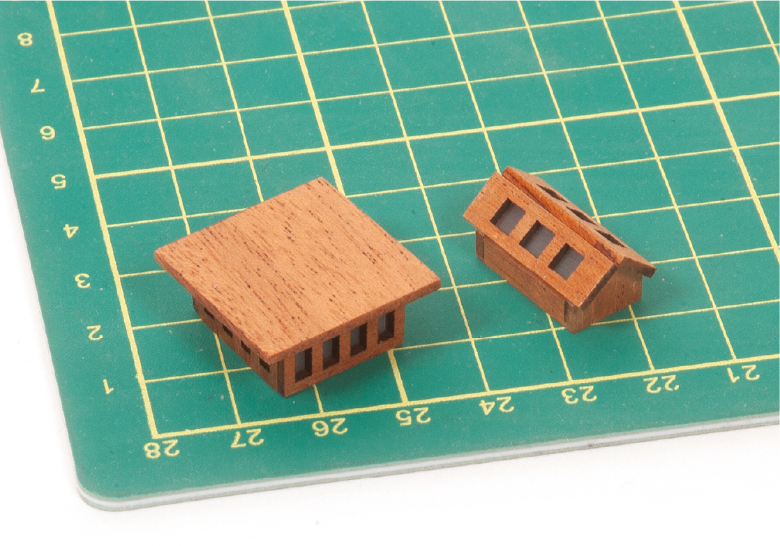
Passo 3
Questa foto mostra gli assemblaggi con l’acetato incollato al loro posto.
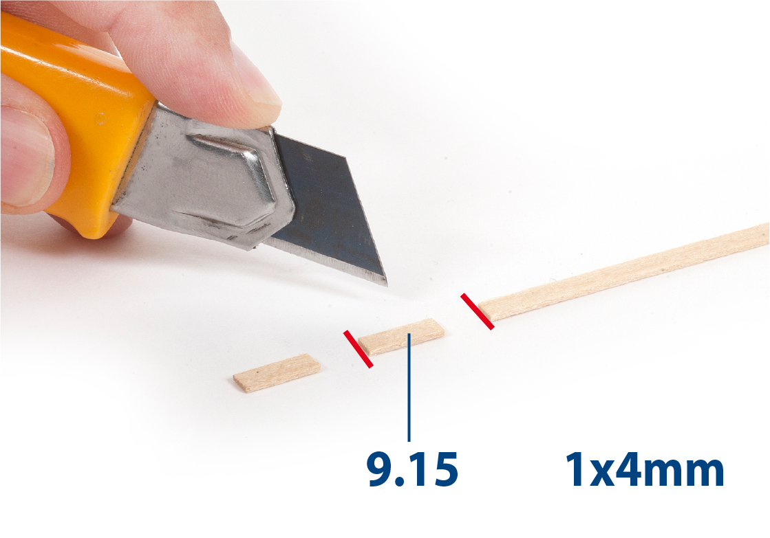
Passo 4
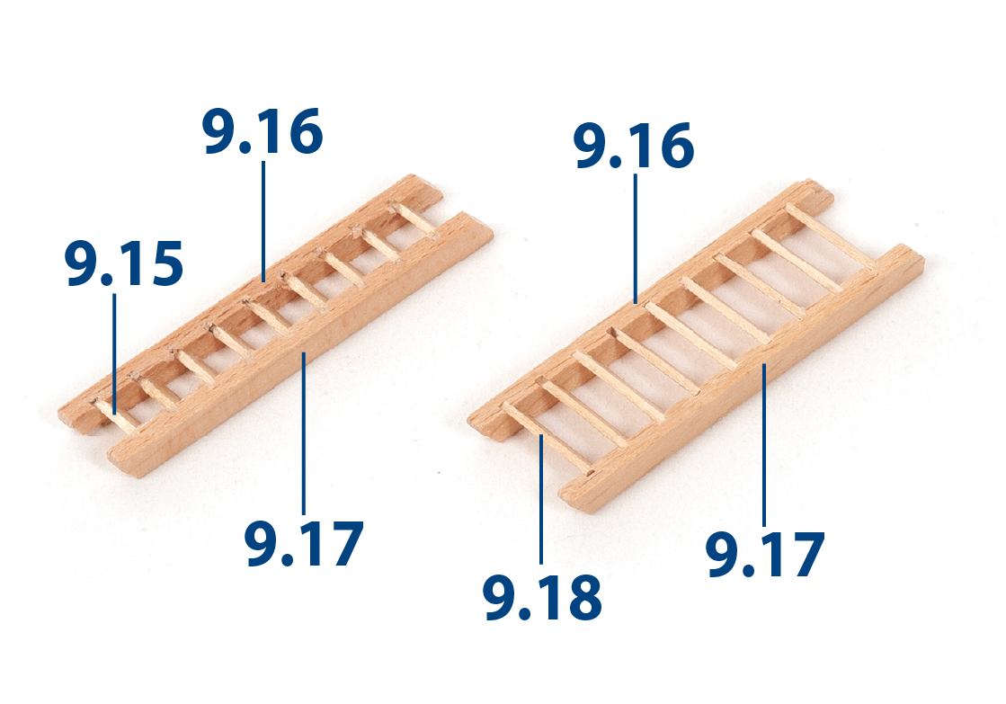
Taglia diciotto pezzi 9.15 (1 x 4 x 7 mm di legno di tiglio) alla lunghezza richiesta.
Passo 5
Incolla i pezzi 9.15 sulla parte 9.16 (montante della scala).
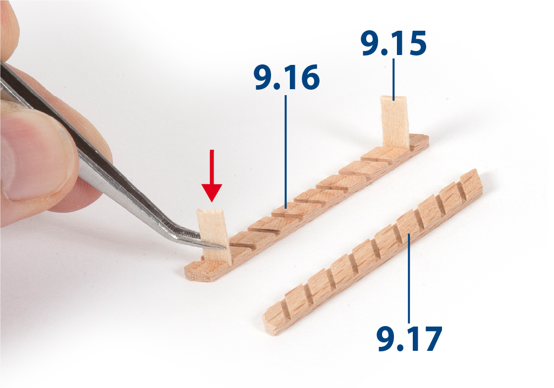
Passo 6
Incolla la parte 9.17 per completare la scala. Ripeti questo processo per costruire una seconda scala.
Costruisci cinque scale larghe utilizzando le parti 9.16, 9.17 e 9.18 (1 x 4 x 12 mm) nello stesso modo. Una volta completate, vernicia tutte le scale.
Passo 7
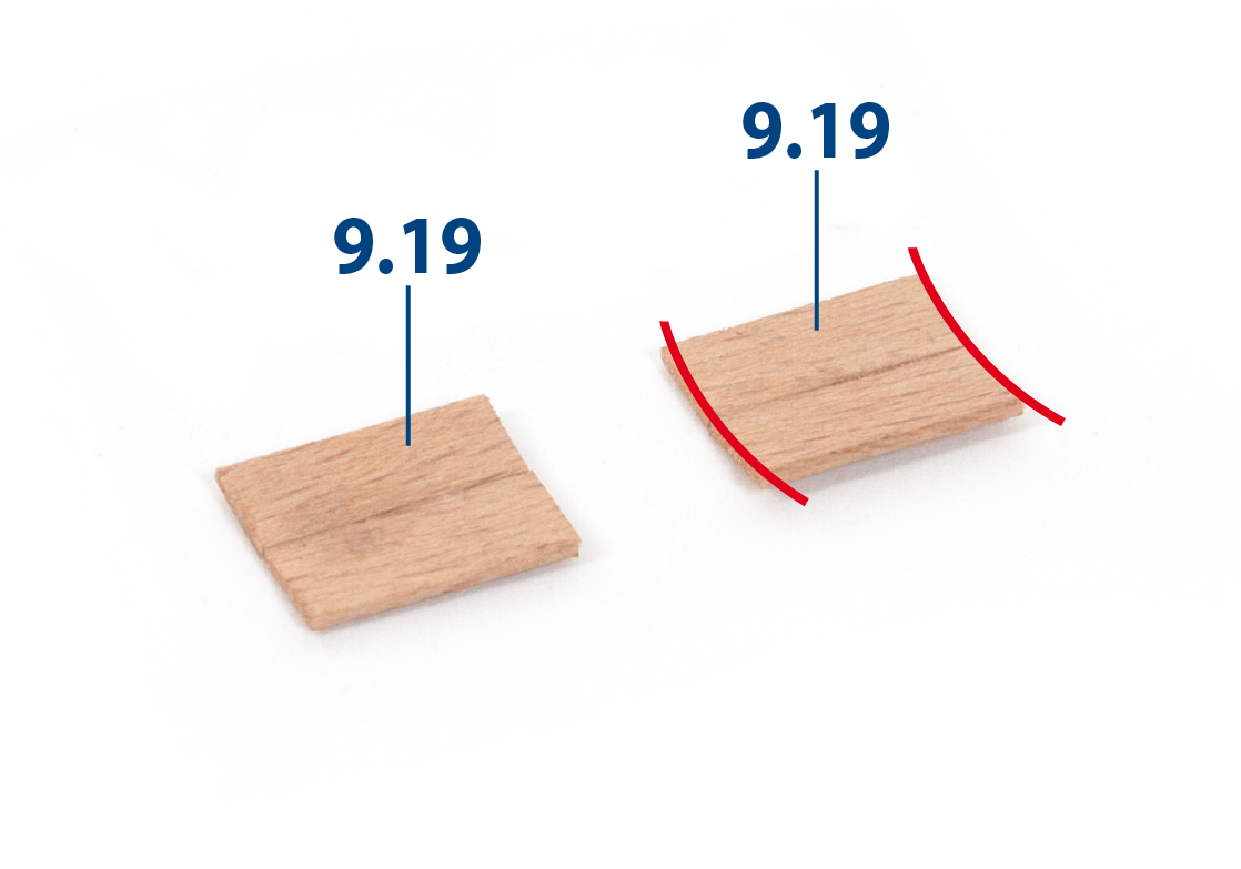
Taglia quattro pezzi 9.19 (1 x 5 x 12 mm), poi incollali tra loro per formare una curva come mostrato.
Passo 8
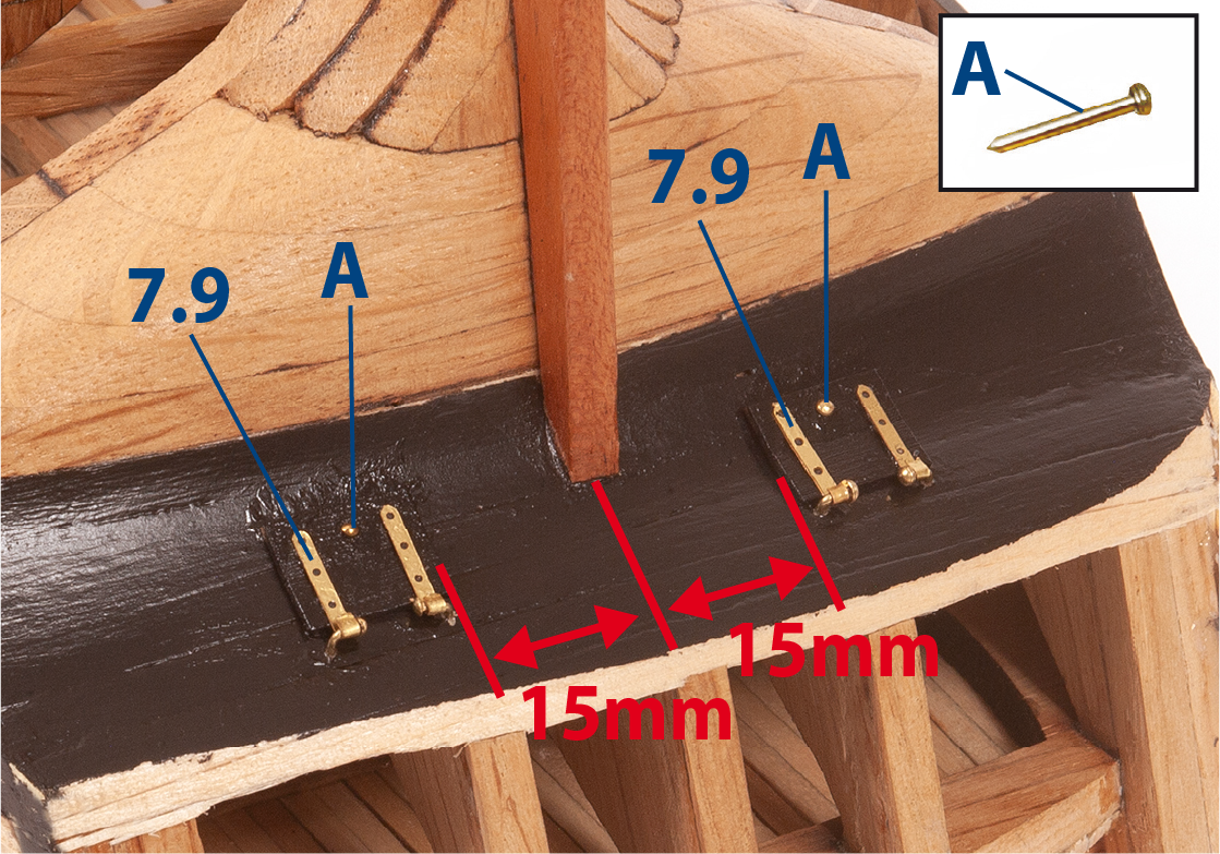
Dipingi di nero i pezzi curvi, poi incolla le cerniere 7.9 come mostrato e fissale con i chiodi (A)
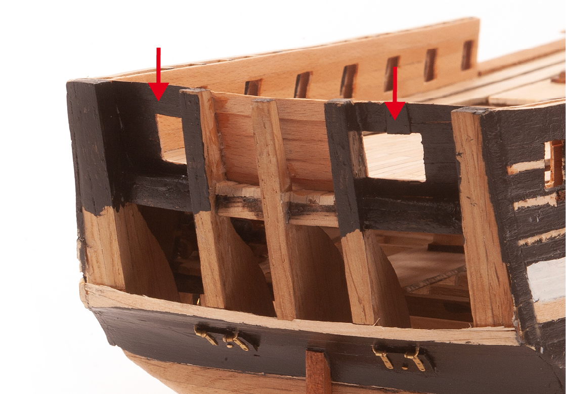
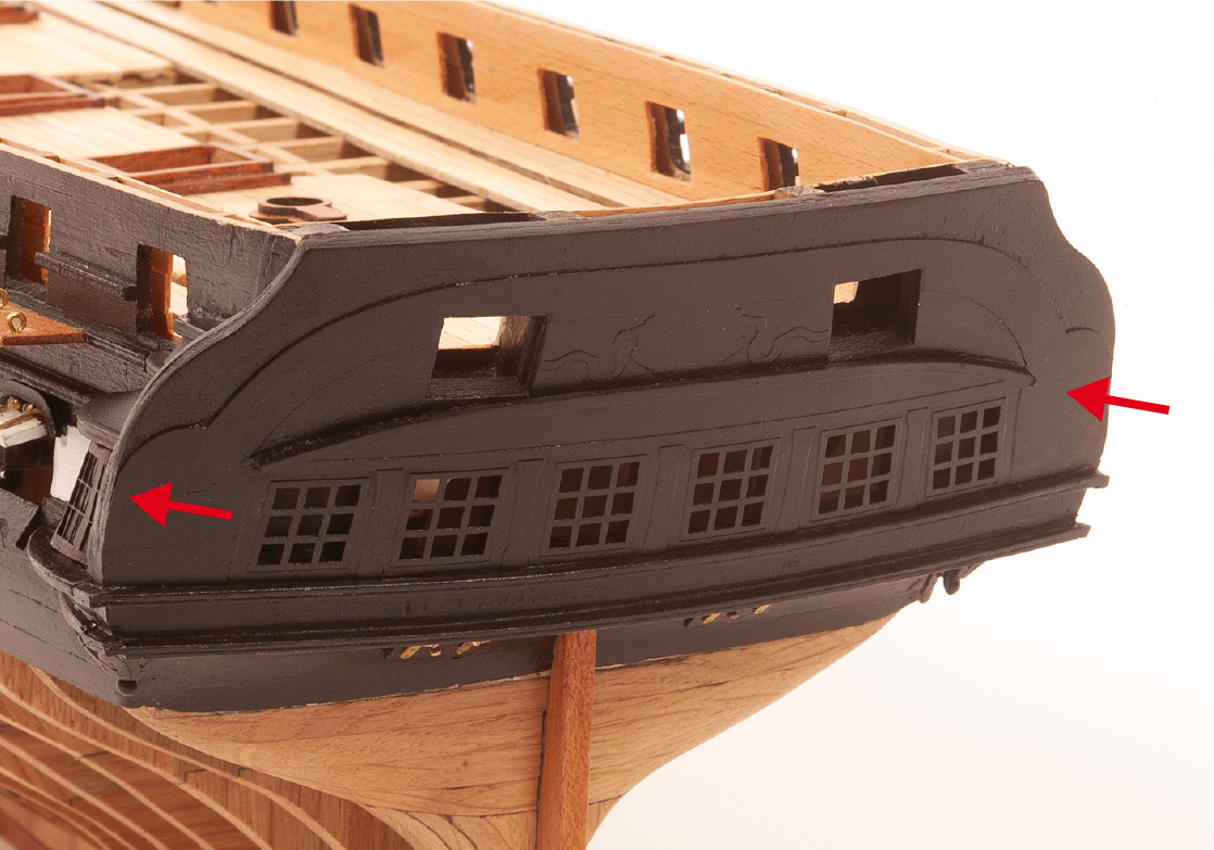
Passo 9
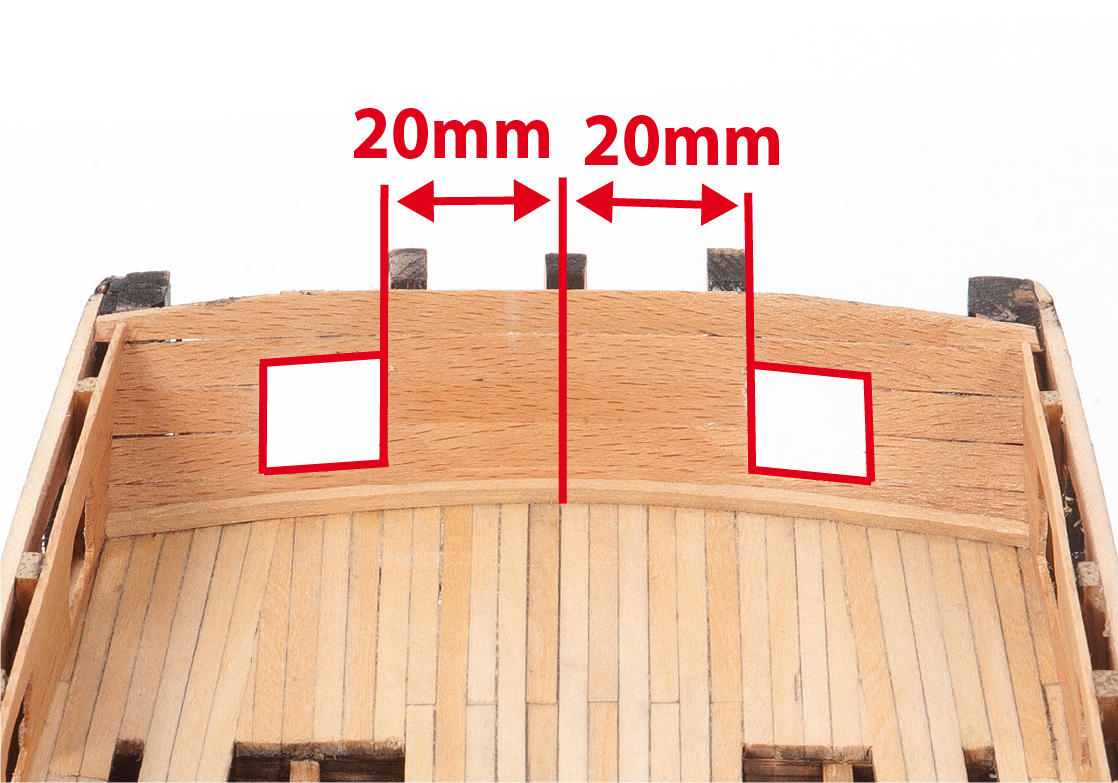
Fora e taglia le aperture mostrate nella foto. Puoi posizionare lo specchio di poppa per individuare i punti da forare (vedi fase 51 passo 3).
Passo 10
Vernicia l'esterno dello scafo di nero come mostrato.
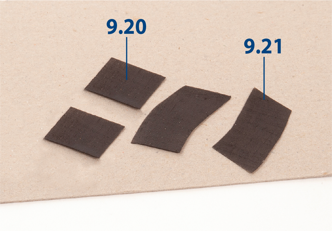
Passo 11
Ritaglia le parti 9.20 e 9.21 dall’acetato. Liscia le parti e poi dipingi un lato di nero.
| 9.20: 17 x 17 mm |
| 9.21: 20 x 40 mm |
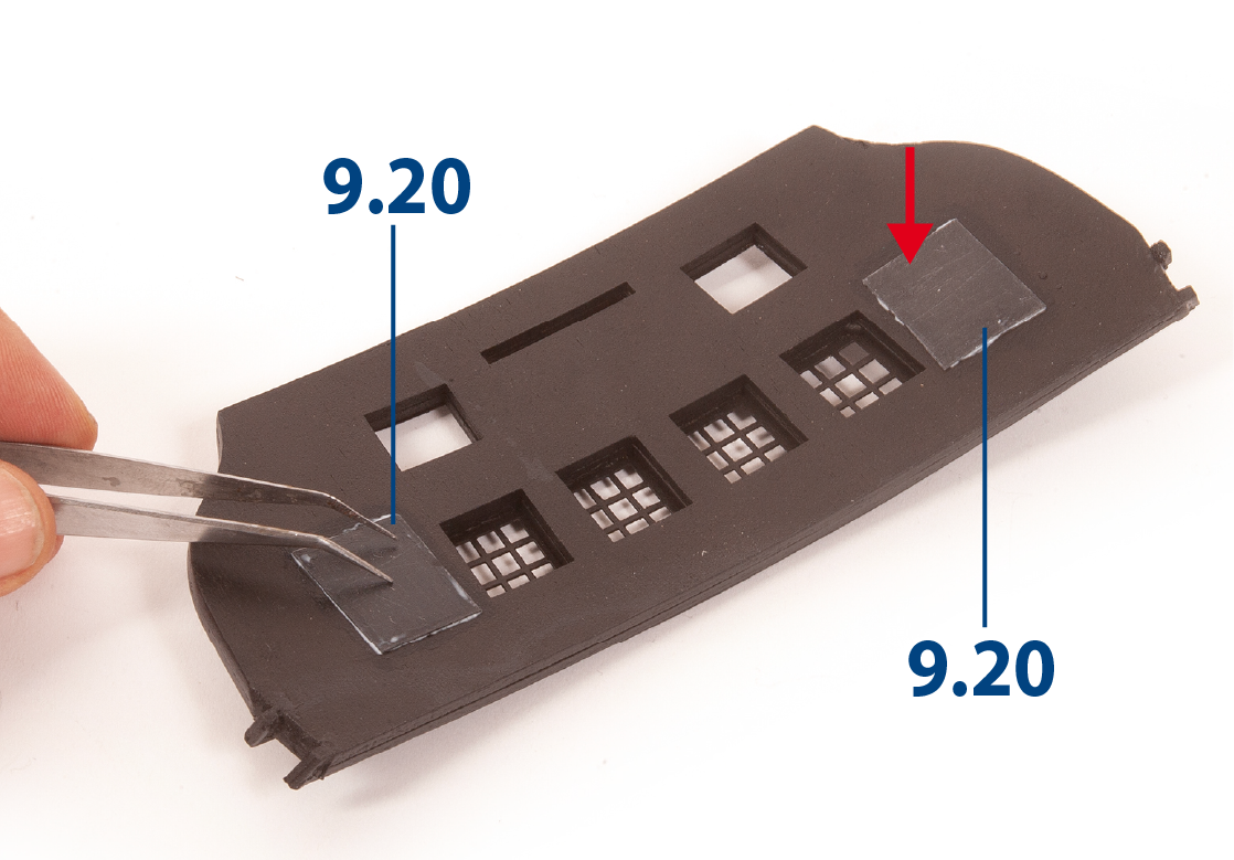
Passo 12
Incolla le parti 9.20 sulle finestre a ciascuna estremità dello specchio di poppa.
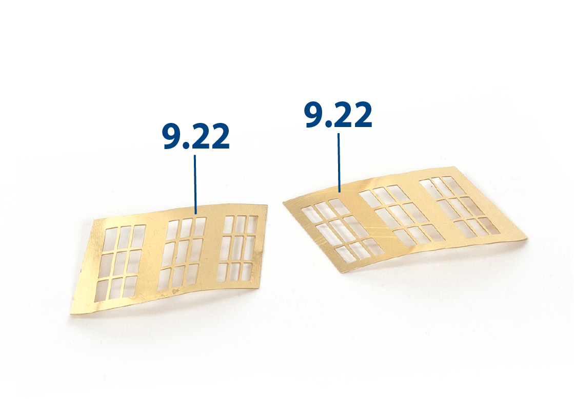
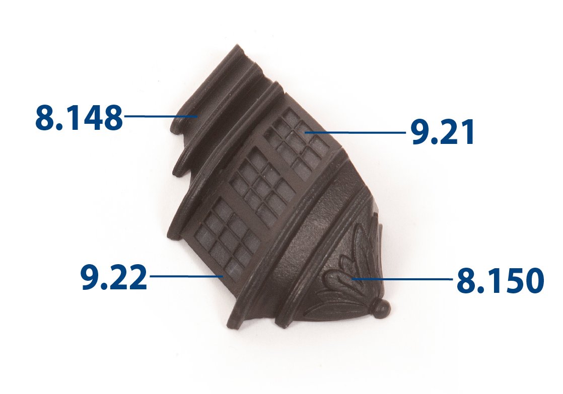
Passo 1
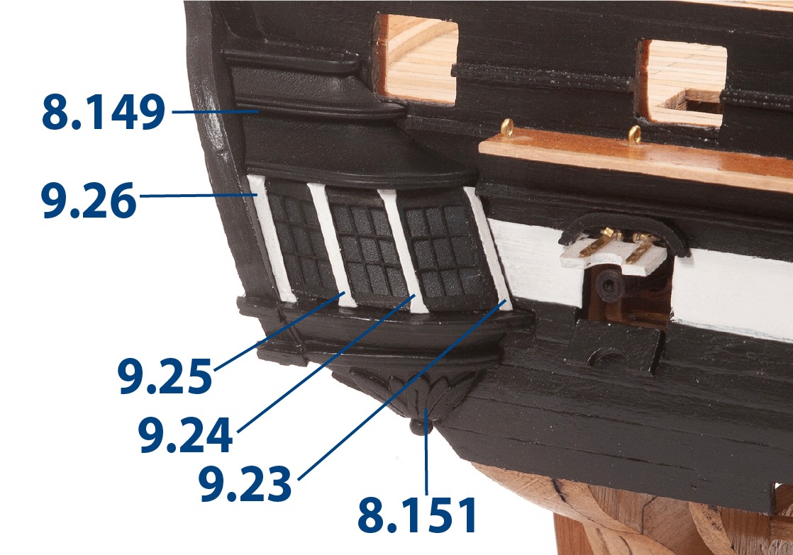
Dai una forma curva alle parti 9.22 affinché seguano il profilo degli ornamenti come mostrato nelle foto qui sotto, poi dipingile di nero.
Passo 2
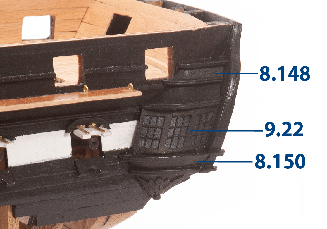
Incolla la parte 9.21 sul retro delle finestre 9.22. Incolla le parti 8.148 (corona della galleria di sinistra) e 8.150 (base della galleria di sinistra) sulla parte 9.22, come mostrato nella foto.
Passo 3
Incolla lo specchio di poppa allo scafo.
Passo 4
Verifica l’adattamento del coronamento e della base della galleria sullo specchio di poppa, poi incollali su uno dei lati dello scafo come indicato.
Passo 5
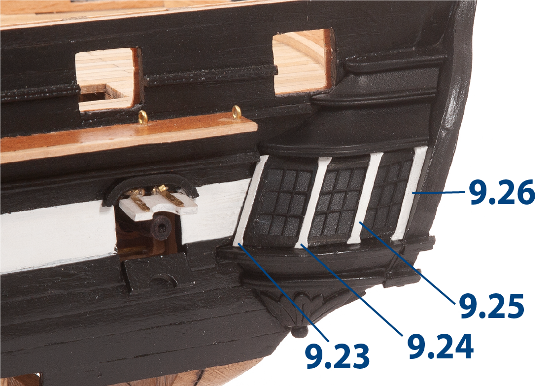
Regola le colonne da 9.23 a 9.26 affinché si adattino, dipingile di bianco, poi incollale in posizione come mostrato.
Passo 6
Ripeti i passi da 1 a 5 per adattare le finestre sul lato opposto dello scafo. Puoi utilizzare pezzi di listelli dipinti di nero per riempire eventuali spazi, se necessario.
Passo 7
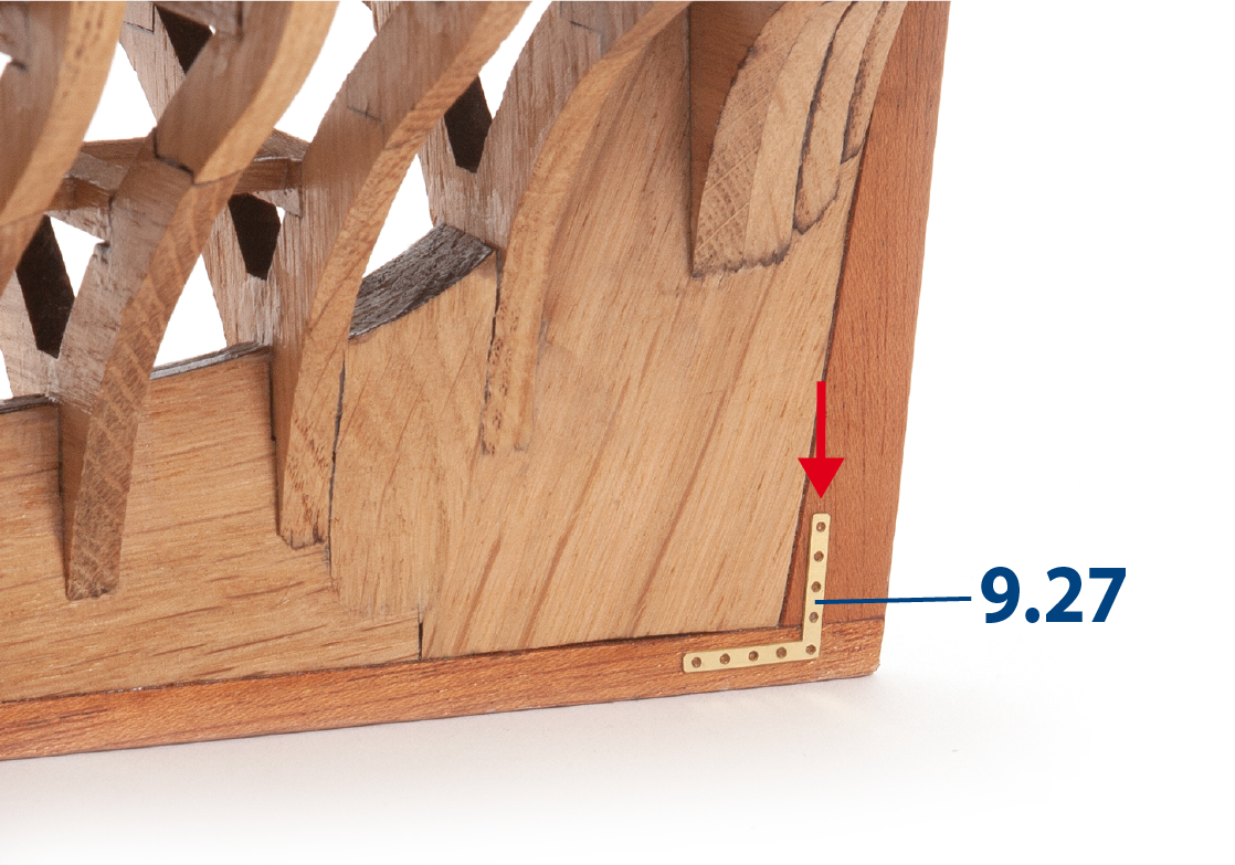
Incolla le parti 9.27 su entrambi i lati del dritto di prua dello scafo.
Passo 8
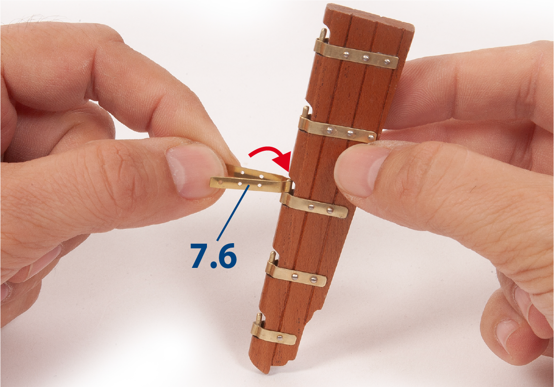
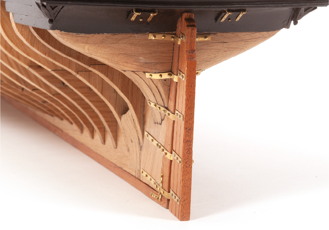
Recupera la pala del timone che hai assemblato nel pacco 07. Monta le cerniere 7.6 sui perni.
Passo 9
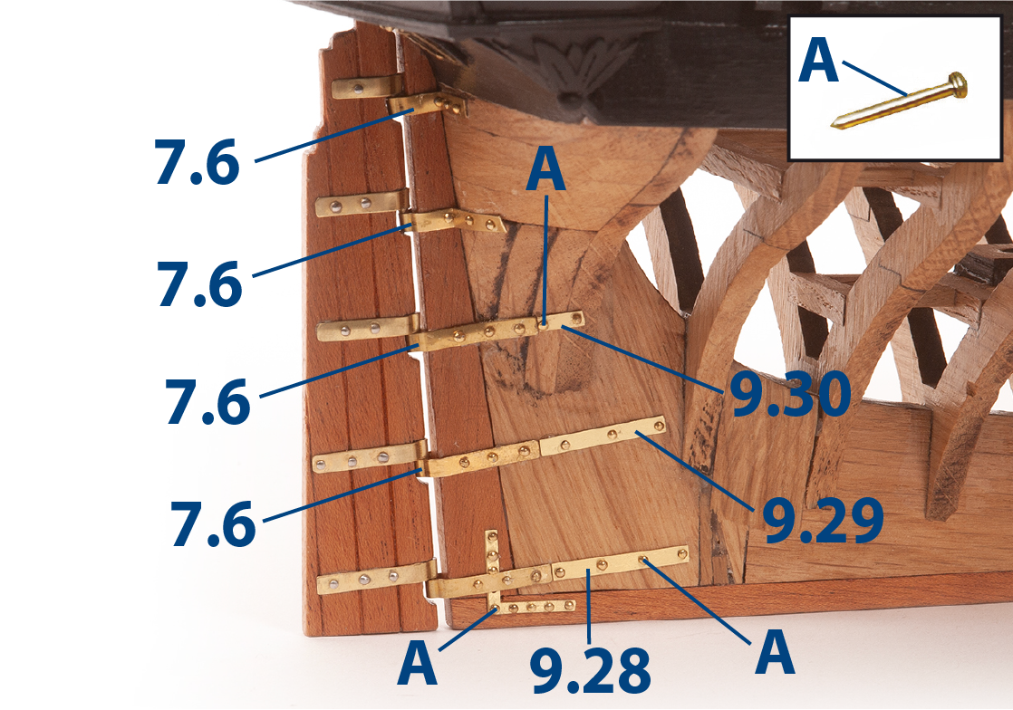
Regola e fissa la pala del timone allo scafo usando i chiodi (A). Dovrai modellare e adattare le parti sul modello. Poi incolla le parti 9.28, 9.29 e 9.30 per garantire la continuità delle cerniere, prima di fissarle con i chiodi (A).
Passo 10
Questa foto mostra le cerniere nella parte superiore dell'assemblaggio da un'altra angolazione.
Passo 11
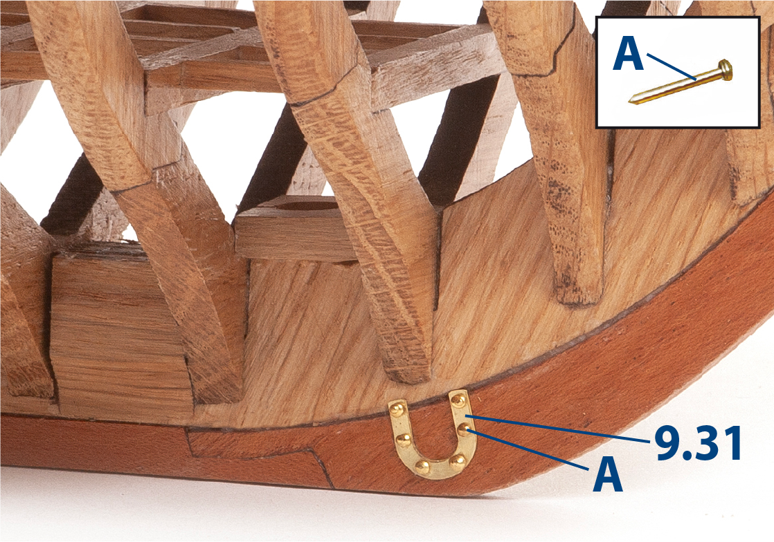
Incolla le parti 9.31 su entrambi i lati dell'assemblaggio come mostrato.
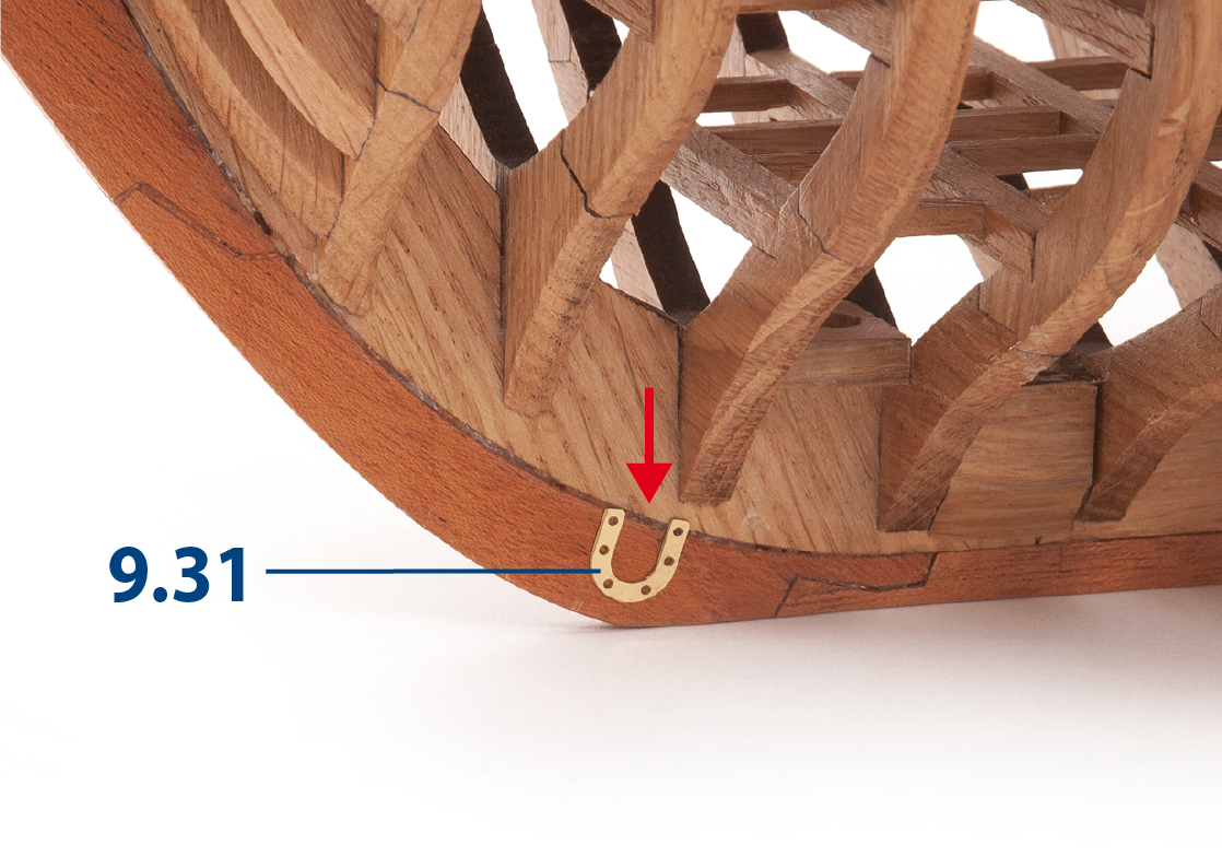
Passo 12
Fissa le due parti 9.31 con i chiodi (A).
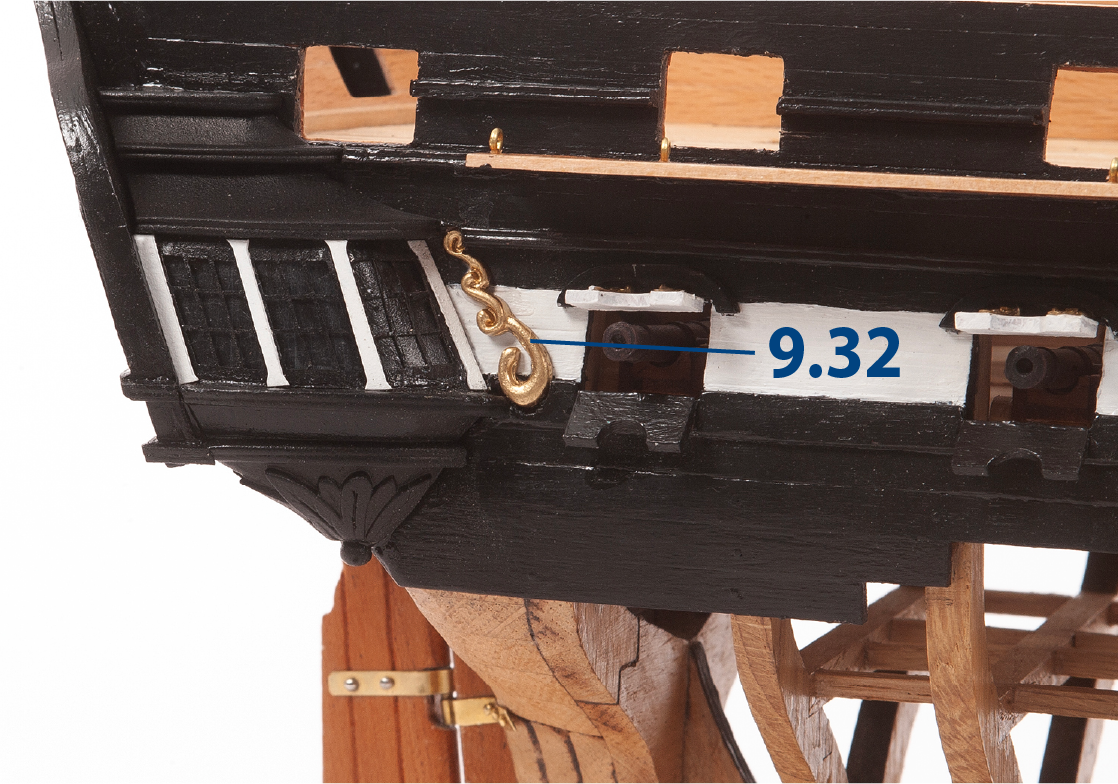
Passo 13
Eseguite gli aggiustamenti necessari per incollare le parti 9.32 e 9.33 (ornamenti di poppa) su entrambi i lati dello scafo.
Passo 14
Incolla gli ornamenti che hai dipinto durante l’assemblaggio del pacco 08 sullo specchio di poppa.
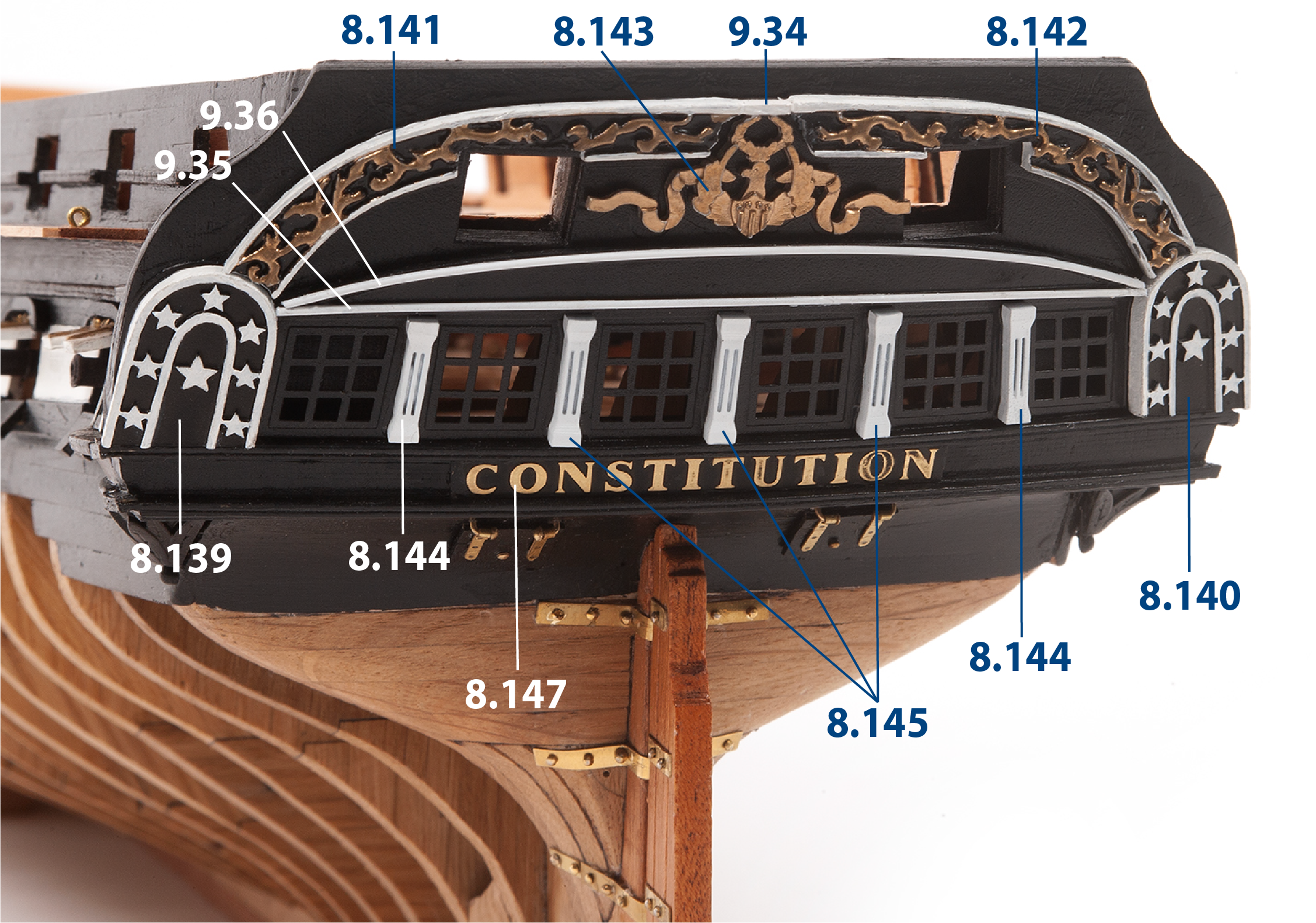
Realizza le parti 9.34–9.36, dipingile di bianco, poi incollale sullo specchio di poppa.
| 9.34 | 2 x 2 x 6 mm legno di tiglio |
| 9.35 | ø1 x 114 mm ottone |
| 9.36 | ø1 x 118 mm ottone |
Passo 1
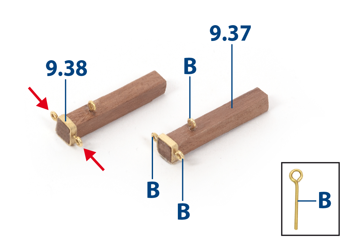
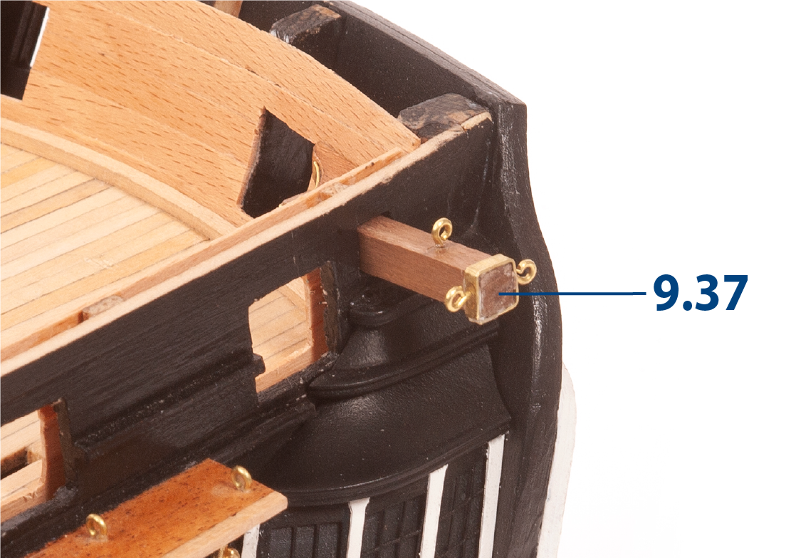
Completa i due argani utilizzando le parti 9.37 (6 × 6 × 32 mm in noce africano) e 9.38 (2 × 24 mm in ottone), quindi fora un foro ø0,75 mm in ciascun argano per inserire i golfari (B), come mostrato.
Passo 2
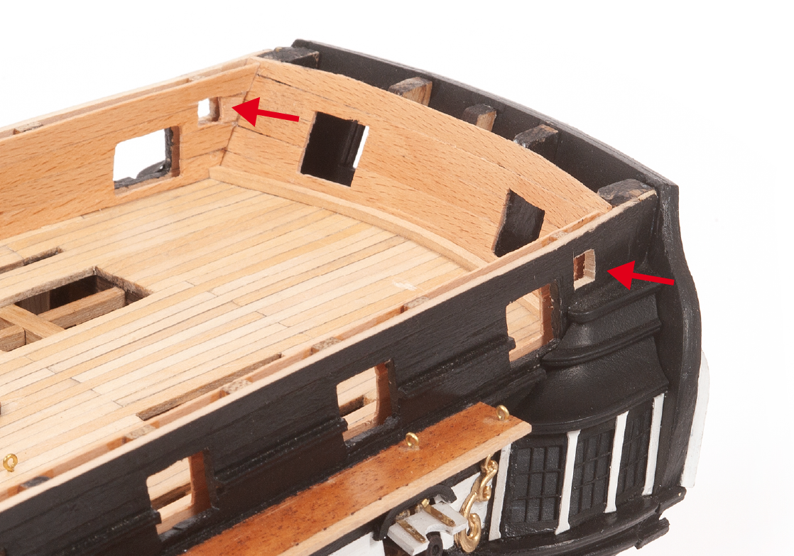
Utilizzando il piano di elevazione, fora i fori e poi allargali per creare le aperture destinate agli argani.
Passo 3
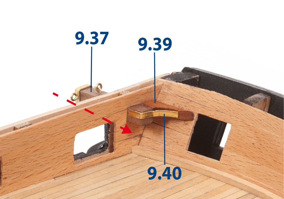
Inserisci un argano e incolla la parte 9.39. Taglia la parte 9.40 (2 x 21 mm in ottone) alla lunghezza richiesta e incollala come mostrato nella foto.
Passo 4
Procedi allo stesso modo per fissare le parti sull'altro lato dello scafo.
Passo 5
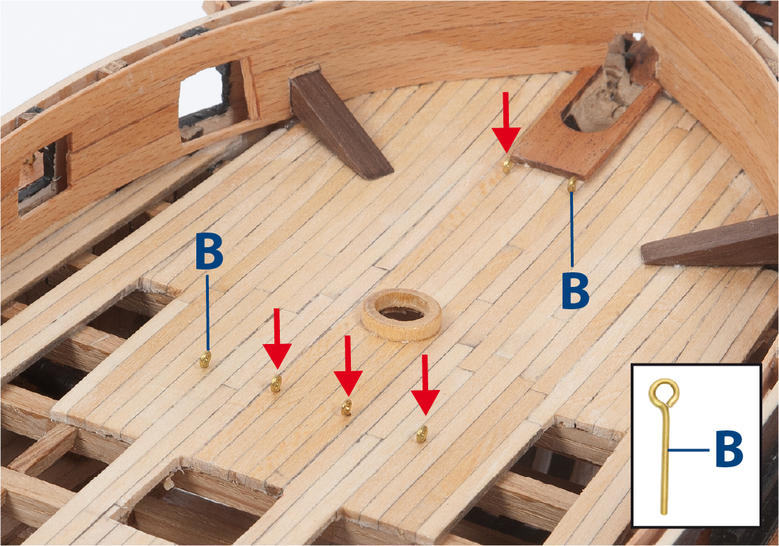
Utilizzando la pianta del ponte, inserisci e incolla i golfari (B), come mostrato.
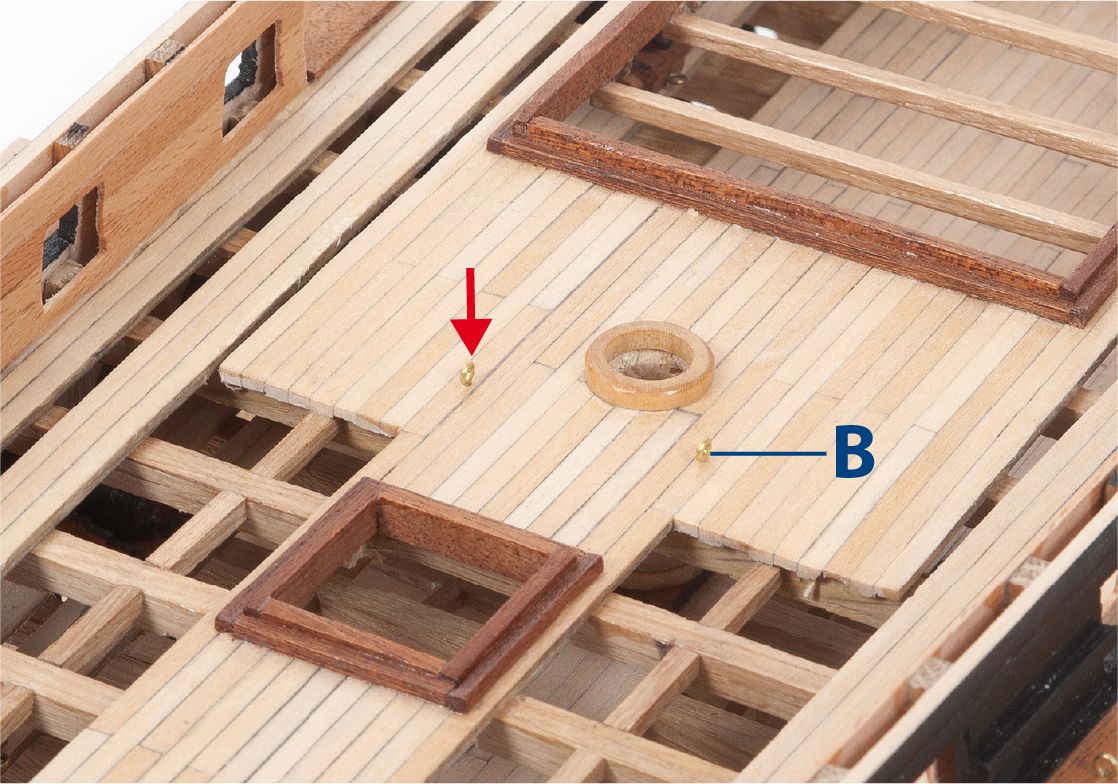
Passo 6
Continua a inserire i pitoni (B) come mostrato.
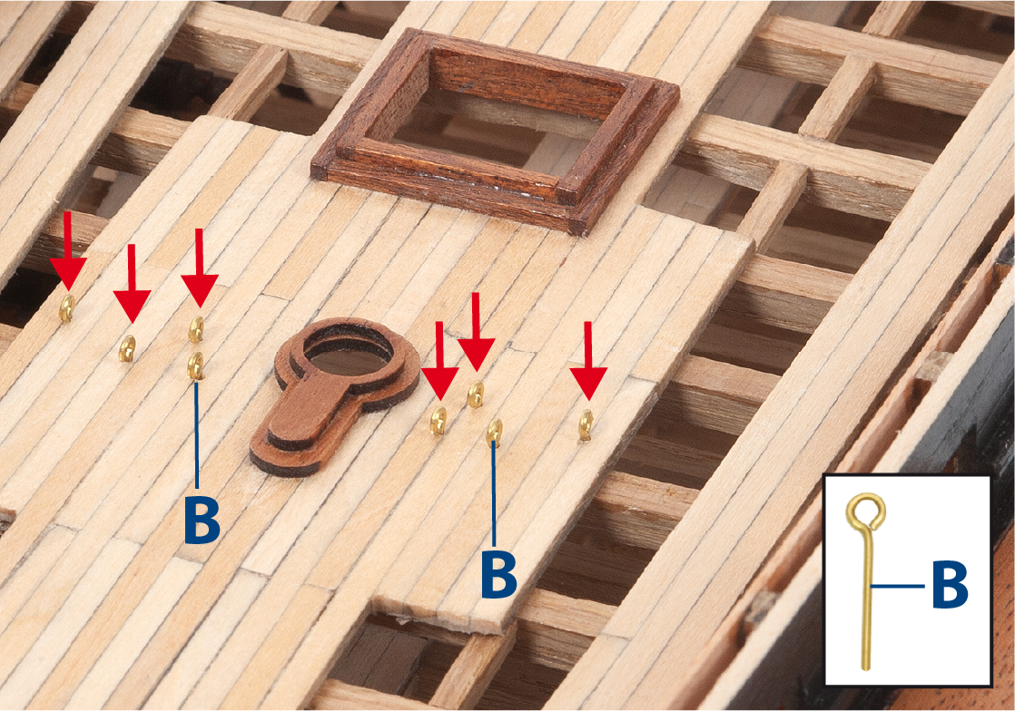
Passo 7
Inserisci i pitoni (B) nell’area dell’albero di mezzana come mostrato.
Passo 8
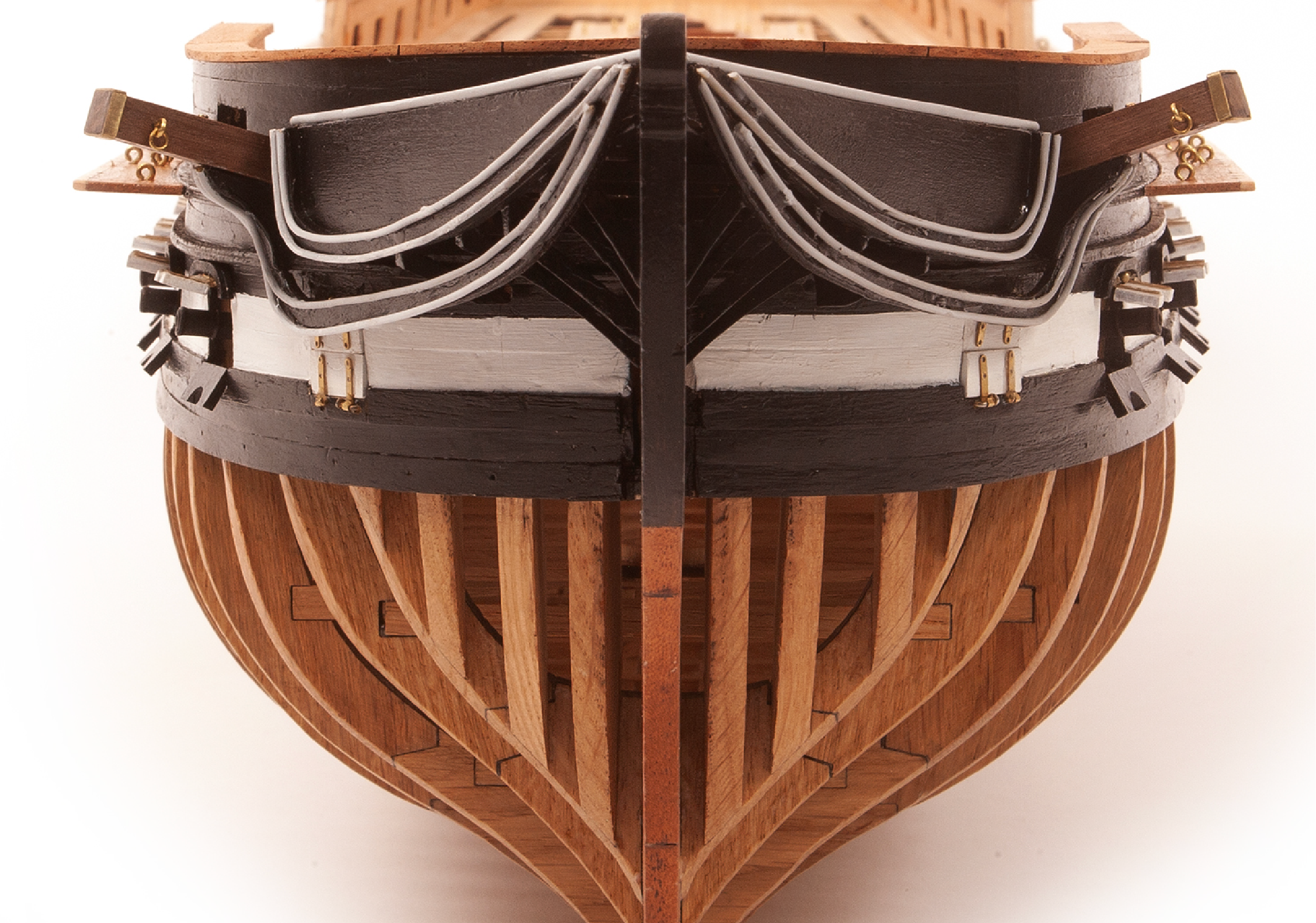
Taglia il filo di ottone alle lunghezze indicate qui sotto, dipingilo di bianco e incollalo sullo scafo come mostrato. Ripeti questo passo sull’altro lato dello scafo.
| 9.41: ø1 x 137 mm | 9.44: ø1 x 133 mm |
| 9.42: ø1 x 135 mm | 9.45: ø1,5 x 55 mm |
| 9.43: ø1 x 135 mm |

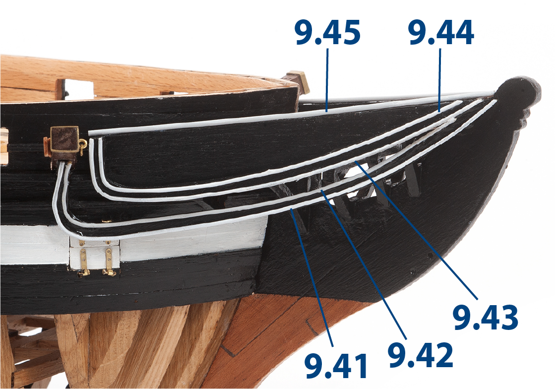
Passo 9
Incolla le parti 9.46 e 9.47 su entrambi i lati dello scafo.
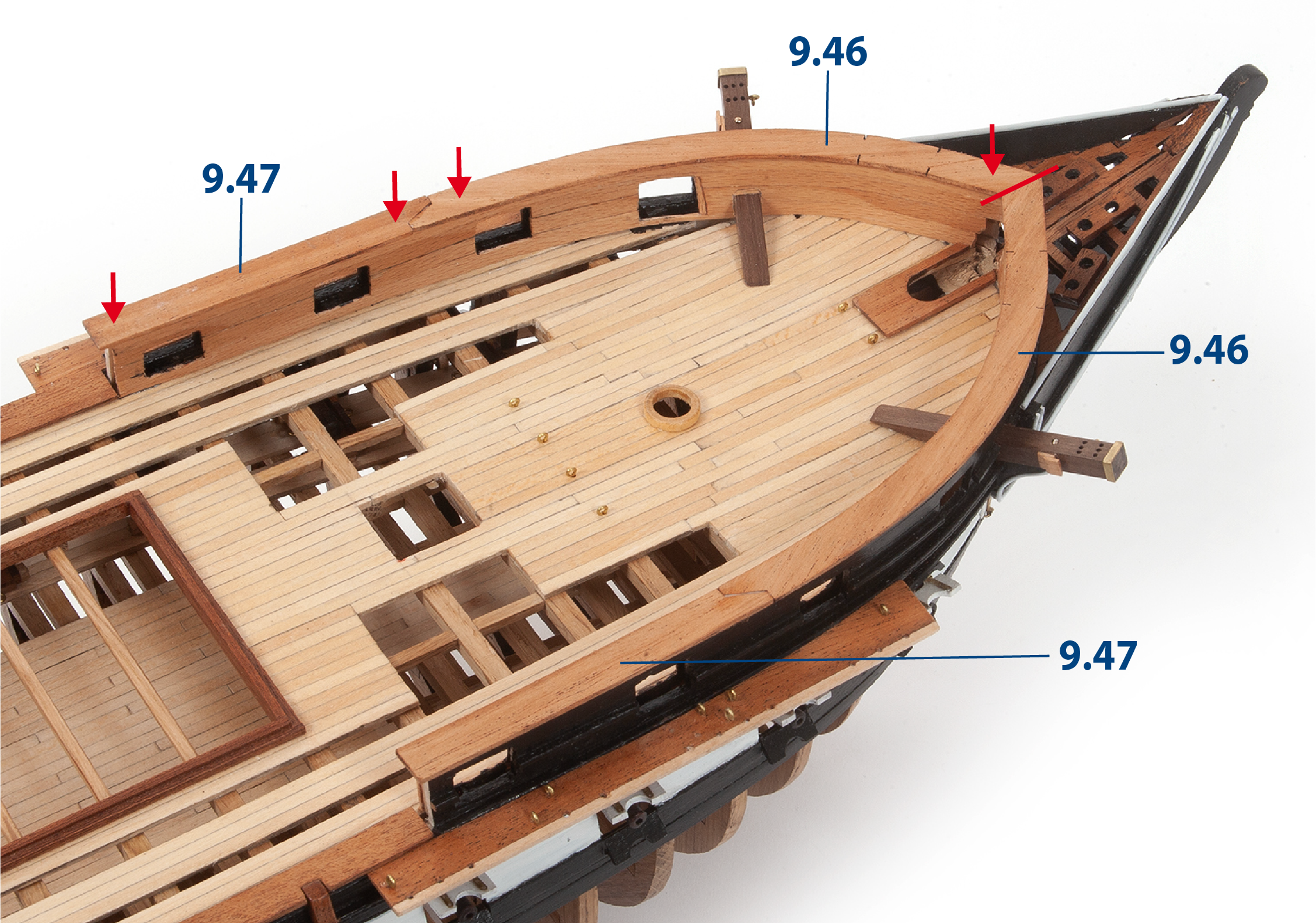
Passo 10
Questa foto mostra lo scafo con le parti di prua al loro posto.
Passo 1
Taglia le parti 9.46 seguendo le marcature del taglio laser.
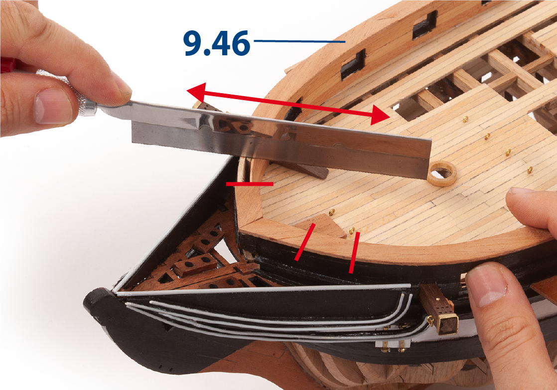
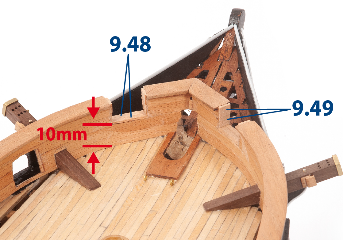
Passo 2
Ritaglia le aperture come mostrato nella foto. Taglia i pezzi 9.48 (1 x 5 x 10 mm di legno di tiglio) e 9.49 (1 x 5 x 8 mm di legno di tiglio) alle dimensioni indicate, poi incollale per rivestire i bordi delle aperture.
Passo 3
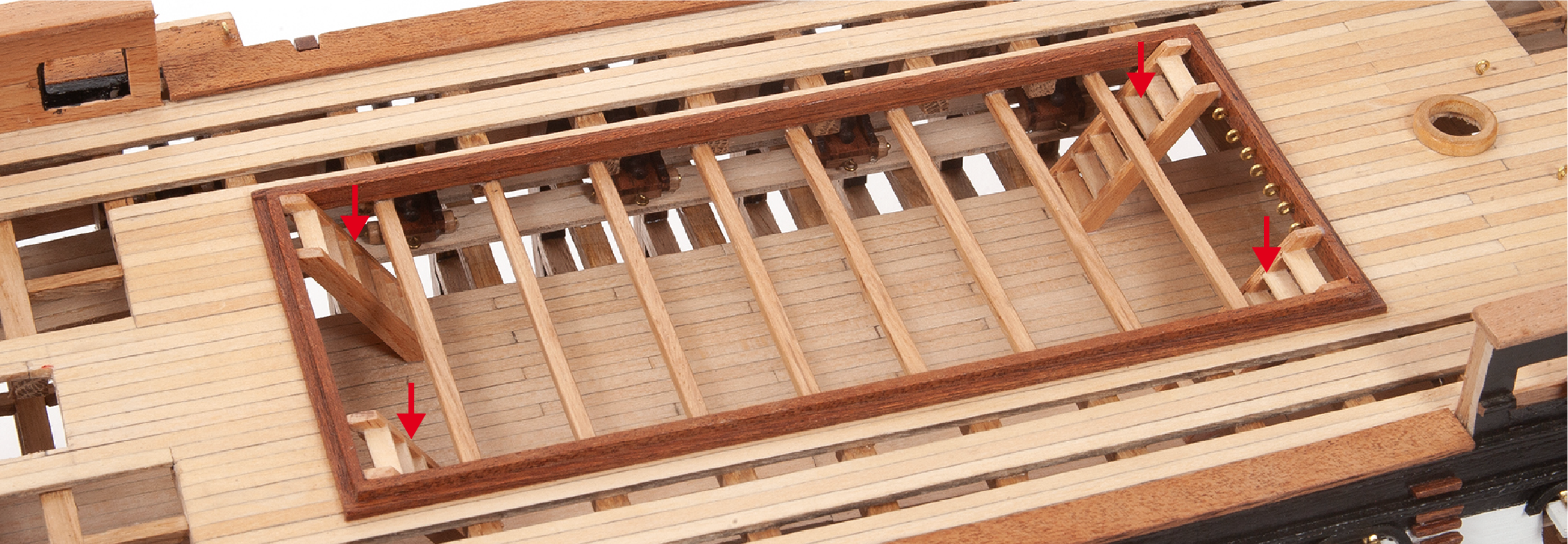
Recupera le scale larghe assemblate precedentemente. Verifica che si adattino correttamente e, se necessario, corregi l'altezza poi incollale facendo riferimento alla pianta del ponte.
Passo 4
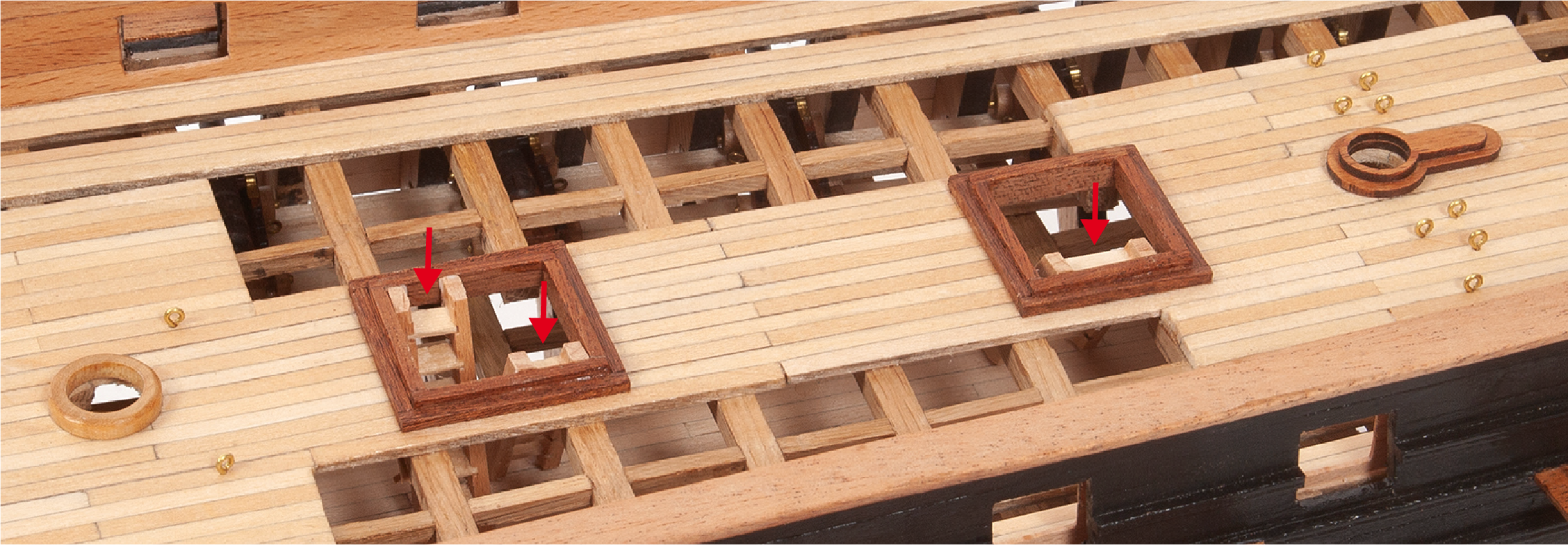
Regola e incolla le tre scale rimanenti nella zona di poppa come indicato sulla pianta del ponte.
Passo 5
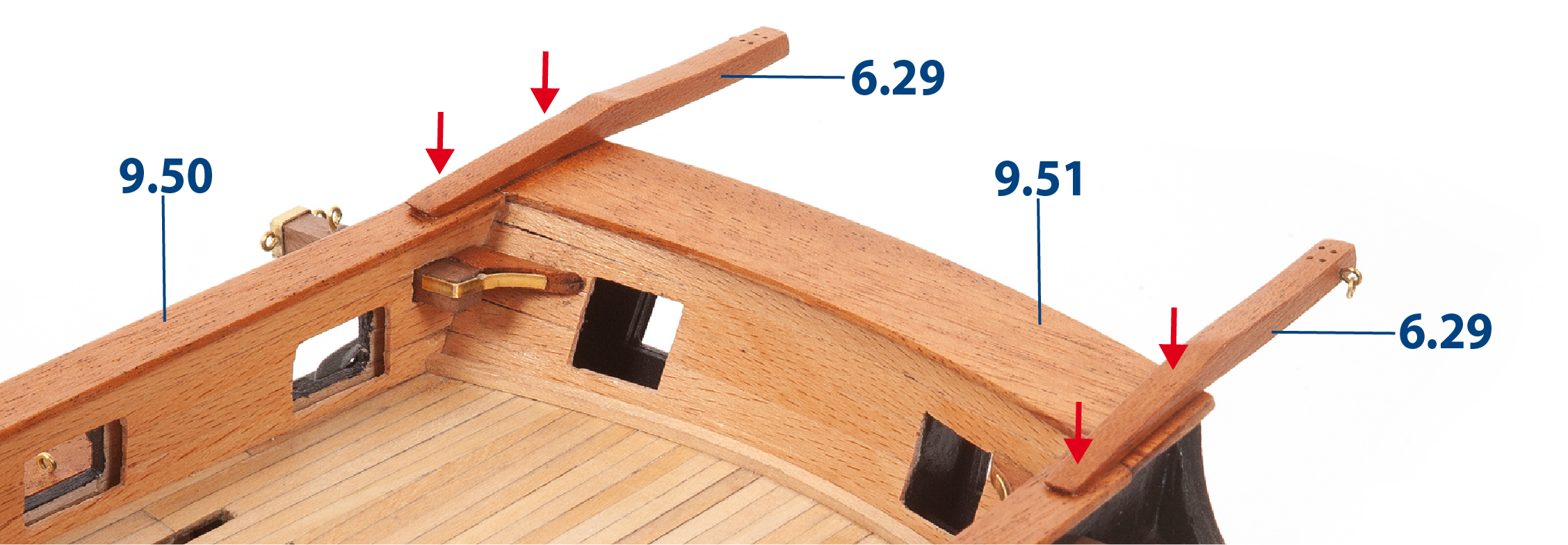
Riferendosi al piano e alle foto sottostanti, incolla le parti 9.50 e 9.51 e gli aregani 6.29 assemblati durante l'assemblaggio del pacco 06.
L’immagine sottostante mostra gli argani installati al contrario. Fare riferimento al proprio piano per l’installazione corretta.
Passo 6
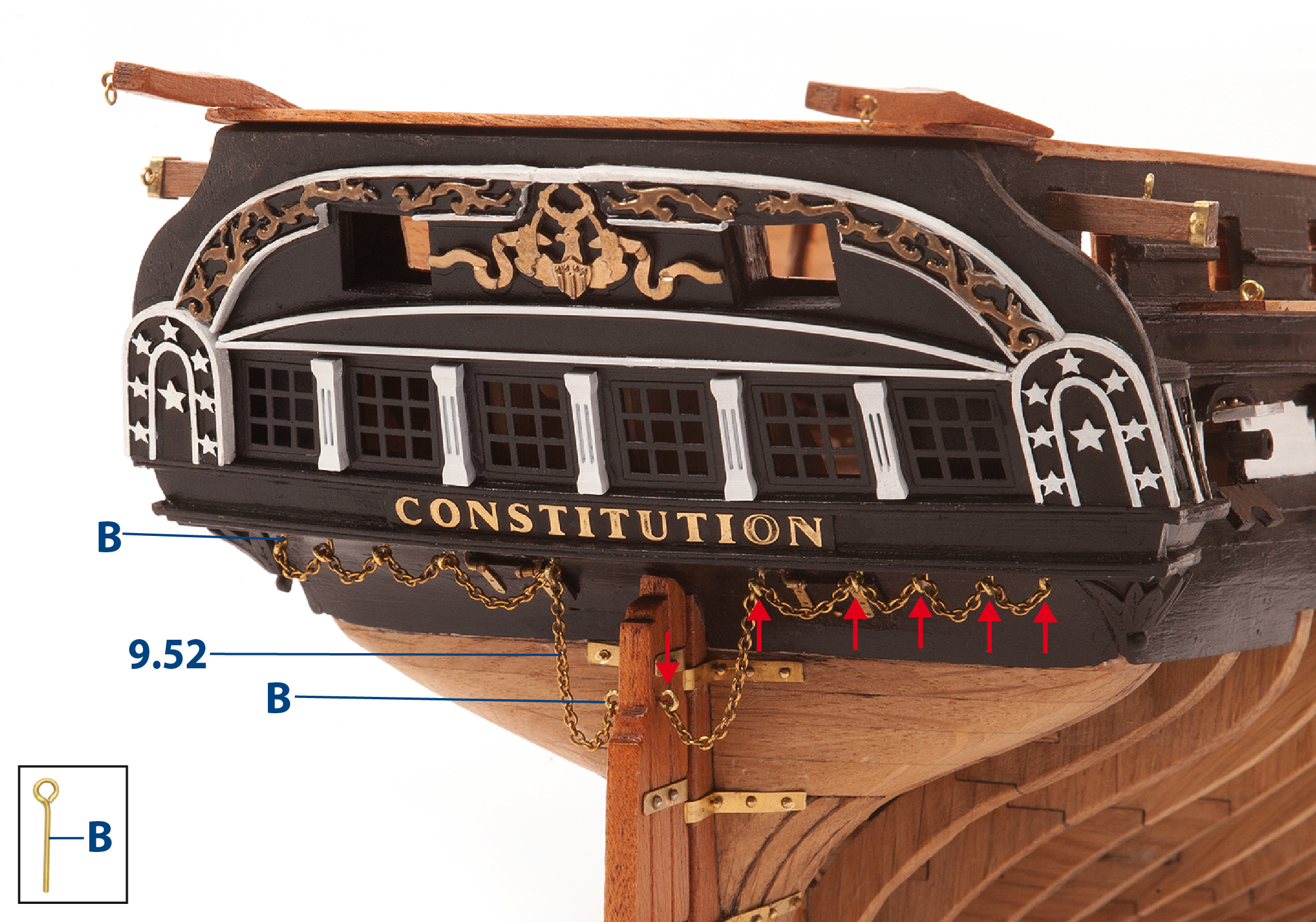
Fora i fori per inserire i pitoni (B). Fissa la catena 9.52 (1 x 300 mm) ai pitoni come mostrato nella foto.
Passo 1
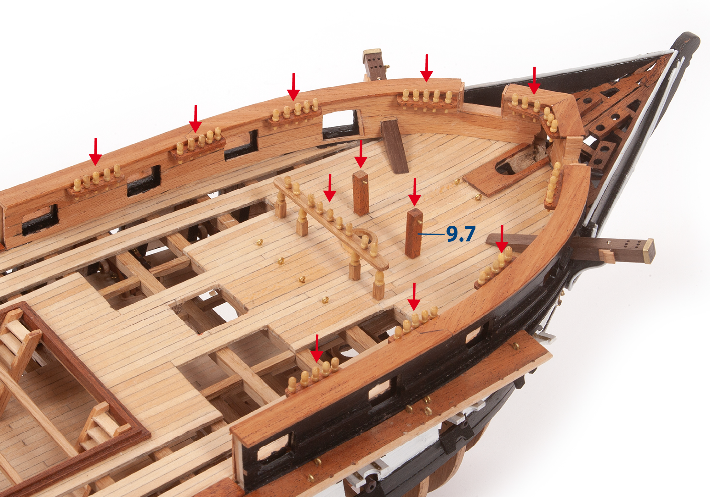
Recupera i banchi delle caviglie già assemblati nel pacco 06 e incollali come indicato sulla pianta del ponte. Quindi incolla le parti 9.7 sul ponte come mostrato.
Passo 2
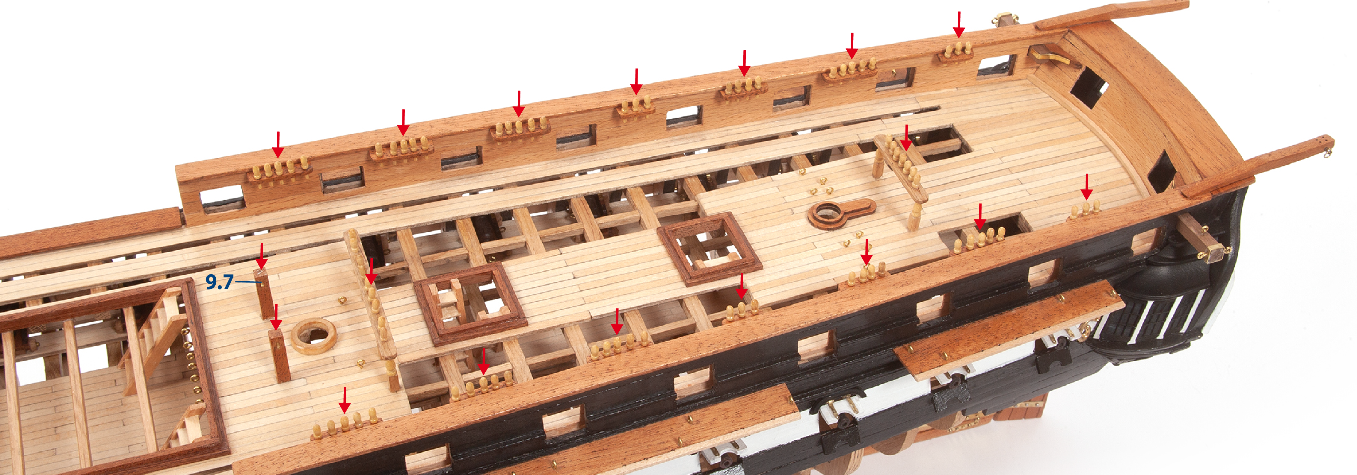
Continua a incollare i banchi delle caviglie sull’assemblaggio come mostrato nella foto.
Passo 3
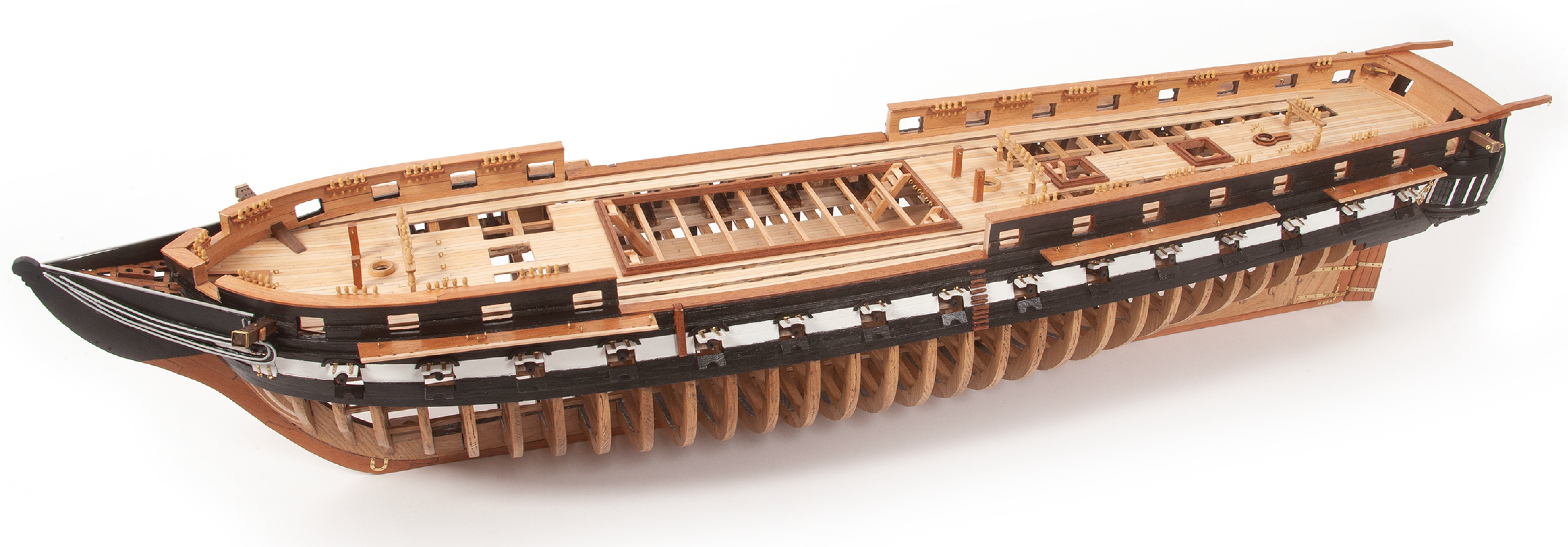
Ecco come appare la nave al termine dell’assemblaggio di questo pacco.