Pack 05
BUILD INSTRUCTIONS
Instructions for building your Cutty Sark model ship
Your model of the Cutty Sark is divided into 12 packs.
You will need to follow the step-by-step assembly photos, the plans and the explanatory texts below.
Please save the leftover materials from each pack for use when instructed to do so at a later stage of the assembly instructions.
The IP sheets displayed below are drawings of laser-cut parts and photo-etched brass parts and will serve as a guide for identification of some parts.
Use the PARTS REFERENCE table to help locate the parts.
The PL-00 templates (printed at 1/1 scale) will serve as a guide for building the frames.
Please check the list below to ensure you have all the tools required for building your wooden ship.
When removing a part, cut the ribs that join the part to the wooden plate with a cutter.
Remove the parts carefully so as not to break them.
Keep and store the parts in their frames. Only remove the parts you are working on in each step.
Extra support can be found on our forum.
PARTS LIST
| Material | Quantity | |
| Wooden Boards | ||
| 2002-21, 2002-23 | Wood | 2 |
| Wooden Strips | ||
| 2 x 5 x 600 mm | Lime wood | 20 |
| 1 x 3 x 600 mm | Lime wood | 10 |
| 2 x 3 x 600 mm | Lime wood | 5 |
| 2 x 2 x 600 mm | Mahogany | 10 |
| Parts | ||
| Eyebolt (15 mm) (B) | Brass | 600 |
| Belaying pin (10 mm) (J) | Wood | 180 |
| Grating (8.27) | Wood | 64 |
| Hatch (9.23) | Brass | 2 |
| Hawsehole (8.50) | Brass | 6 |
| Anchor (44 mm) (9.35) | Metal | 2 |
| Anchor stock (9.36) | Metal | 2 |
| Bell (8.11) | Brass | 2 |
| Sheave (MT8) | Brass | 2 |
| Ring (ø6 mm) (9.44) | Brass | 4 |
| Ring (ø4 mm) (O) | Brass | 75 |
| Ring (ø3 mm) (H) | Brass | 200 |
| Pin rail (8.6) | Brass | 2 |
| Large pin rail (8.5) | Brass | 4 |
| Rivet 2 x 5 mm (5.33 / 6.40 / 7.10) | Brass | 90 |
| Acetate sheet (75 x 40 mm) | 2 | |
| Pin (A) | Brass | 2000 |
| Paint | ||
| White (30 ml) | Acrylic | 1 |
| Black (30 ml) | Acrylic | 1 |
| Primer (30 ml) | Acrylic | 1 |
Tools you will need: cutting mat, pencil, cutting knife, fine-grit sandpaper or sponge sandpaper, file, white wood glue, super glue (cyanoacrylate glue), masking tape, set square, hacksaw, sanding block, 30 cm steel ruler, clamps, moulding scriber tool
PACK 05 - PARTS IDENTIFICATION
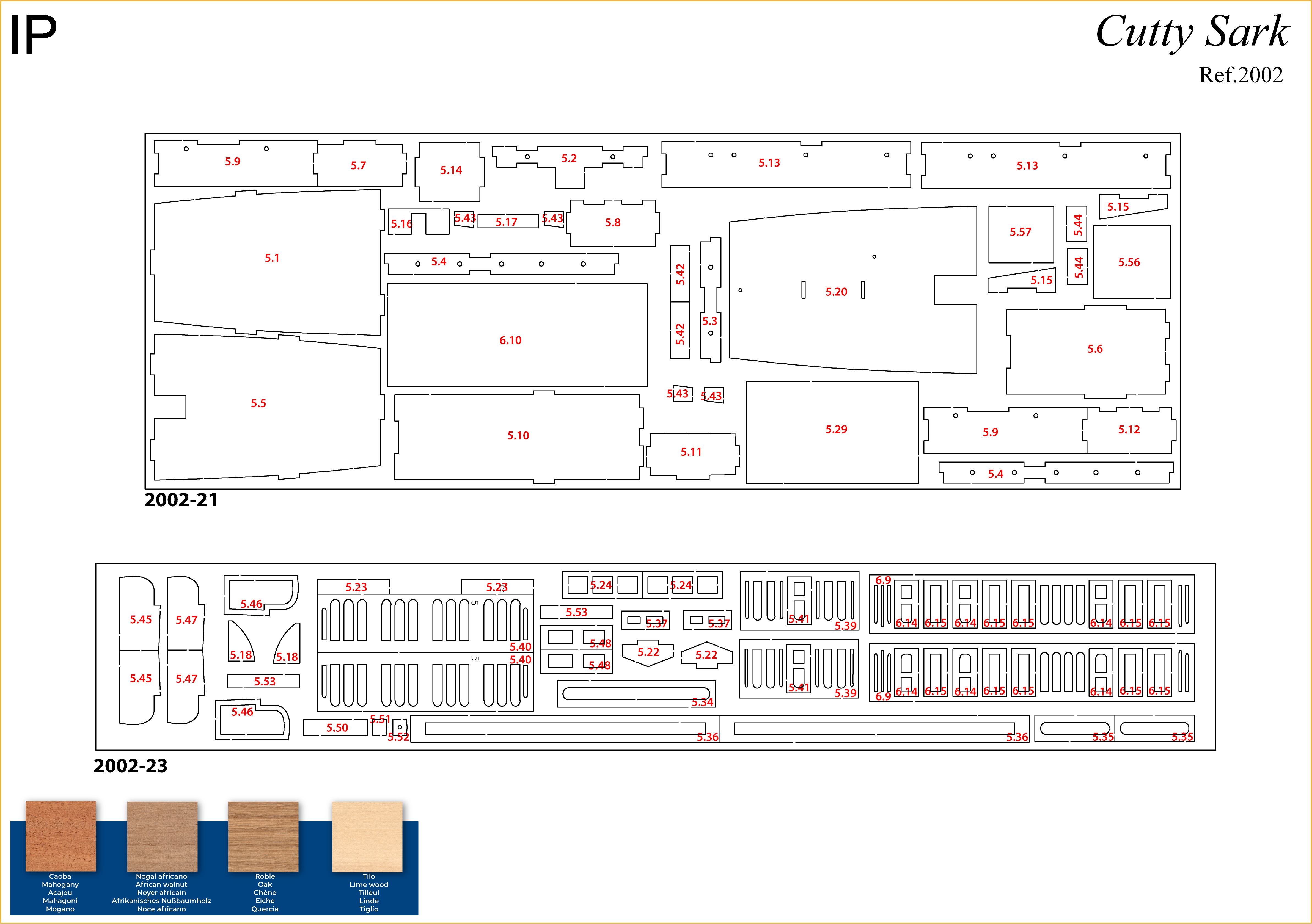
PARTS REFERENCE
PART NO. | REFERENCE | PART NO. | REFERENCE | PART NO. | REFERENCE |
| 5.1 | 2002-21 | 5.16 | 2002-21 | 5.42 | 2002-21 |
| 5.2 | 2002-21 | 5.17 | 2002-21 | 5.43 | 2002-21 |
| 5.3 | 2002-21 | 5.18 | 2002-23 | 5.44 | 2002-21 |
| 5.4 | 2002-21 | 5.20 | 2002-21 | 5.45 | 2002-23 |
| 5.5 | 2002-21 | 5.22 | 2002-23 | 5.46 | 2002-23 |
| 5.6 | 2002-21 | 5.23 | 2002-23 | 5.47 | 2002-23 |
| 5.7 | 2002-21 | 5.24 | 2002-23 | 5.48 | 2002-23 |
| 5.8 | 2002-21 | 5.29 | 2002-21 | 5.50 | 2002-23 |
| 5.9 | 2002-21 | 5.34 | 2002-23 | 5.51 | 2002-23 |
| 5.10 | 2002-21 | 5.35 | 2002-23 | 5.52 | 2002-23 |
| 5.11 | 2002-21 | 5.36 | 2002-23 | 5.53 | 2002-23 |
| 5.12 | 2002-21 | 5.37 | 2002-23 | 5.56 | 2002-21 |
| 5.13 | 2002-21 | 5.39 | 2002-23 | 5.57 | 2002-21 |
| 5.14 | 2002-21 | 5.40 | 2002-23 | ||
| 5.15 | 2002-21 | 5.41 | 2002-23 |
For extra support and guidance, John Builds Iconic Military Models demonstrates his build of the Cutty Sark on his YouTube channel, sharing 30+ years of wooden ship-building experience. Experts can be found on our Forum.
Step 1
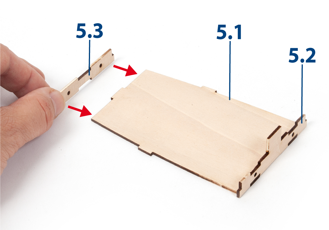
Remove parts 5.1 to 5.5 and sand them with fine-grit sandpaper. Then glue parts 5.2 and 5.3 to part 5.1.

Step 2
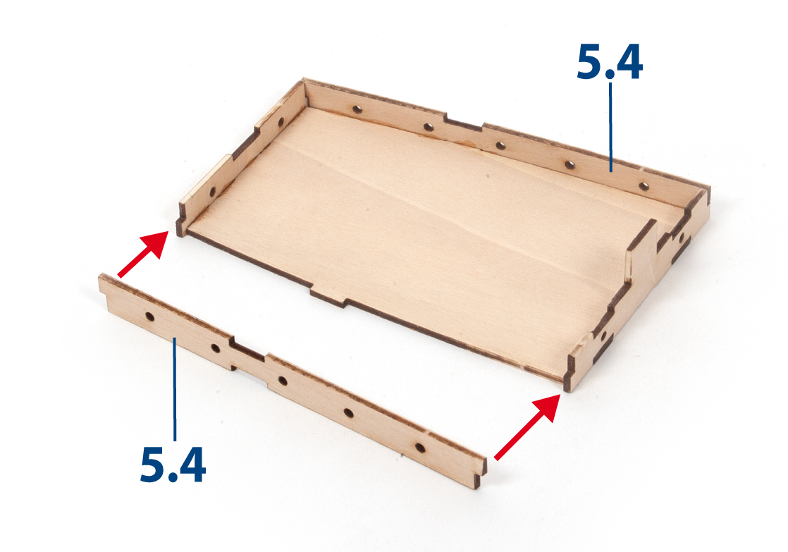
Glue both parts 5.4 to the assembly.
Step 3
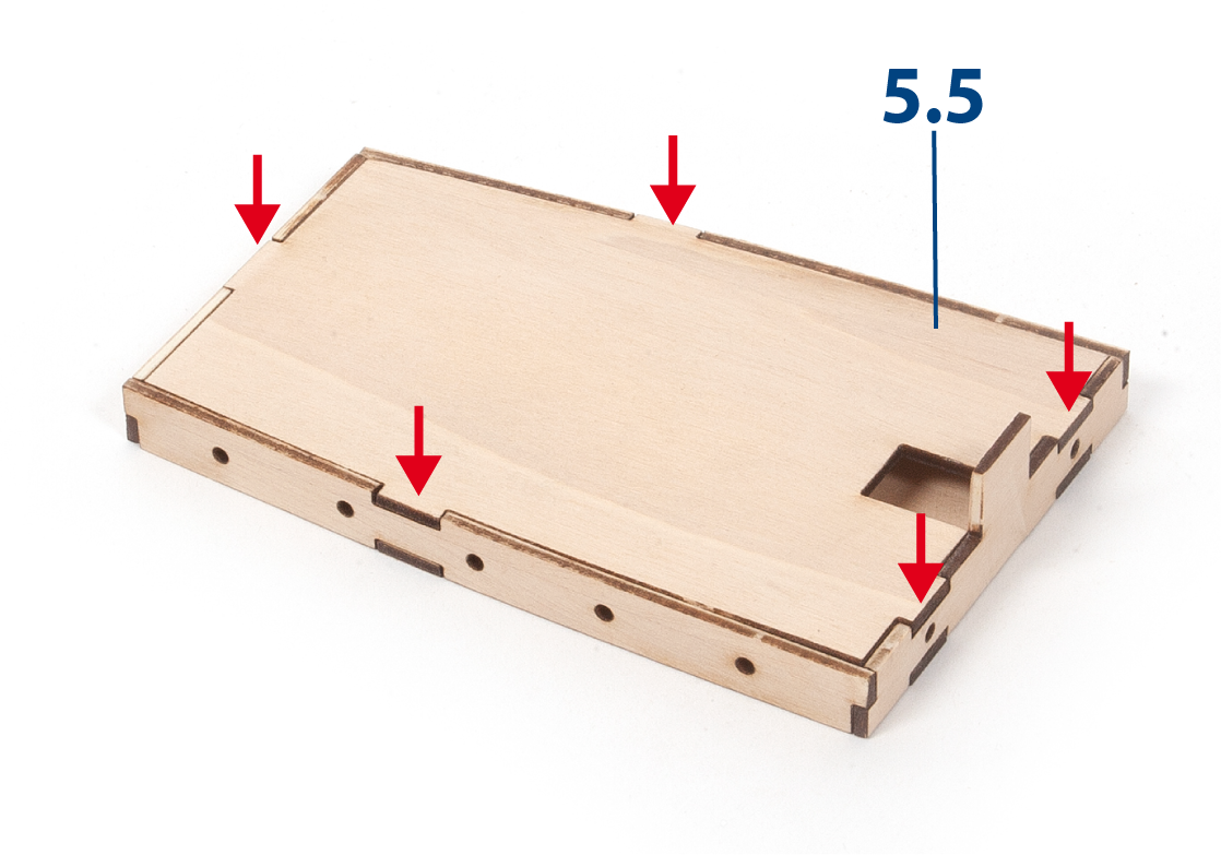
Glue part 5.5 to close the poop deckhouse assembly.
Step 4
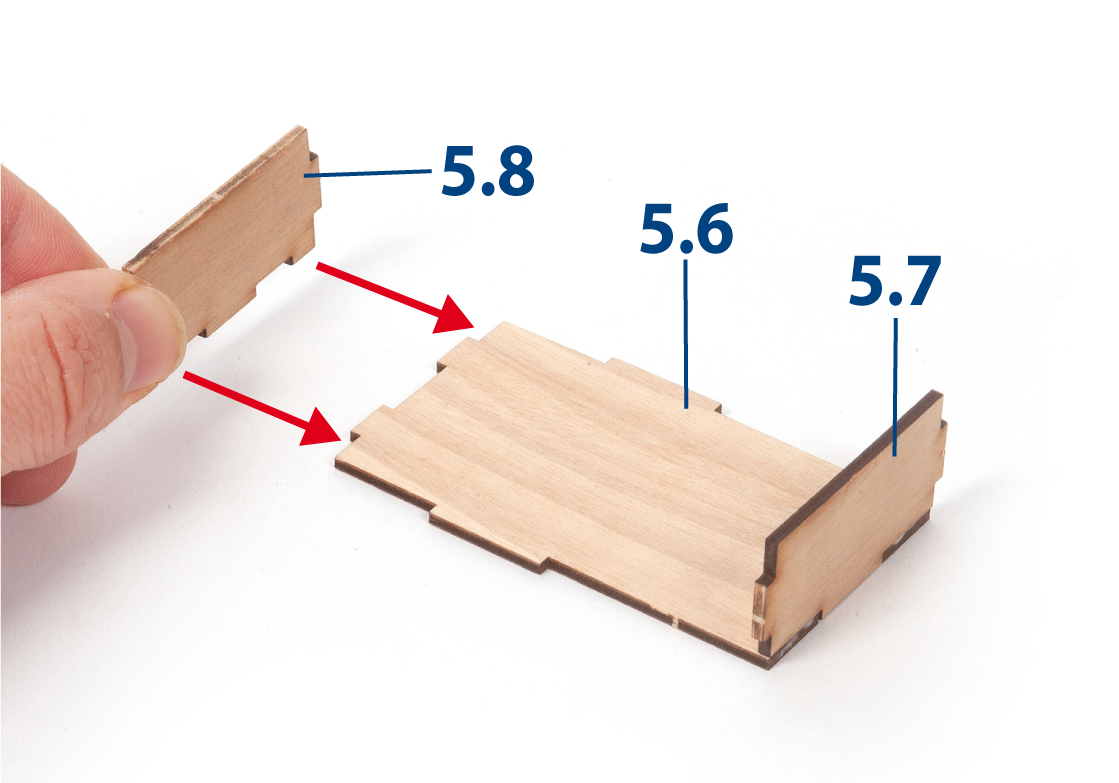
Glue parts 5.7 and 5.8 to part 5.6.
Step 5
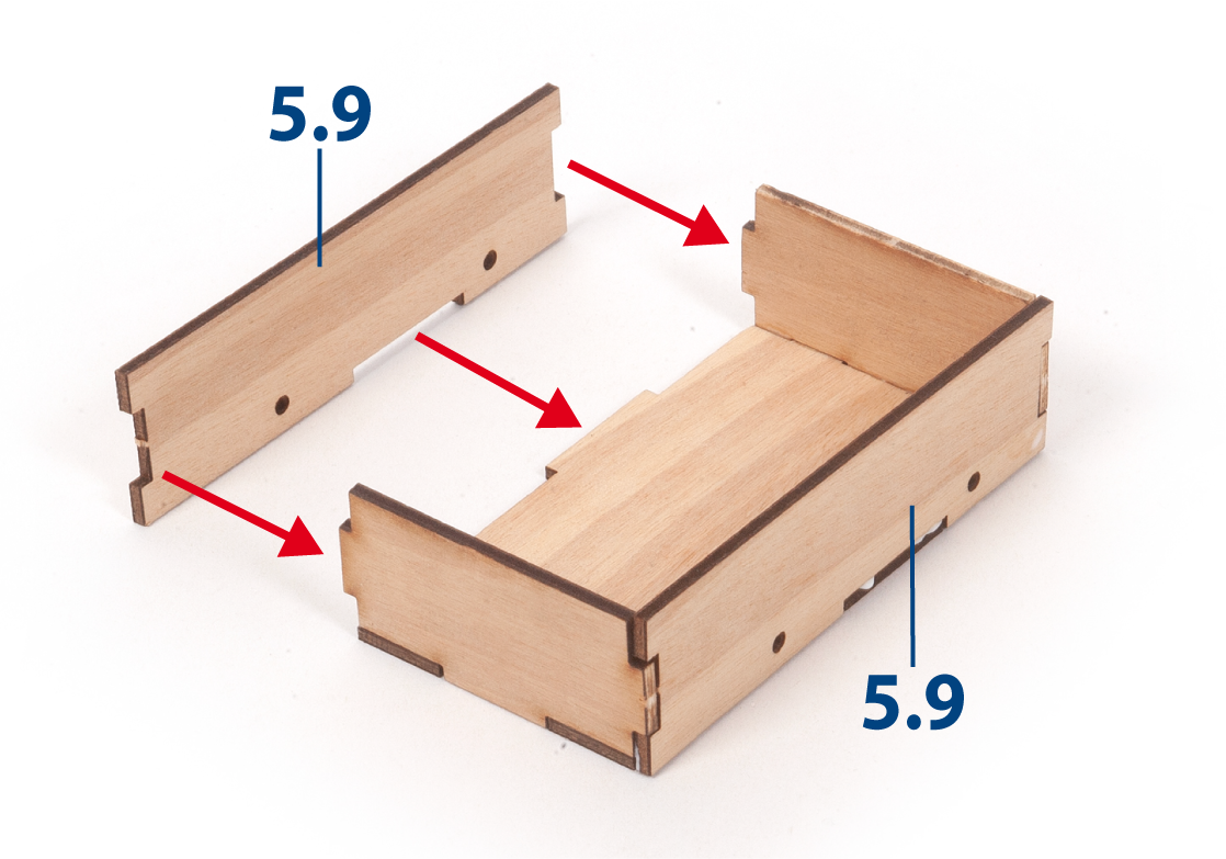
Glue both parts 5.9 to the assembly.
Step 6
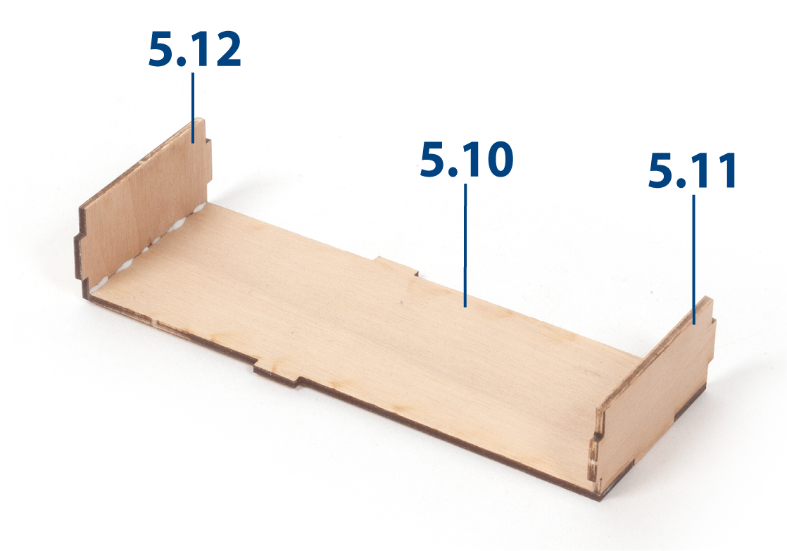
Glue parts 5.11 and 5.12 to part 5.10.
Step 7
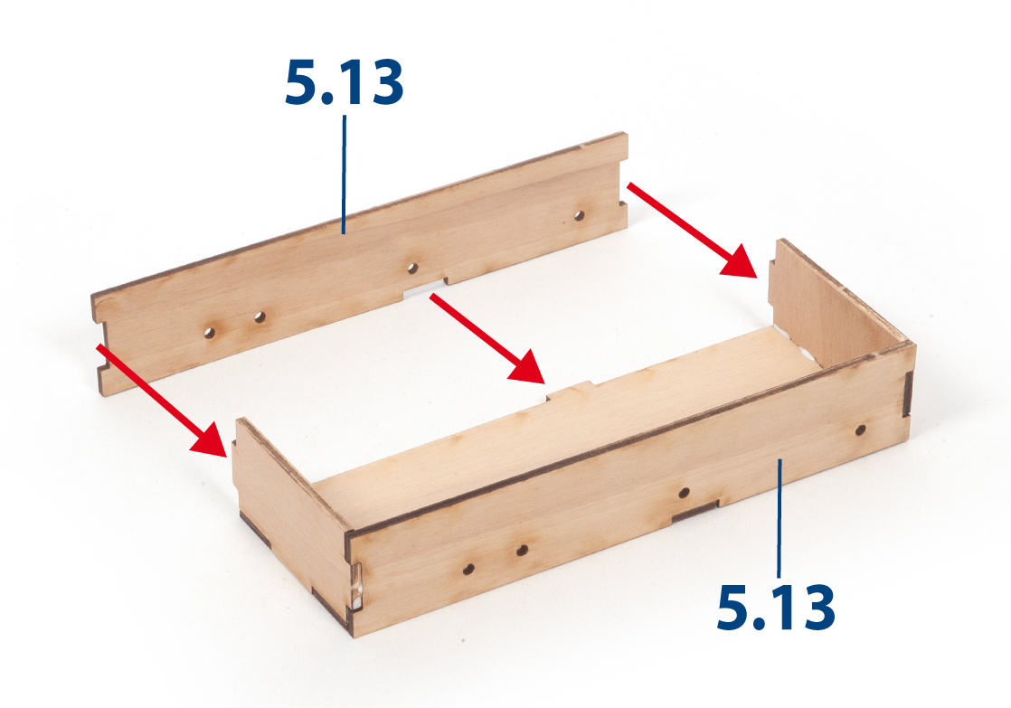
Glue both parts 5.13 to the assembly.
Step 8
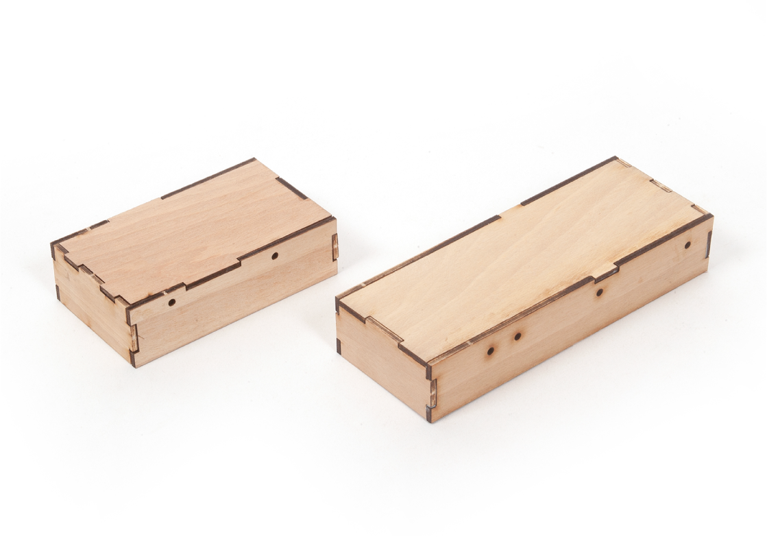
This image shows the aft deckhouse and the fore deckhouse assemblies at this stage.
Step 9
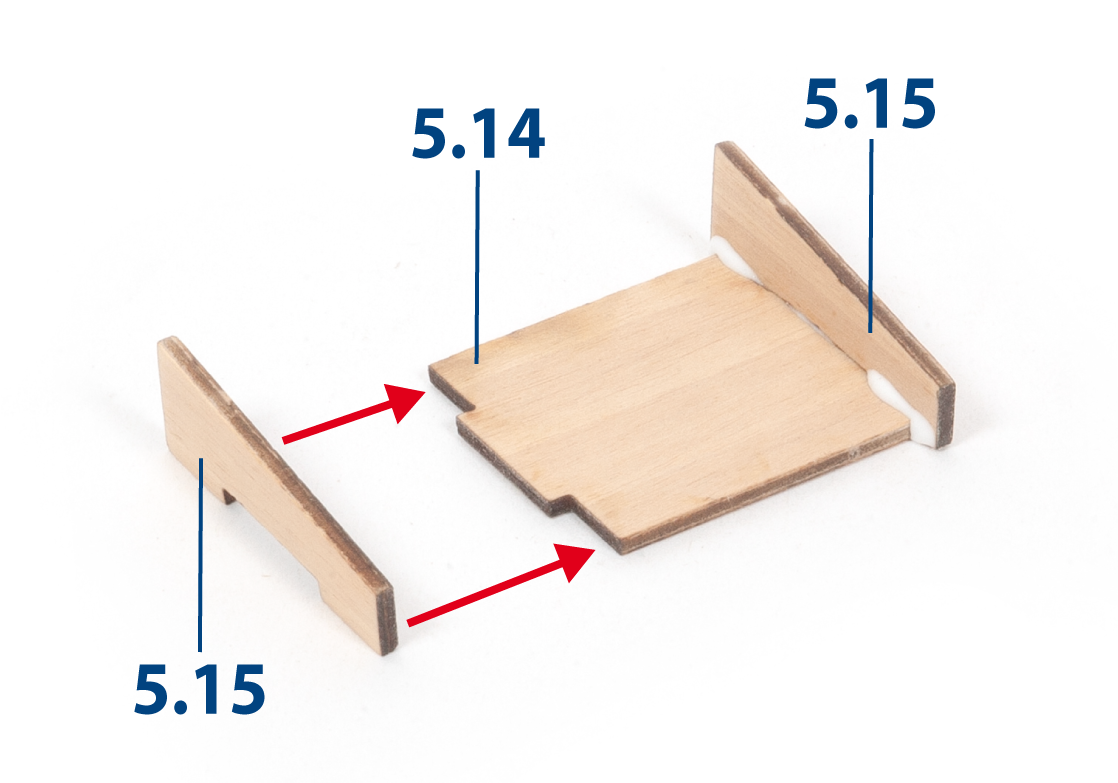
Glue both parts 5.15 to part 5.14.
Step 10
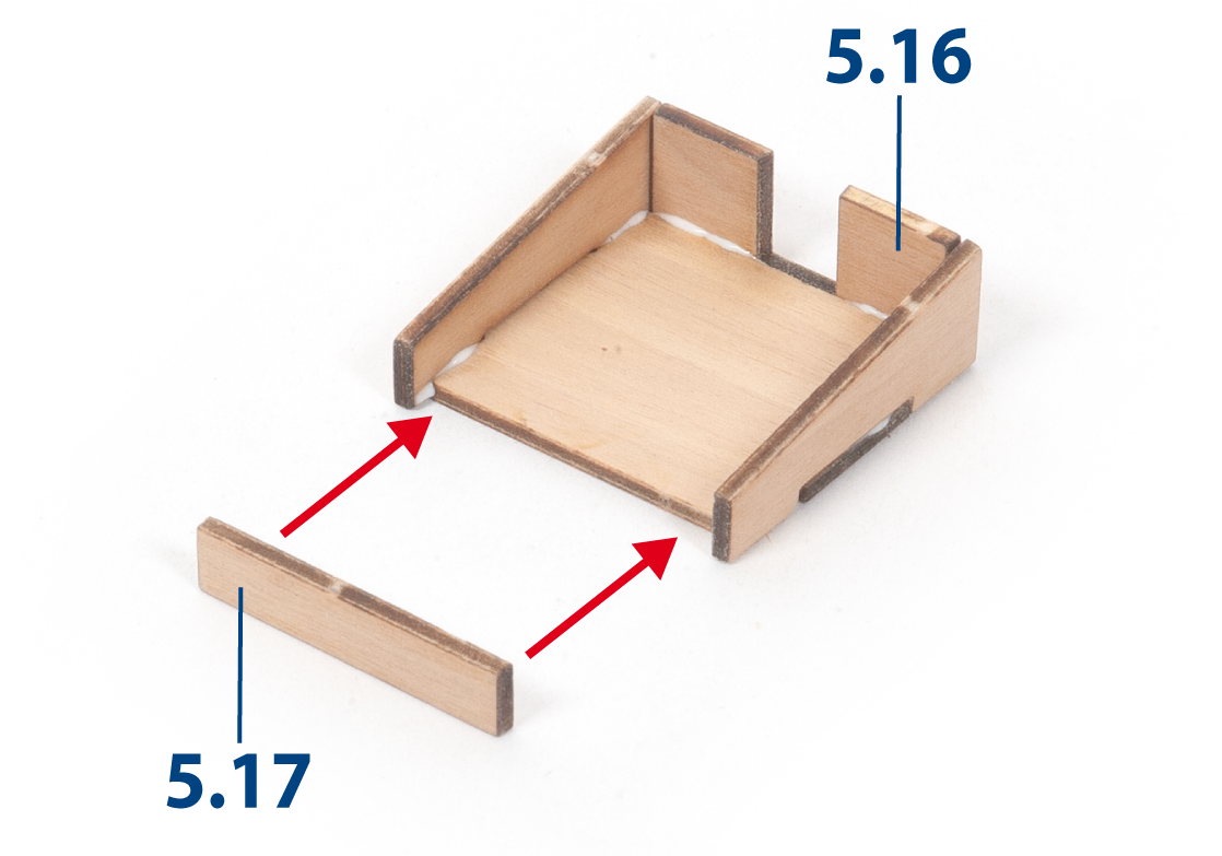
Glue parts 5.16 and 5.17 to complete the aft hatch assembly.
Step 11
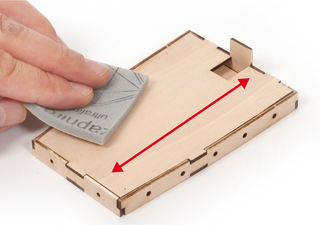
Sand the assemblies with fine-grit sandpaper. Some mahogany parts will be added to these assemblies later, as shown in the next stage.
Do not apply water-based wood filler if you intend to stain the assemblies instead of painting them.
Step 12
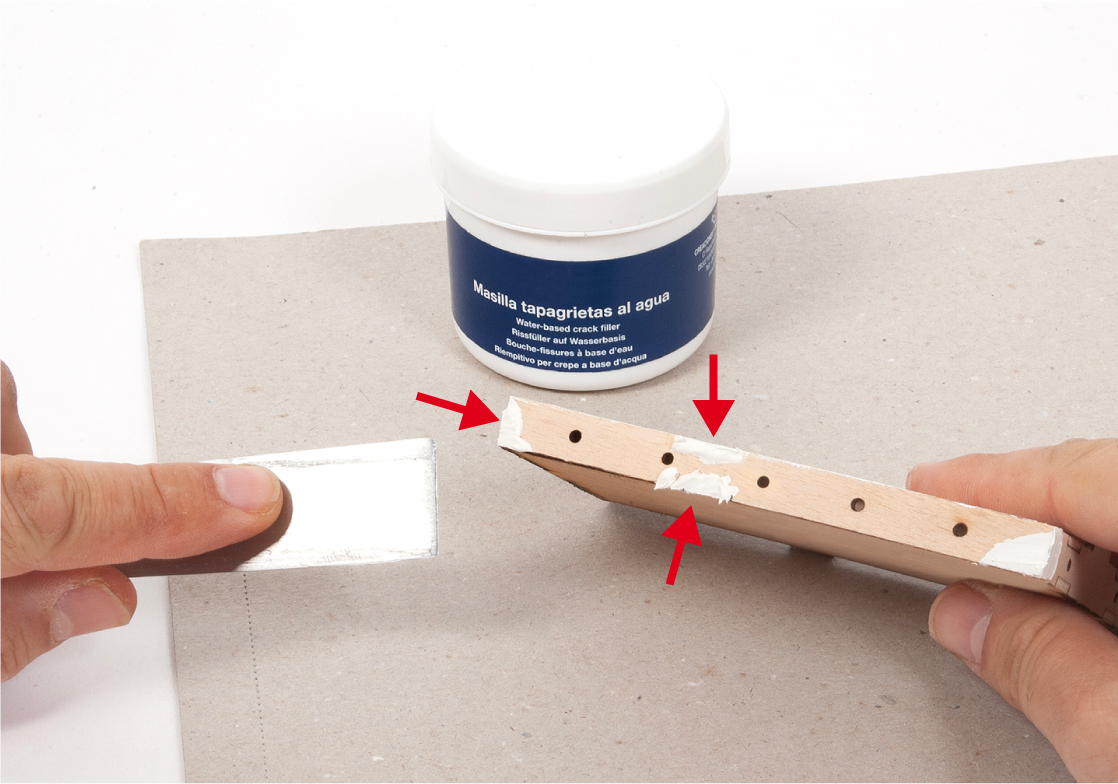
If you intend to paint the assemblies, apply water-based wood filler to the joints.
Step 13
Sand any excess wood filler from the assembly shown and even out the surfaces.
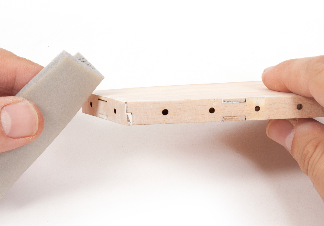
Step 14
Repeat the process for the remaining assemblies.
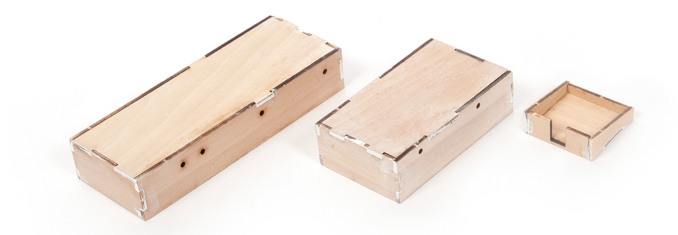
Step 15
If you applied wood filler earlier, apply a coat of primer and then paint the assemblies white.
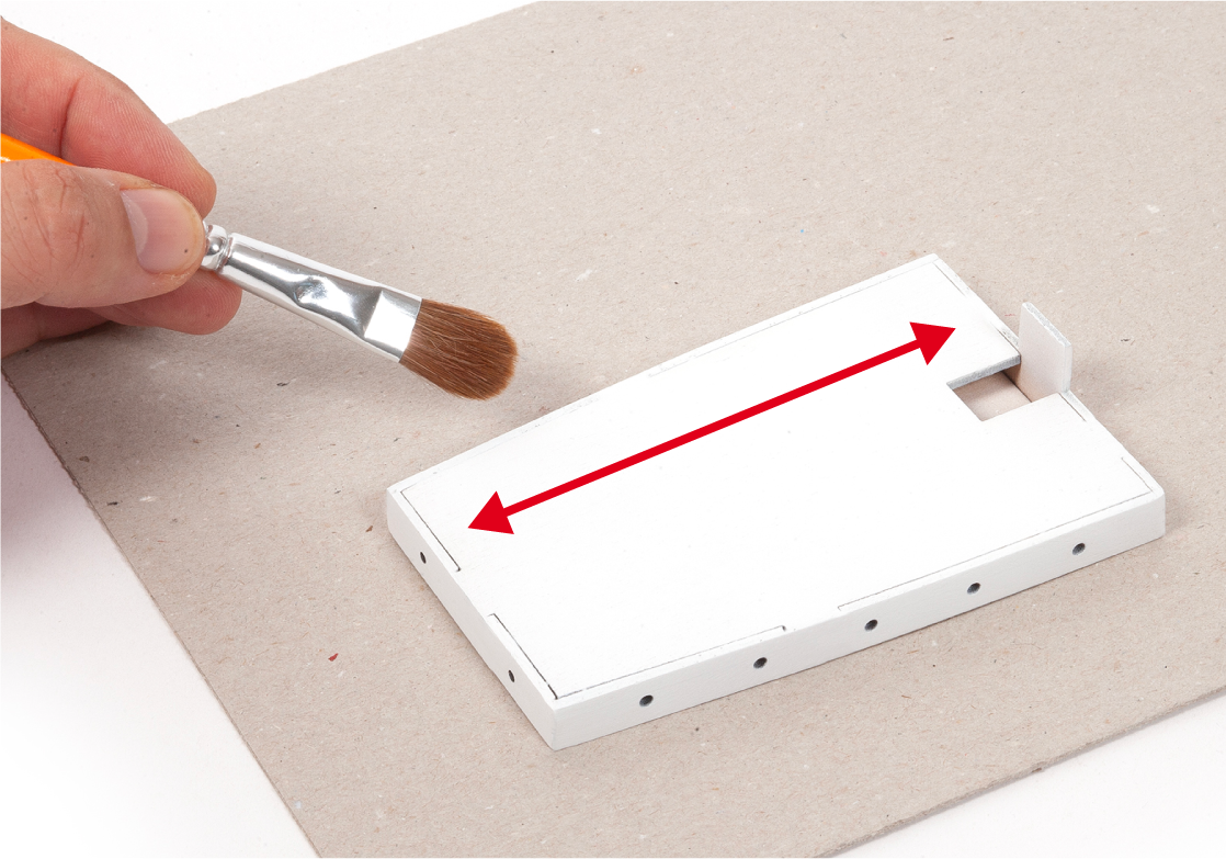
Step 1
Glue both parts 5.18 to the poop deckhouse assembly.
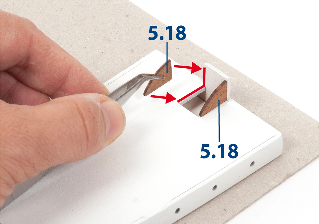
Step 2
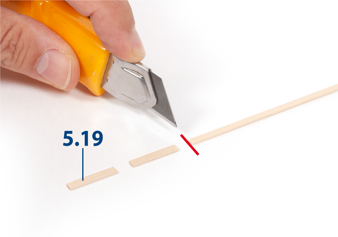
Sand a pair of 1 x 3 mm strips and cut parts 5.19 to length (1 x 3 x 17 mm).
Step 3
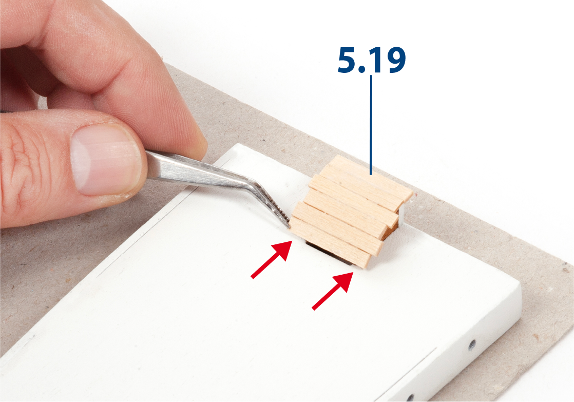
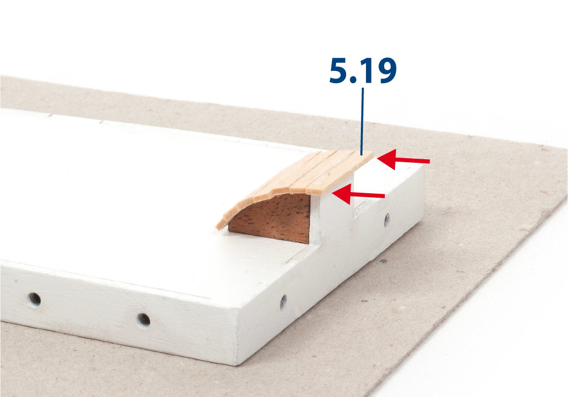
Glue parts 5.19 as shown.
Note that one of the parts 5.19 protrudes (see image b).
Step 4
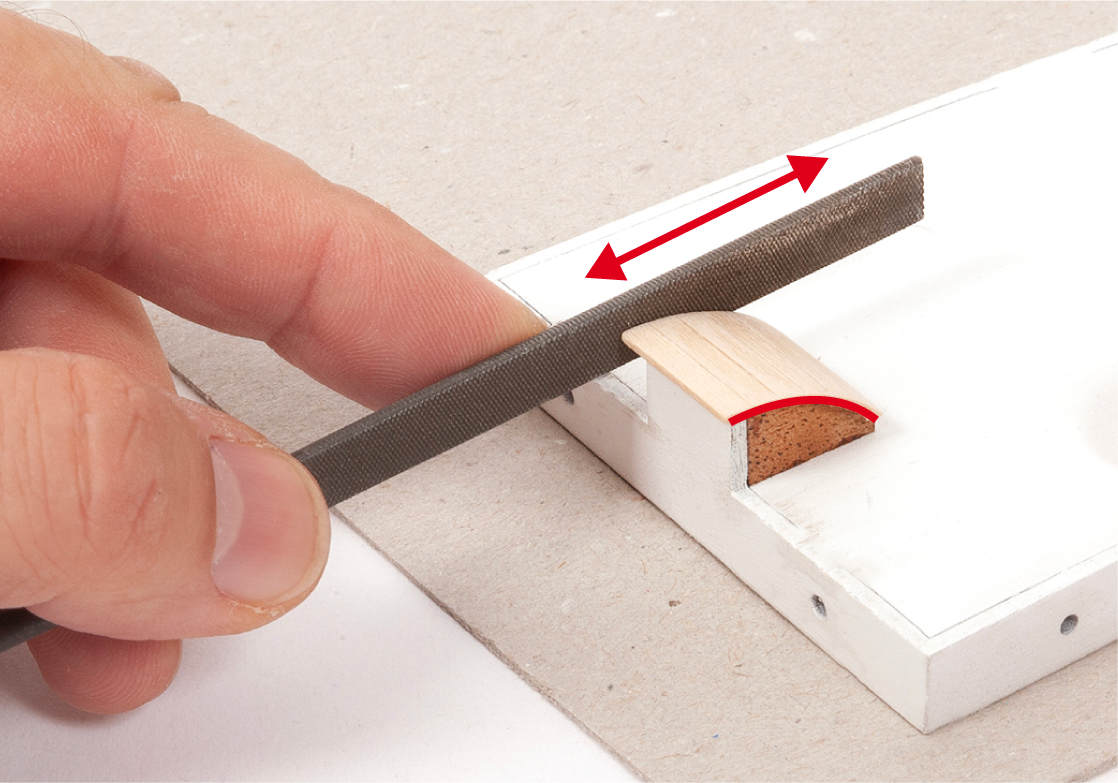
File the edges until they are even.
Step 5
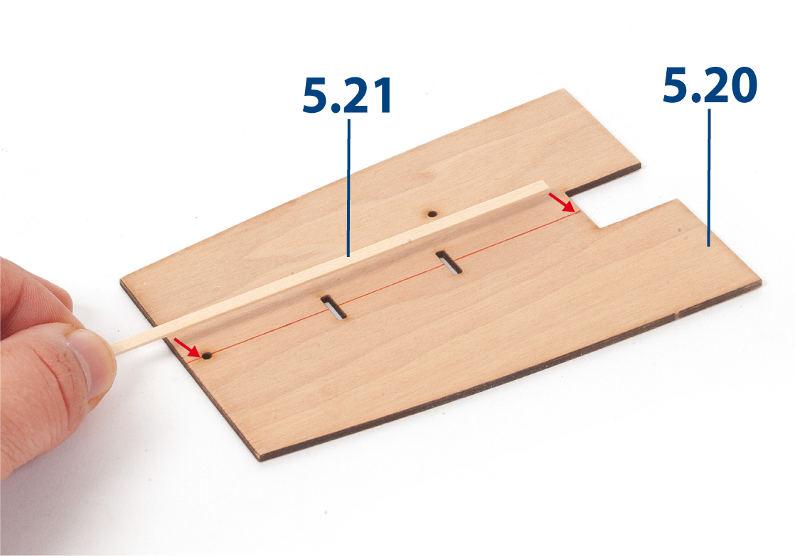
Glue part 5.21 (1 x 3 x 130 mm lime wood) centrally on part 5.20.
Step 6
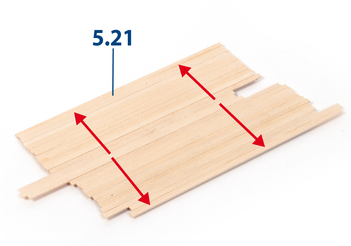
Glue additional parts 5.21 on either side of the first strip until the roof is completely covered. Use PVA glue for this step.
Step 7
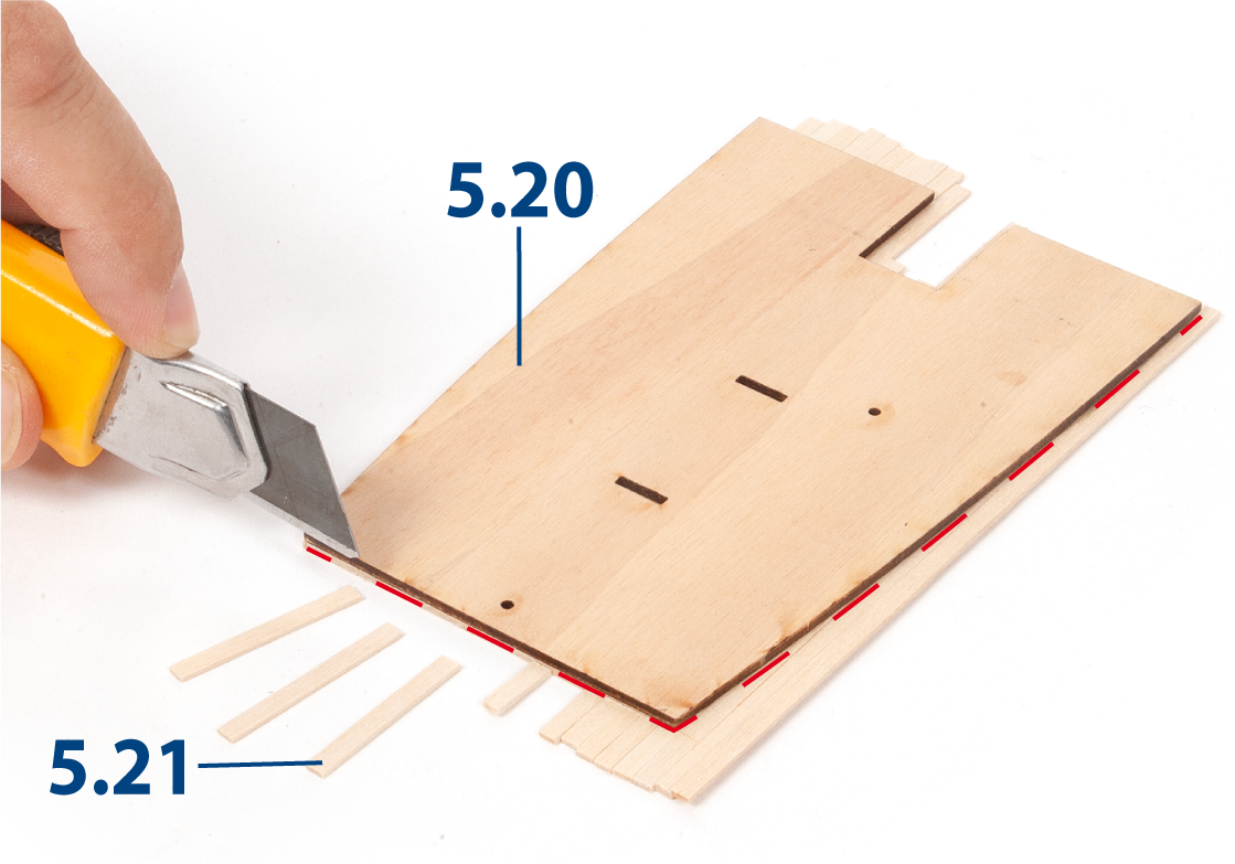
Turn the poop deckhouse roof over and trim away any excess from parts 5.21.
Step 8
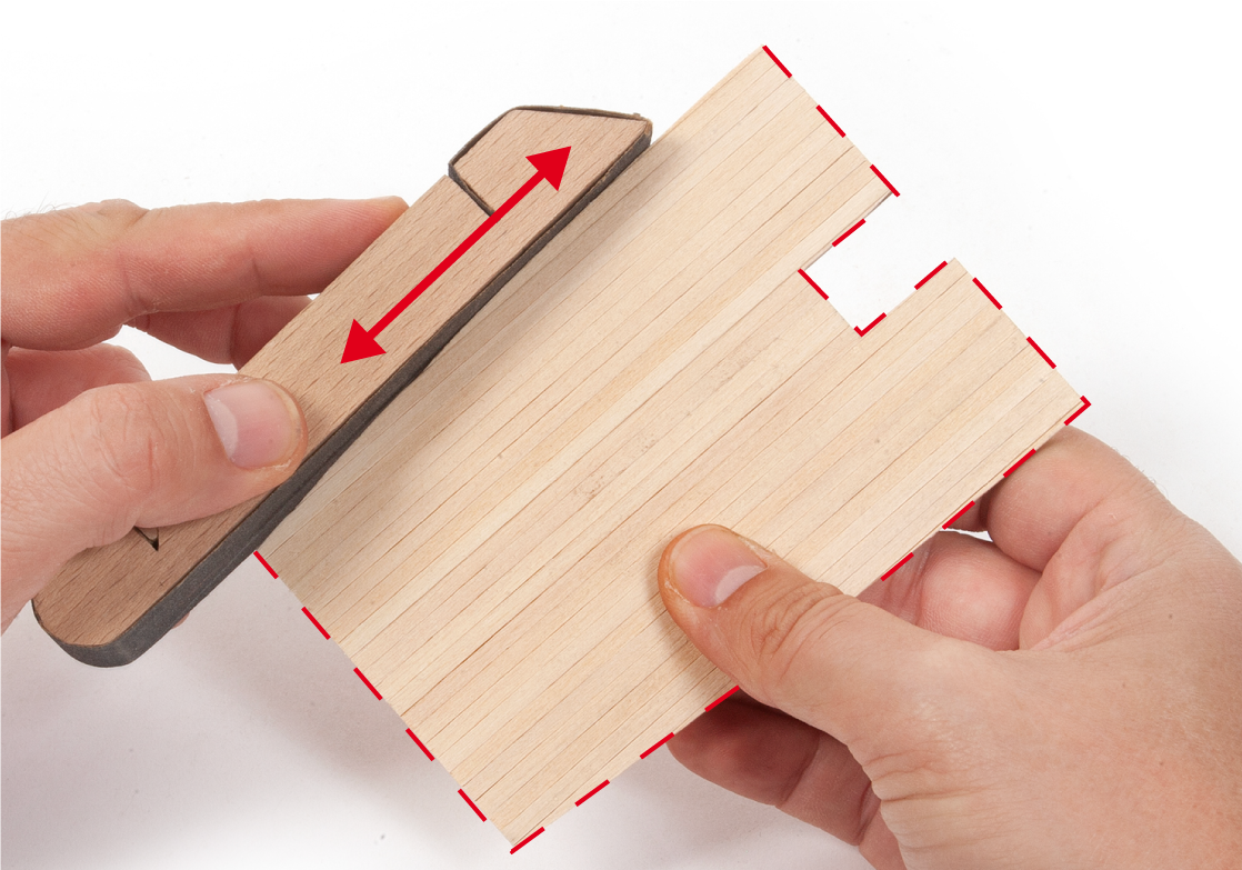
Sand the edges of the roof with a sanding block.
Step 9
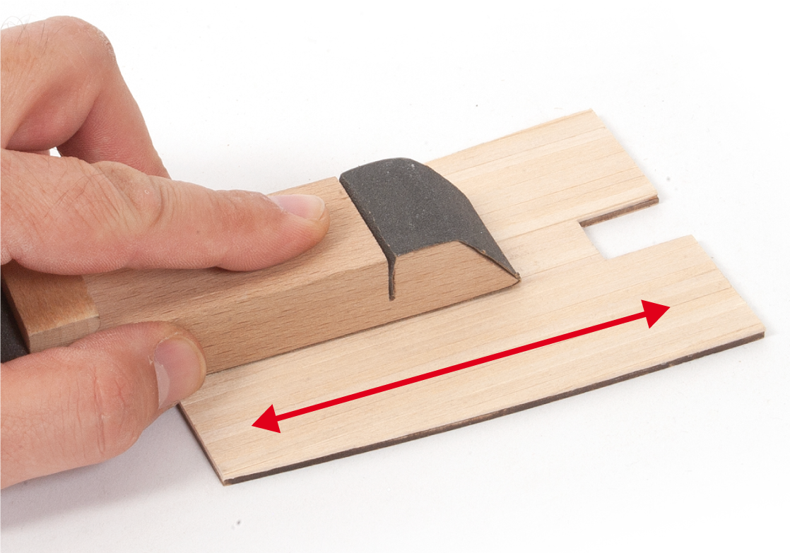
Sand the roof planking to remove any unevenness.
Step 10
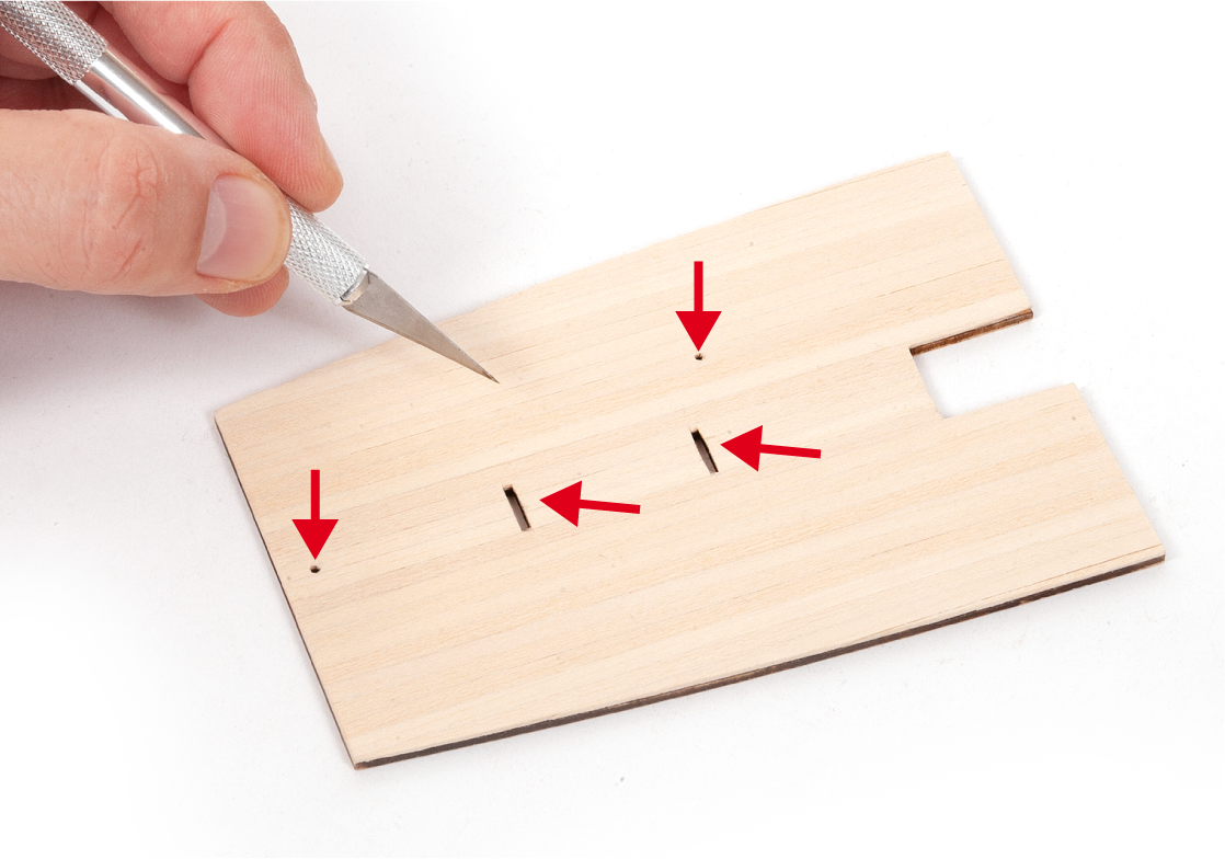
Cut out the slots and pierce the holes through the roof planking.
Step 11
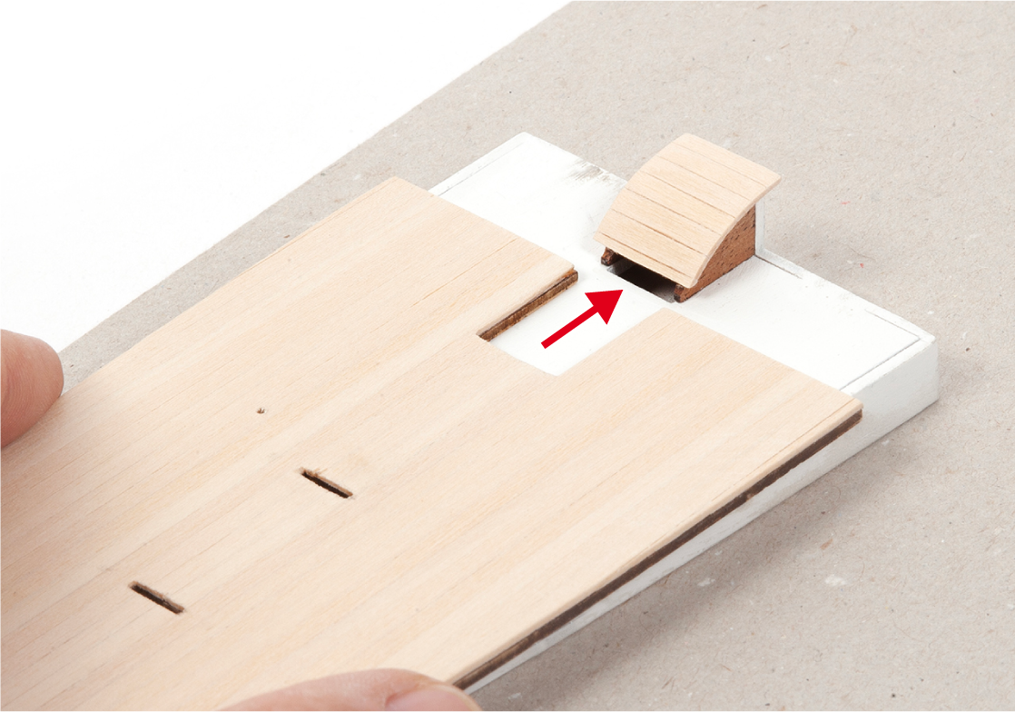
Adjust the parts if needed so that the roof sits correctly onto the poop deckhouse. Do not glue.
Step 12
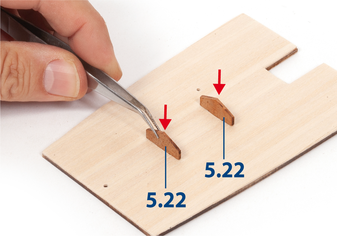
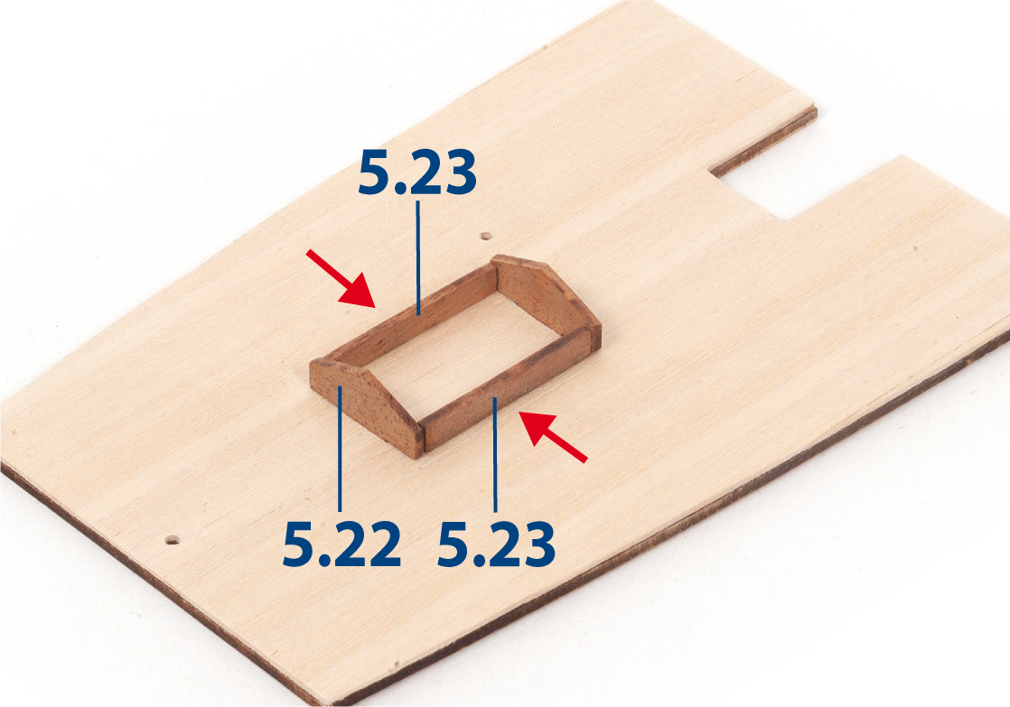
Insert parts 5.22. Do not glue.
Step 13
Glue parts 5.23 to parts 5.22. Do not glue this assembly to the roof.
Step 14
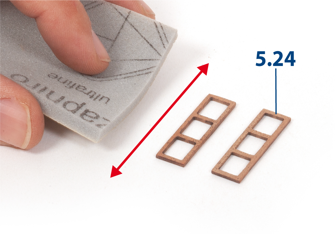
Sand parts 5.24 with a fine-grit sanding sponge.
Step 15
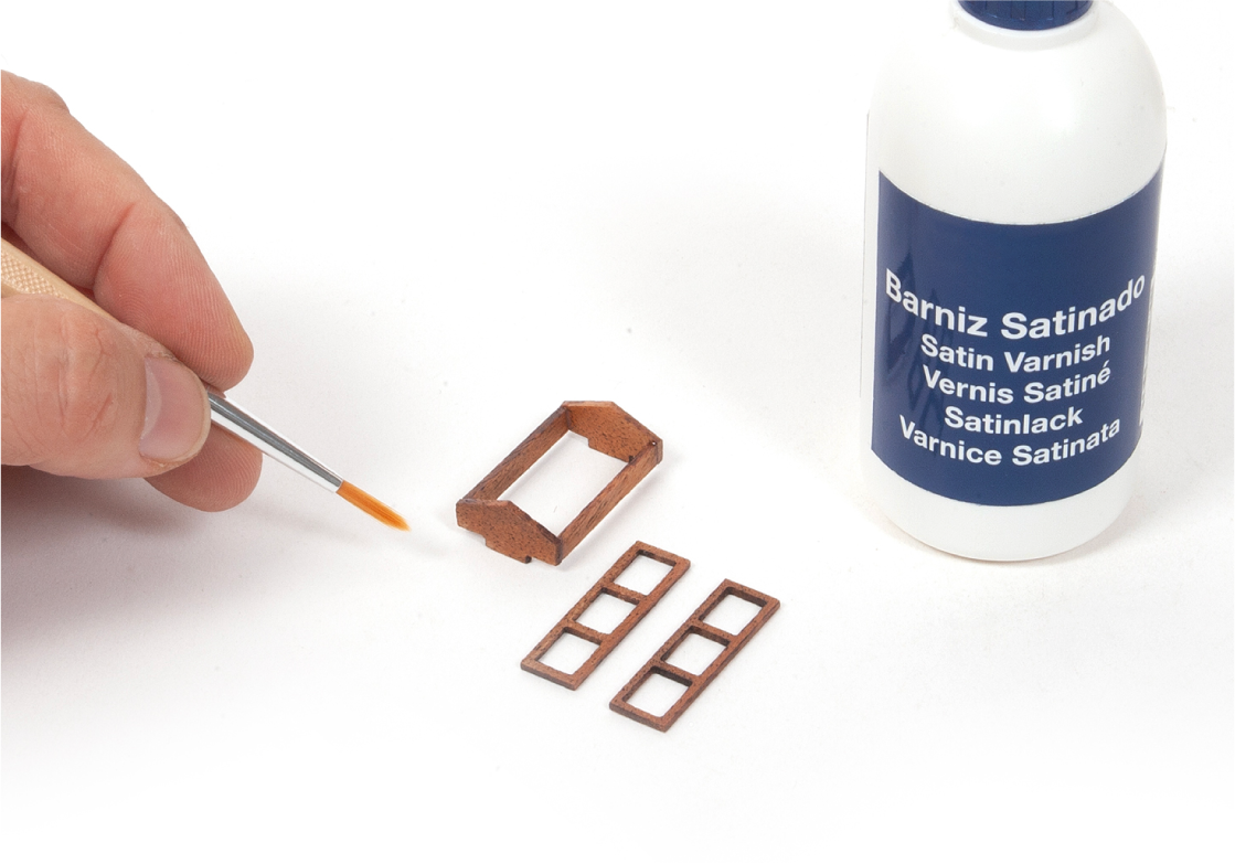
Varnish the parts shown.
Step 16
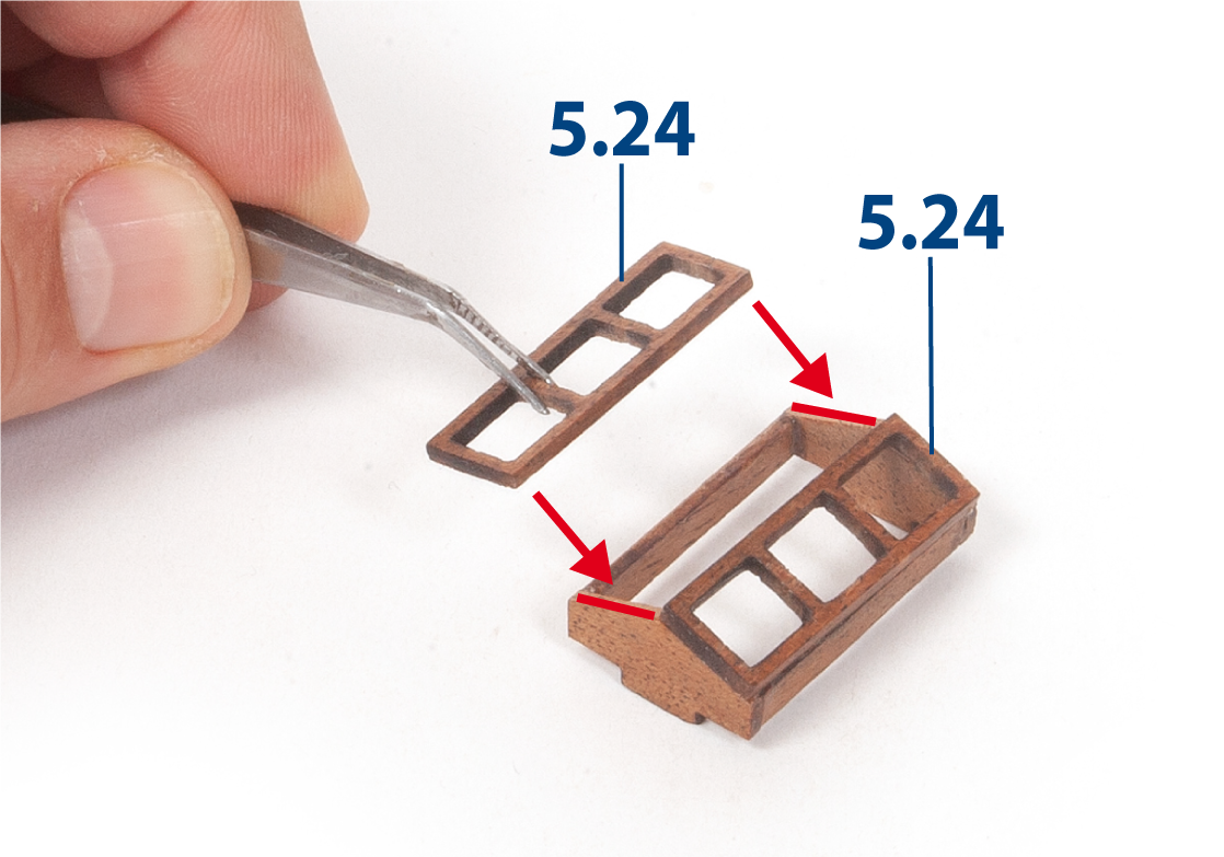
Glue both parts 5.24 to the assembly.
Step 1
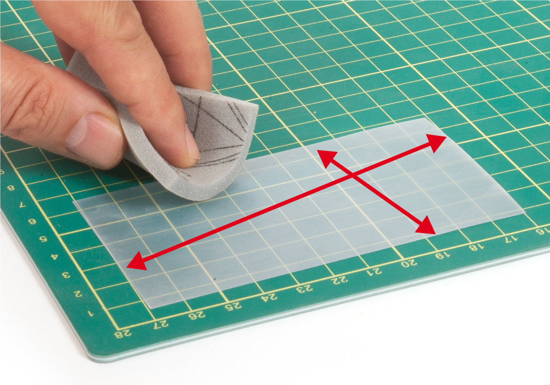
Sand a sheet of acetate to give it a frosted appearance.
Step 2
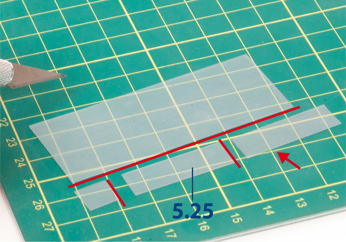
Cut two acetate parts 5.25 (8 x 28 mm) to size.
Step 3
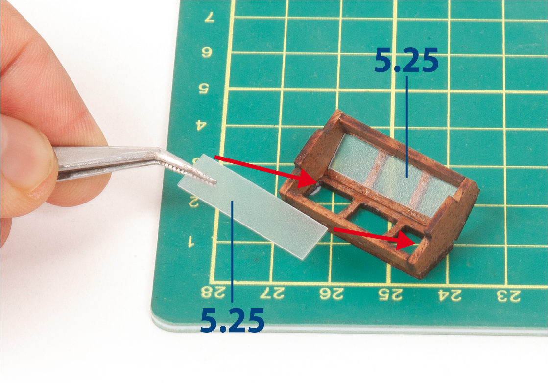
Glue both parts 5.25 to the inside faces of the skylight frames.
Step 4
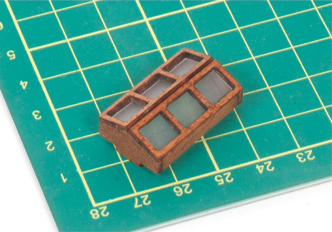
This image shows the finished skylight.
Step 5
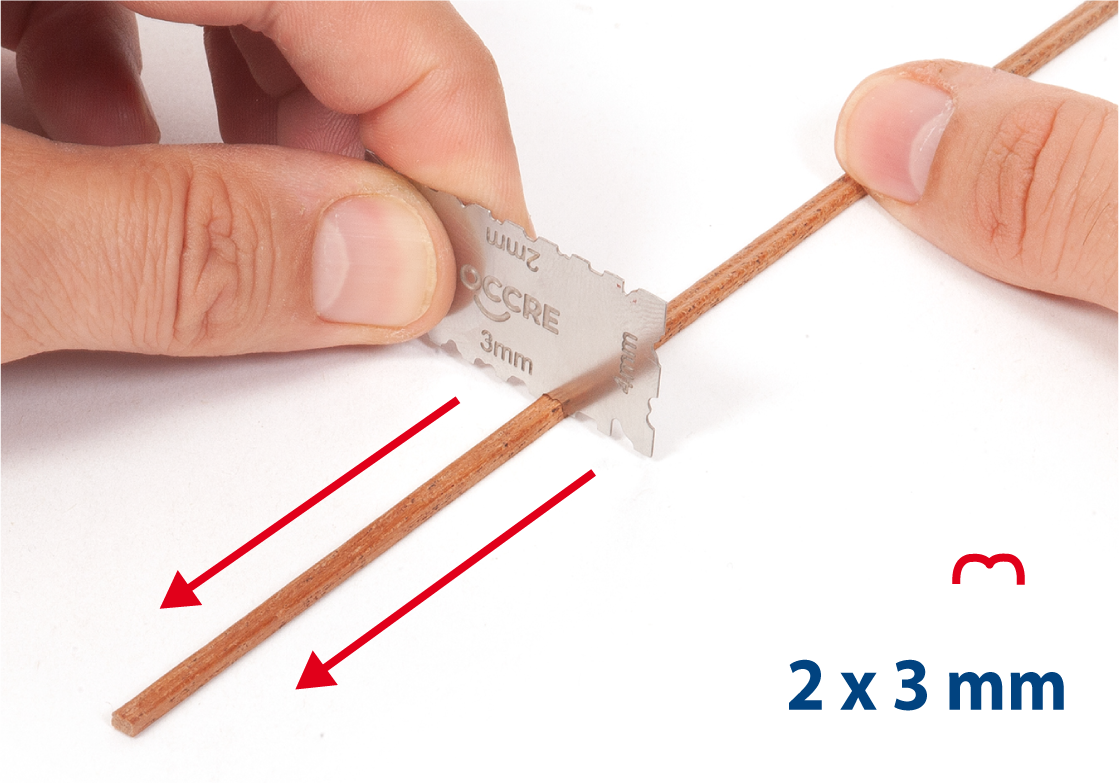
Use a grooving tool on a 2 x 3 mm mahogany strip, as shown.
Step 6
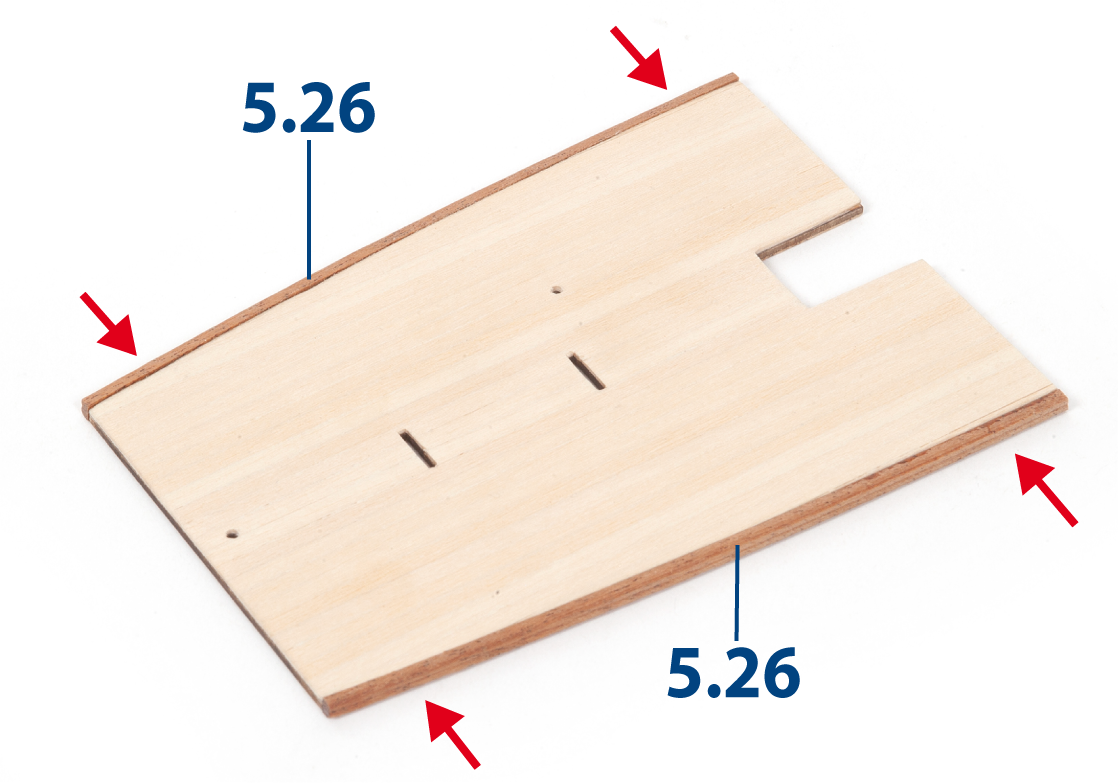
Cut the strip to length to create parts 5.26 (2 x 3 x 118 mm). Glue parts 5.26 to the roof, as shown.
Step 7
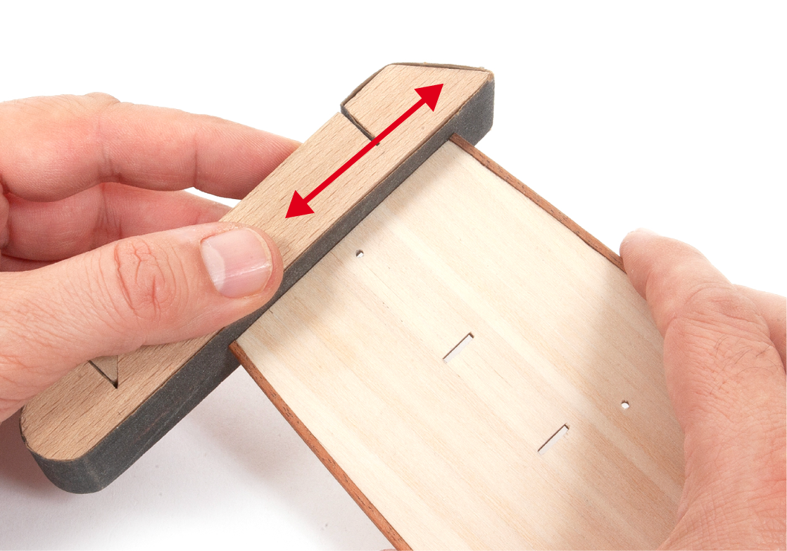
Sand the ends of parts 5.26 using a sanding block.
Step 8
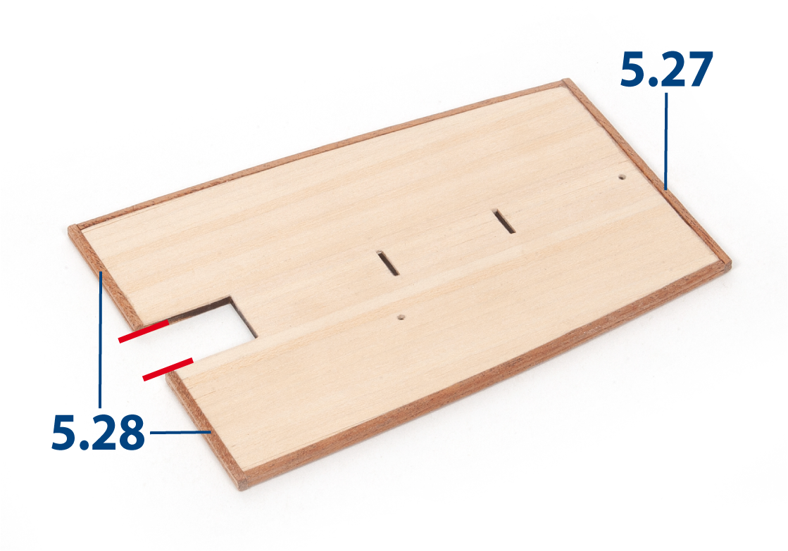
Cut additional grooved strips to length to create parts 5.27 (2 x 3 x 69 mm) and 5.28 (2 x 3 x 35 mm). Glue part 5.27 and both parts 5.28 to the roof, as shown. Varnish the roof.
Step 9
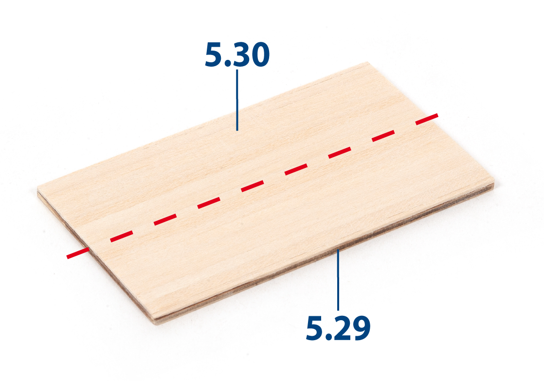
Glue parts 5.30 (1 x 3 x 82 mm lime wood) to part 5.29 to create the planking of the aft deckhouse roof.
Step 10
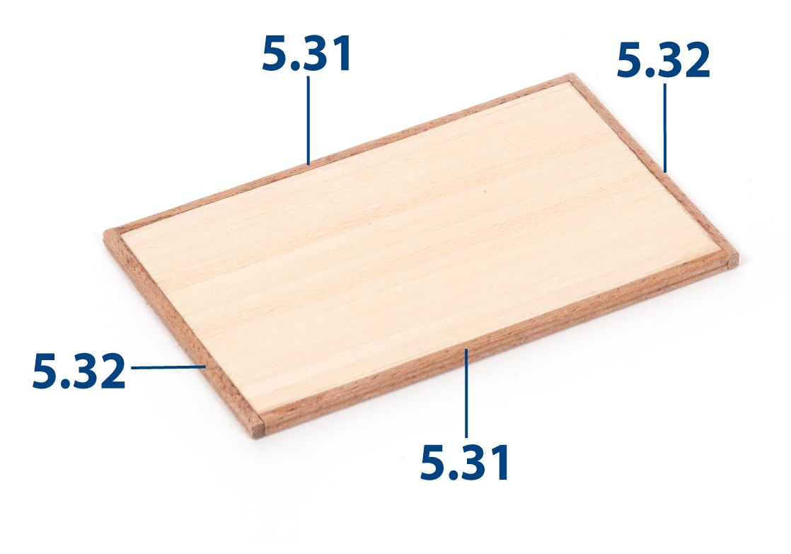
Make parts 5.31 (2 x 3 x 82 mm) and 5.32 (2 x 3 x 49 mm) from the grooved strip and glue them in place to frame the aft deckhouse roof.
Step 11
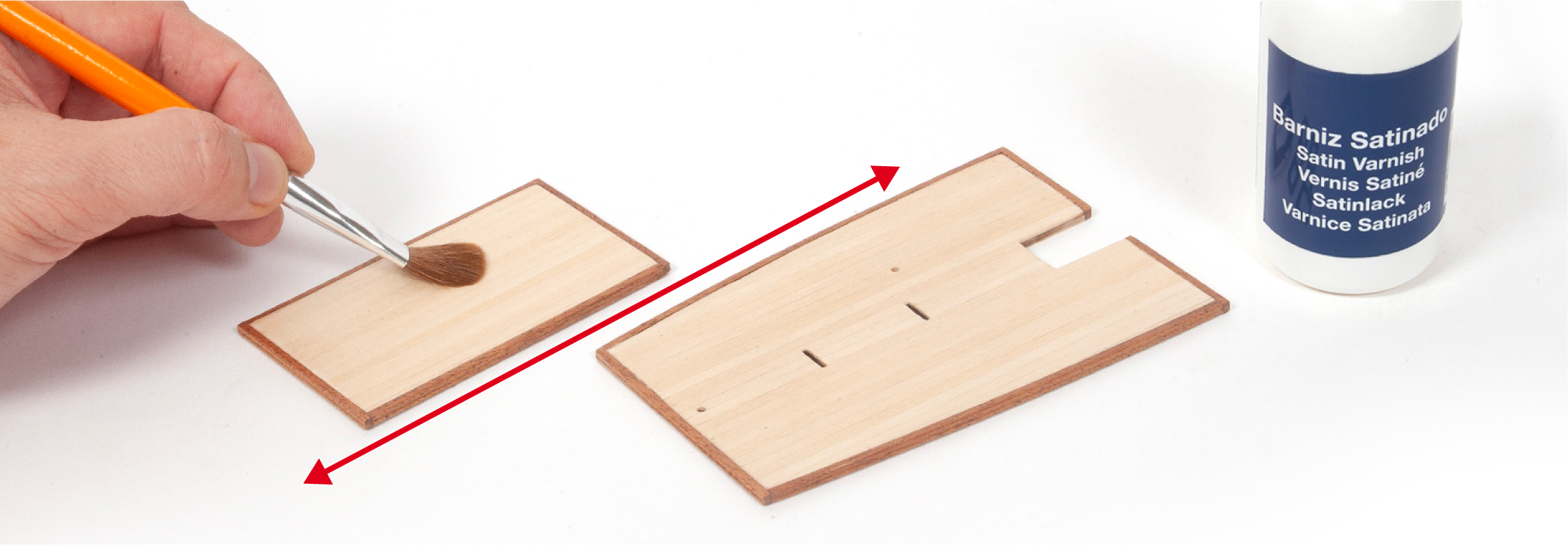
Varnish the aft deckhouse roof and the poop deckhouse roof.
Step 12
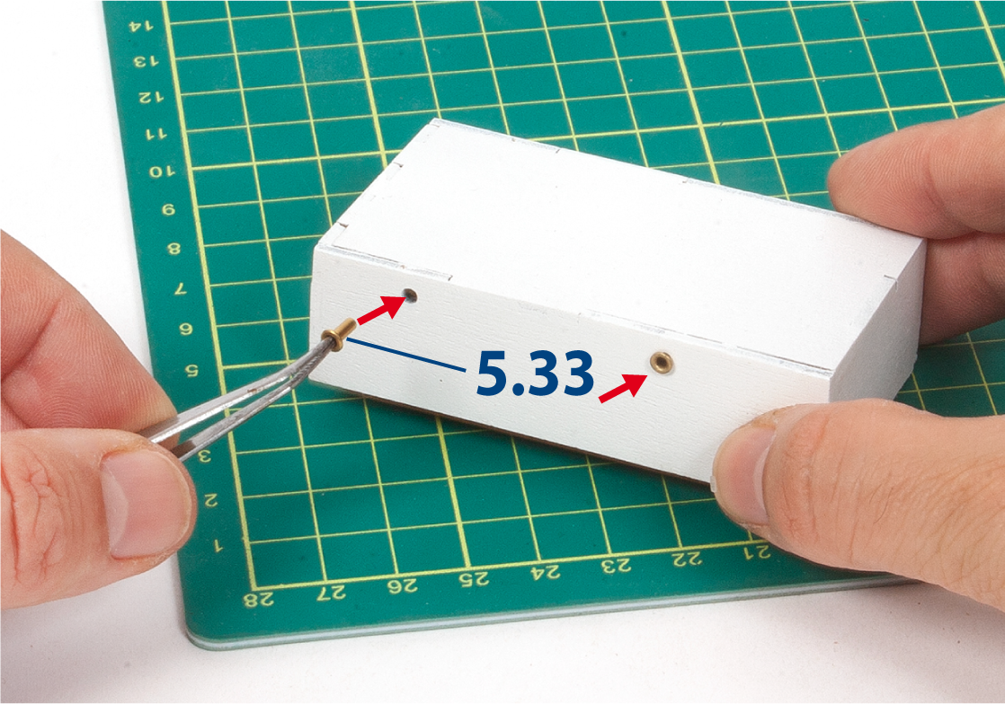
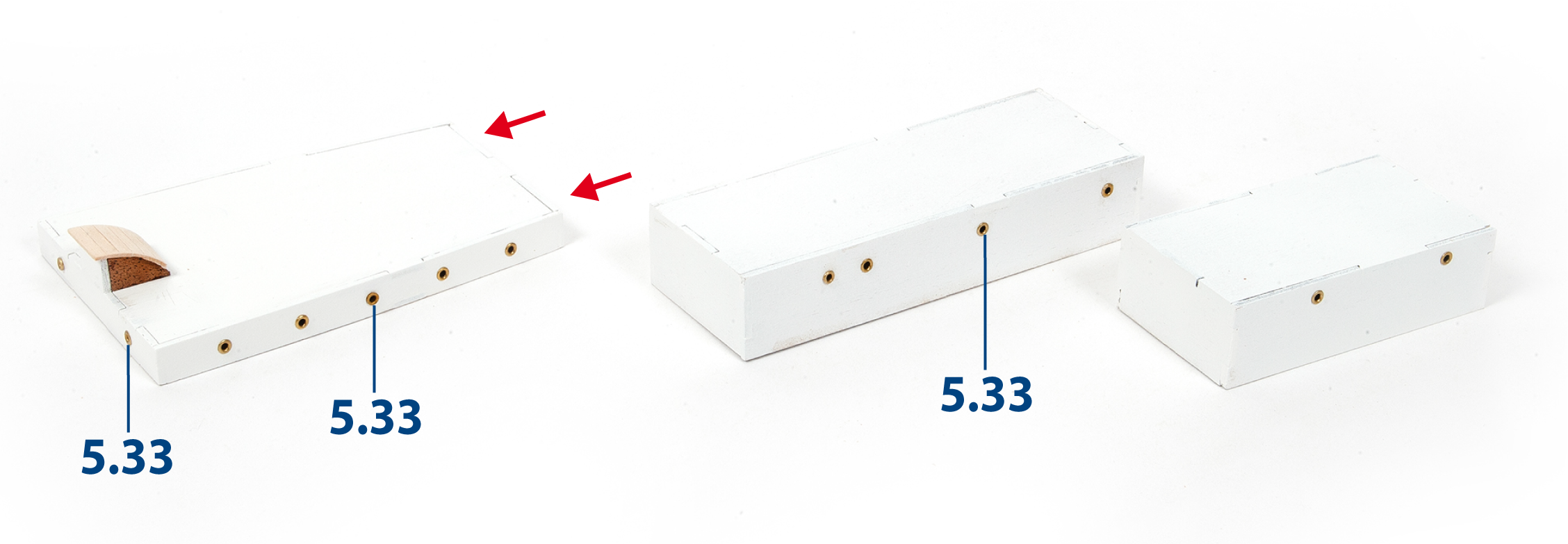
Glue rivets 5.33 into the holes of the aft deckhouse.
Step 13
Repeat for the remaining deckhouses.
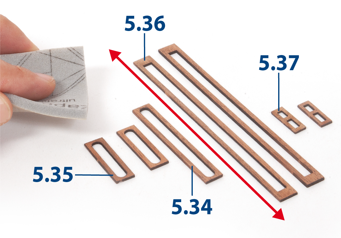
Step 1
Sand the parts shown in the image with a fine-grit sanding sponge.
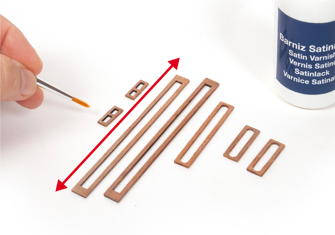
Step 2
Varnish these parts.
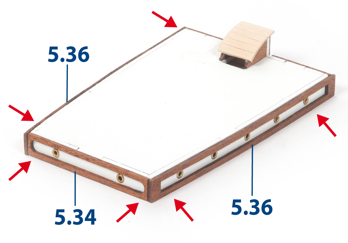
Step 3
Glue part 5.34 and both parts 5.36 to the poop deckhouse.
Step 4
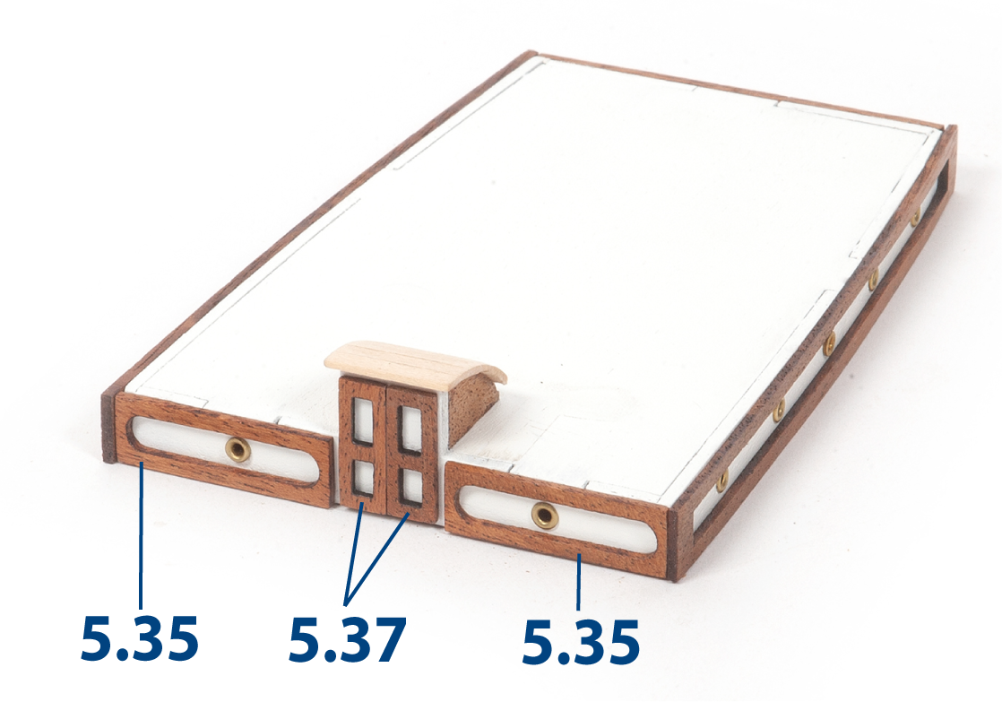
Glue both parts 5.35 and both parts 5.37, as shown.
Step 5
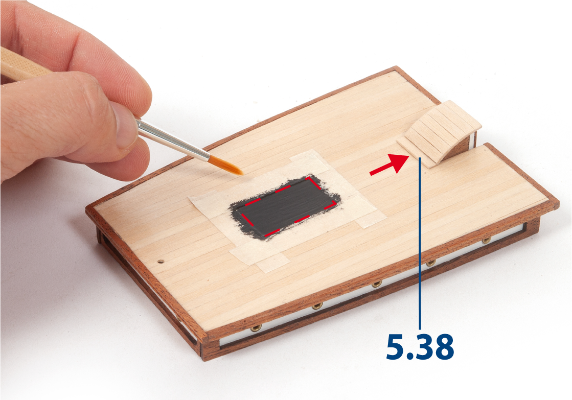
Glue the roof onto the poop deckhouse. Then add part 5.38 (1 x 3 x 17 mm lime wood) and varnish the assembly.
Mark an outline for the skylight, then paint the area where the skylight will sit black, keeping the paint within the marked area.
Step 6
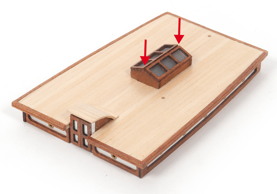
Glue the skylight onto the roof. Set the poop deckhouse aside.
Step 7
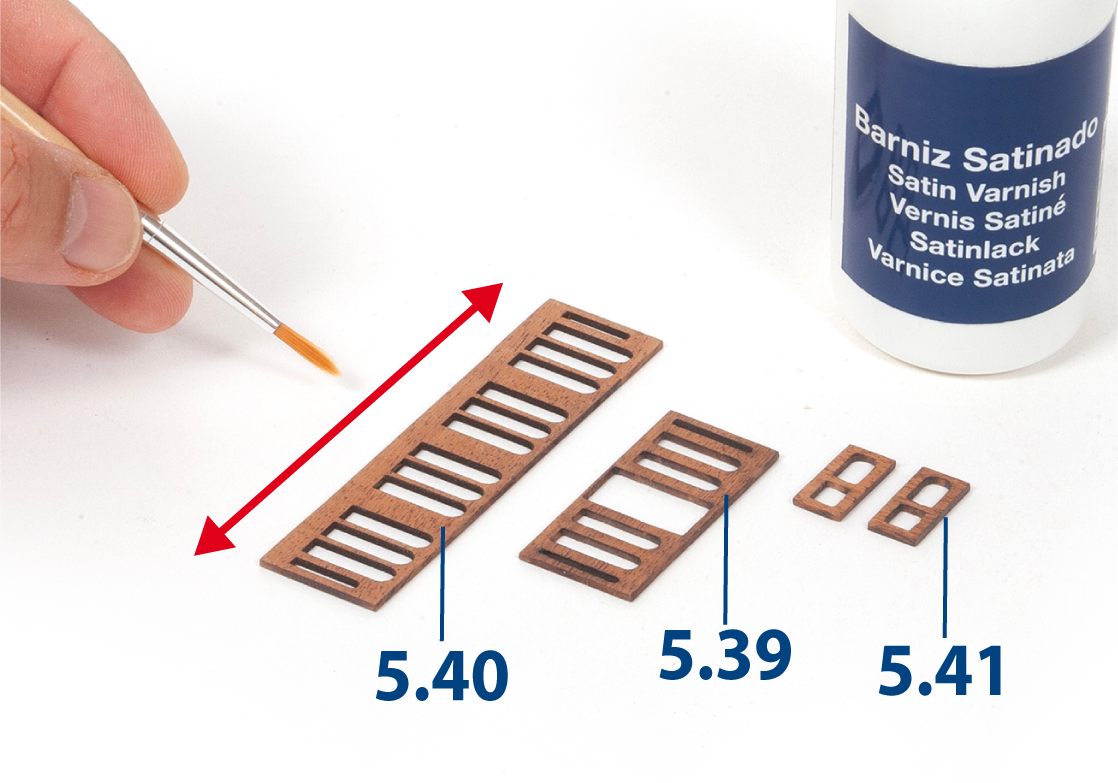
Sand parts 5.39 to 5.41 and apply varnish.
Step 8
Glue parts 5.39 to 5.41 to one side of the aft deckhouse.
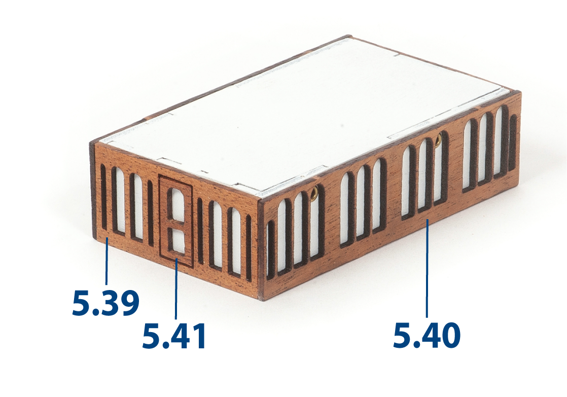
Step 9
Glue parts 5.39 to 5.41 to the opposite sides of the aft deckhouse.
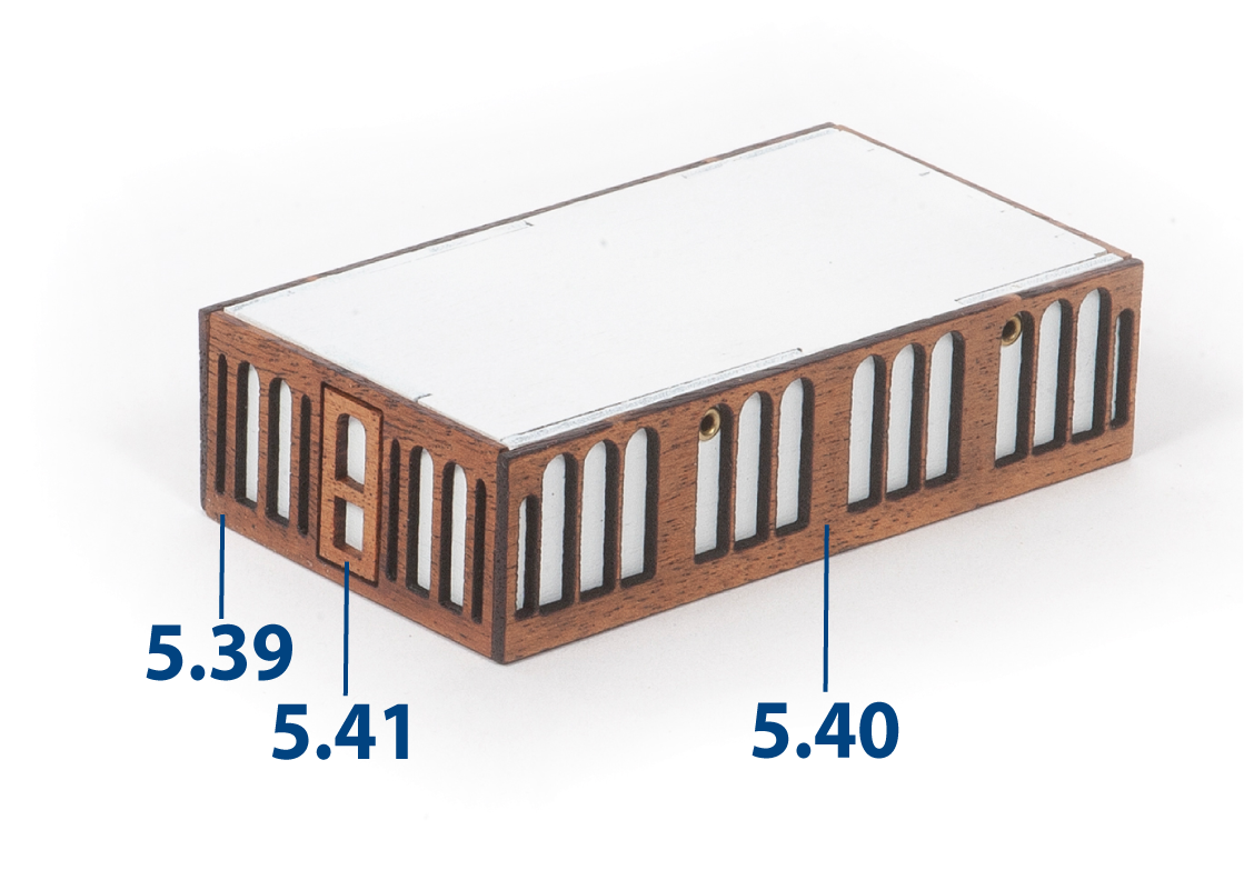
Step 10
Glue the roof onto the aft deckhouse and set the assembly aside.
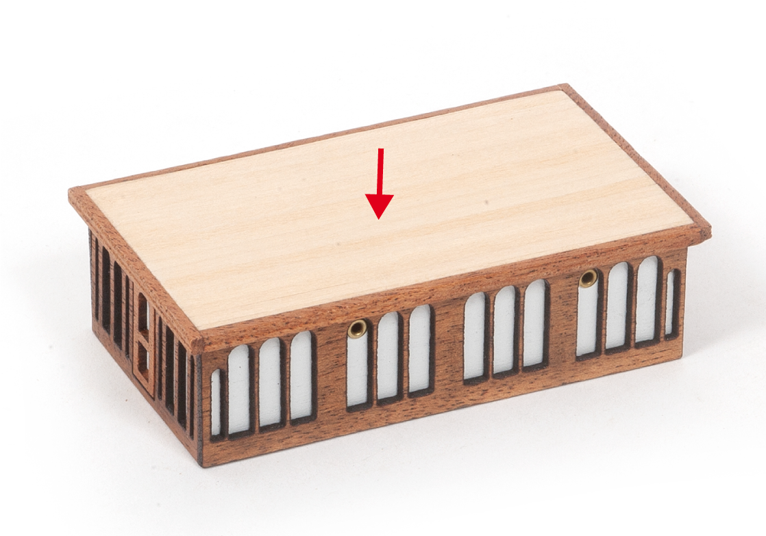
Step 11
Glue parts 5.43 to parts 5.42, leaving a 13 mm gap between the two parts 5.43, as shown. Refer to the image of step 12 to check the fit.
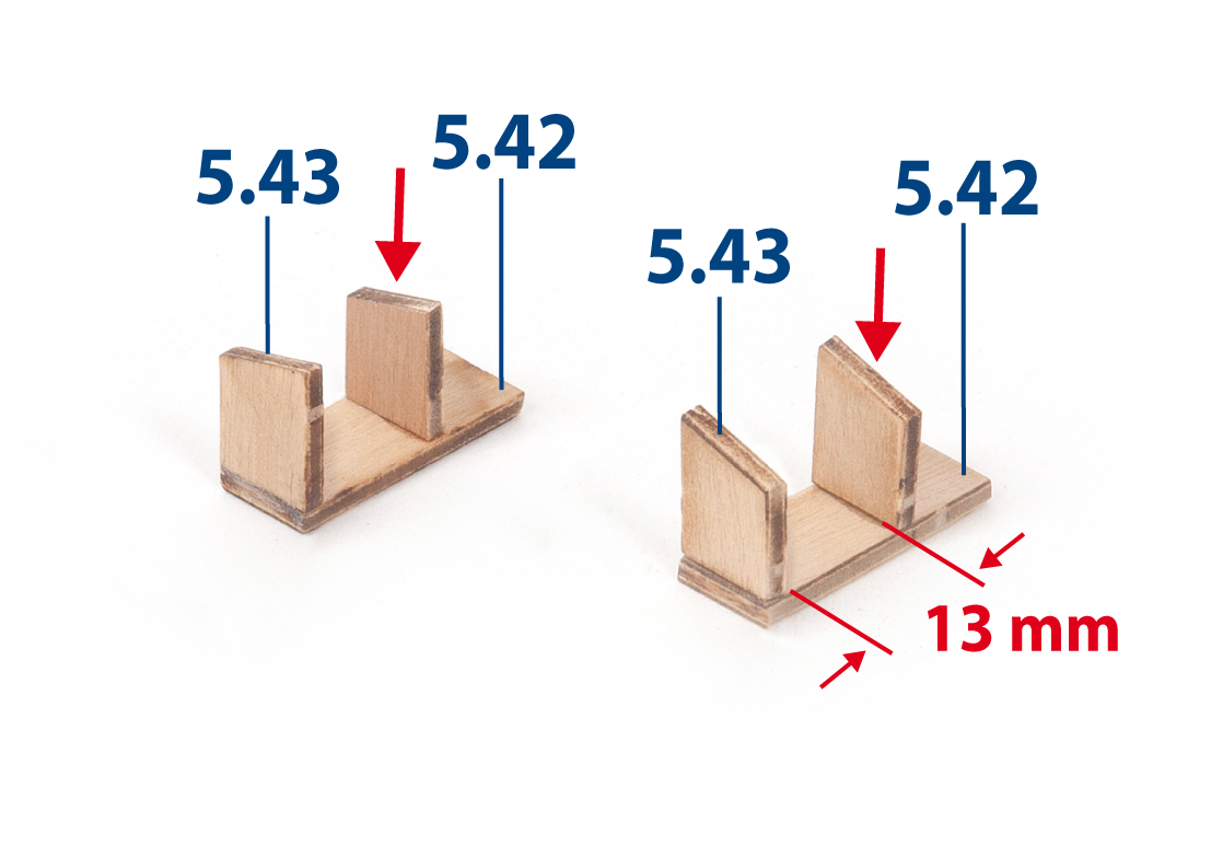
Step 12
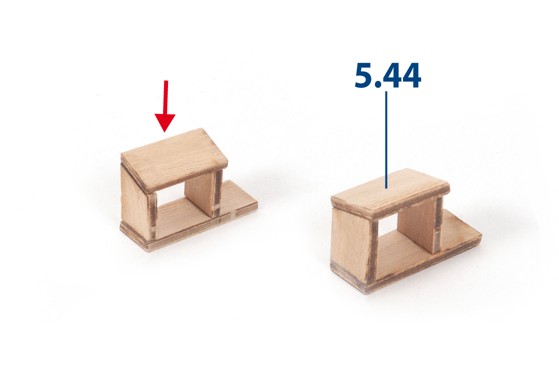
Glue parts 5.44 on top.
Step 13
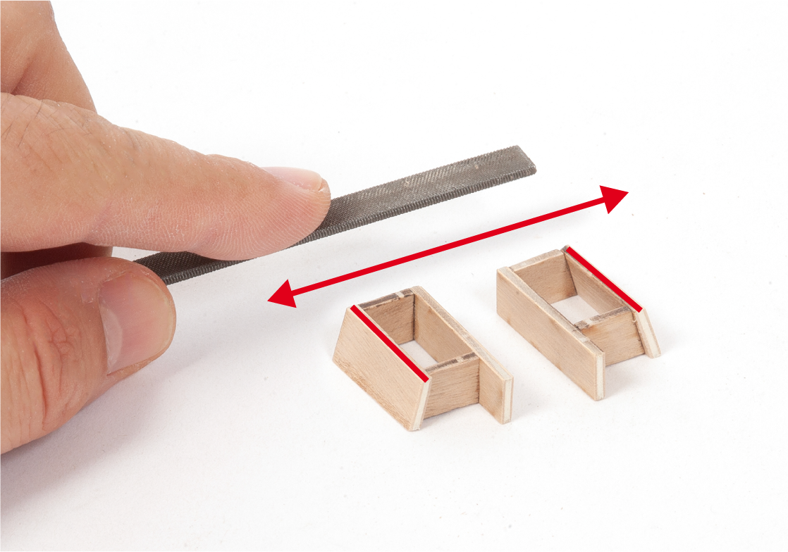
Sand the completed assemblies so that their sides are flat.
Step 14
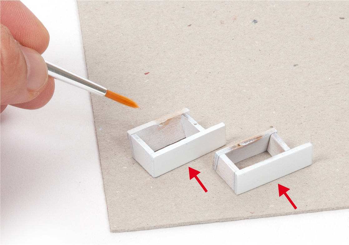
Paint the assemblies white.
Step 15
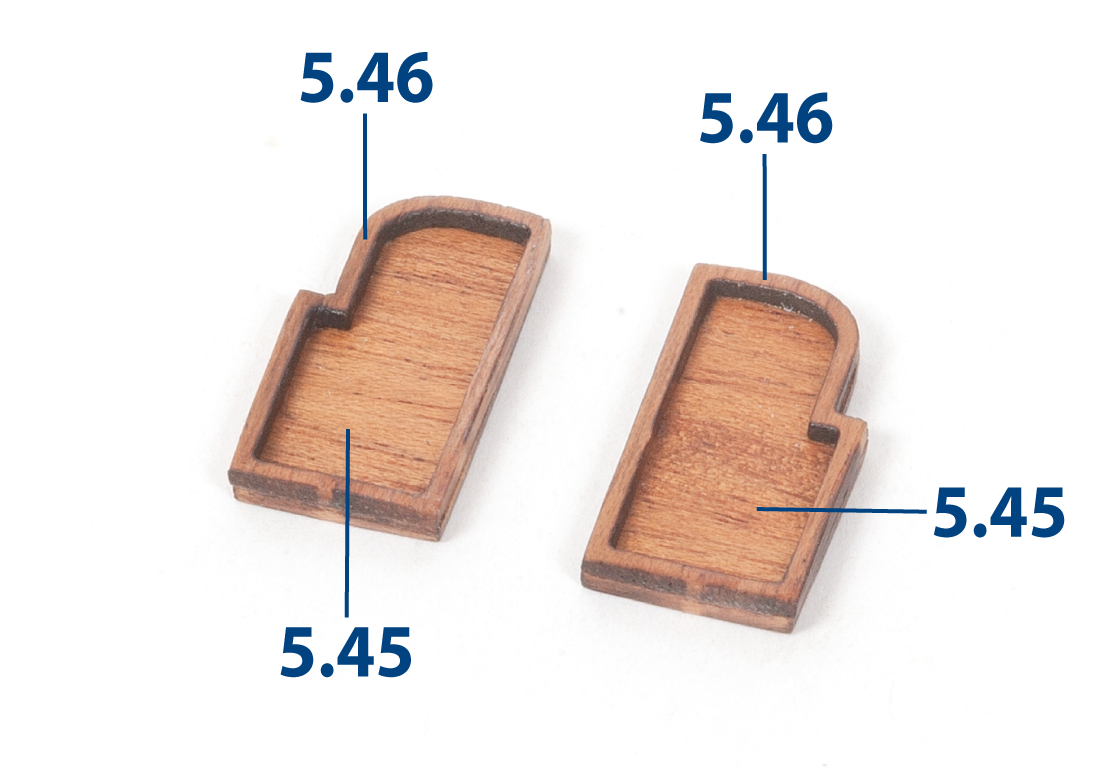
Sand parts 5.45 and 5.46. Glue them together.
Step 16
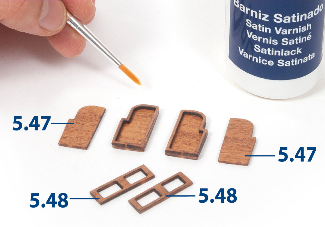
Sand the parts shown, then apply varnish.
Step 17
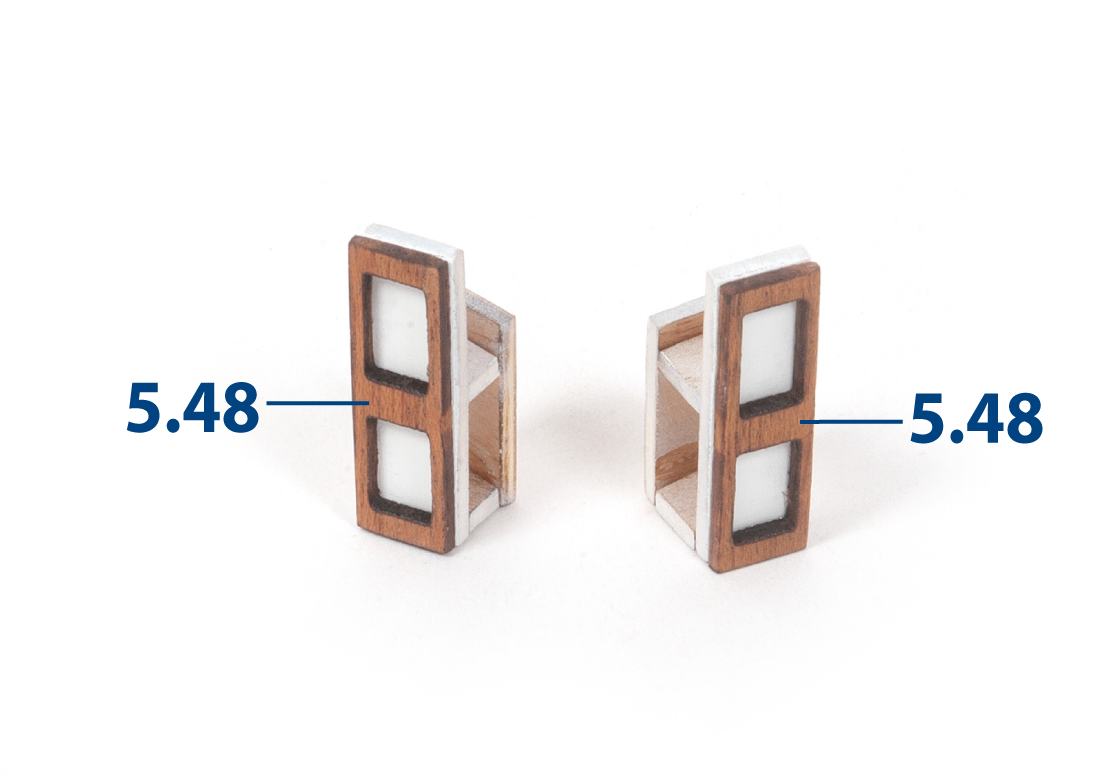
Glue parts 5.48 to the assemblies.
Step 18
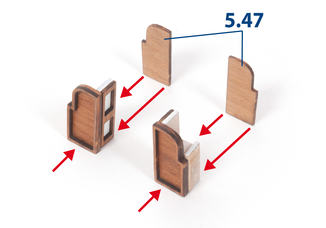
Glue the parts together as shown in the image.
Step 19
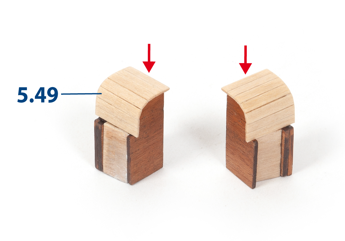
Cover the tops of both assemblies with parts 5.49 (1 x 3 x 13 mm lime wood).
Step 20
Trim and sand the covering on both assemblies, then varnish them.
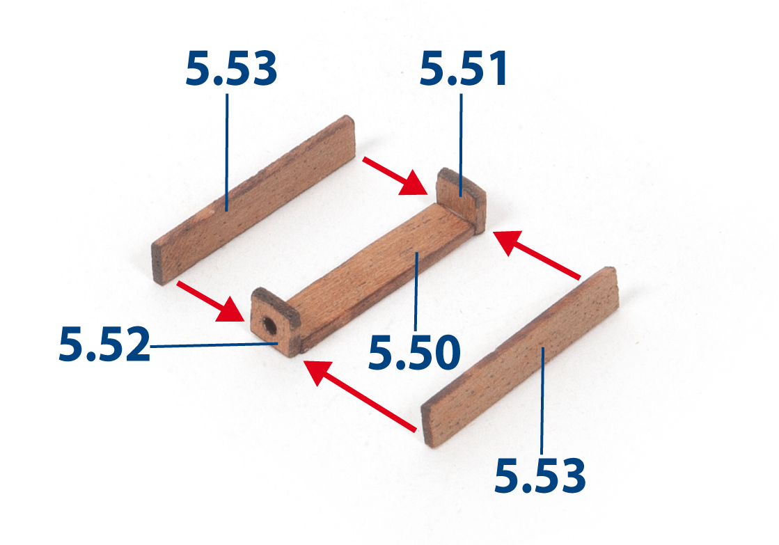
Step 1
Glue the parts shown in the image.
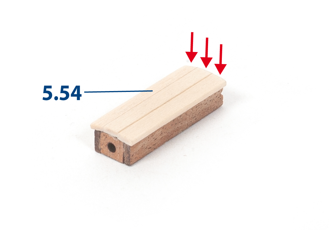
Step 2
Glue parts 5.54 (1 x 3 x 26 mm lime wood) on top. Then sand their ends flush.
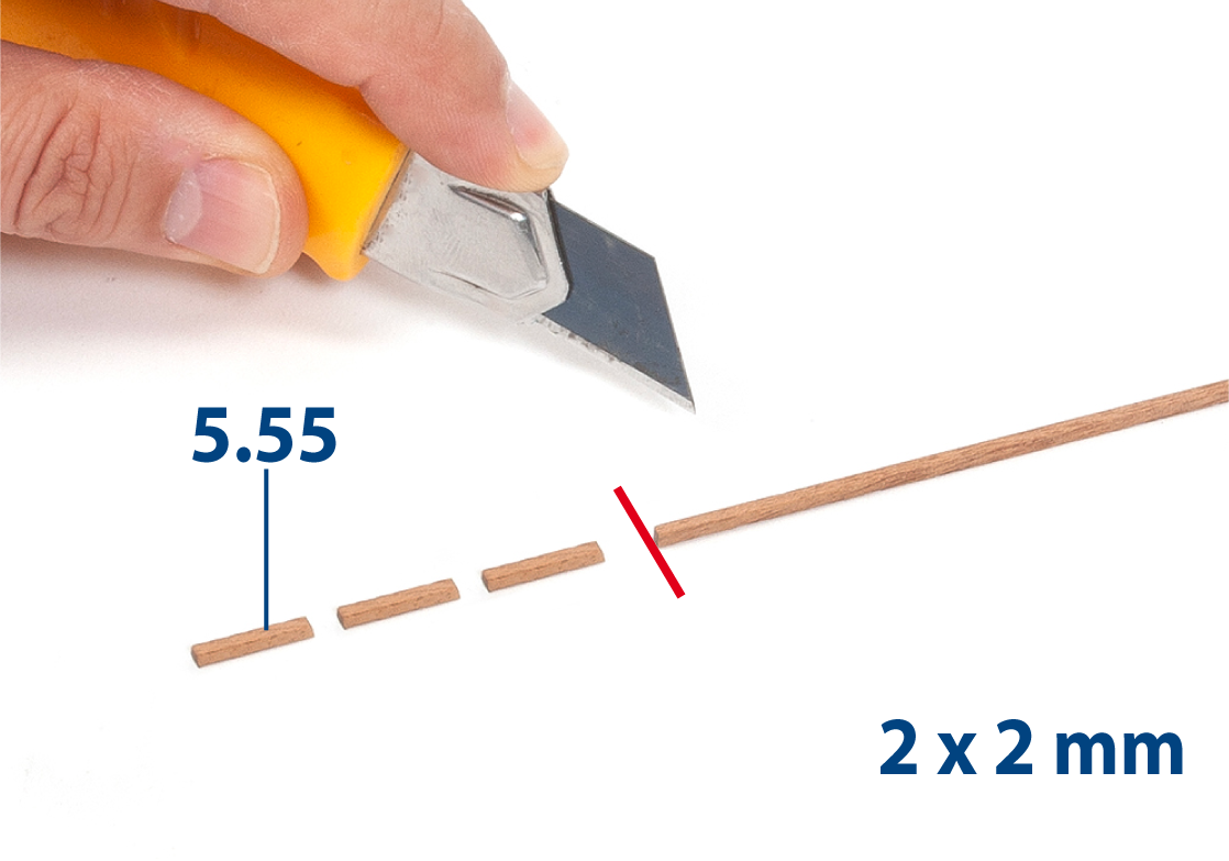
Step 3
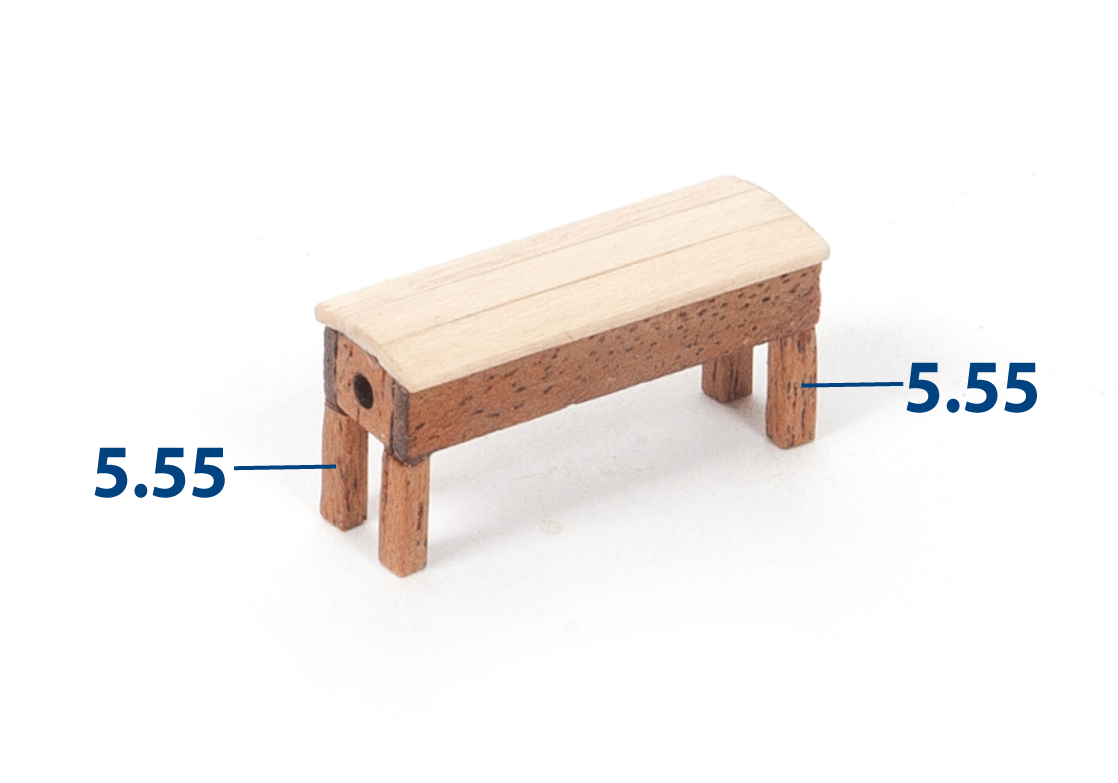
Sand a 2 x 2 mm mahogany strip. Then cut parts 5.55 (2 x 2 x 9 mm) to length.
Step 4
Glue parts 5.55. Varnish the steering gear housing assembly.
Step 5
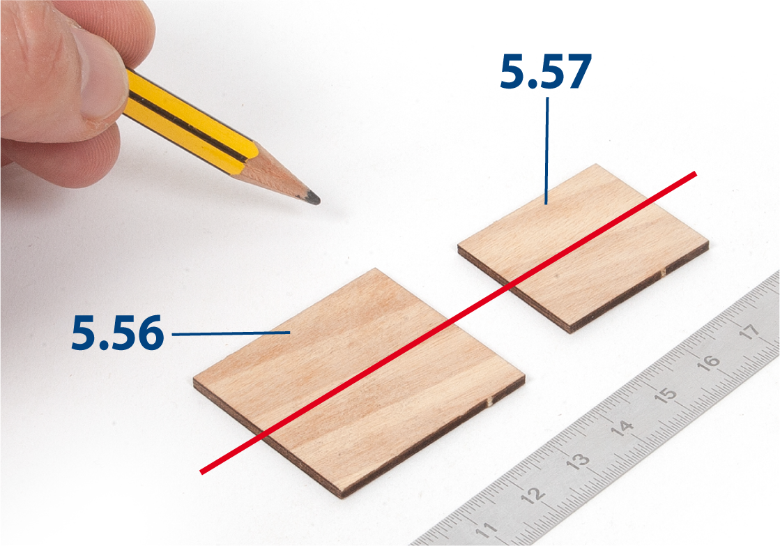
Draw a line down the centre of parts 5.56 and 5.57.
Step 6
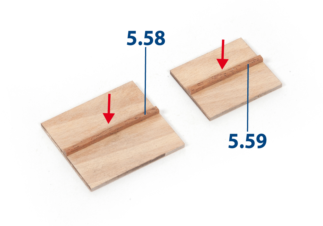
Cut parts 5.58 (2 x 2 x 37 mm) and 5.59 (2 x 2 x 31 mm) to length, then glue them along the drawn line.
Step 7
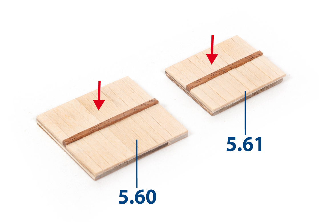
Cut parts 5.60 (1 x 3 x 17 mm lime wood) and 5.61 (1 x 3 x 13 mm lime wood) and glue them in place, as shown.
Step 8
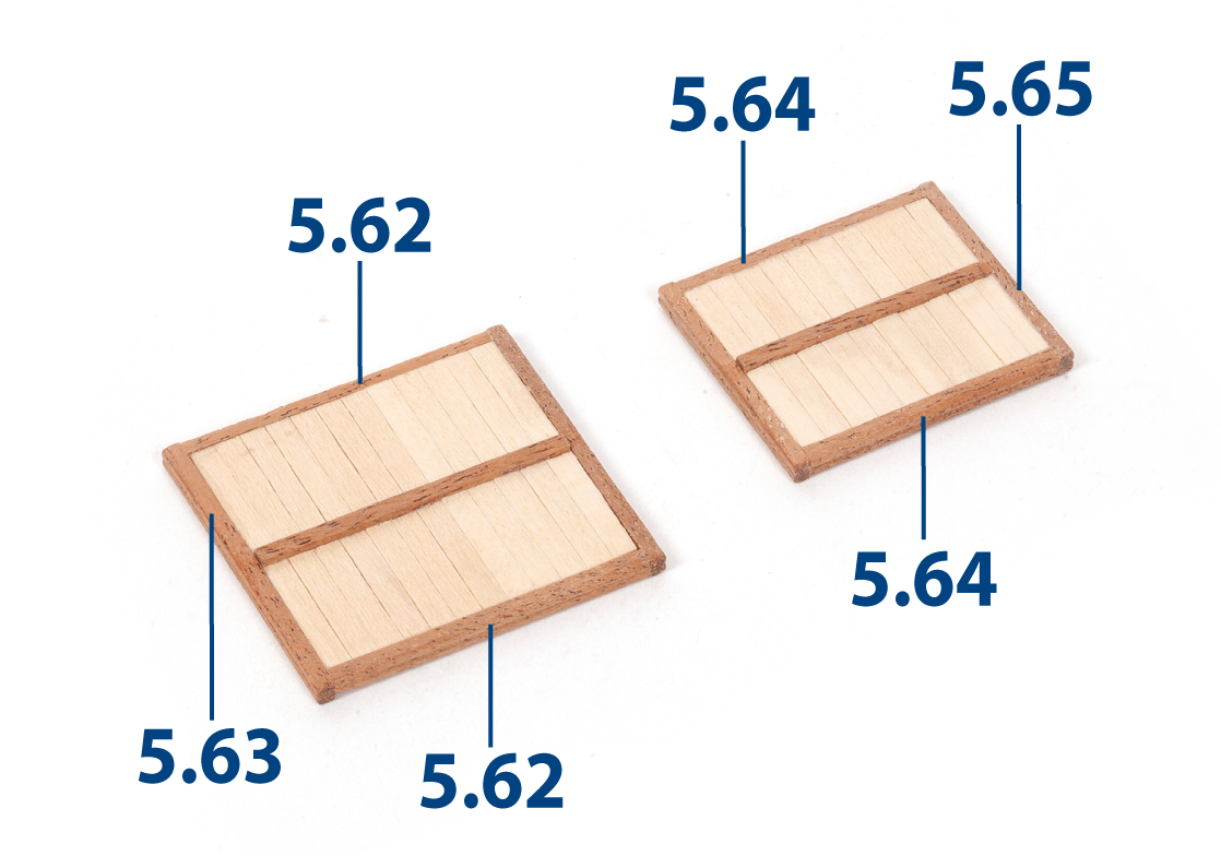
Cut grooved strips 5.62 to 5.65 to length and glue them in place.
| 5.62 | 2 x 2 x 37 mm |
| 5.63 | 2 x 2 x 39 mm |
| 5.64 | 2 x 2 x 31 mm |
| 5.65 | 2 x 2 x 31 mm |
Step 9
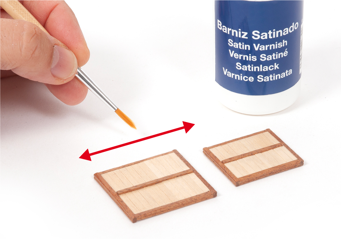
Sand both hatch assemblies, then apply varnish.
Step 10
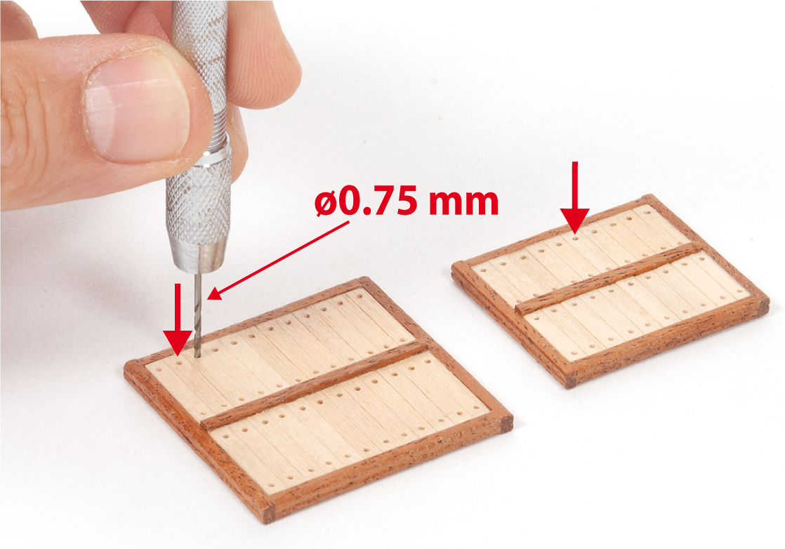
Drill a ø0.75 mm hole at the ends of each part, as shown.
Step 11
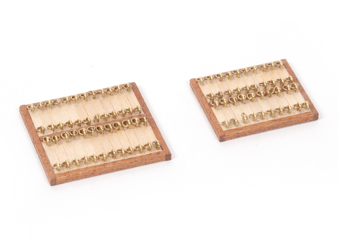
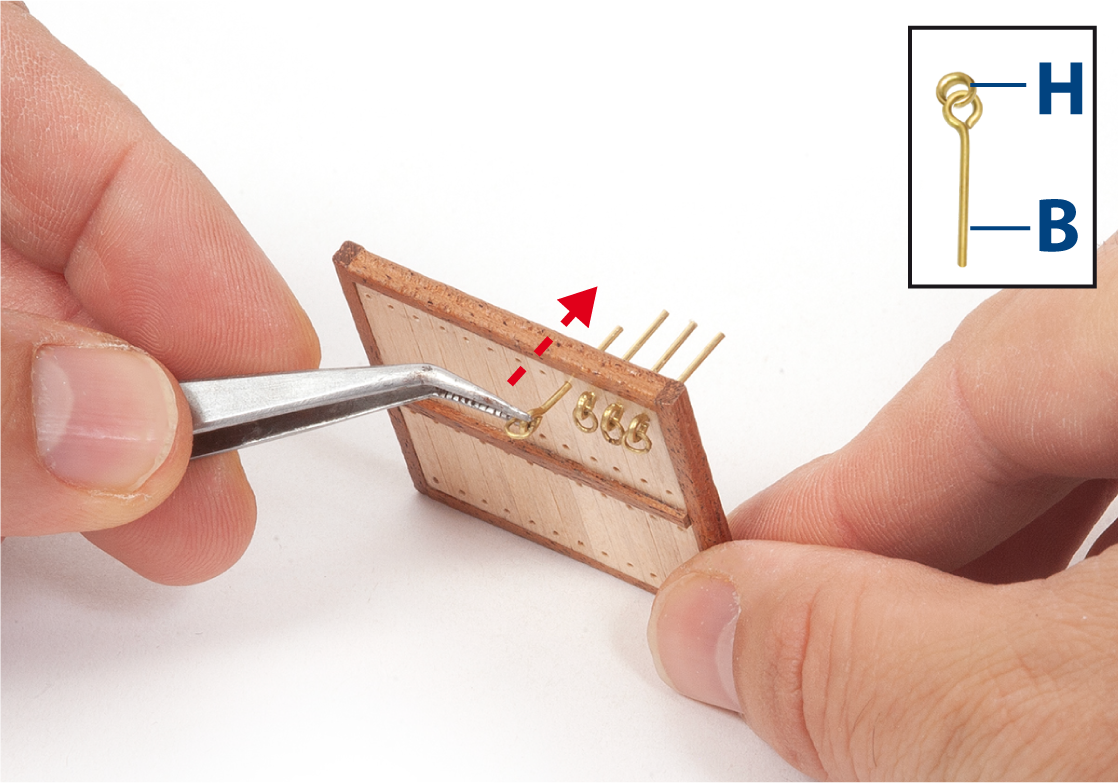
Attach one ring H to each eyebolt B. Glue each eyebolt into a drilled hole. There should be 88 eyebolts in total. Note the orientation shown in the following images.
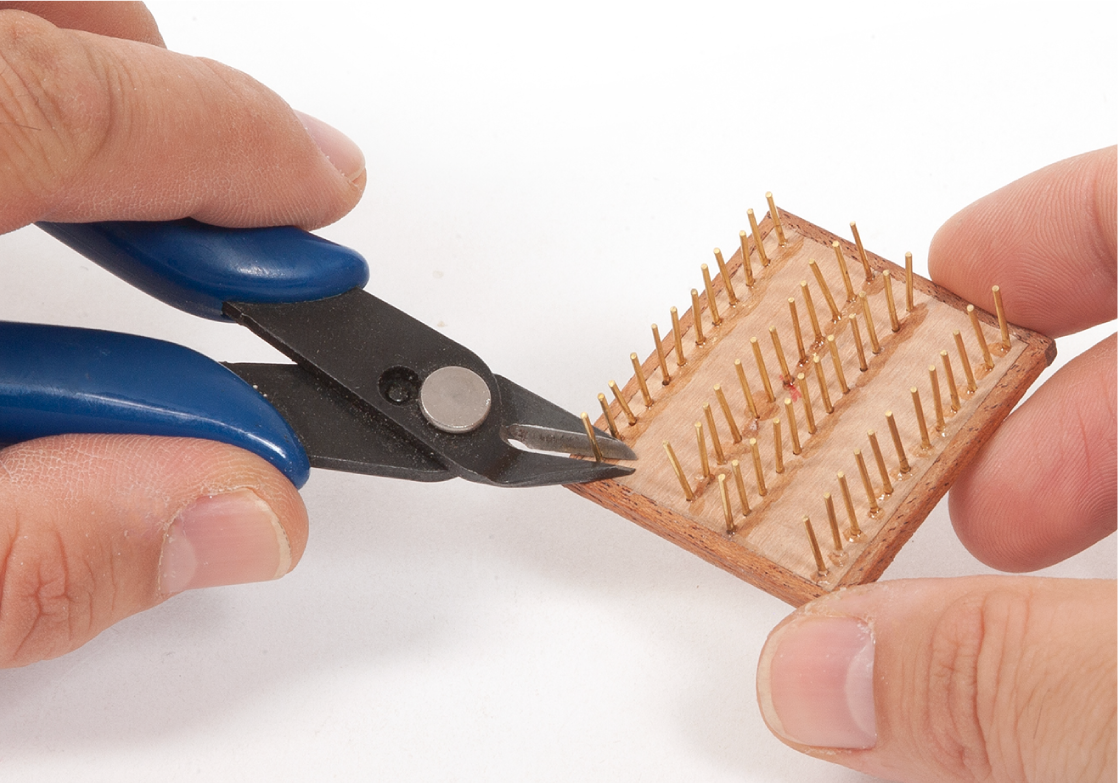
Step 12
Cut off the protruding ends of the eyebolts on the reverse side using pliers.
Step 13
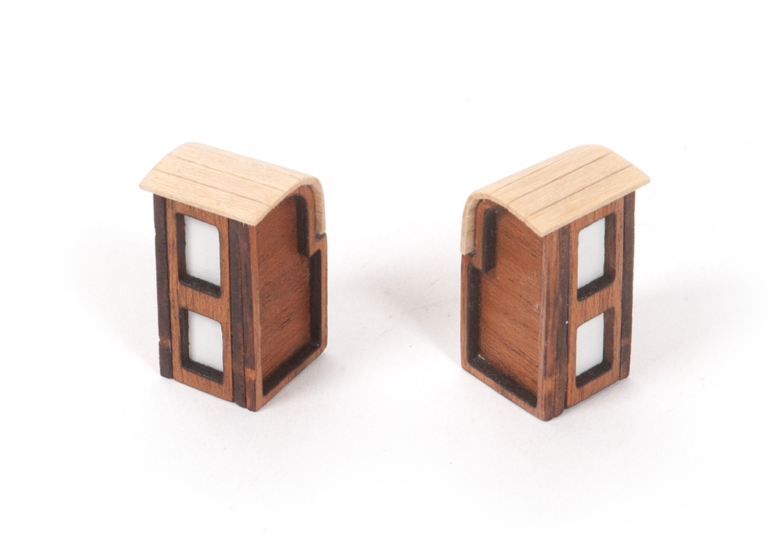
This image shows the two completed assemblies.