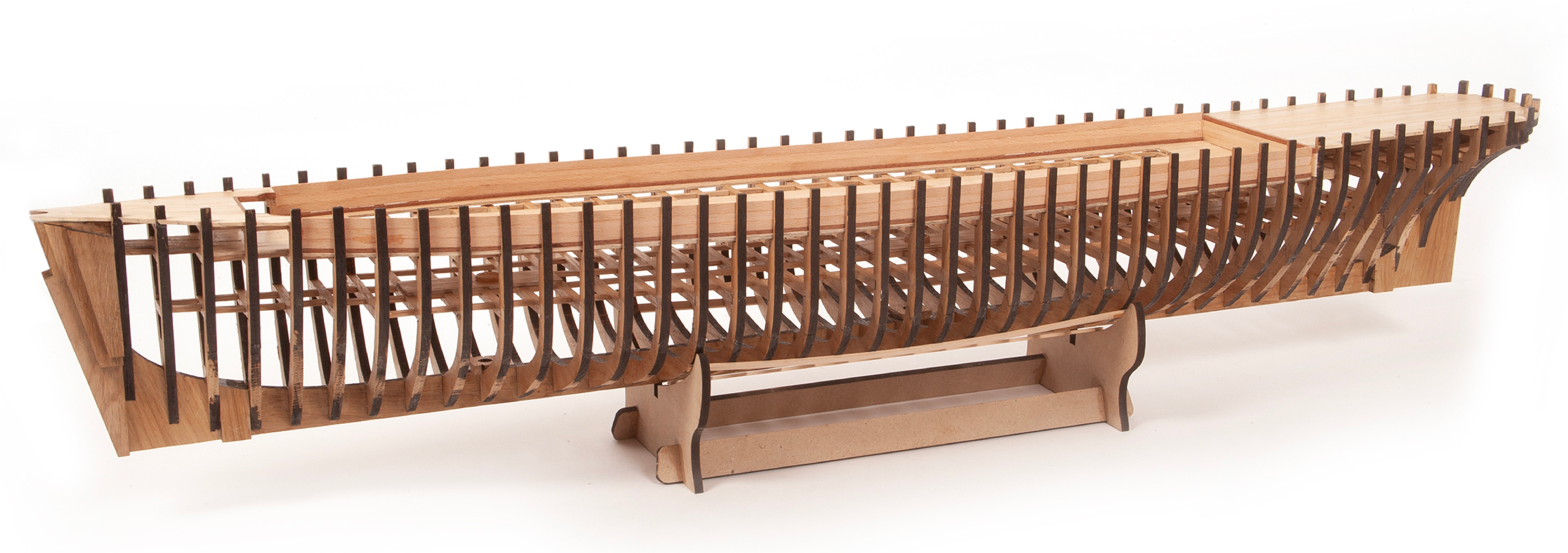
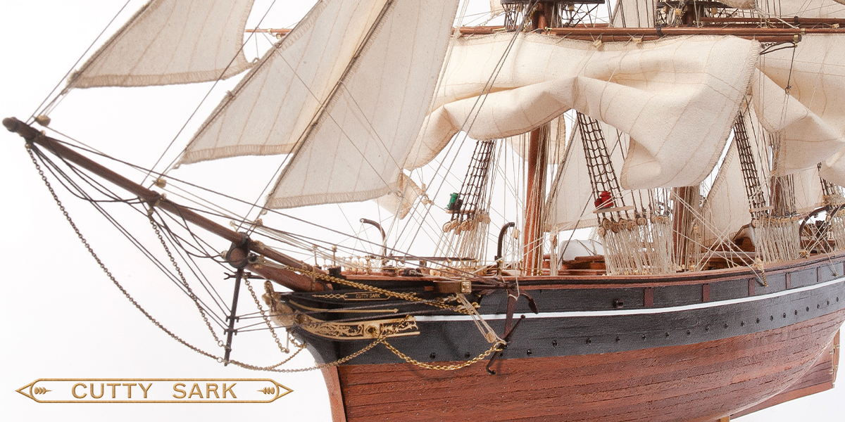
Pack 06
BUILD INSTRUCTIONS
Instructions for building your Cutty Sark model ship
Your model of the Cutty Sark is divided into 12 packs.
You will need to follow the step-by-step assembly photos, the plans and the explanatory texts below.
Please save the leftover materials from each pack for use when instructed to do so at a later stage of the assembly instructions.
The IP sheets displayed below are drawings of laser-cut parts and photo-etched brass parts and will serve as a guide for identification of some parts.
Use the PARTS REFERENCE table to help locate the parts.
The PL-00 templates (printed at 1/1 scale) will serve as a guide for building the frames.
Please check the list below to ensure you have all the tools required for building your wooden ship.
When removing a part, cut the ribs that join the part to the wooden plate with a cutter.
Remove the parts carefully so as not to break them.
Keep and store the parts in their frames. Only remove the parts you are working on in each step.
Extra support can be found on our forum.
PARTS LIST
| Material | Quantity | |
| Wooden Boards | ||
| 2002-16 | Wood | 1 |
| Wooden Strips | ||
| 1 x 3 x 600 mm | Lime wood | 20 |
| 2 x 5 x 600 mm | Lime wood | 20 |
| 1 x 5 x 600 mm | Lime wood | 10 |
| 2 x 5 x 600 mm | Mahogany | 60 |
| Rods | ||
| ø3 x 400 mm | Mahogany | 1 |
| Other | ||
| Brass wire (ø1.5 x 400 mm) | Brass | 1 |
| Bilge pump (6.37) | Brass | 1 |
| Pump wheel (6.36) | Brass | 2 |
| Pump structure (6.38) | Brass | 2 |
| Winch side (6.26) | Brass | 4 |
| Winch cog (6.27) | Brass | 2 |
| Small winch cog (6.28) | Brass | 4 |
| Winch handle (6.30) | Brass | 6 |
| Windlass (6.25) | Brass | 1 |
| Chimney (8.1) | Brass | 1 |
| Capstan (9.29) | Brass | 1 |
| Winch drum end (6.29) | Brass | 4 |
| Brass washer (6.31) | Brass | 4 |
| Display base (12.1) | Wood | 1 |
| Supports (12.2) | Brass | 2 |
| Paint | ||
| Dark red (30 ml) | Acrylic | 1 |
| Templates | ||
| Elevation plan | 1 |
Tools you will need: cutting mat, pencil, cutting knife, fine-grit sandpaper or sponge sandpaper, file, white wood glue, super glue (cyanoacrylate glue), masking tape, set square, hacksaw, sanding block, 30 cm steel ruler, clamps, moulding scriber tool
PACK 06 IDENTIFICATION SHEETS
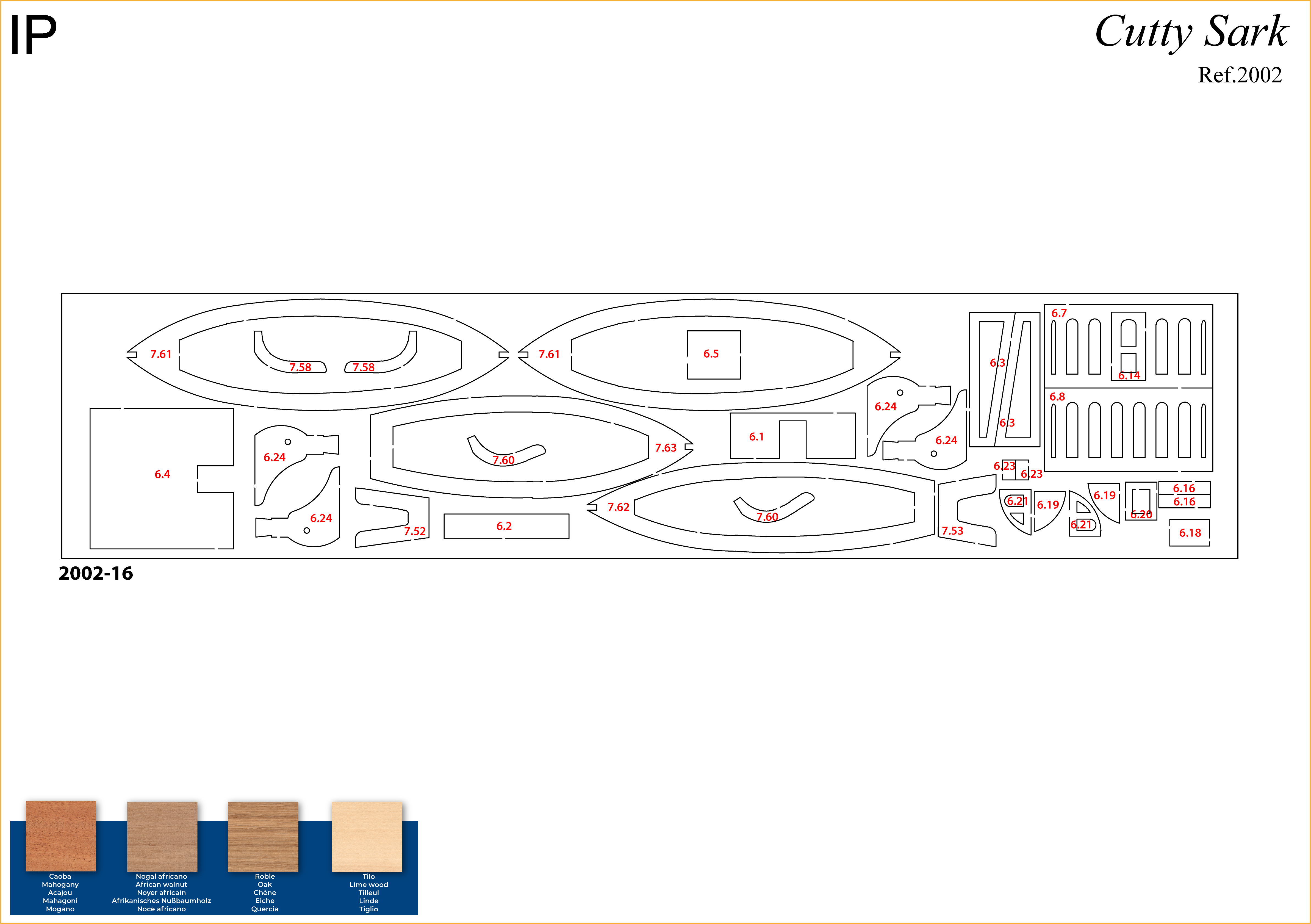
PARTS REFERENCE
PART NO. | IP-SHEET LOCATION | PART NO. | IP-SHEET LOCATION |
| 6.1 | 2002-16 | 6.16 | 2002-16 |
| 6.2 | 2002-16 | 6.18 | 2002-16 |
| 6.3 | 2002-16 | 6.19 | 2002-16 |
| 6.4 | 2002-16 | 6.20 | 2002-16 |
| 6.5 | 2002-16 | 6.21 | 2002-16 |
| 6.7 | 2002-16 | 6.23 | 2002-16 |
| 6.8 | 2002-16 | 6.24 | 2002-16 |
| 6.9 | 2002-23 (pack 5) | 6.44 | 2002-17 (pack 4) |
| 6.10 | 2002-21 (pack 5) | 6.45 | 2002-17 (pack 4) |
| 6.14 | 2002-16 / 2002-23 (pack 5) | 6.46 | 2002-17 (pack 4) |
| 6.15 | 2002-23 (pack 5) |
For extra support and guidance, John Builds Iconic Military Models demonstrates his build of the Cutty Sark on his YouTube channel, sharing 30+ years of wooden ship-building experience. Experts can be found on our Forum.
Step 1
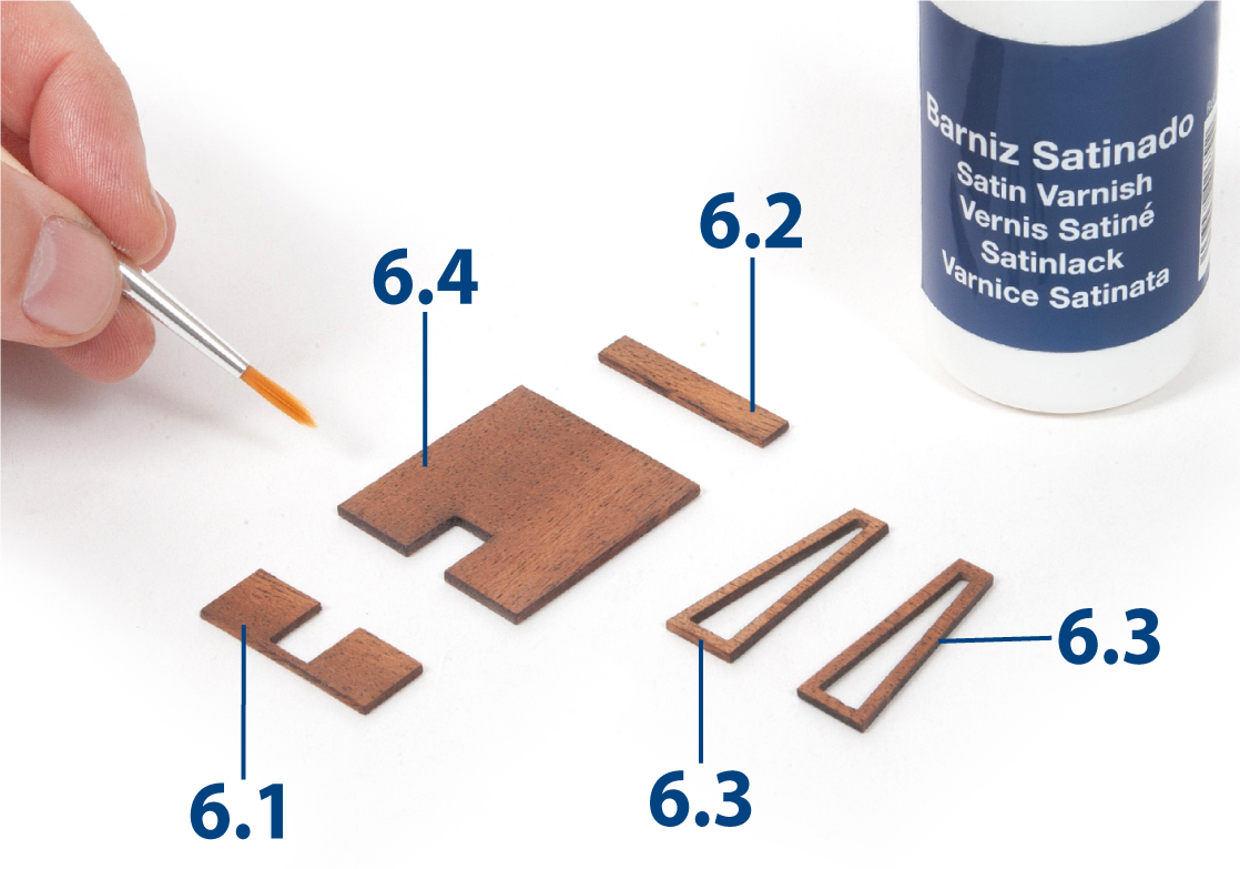
Sand parts 6.1 to 6.4, then varnish them.
Step 2
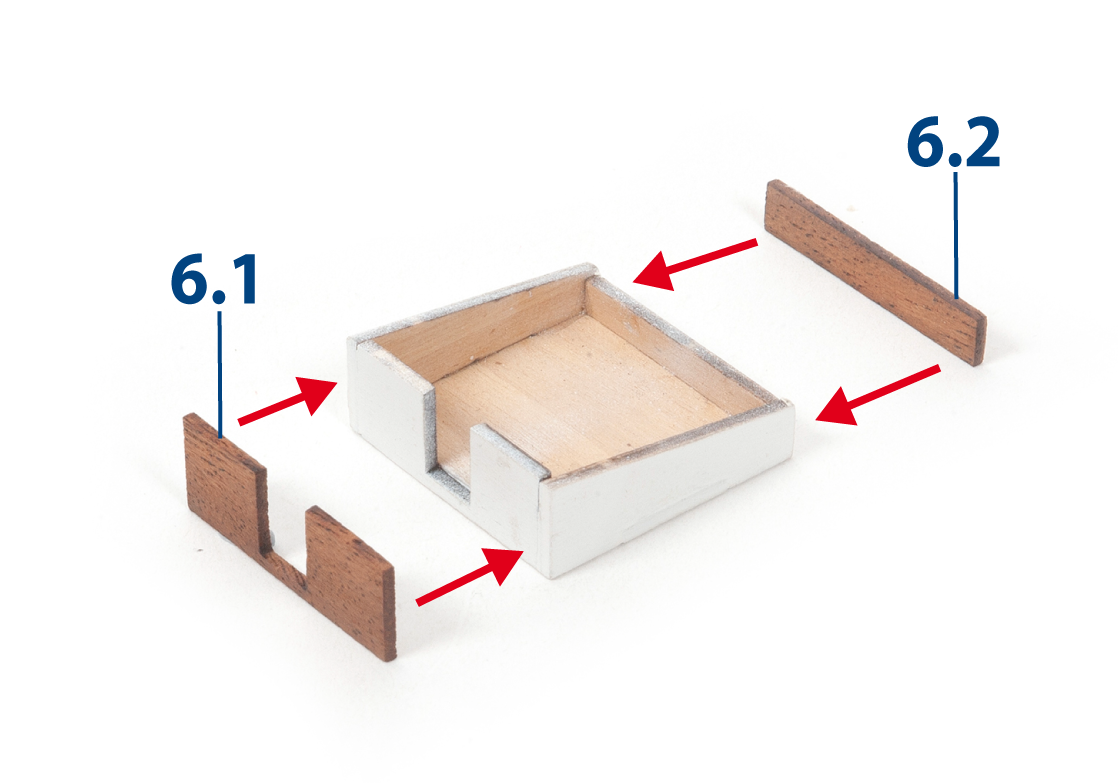
Glue parts 6.1 and 6.2 to the aft hatch, as shown.
Step 3
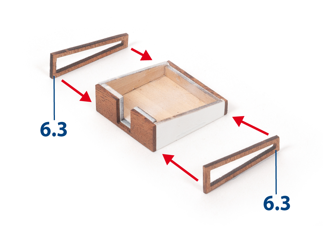
Glue parts 6.3 in place, as shown.
Step 4
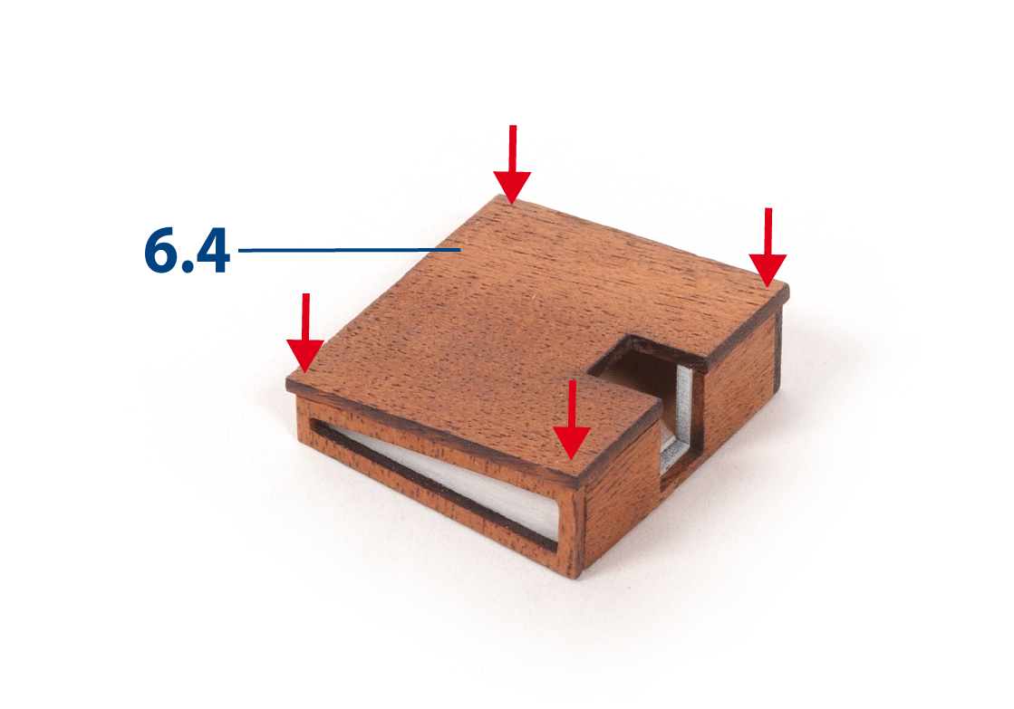
Glue part 6.4 on top, centred as shown.
Step 5
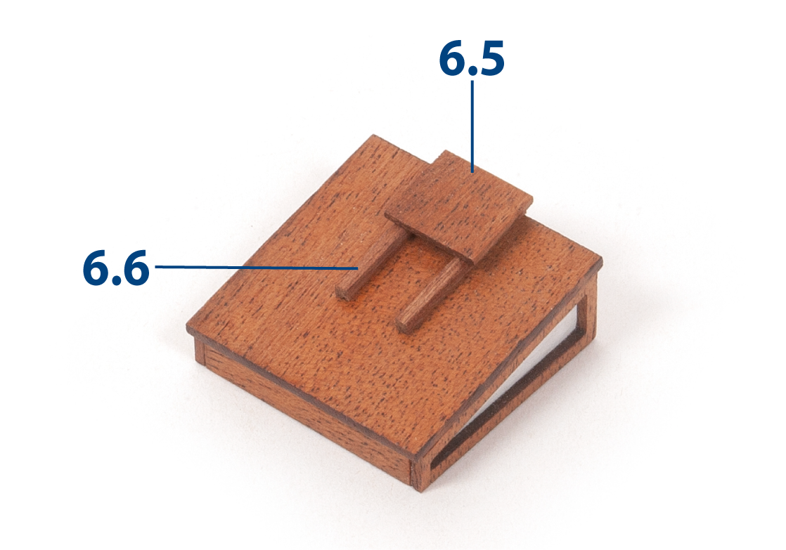
Cut parts 6.6 (2 x 2 x 23 mm mahogany) to length and glue them in place. Then glue part 6.5 on top, as shown.
Step 6
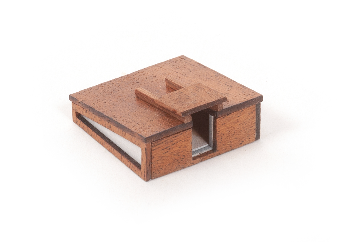
This picture shows the aft hatch from another angle.
Step 7
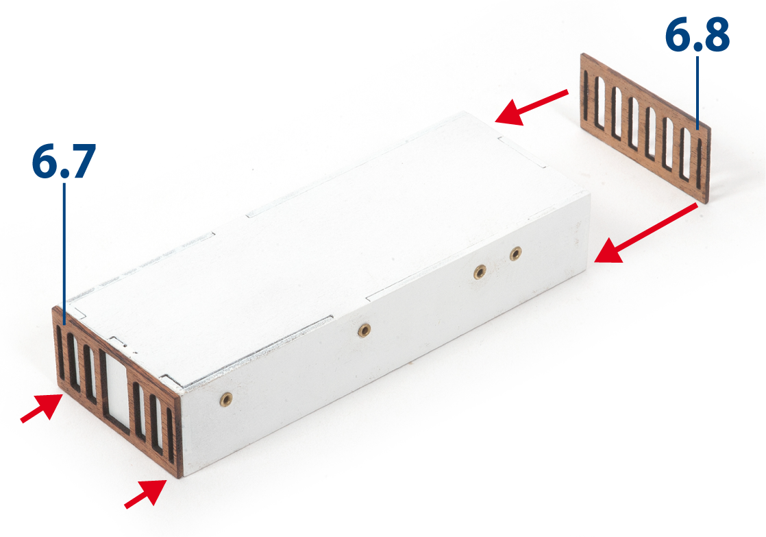
Glue parts 6.7 and 6.8 to the fore deckhouse. Test-fit the windows before gluing them in place.
Step 8
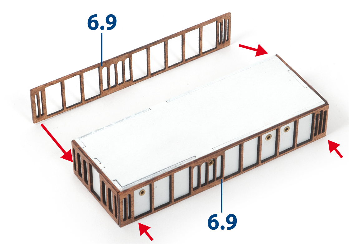
Glue parts 6.9 in place, as shown.
Step 9
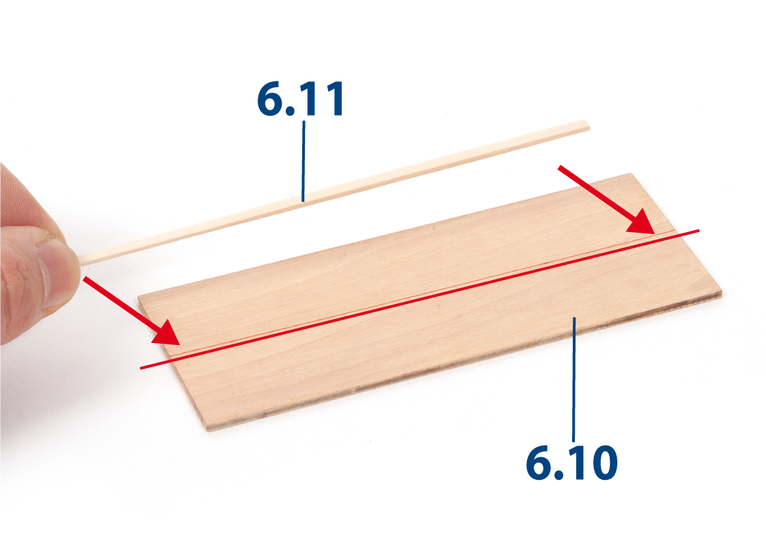
Cut parts 6.11 (1 x 3 x 120 mm lime wood) to length. Draw a line down the centre of part 6.10, then glue one part 6.11 along the line.
Step 10
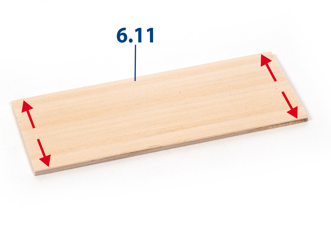
Glue additional parts 6.11 until the fore deckhouse roof is completely covered. Trim off the excess and sand the roof.
Step 11
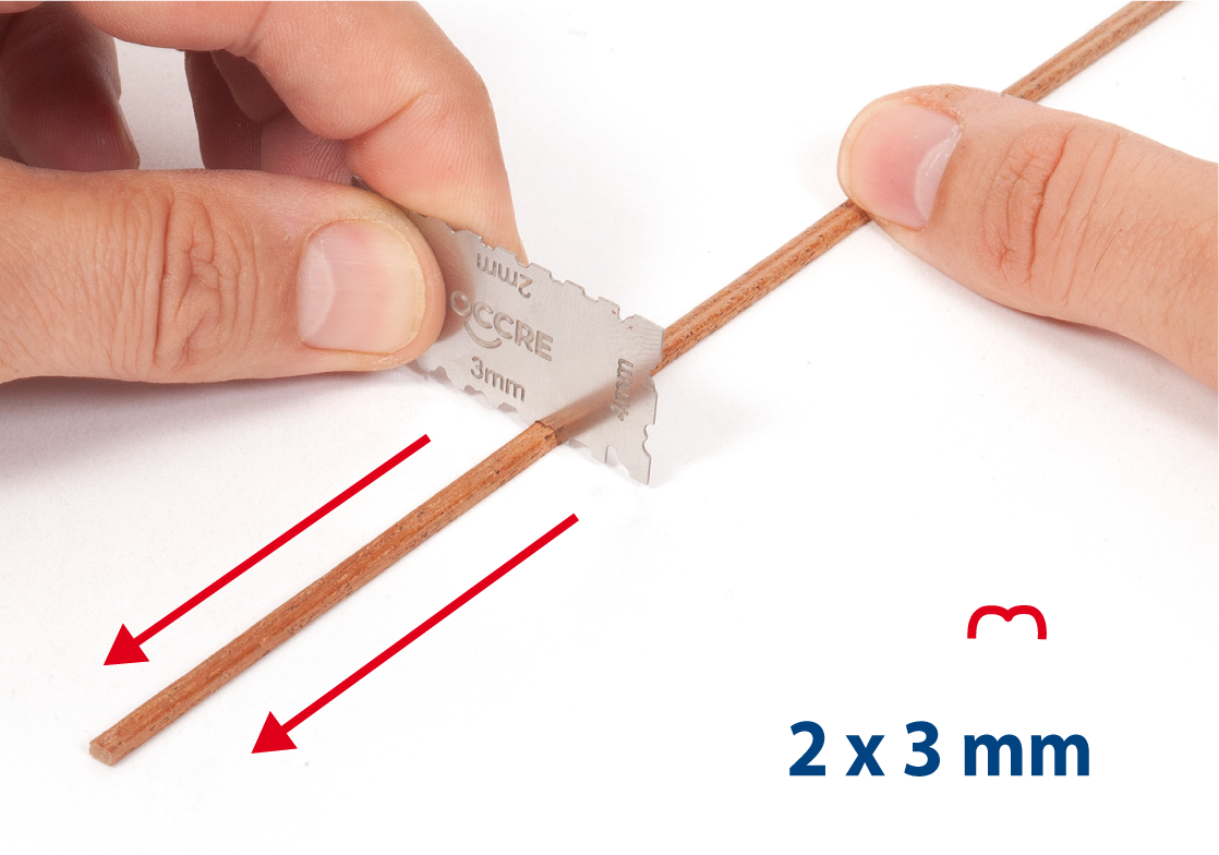
Use a grooving tool on a 2 x 3 mm mahogany strip, as shown.
Step 12
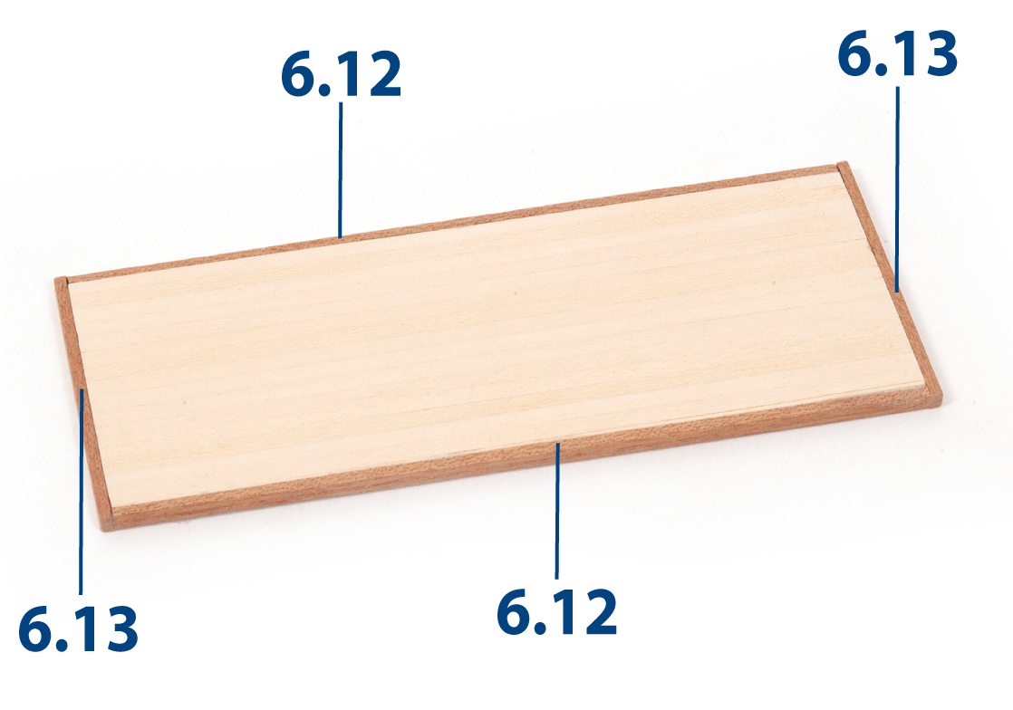
Cut the strip to length to create parts 6.12 ( 2 x 3 x 120 mm) and parts 6.13 (2 x 3 x 49 mm). Glue the parts to the roof, as shown.
Step 13
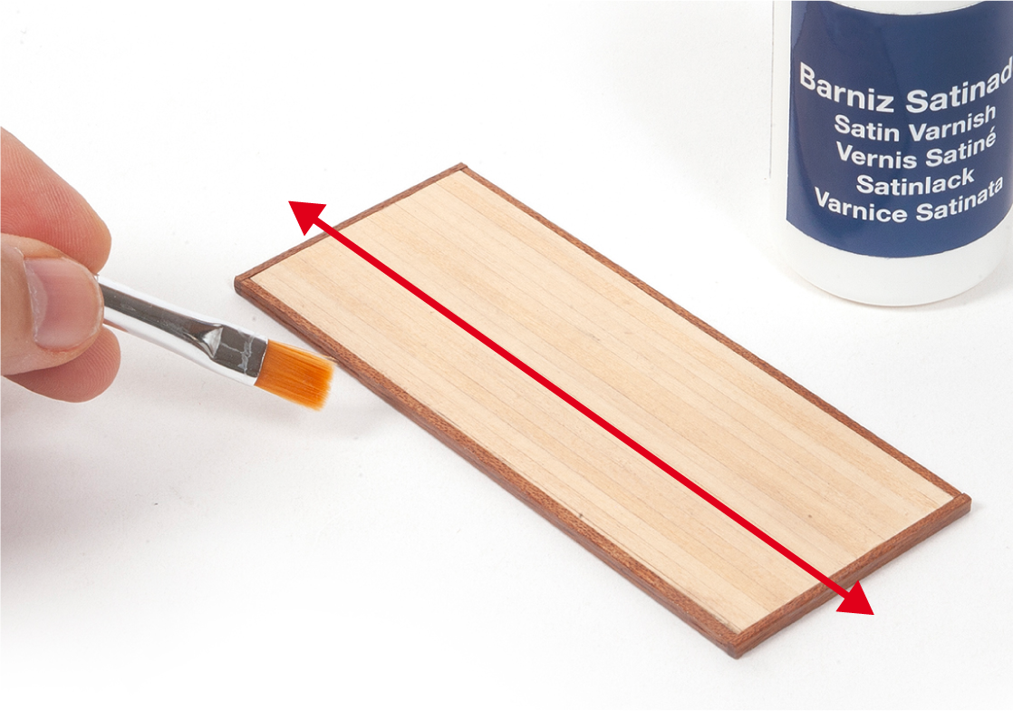
Varnish the roof.
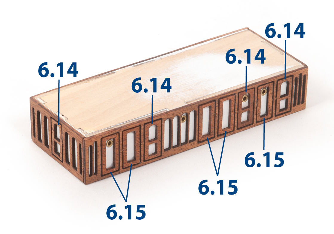
Step 14
Using tweezers, position parts 6.14 and 6.15 as shown, then glue them in place.
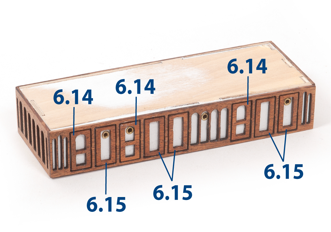
Step 15
Glue the remaining parts as shown.
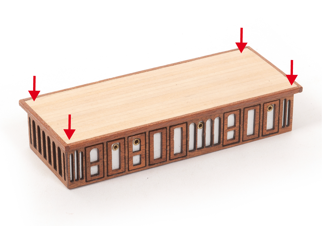
Step 16
Glue the roof to the fore deckhouse, centred as shown.
Step 1
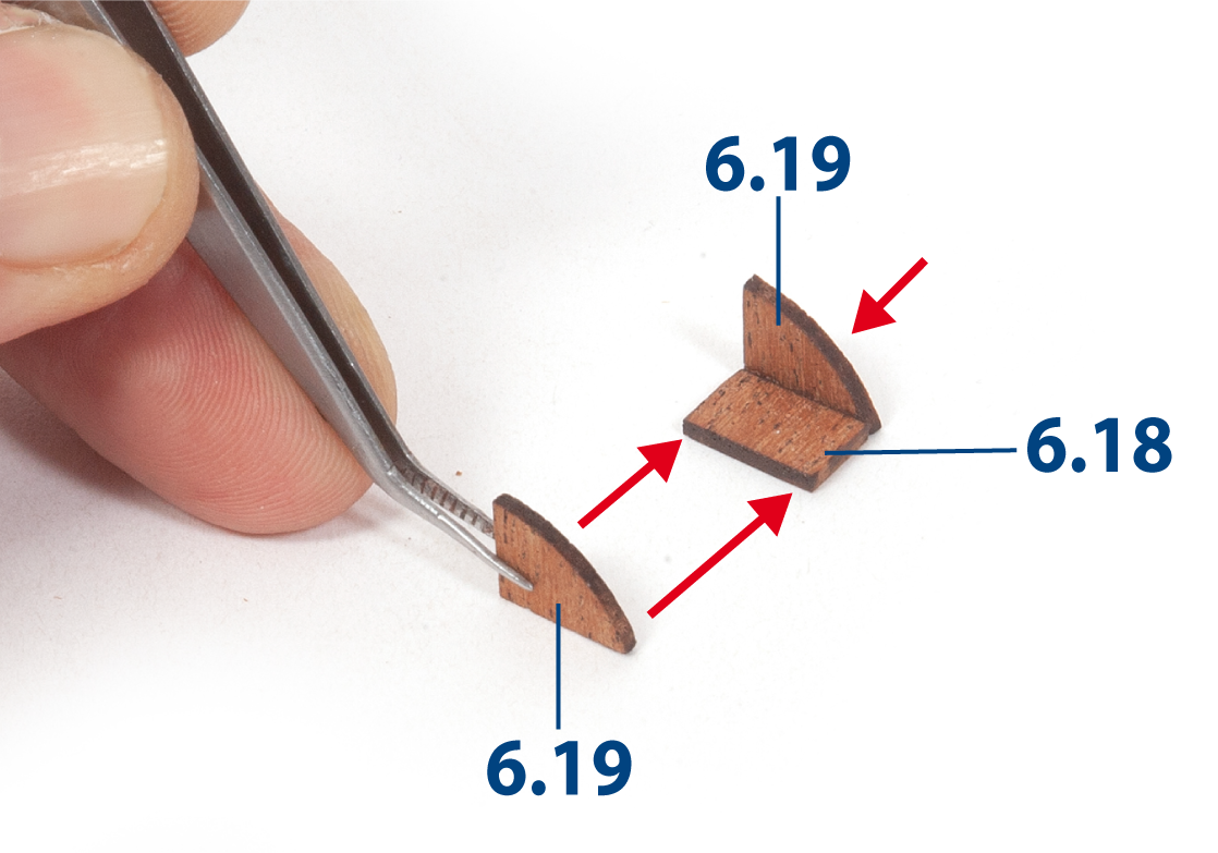
Glue parts 6.18 and 6.19 together.
Step 2
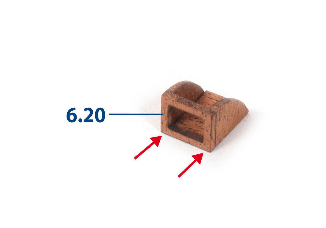
Glue part 6.20 to the front of the assembly.
Step 3
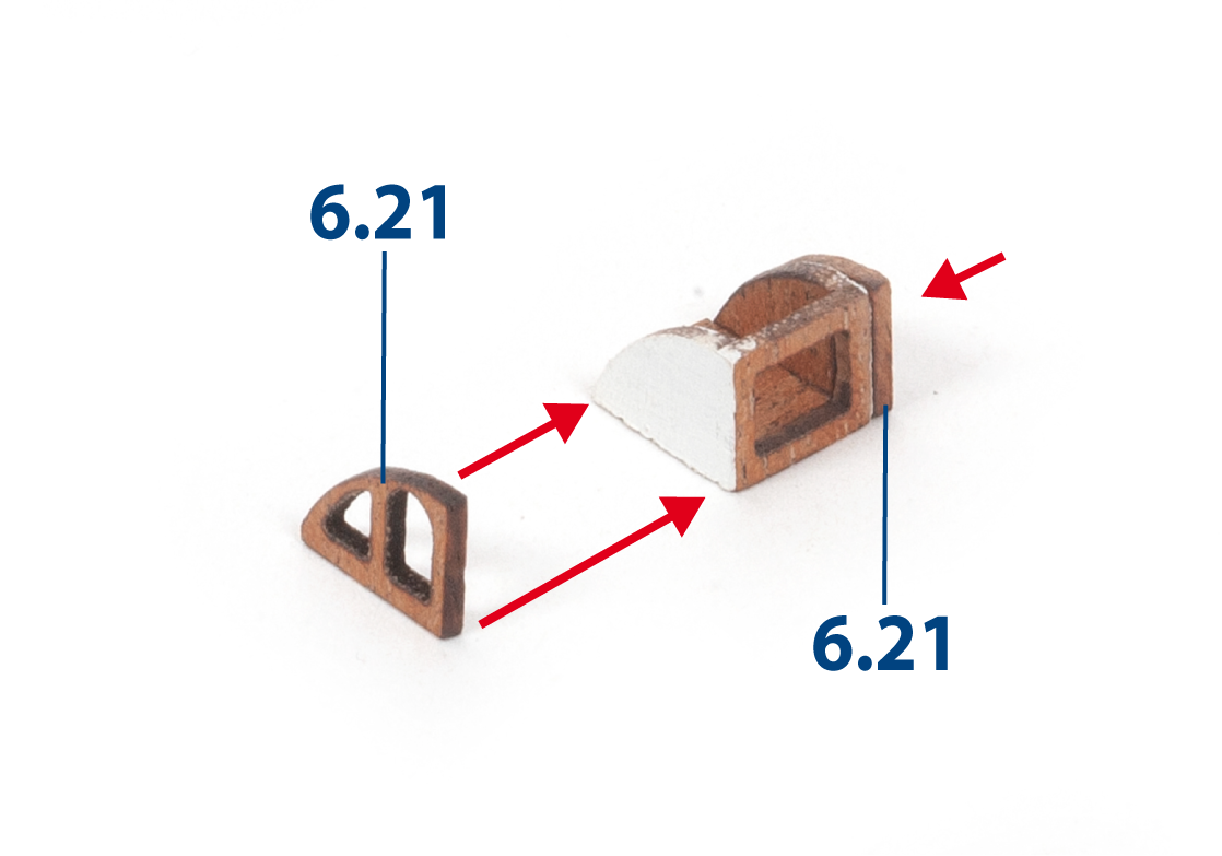
Paint the sides of the assembly white, then glue parts 6.21 in place.
Step 4
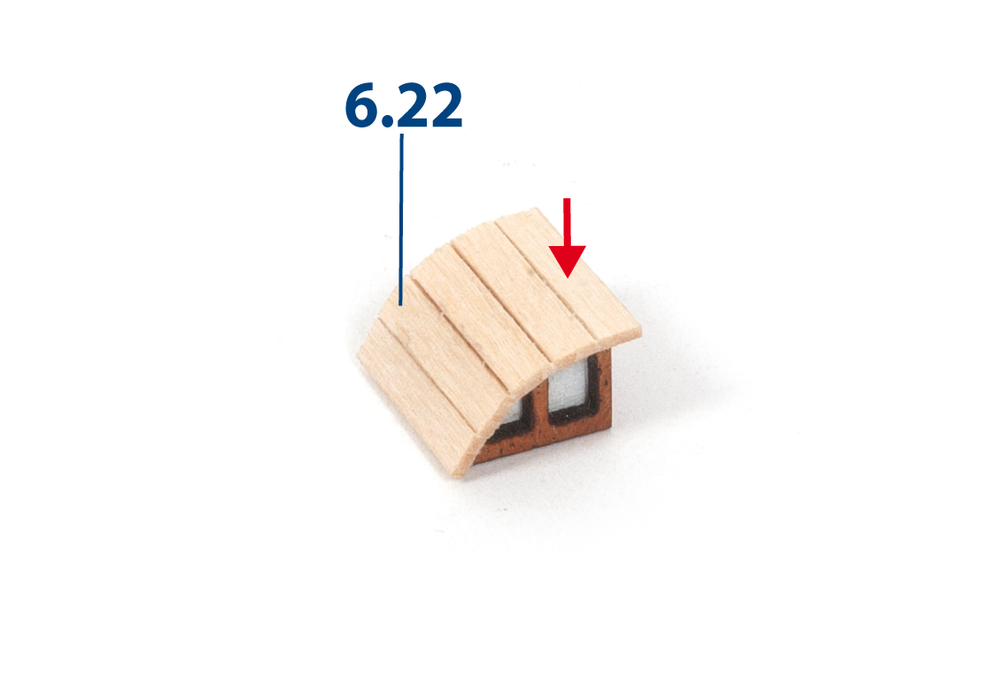
Cut parts 6.22 to length (1 x 3 x 15 mm lime wood) and glue them in place, as shown.
Step 5
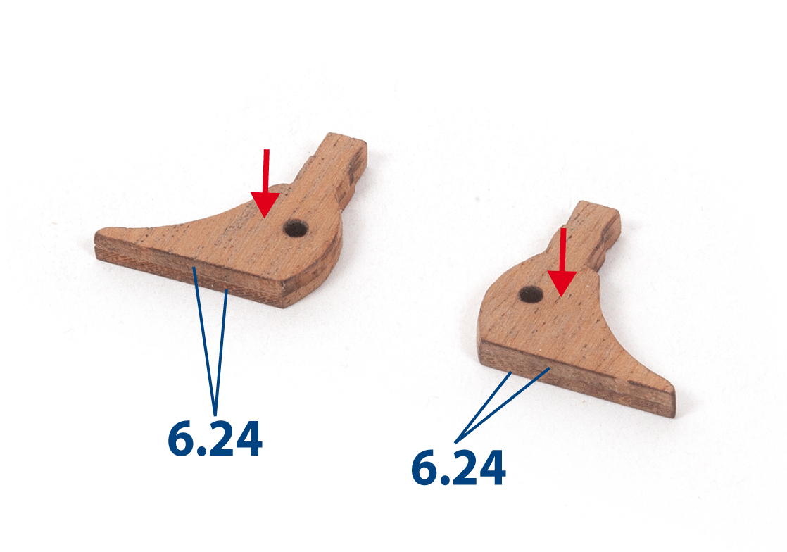
Glue parts 6.24 together in pairs. Sand and varnish the two completed assemblies.
Step 6
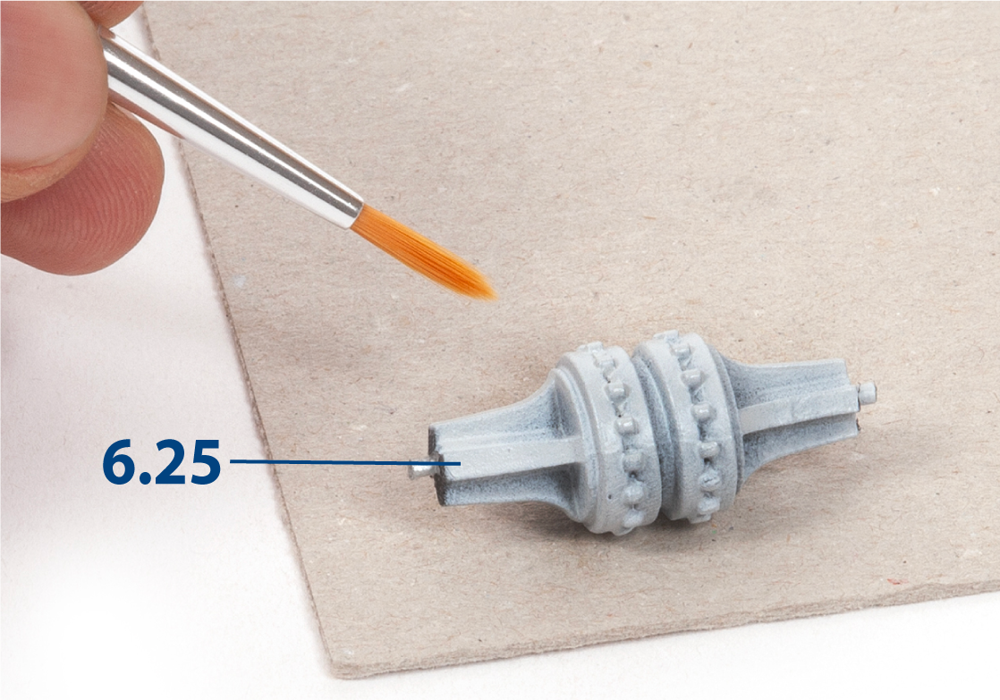
If you wish to repaint part 6.25, first clean it with soap and water or alcohol. Apply primer and allow it to dry before painting.
Step 7
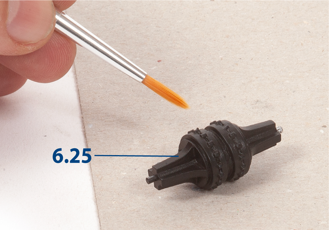
Paint part 6.25 black.
Step 8
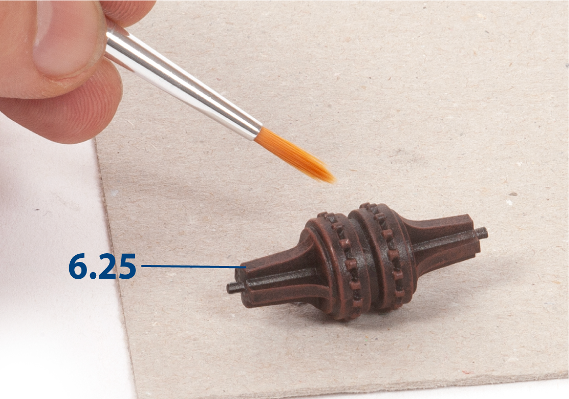
After the black paint has dried, apply dark red paint using the dry-brush technique so that only the raised details are highlighted.
Step 9
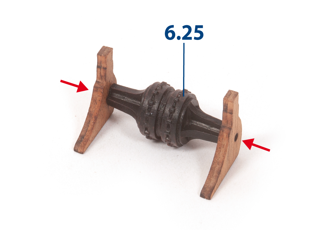
Glue the parts together as shown.
Step 1
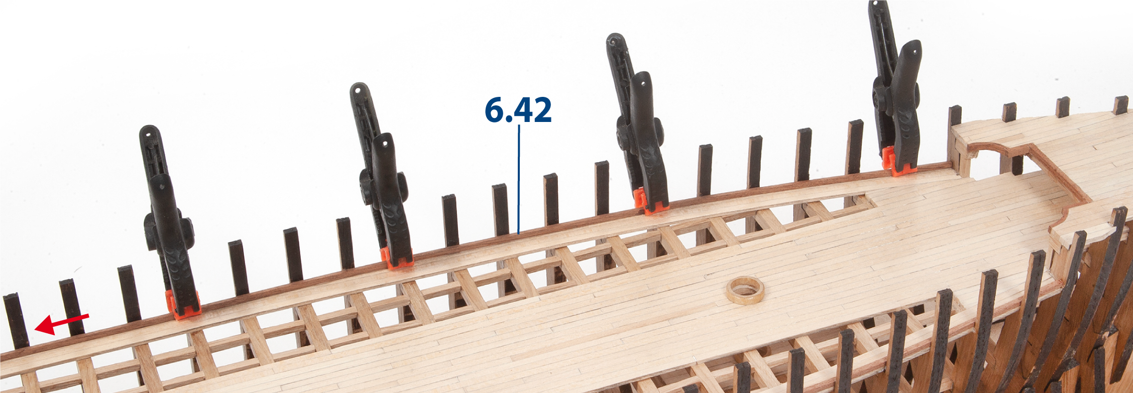
Test-fit and glue one strip 6.42 (2 x 2 x 575 mm mahogany) to each side of the deck.

Step 3
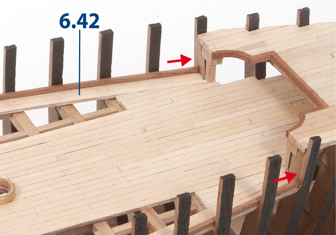
This image shows the strips at the stern.
Step 4
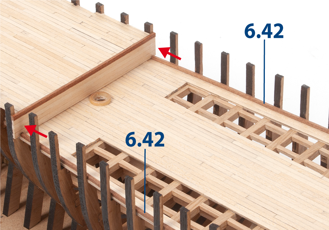
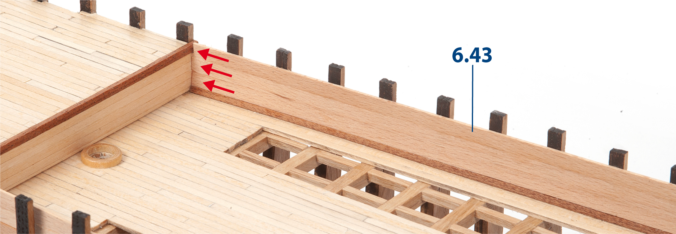
Glue parts 6.43 (1 x 5 x 575 mm lime wood) on top of the previous strips, running from bow to stern.
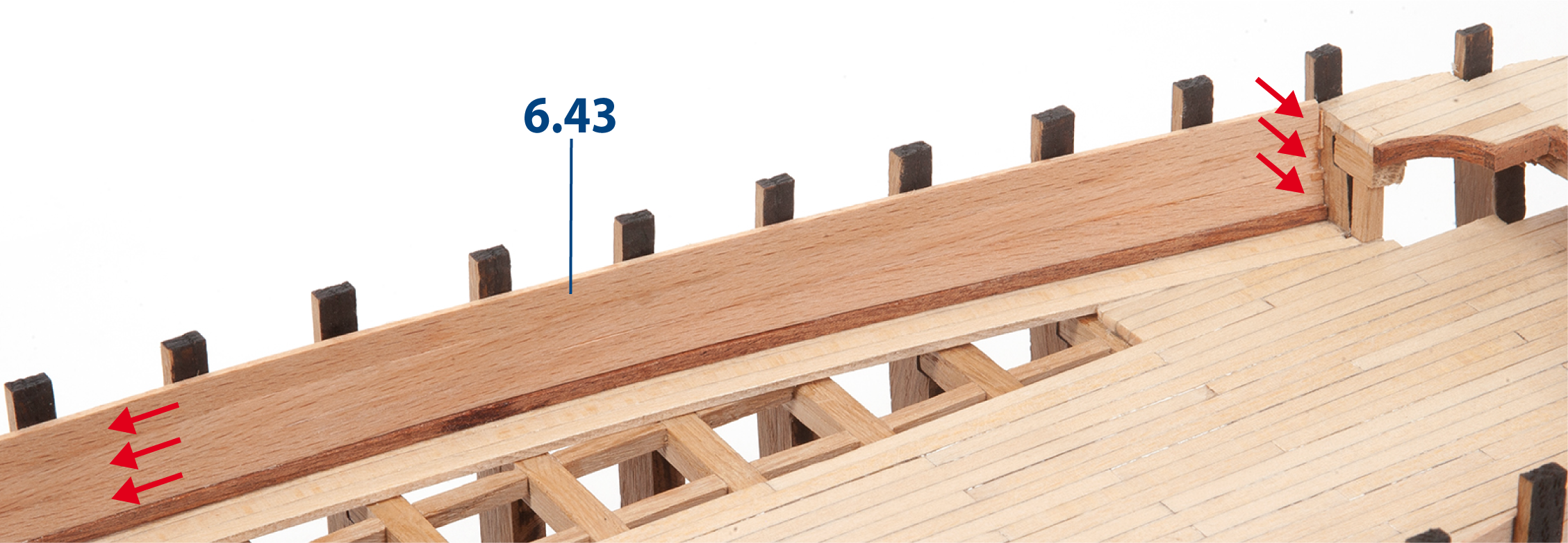
Step 5
This image shows the strips in place at the stern. Repeat this procedure on the opposite side of the ship.
Step 6
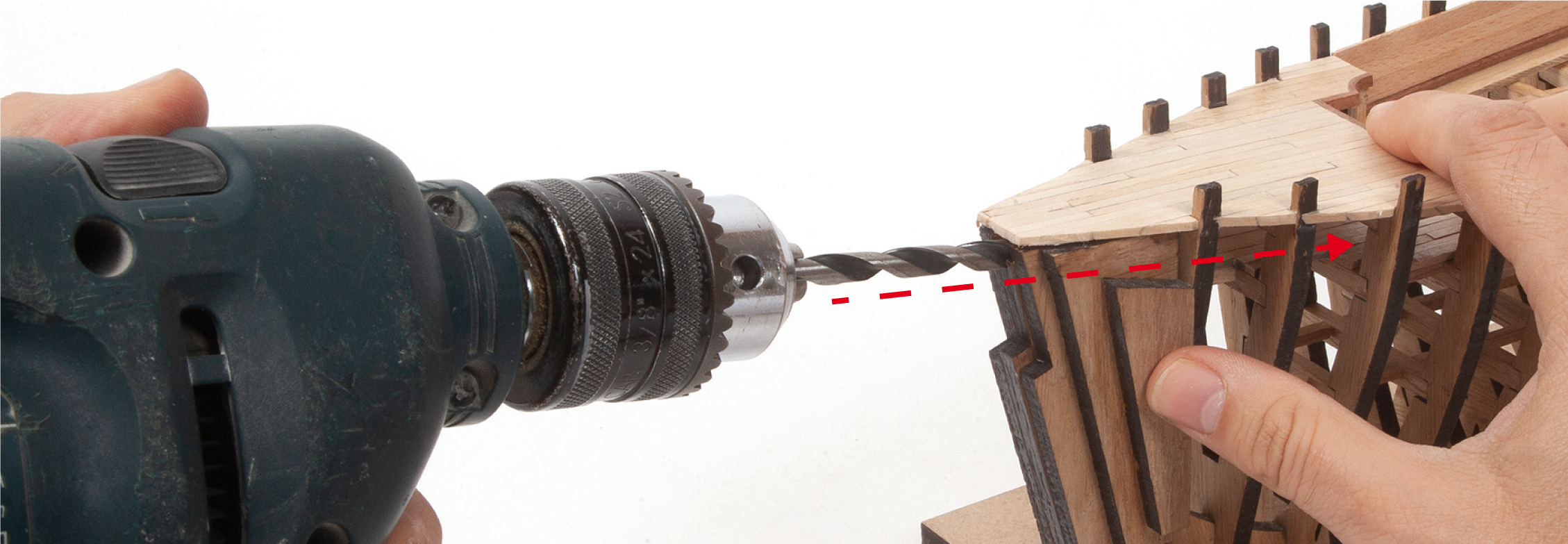
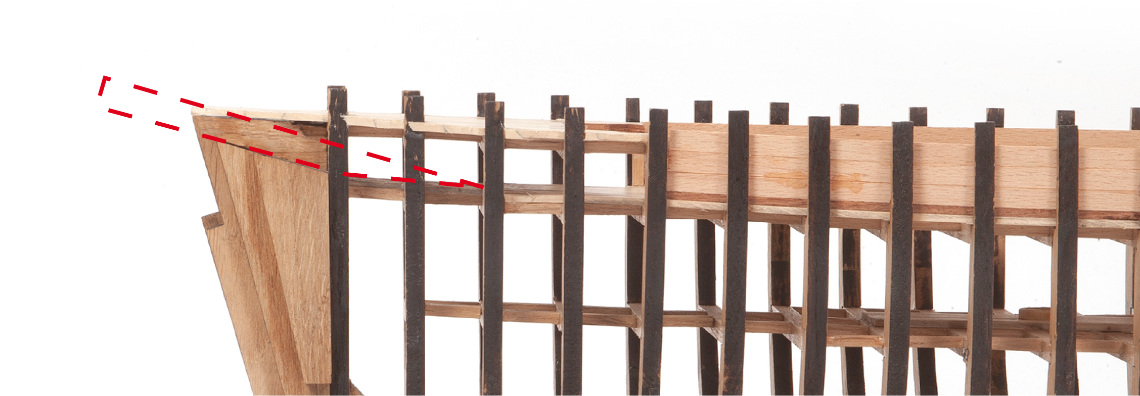
Drill an ø8 mm hole for the bowsprit in the bow of the hull.
Refer to image b for the correct drilling angle for the bowsprit. You can complete this step later if you prefer.
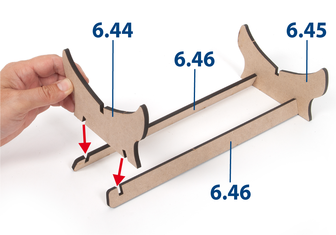
Step 1
Insert and glue parts 6.44 and 6.45 to parts 6.46 to assemble the work stand.
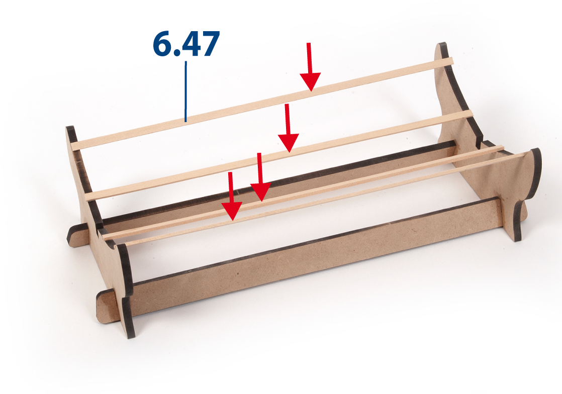
Step 2
Cut parts 6.47 (2 x 5 x 265 mm lime wood) and glue them in place as shown.
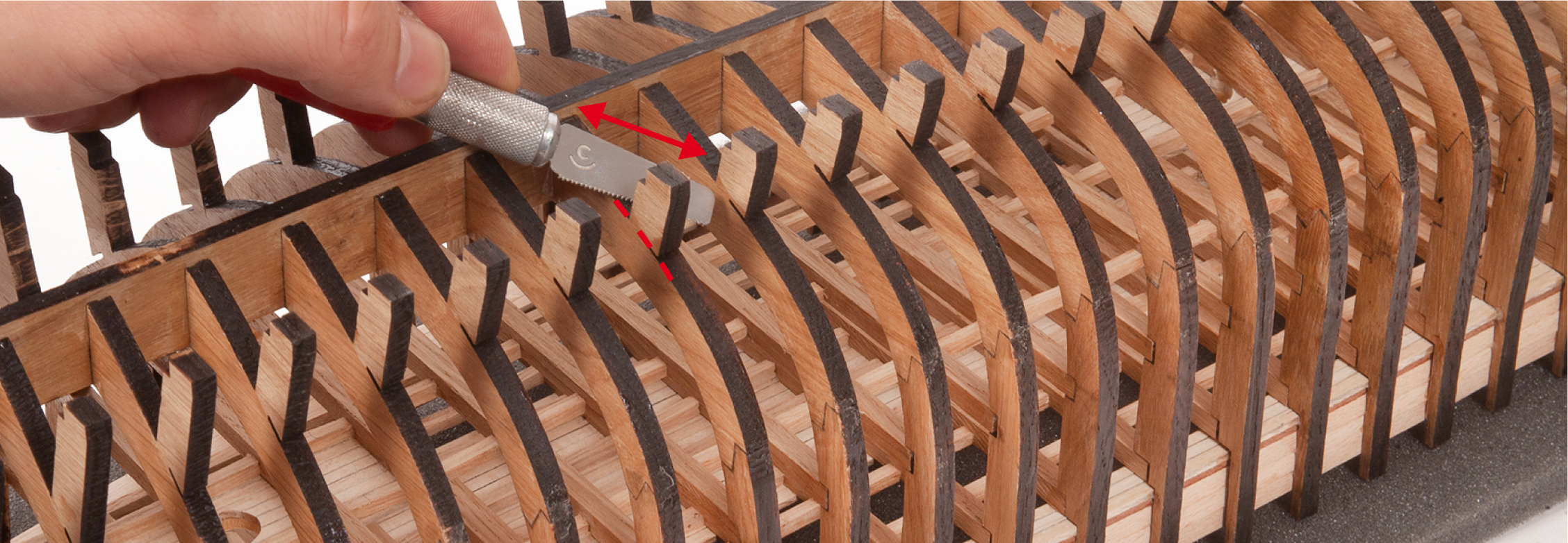
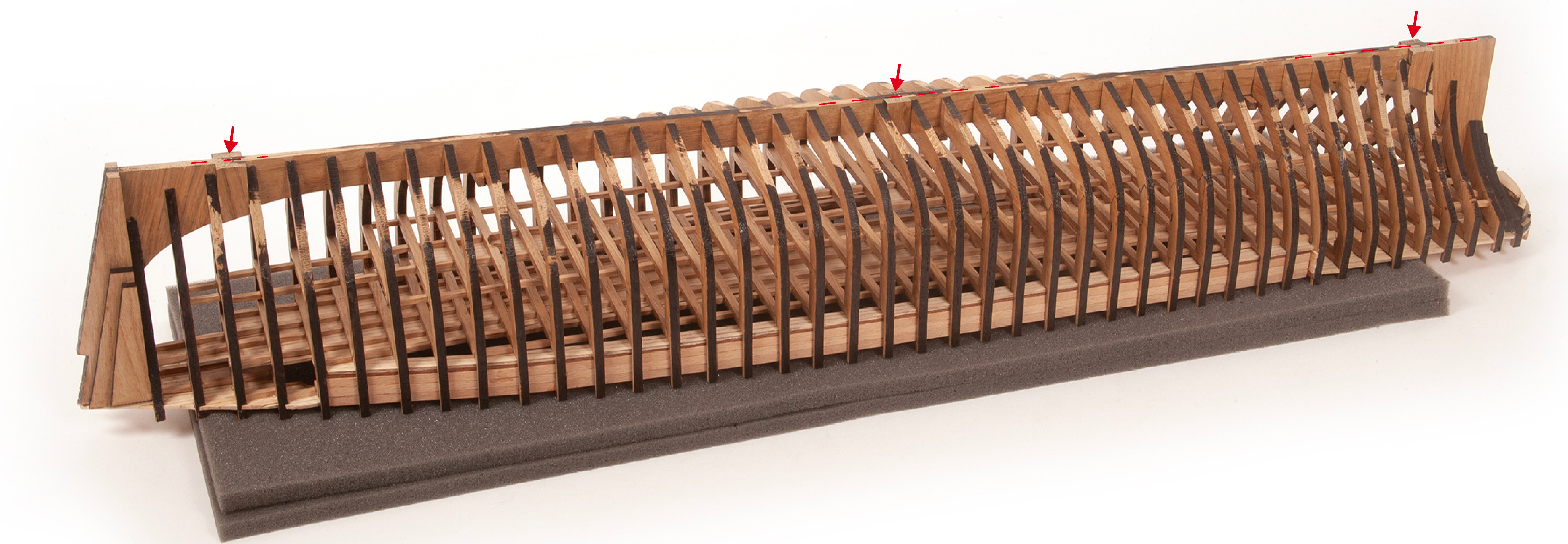
Step 4
Cut off the false keel extensions. Sand the areas smooth.
Step 5
Place the hull on the work stand and check that the hull sits correctly.