Pack 07
BUILD INSTRUCTIONS
Advice from the experts
Spare screws are included with each part. Occasionally, you may be instructed to keep spare or unused screws for a later stage. Keep these spares in a safe place and label them correctly.
Please make sure you don’t mix up the screws. They look quite similar, but the threads do vary slightly. Using the wrong screws may damage the parts. Only use the correct size screwdriver that fits the screw head firmly.
When securing parts together using multiple screws, fit each screw loosely to ensure all the parts are correctly aligned before gently tightening them firmly, but not overtight, in the order in which you placed them.
The screwdriver can be magnetized by stroking it with a magnet (fridge magnet, etc.) enabling it to hold the screws and make assembly easier.
If a screw is tight going into a metal part, do not force it as you may shear the head off. Remove it and put a tiny smear of Vaseline, soap or light oil on the thread. That will lubricate it and make it easier to tighten.
Some parts will require a little glue for assembly. Please apply glue sparingly and use a cocktail stick so that you don’t use too much nor apply the glue too heavily. We recommend superglue gel or Extra Thin Liquid modeling glue. Where possible, parts should be test-fitted in place before gluing.
Make sure you have good ventilation when using adhesives and to replace caps firmly.
Use a magnet to help find screws that have fallen on the floor.
Use masking tape to hold parts temporarily in place.
Cut parts from a sprue (framework) with side cutters or a craft knife. Side cutters tend to be easiest.
During the course of this build, you will receive many pieces that you will assemble immediately – following the instructions in the corresponding stage – and other pieces that you should store safely to one side, for use in future assembly stages.
Always protect the paint finish on components by placing a cutting mat, sheet of white paper or soft cloth on your work surface.
When plugging in wires, ensure the power is switched off. Tweezers can be used to fit the PVC wires by gripping carefully around 5mm from the end of the wire. If a wire needs to be removed from a socket, do not pull on the wire as this could damage the connection. Grip the plug with tweezers to remove it.
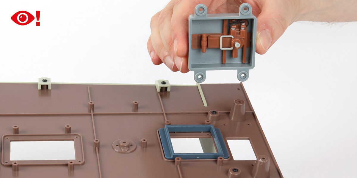
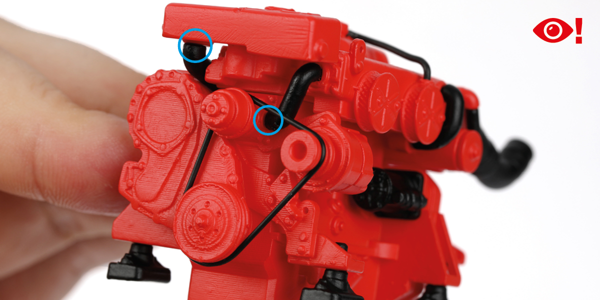
 When you see this symbol, pay attention to the instruction text in bold and check the orientation of the parts in the image as this will be particularly important for assembly in later stages.
WARNING: Some parts are assembled using magnets. These magnets can cause serious injury if they are swallowed. Keep away from children. If you suspect a magnet has been swallowed, seek medical help straight away.
This is not a toy. Not suitable for children under 14 years old due to small parts. Adult supervision required.
PACK 07 PARTS
Step 1
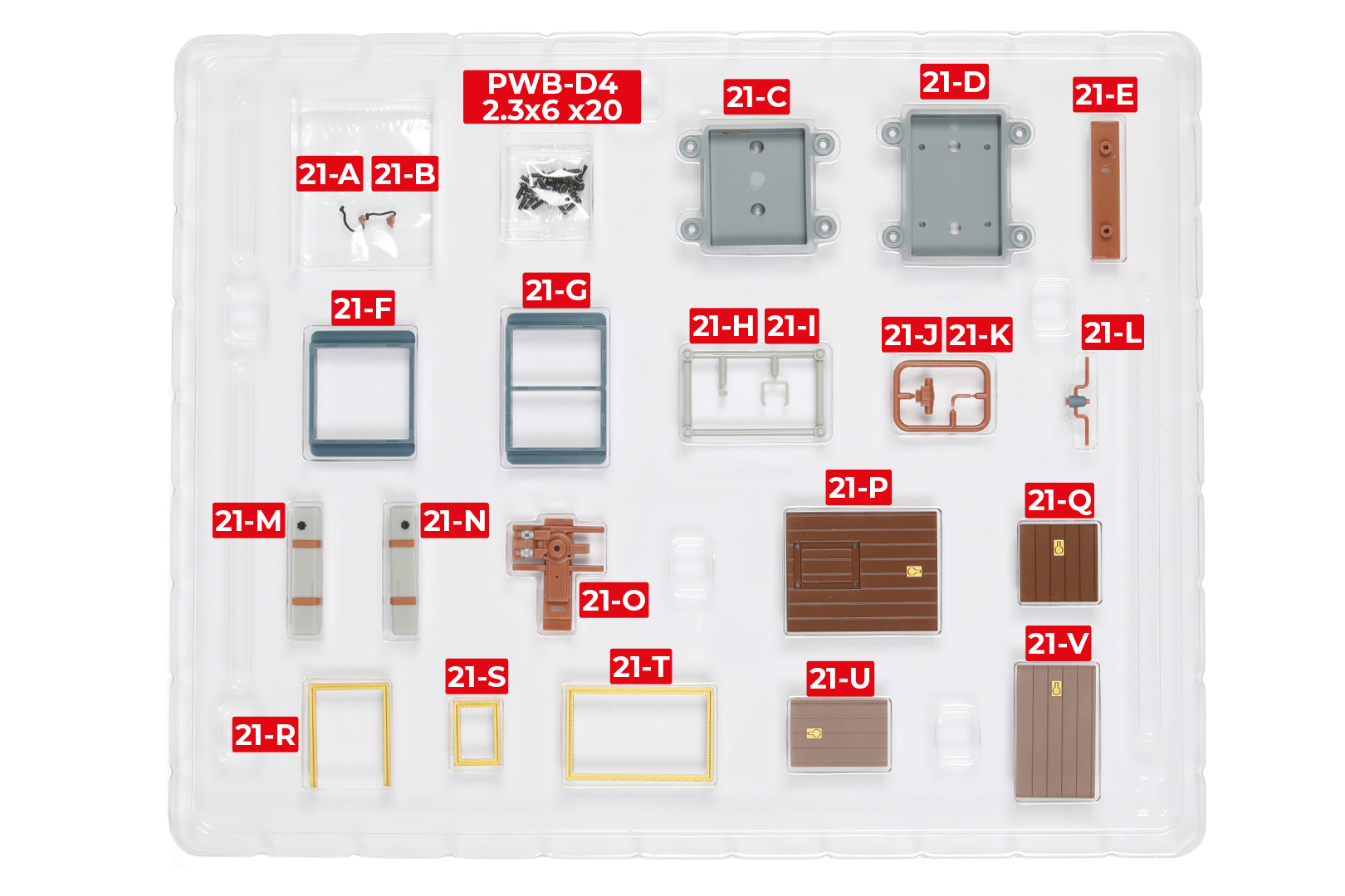
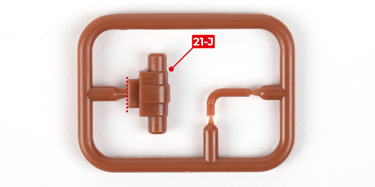
Cut part 21-J from the sprue.
Step 2
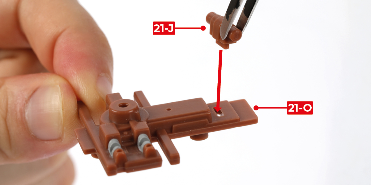
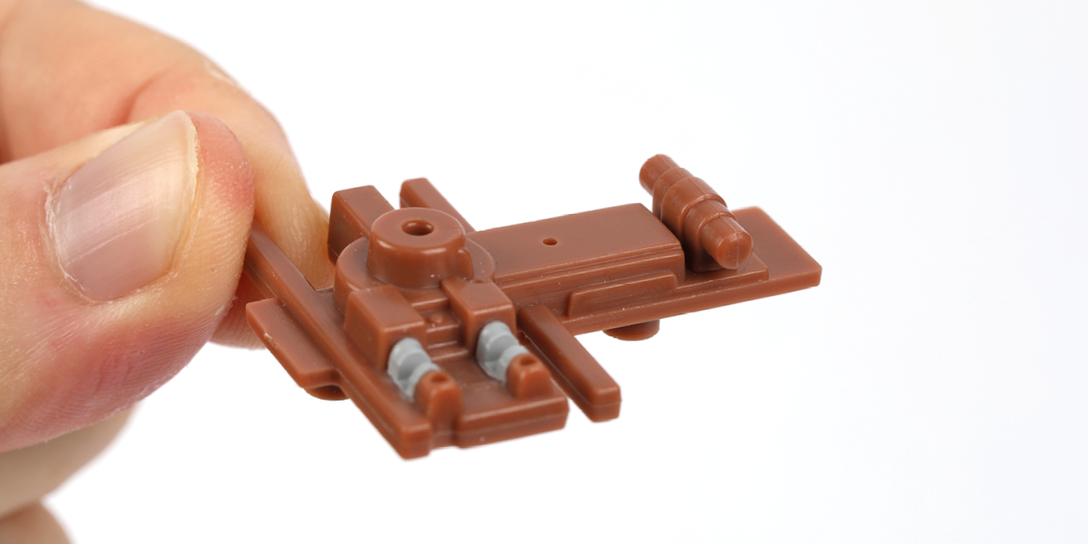
Glue part 21-J to part 21-O.
Step 3
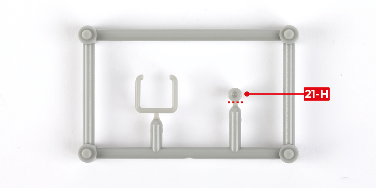
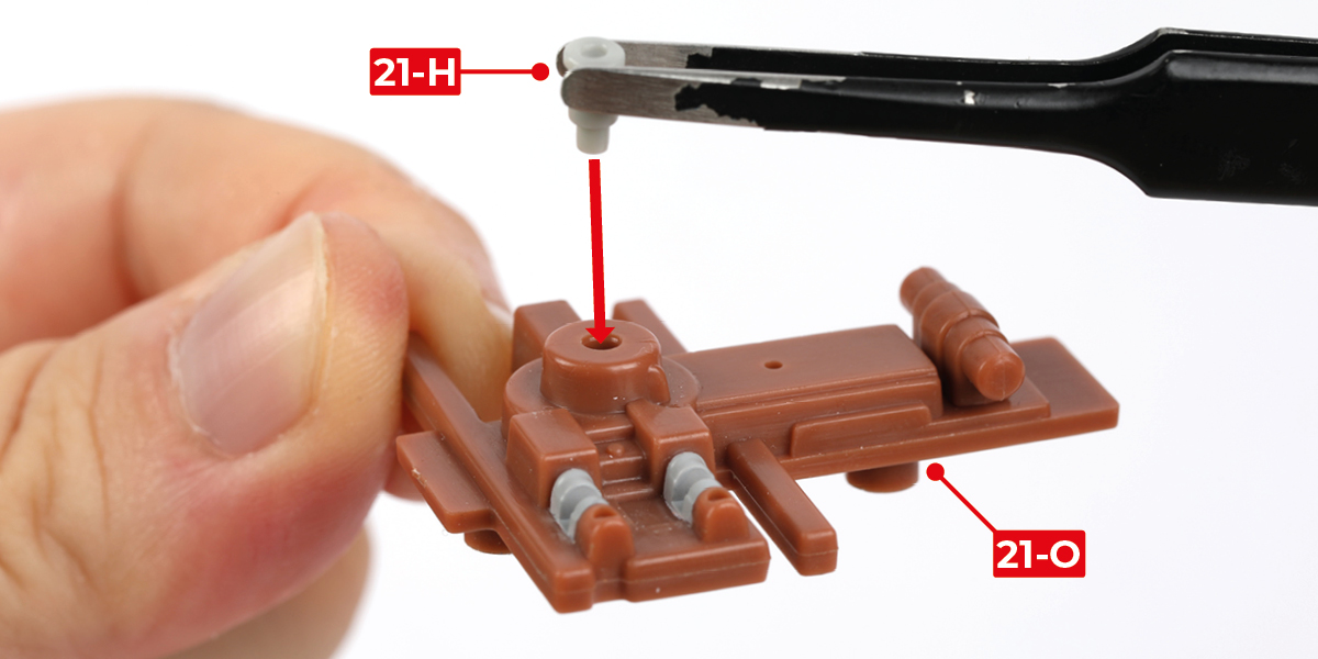
Cut part 21-H from the sprue.
Step 4
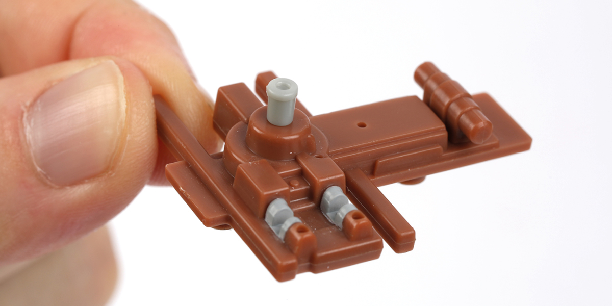
Glue part 21-H to part 21-O.
Step 5
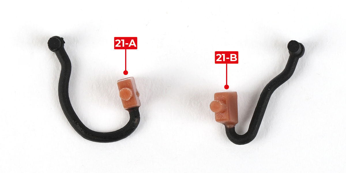
Identify parts 21-A and 21-B.
Step 6
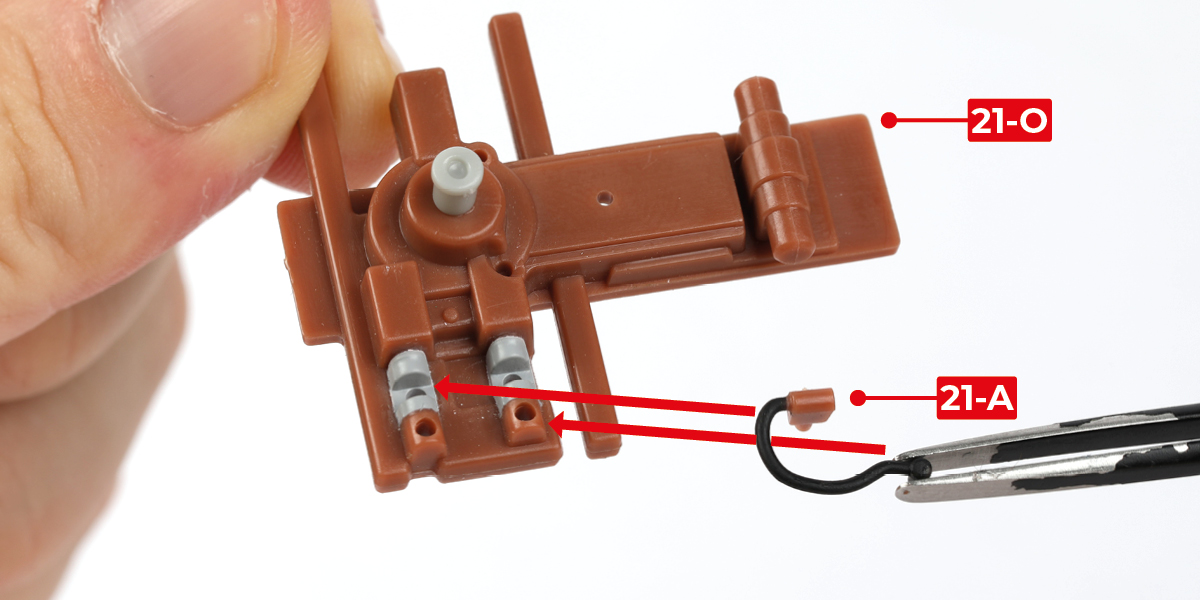
Glue parts 21-A and 21-B to part 21-O, as shown.
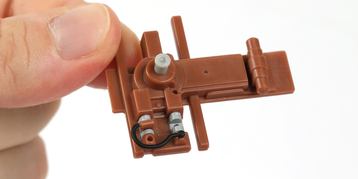
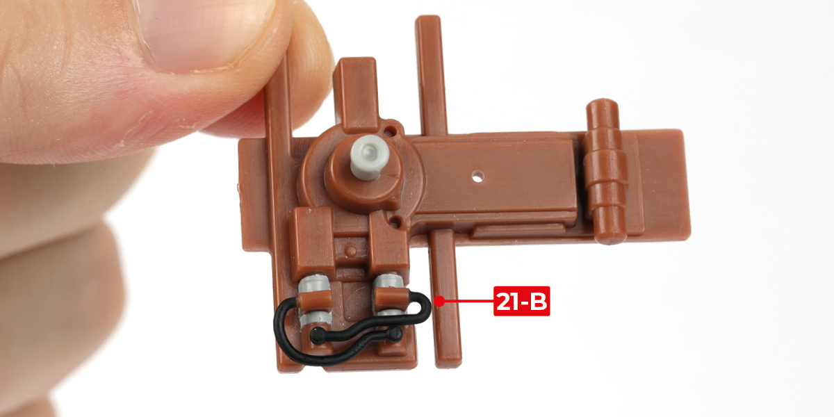
Step 7
Cut part 21-I from the sprue.
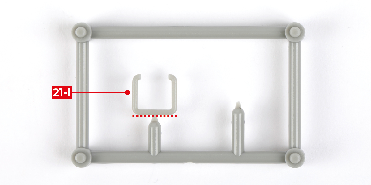
Step 8
Glue part 21-I to part 21-O.
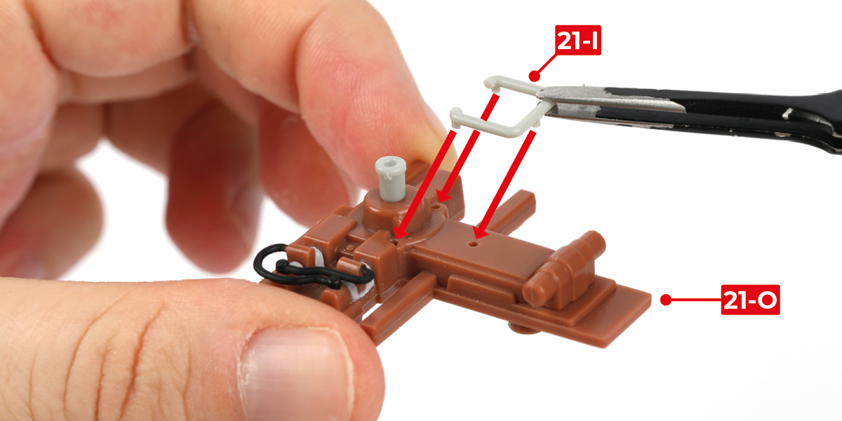
Step 9
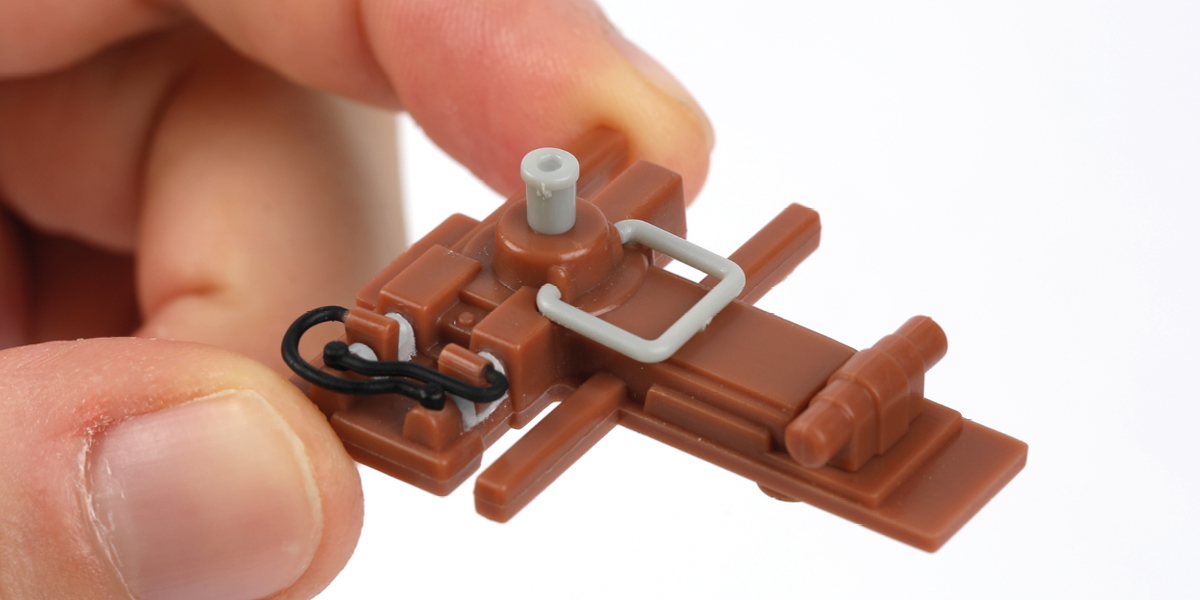
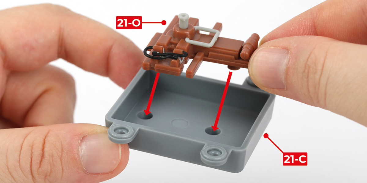
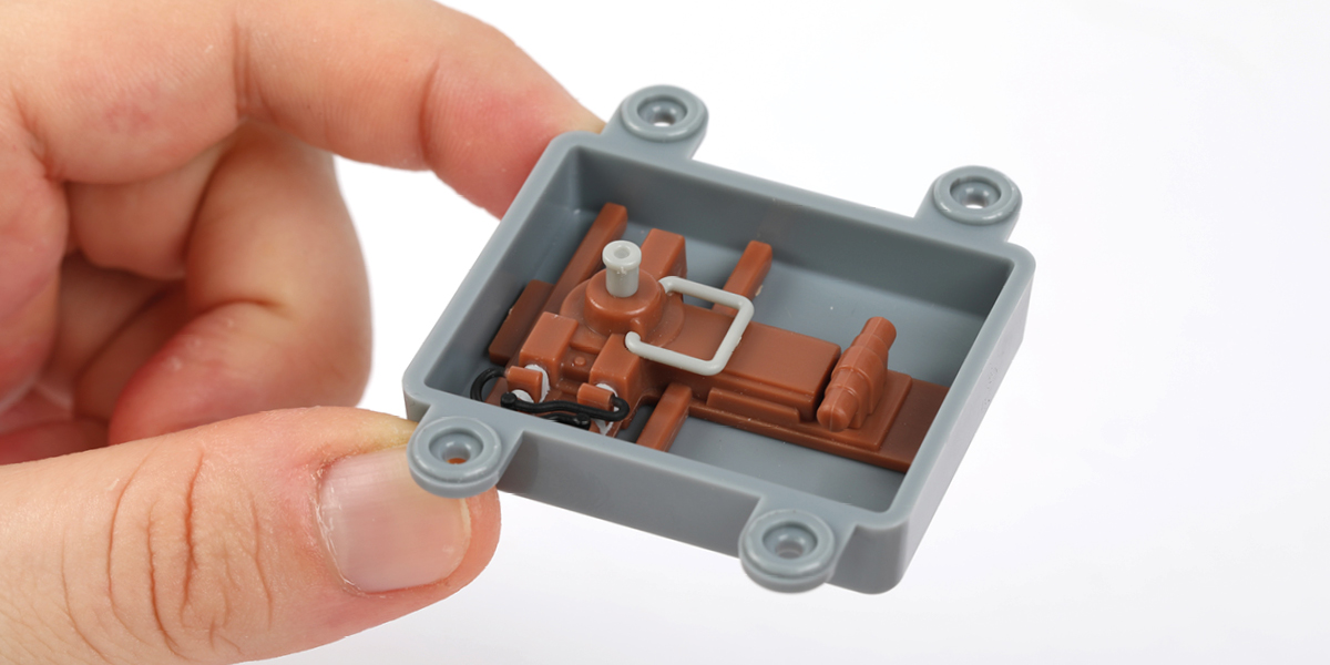
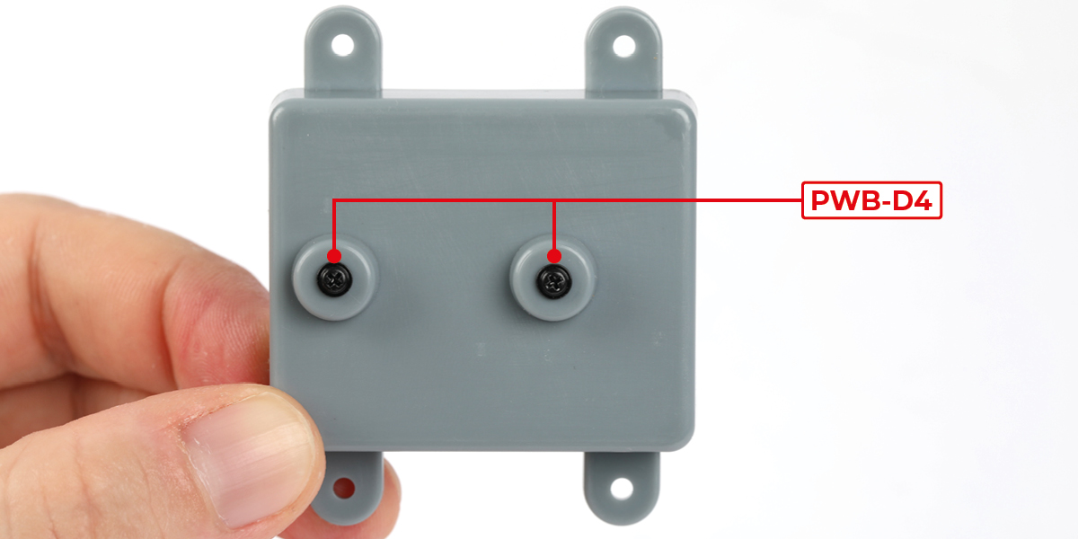
Place the steering assembly into part 21-C, then secure the parts together using two PWB-D4 screws.
Step 10
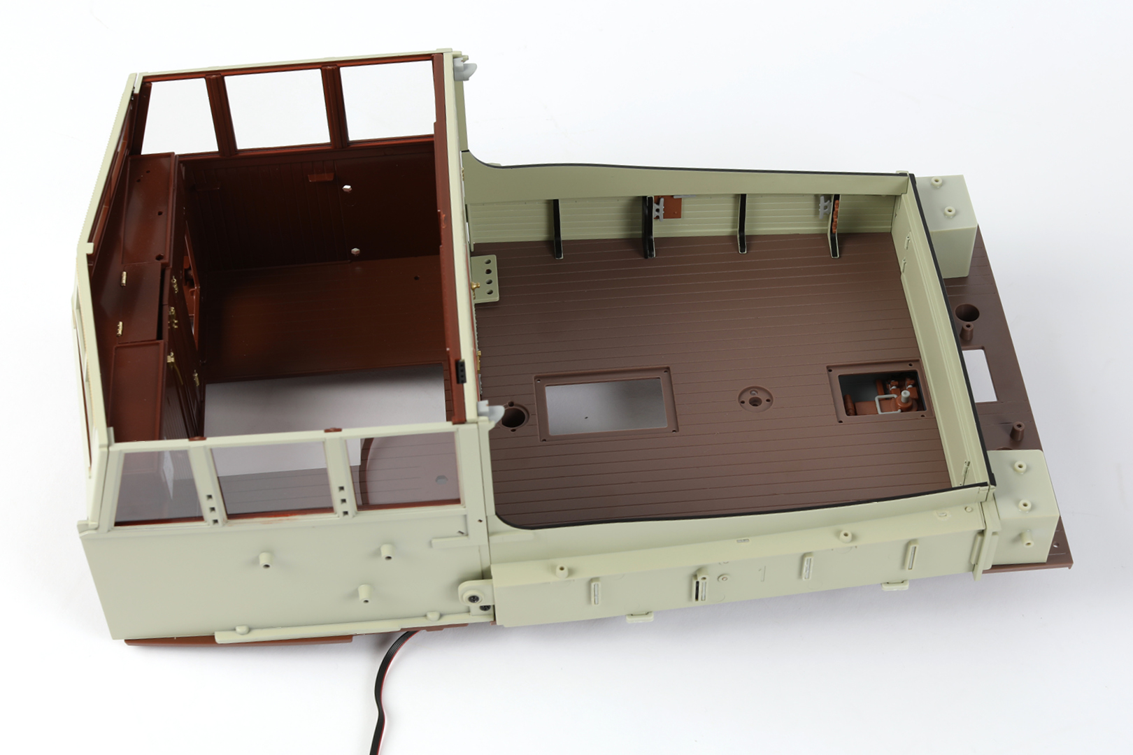
Take the aft deck/galley assembly completed in stage 29, turn it upside down, and position part 21-F as shown.
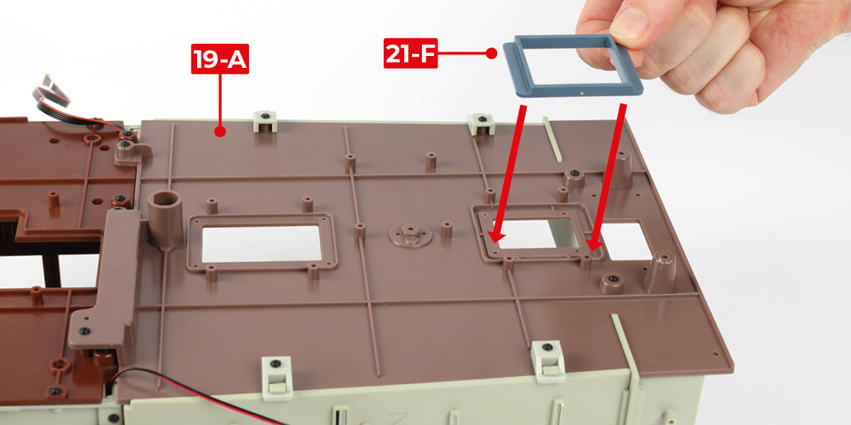
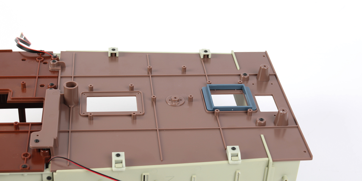
Step 11
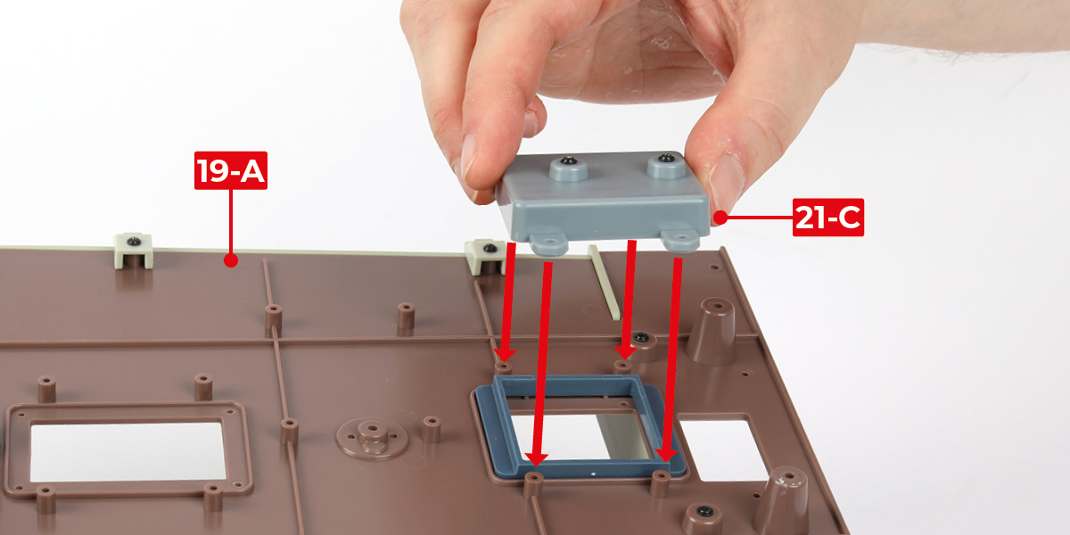
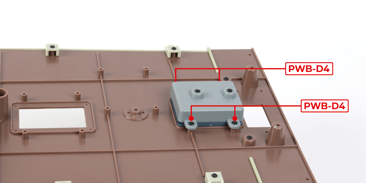
Ensure the steering assembly is in the orientation shown in image a. Secure the steering assembly to part 19-A using four PWB-D4 screws.
STAGE COMPLETE
Step 1
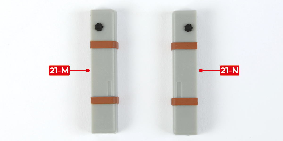
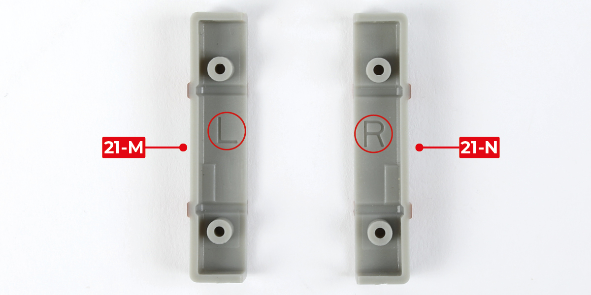
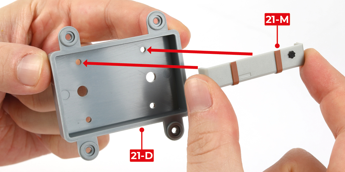
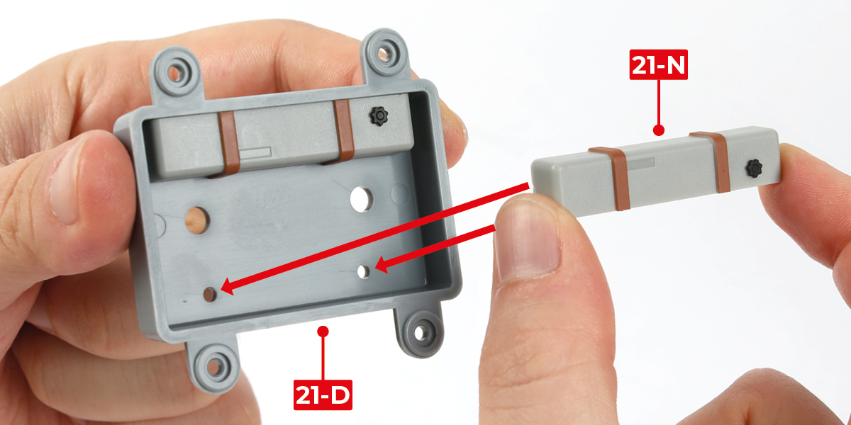
Identify parts 21-M (letter L) and 21-N (letter R).
Step 2
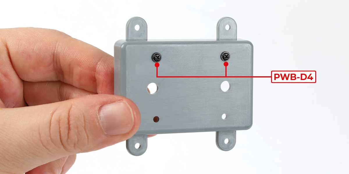
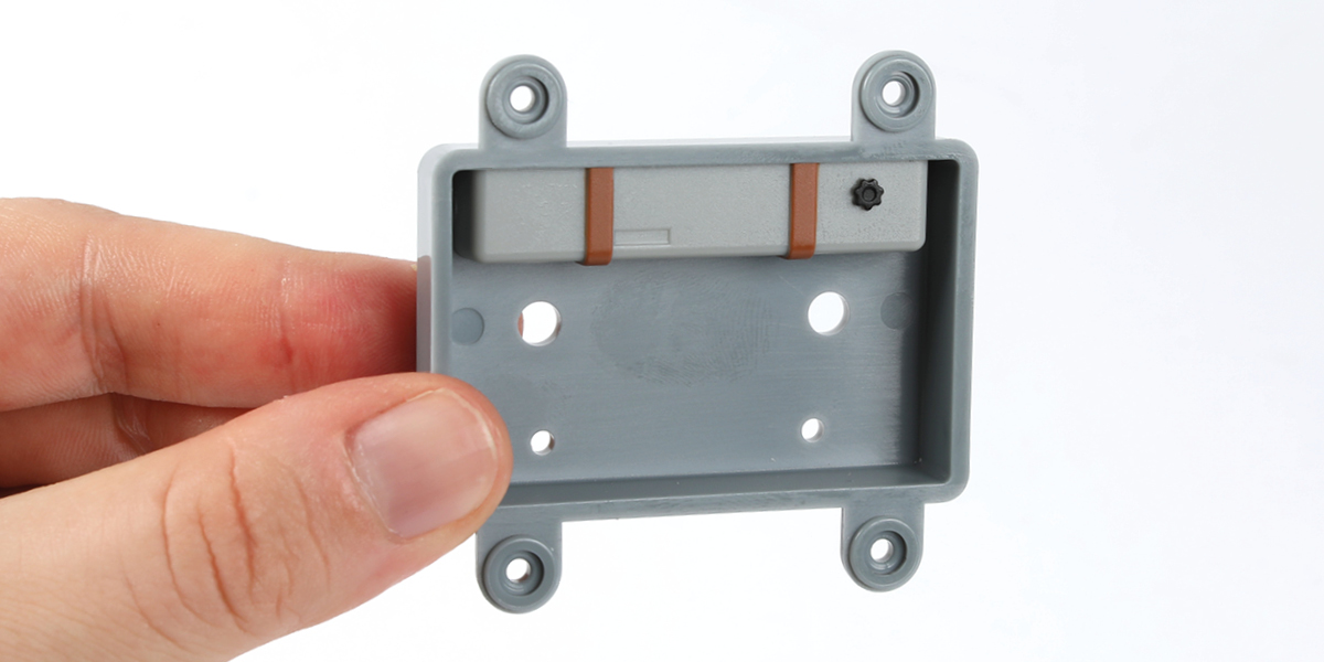
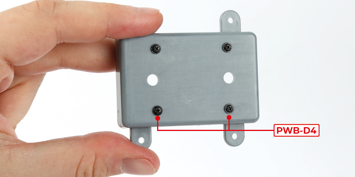
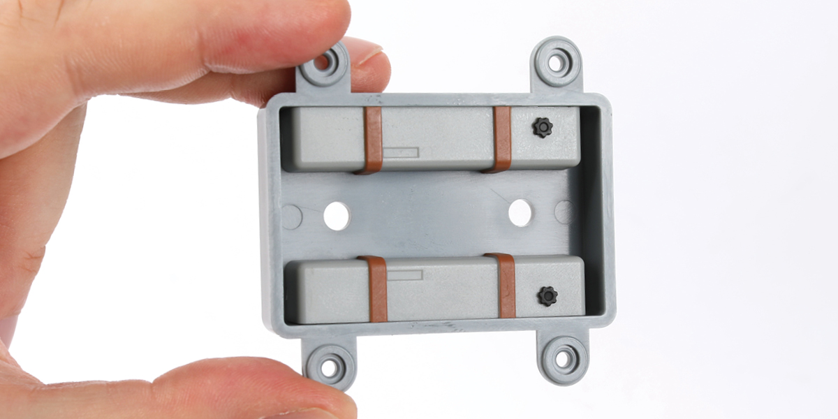
Attach part 21-M to part 21-D using two PWB-D4 screws.
Step 3
Attach part 21-N to part 21-D using two PWB-D4 screws.
Step 4
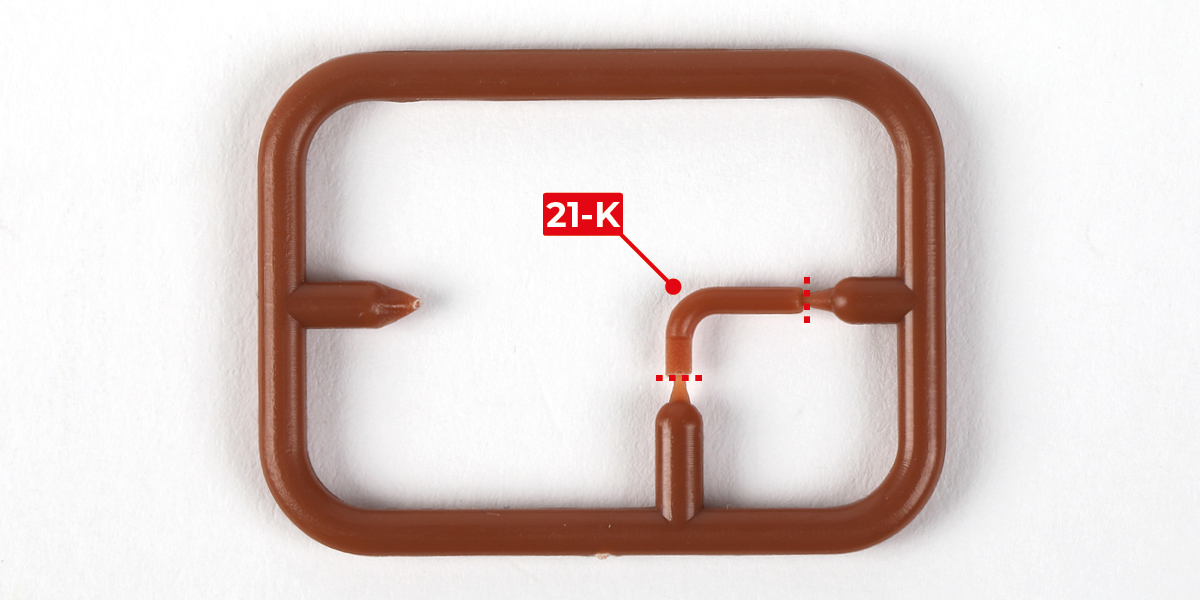
Cut part 21-K from the sprue.
Step 5
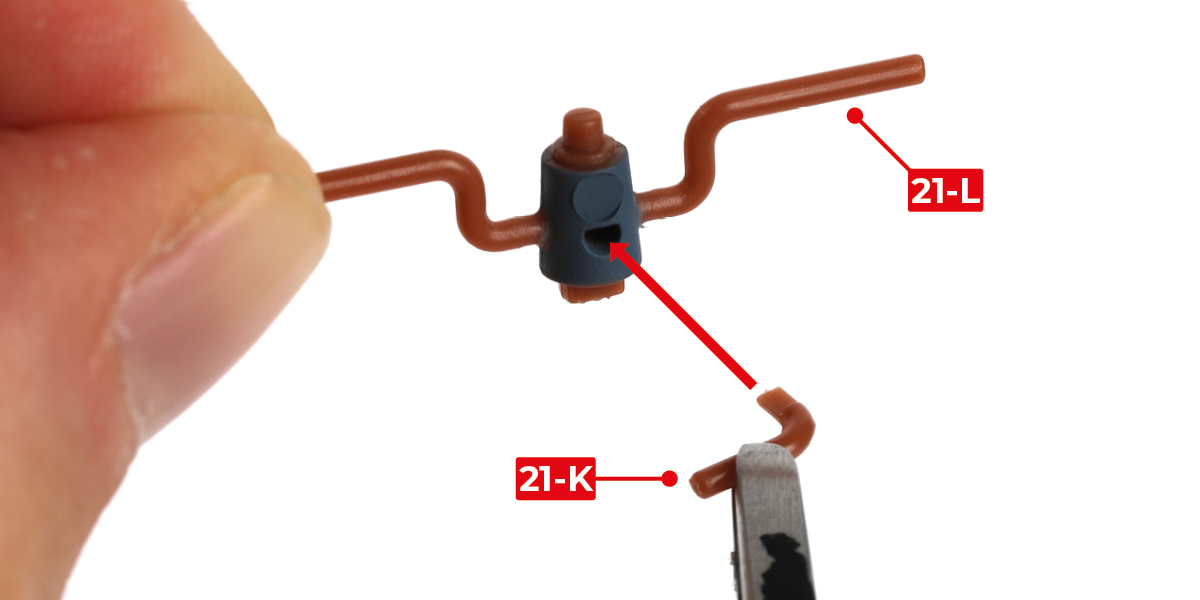
Glue part 21-K to part 21-L.
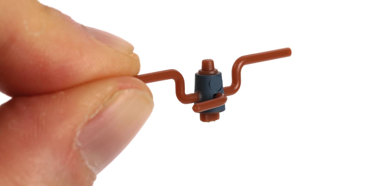
Step 6
Glue the assembly to part 21-E.
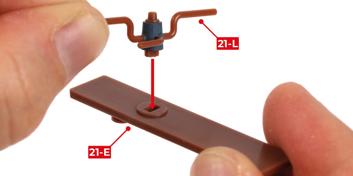
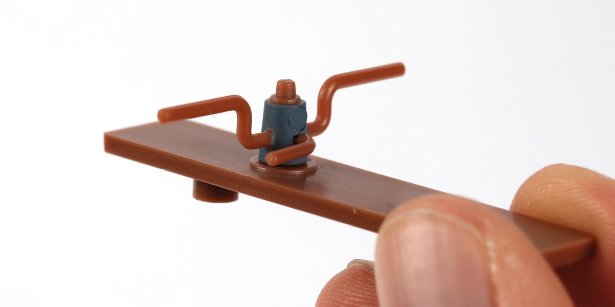
Step 7
Glue part 21-E to part 21-D, as shown.
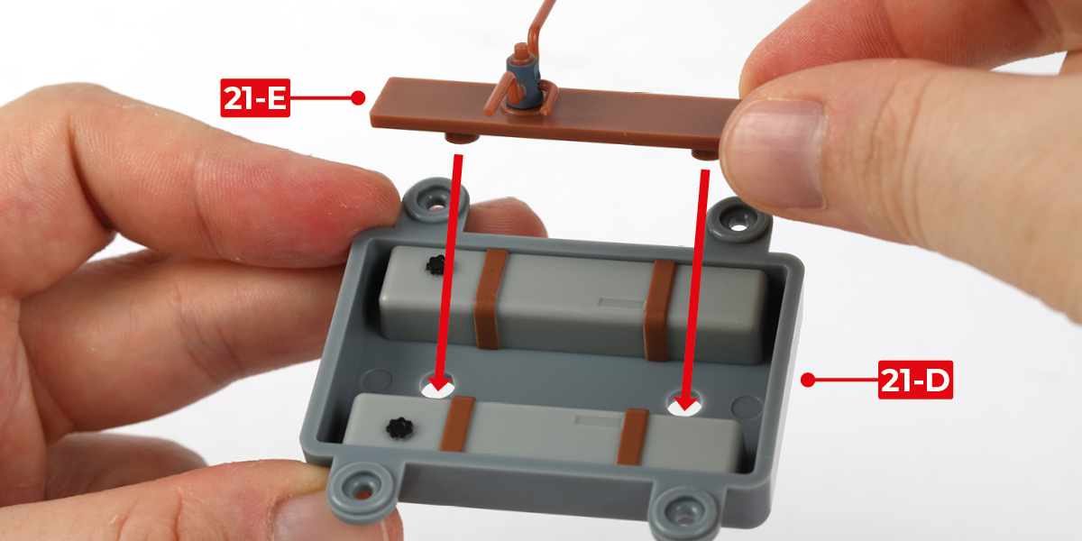
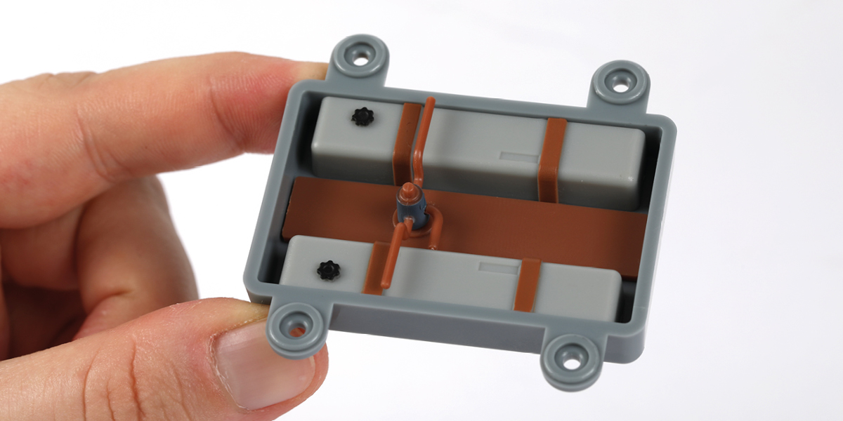
Step 8
Place part 21-G onto part 19-A.
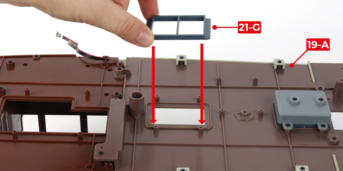
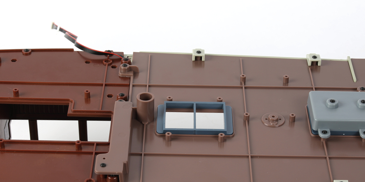
Step 9
Ensure the fuel tank assembly is in the orientation shown in image a. Secure the fuel tank assembly to part 19-A using four PWB-D4 screws.
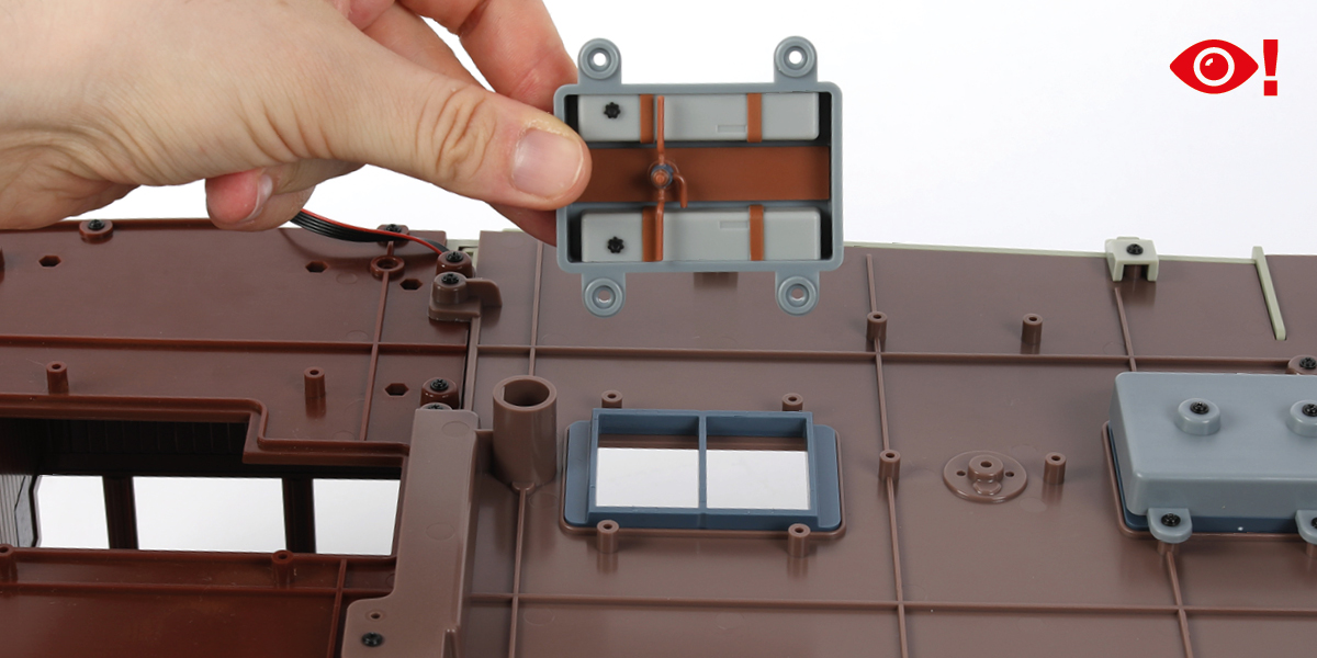
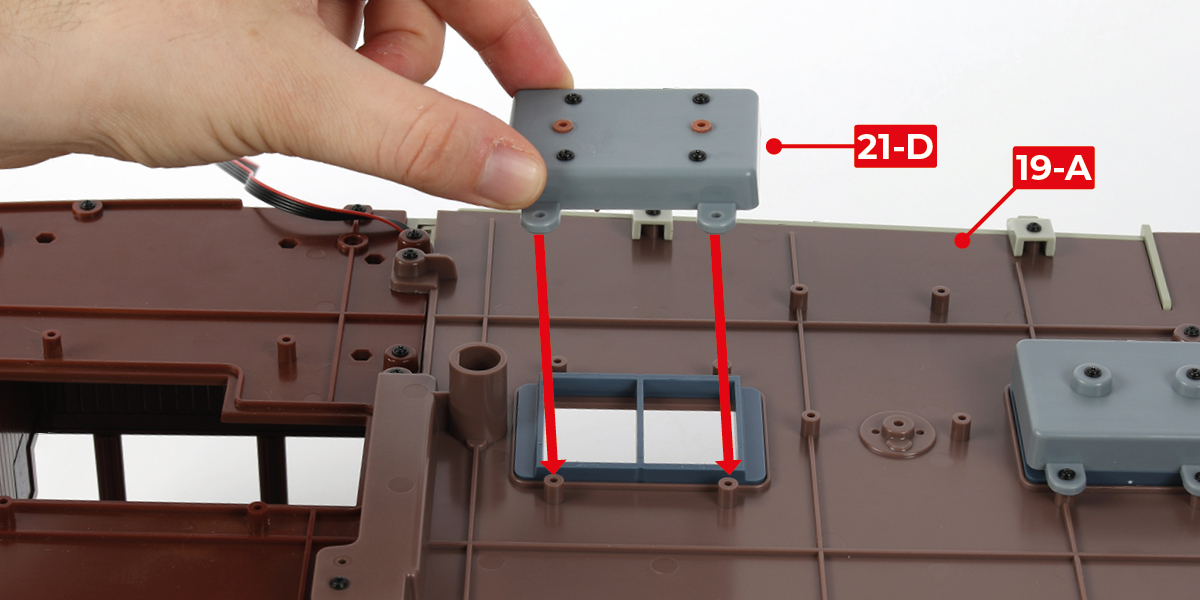
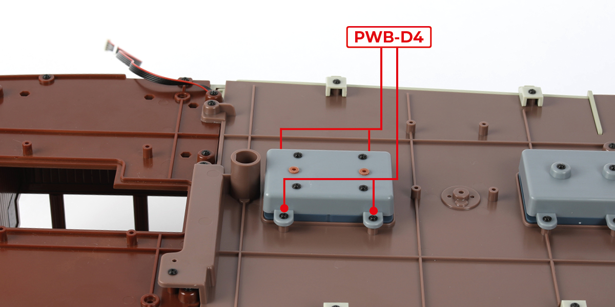
STAGE COMPLETE
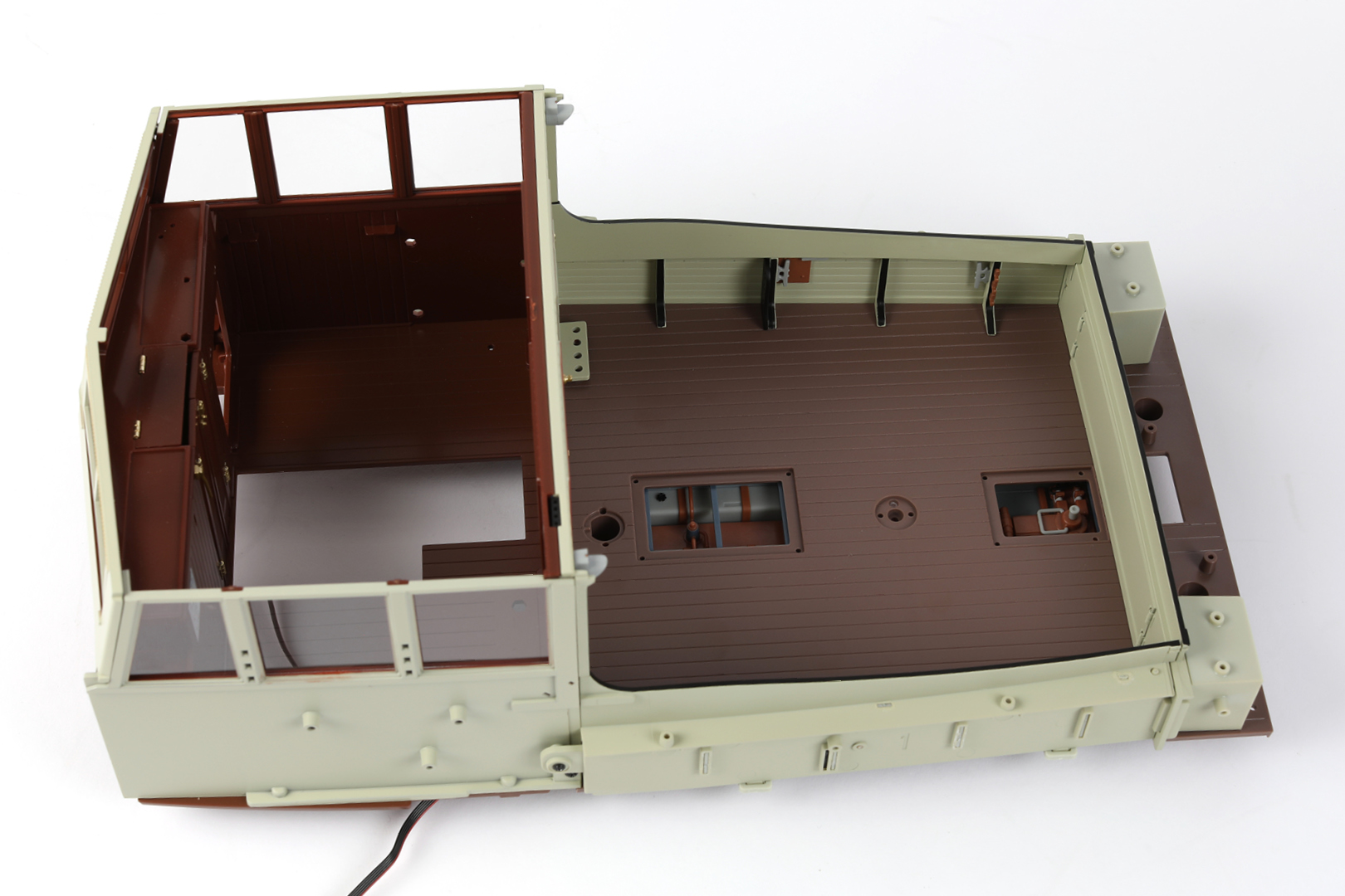
Step 1
Glue part 21-S to part 21-P.
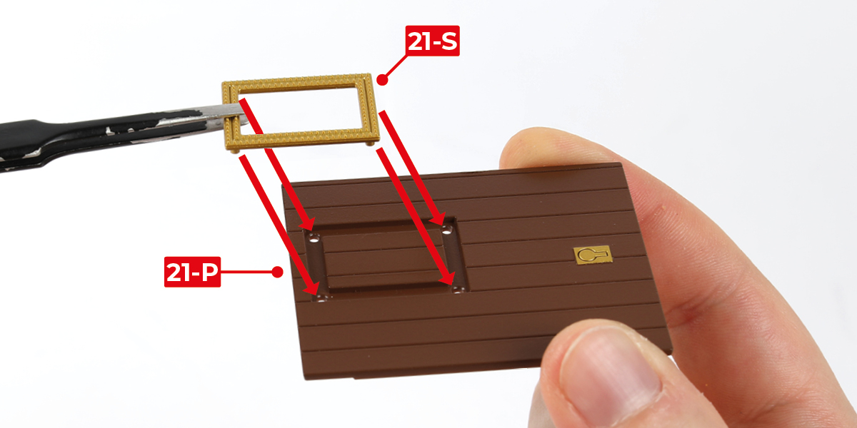
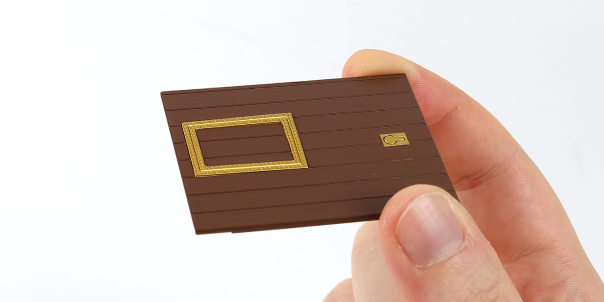
Step 2
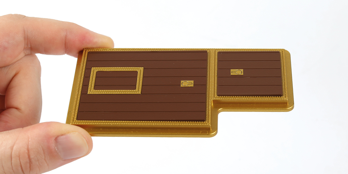
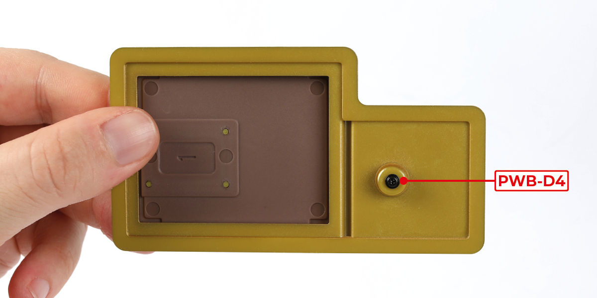
Place part 21-P onto part 22-B. Do not glue.
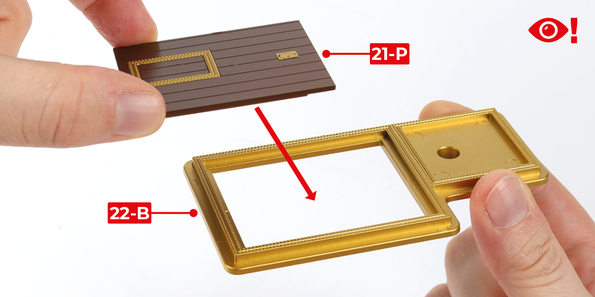
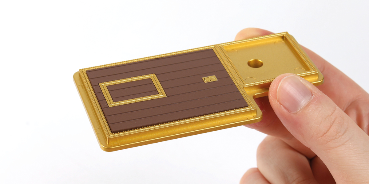
Step 3
Attach part 21-Q to part 22-B using one PWB-D4 screw.
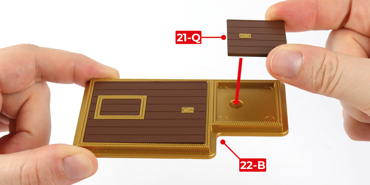
Step 4
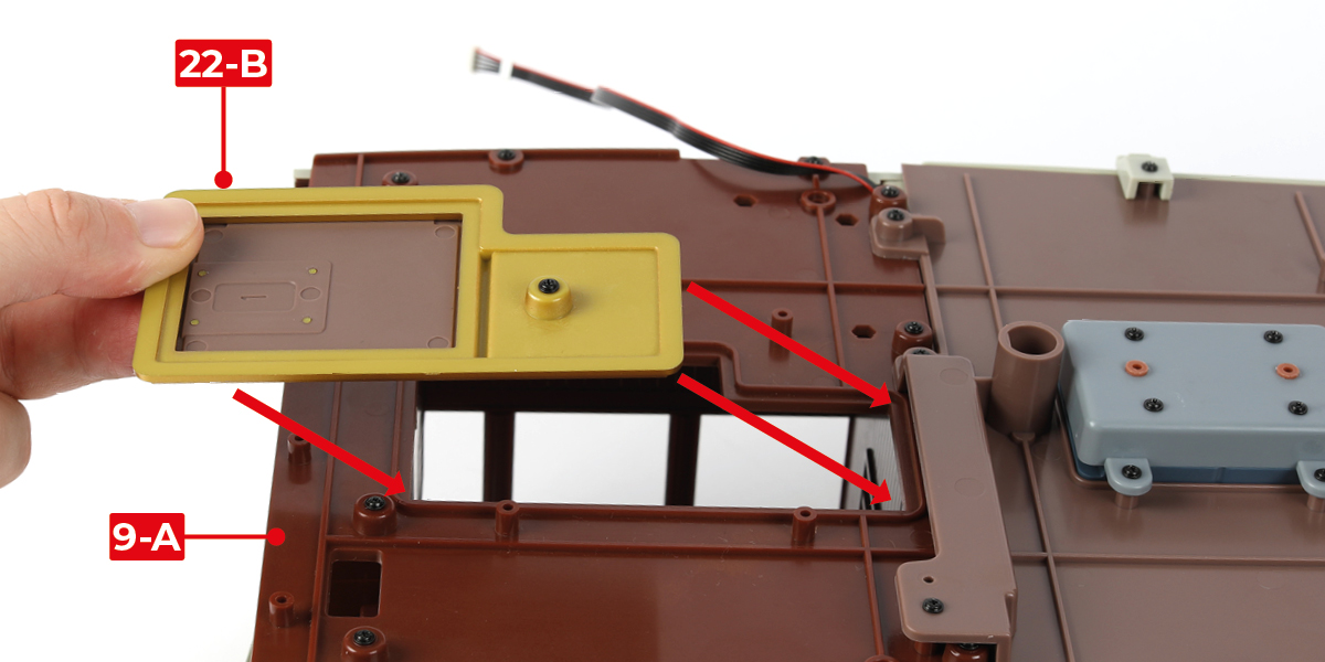
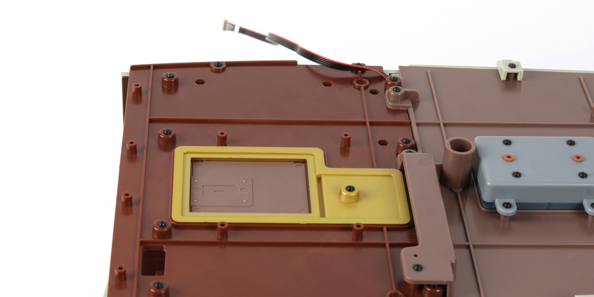
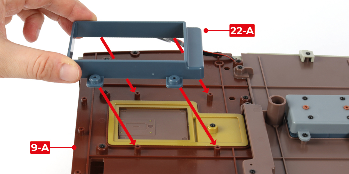
Place the hatches onto part 9-A.
Step 5
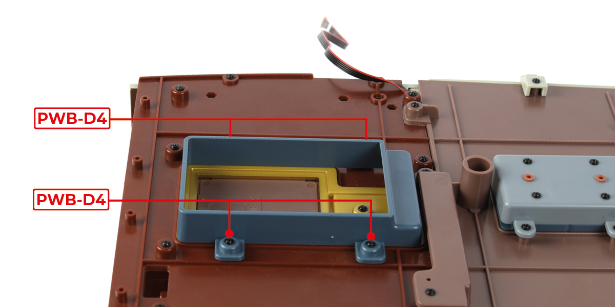
Attach part 22-A to part 9-A using four PWB-D4 screws.
Step 6
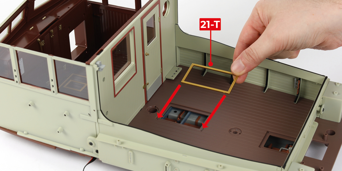
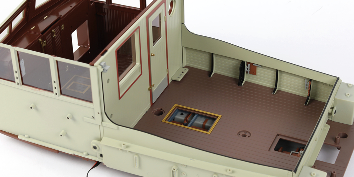
Turn the assembly over, then glue part 21-T to the aft deck, as shown.
Step 7
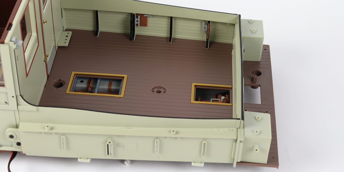
Glue part 21-R to the aft deck.
Step 8
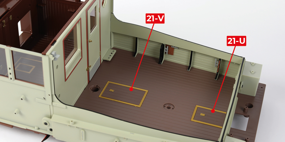
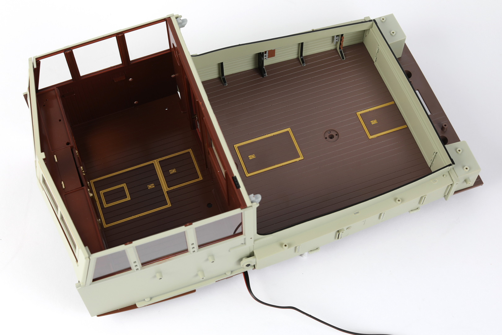
Place parts 21-V and 21-U into the frames, as shown. Do not glue.
STAGE COMPLETE
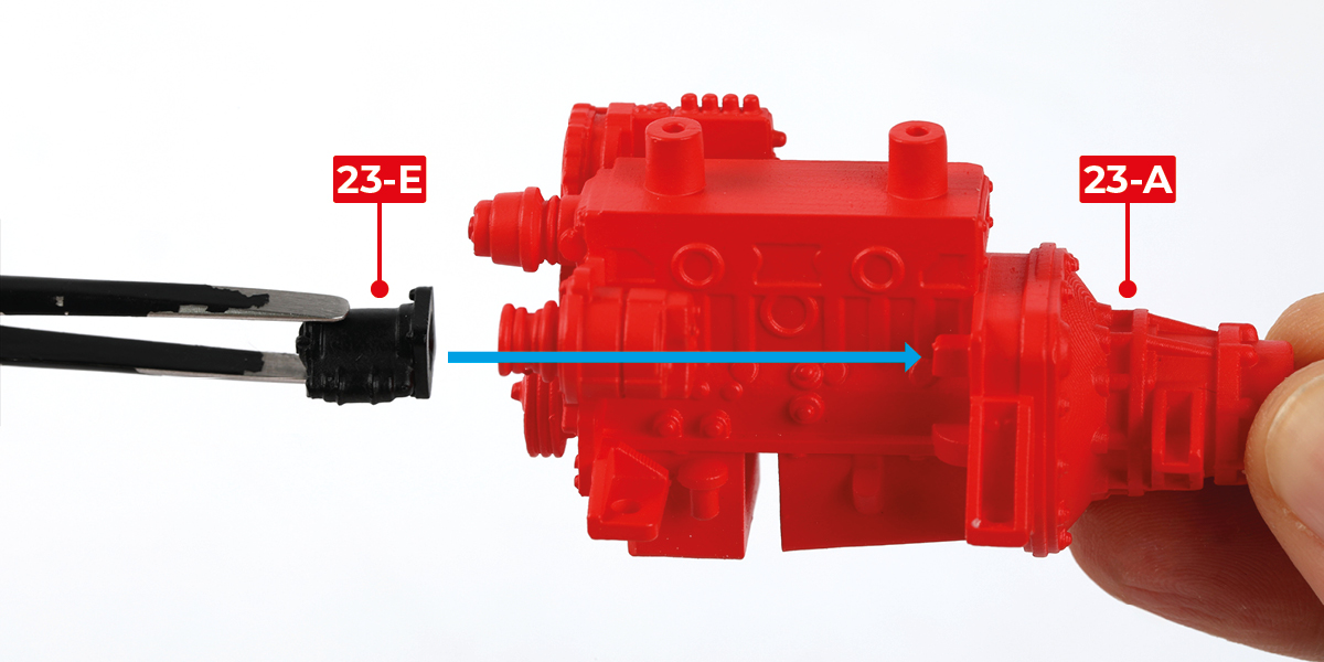
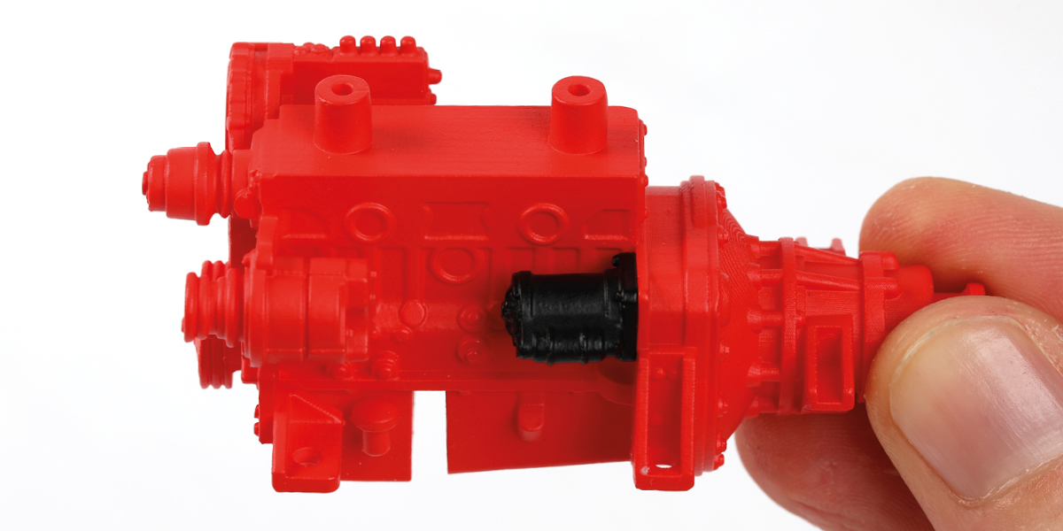
Step 1
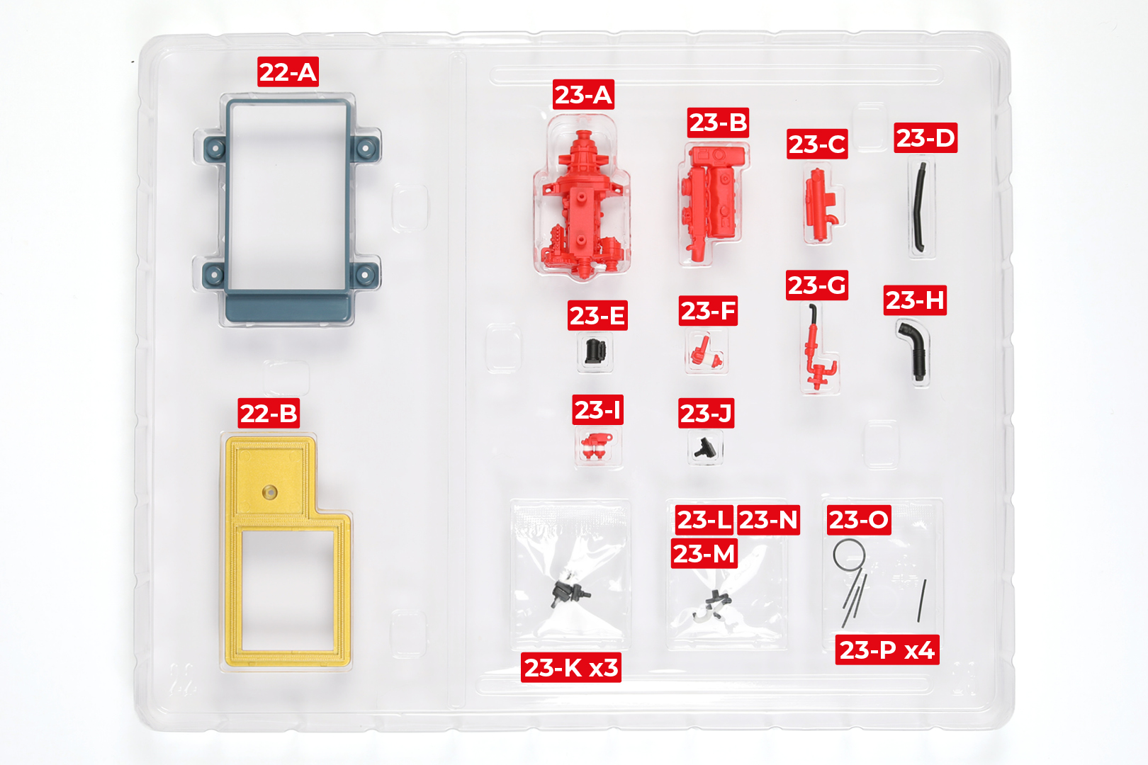
Glue part 23-E to part 23-A.
Step 2
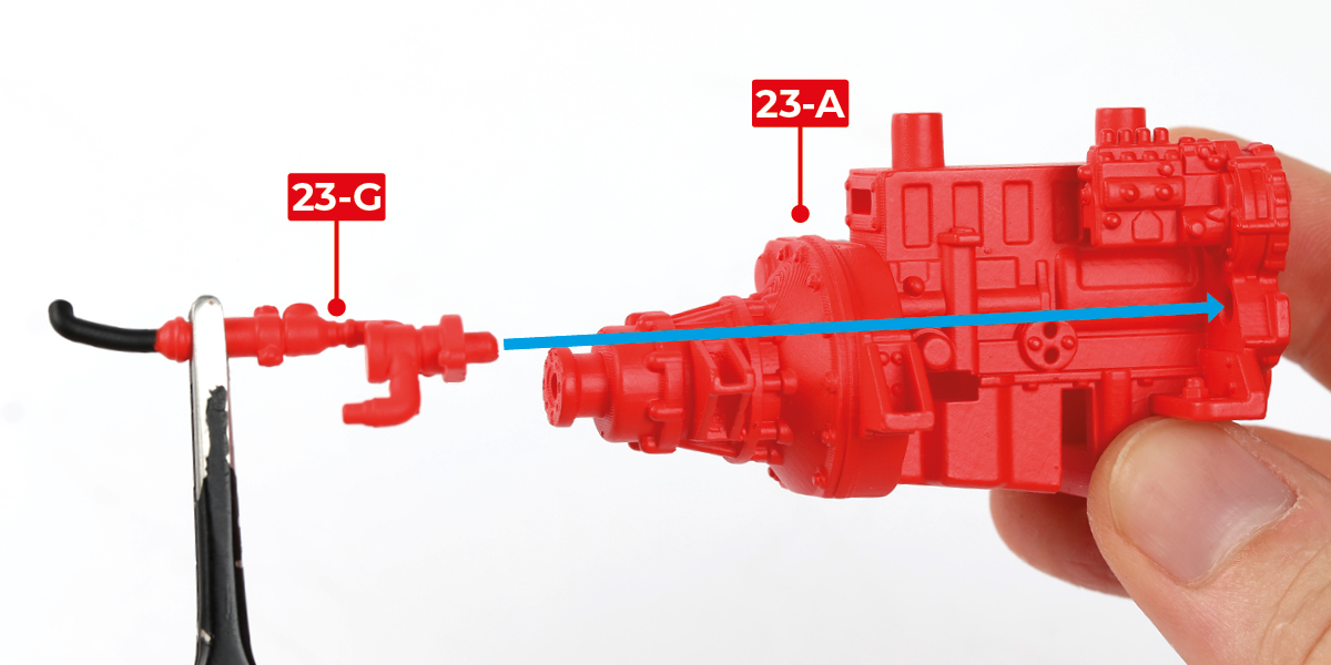
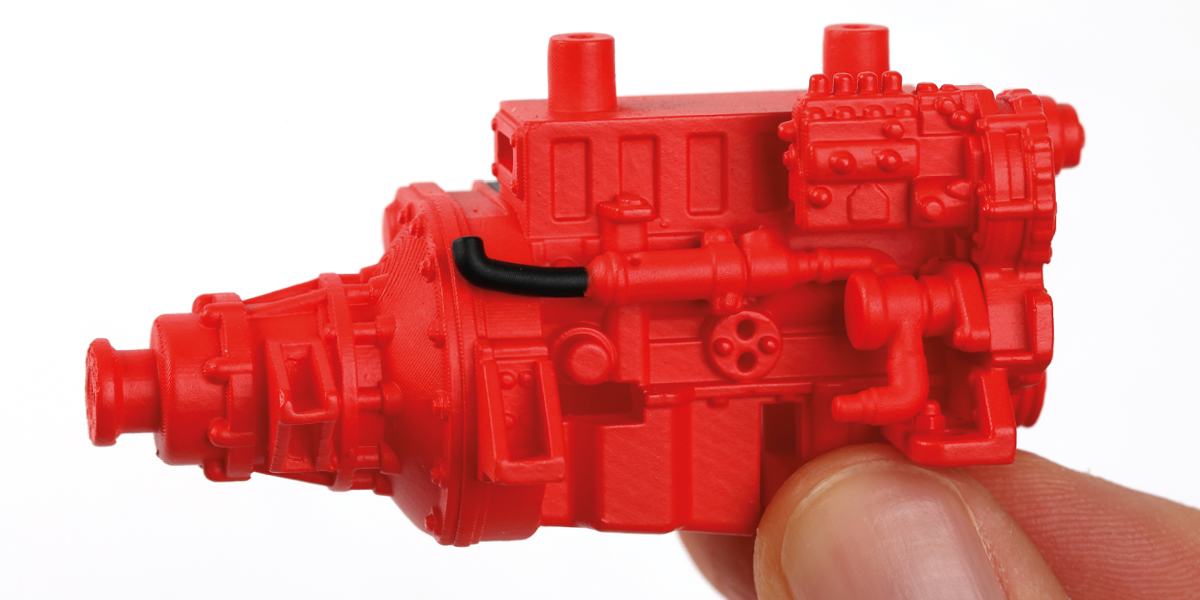
Glue part 23-G to part 23-A.
Step 3
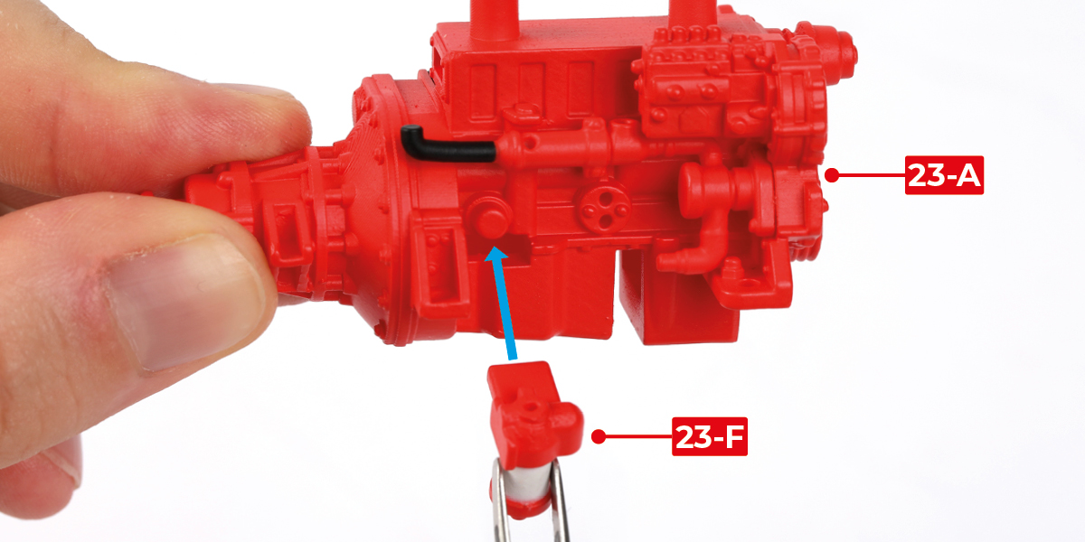
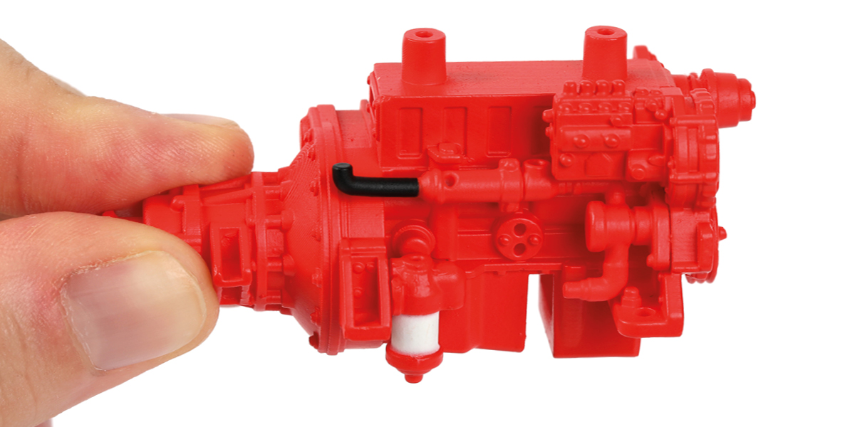
Glue part 23-F to part 23-A.
Step 4
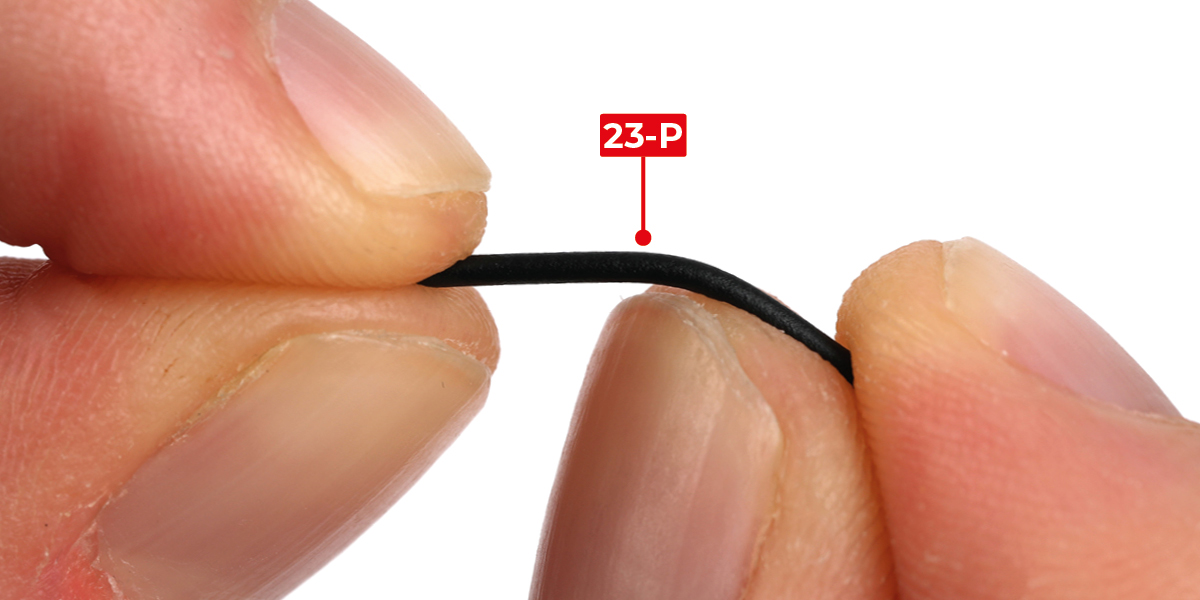
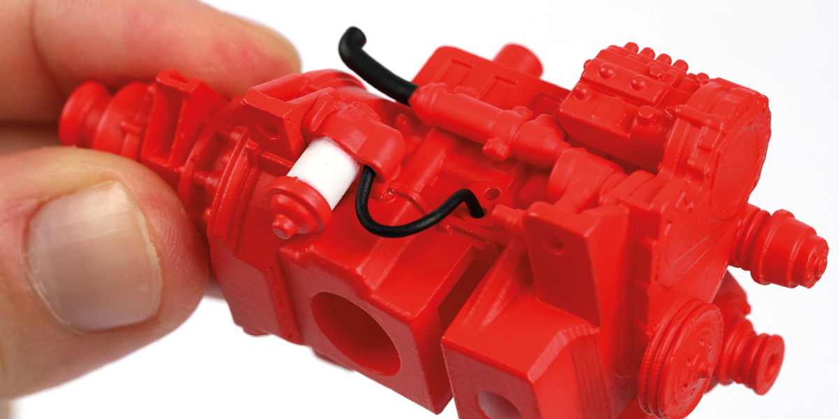
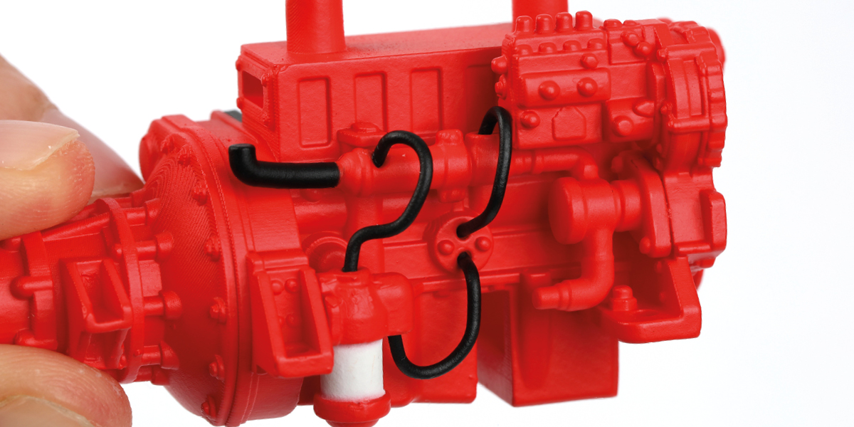
Bend the first part 23-P into shape. Glue part 23-P to the engine assembly.
Step 5
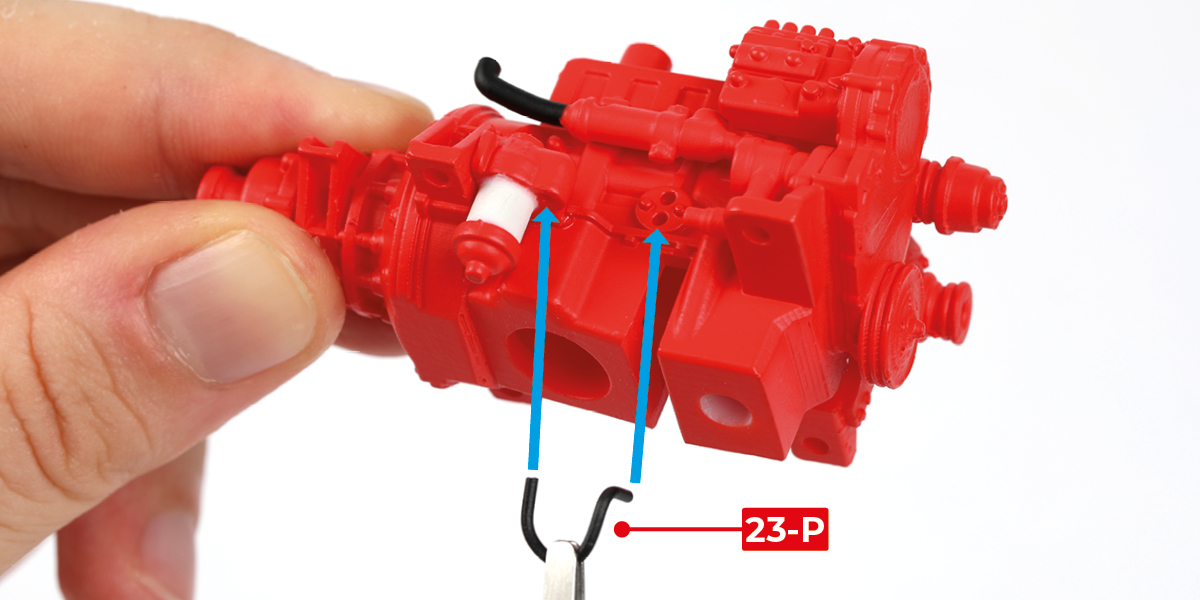
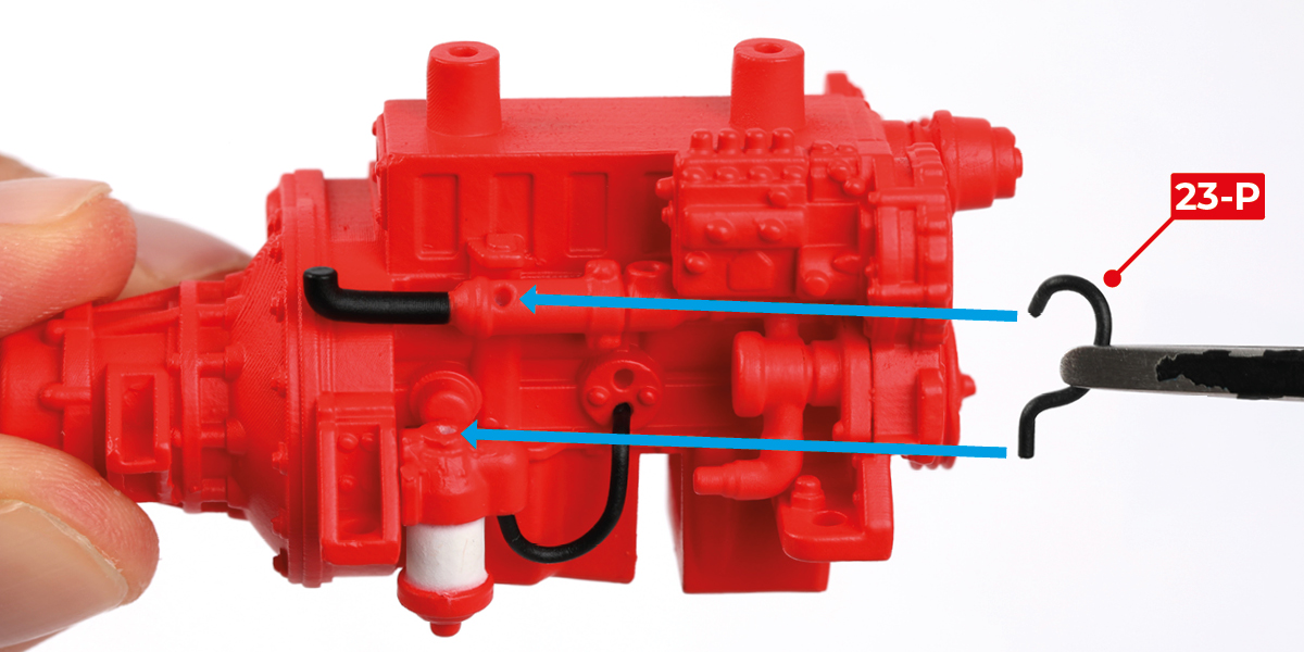
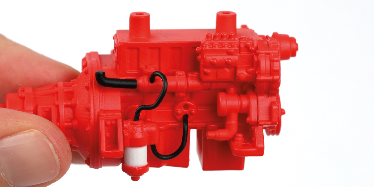
Bend a second part 23-P into shape. Glue part 23-P to the engine assembly.
Step 6
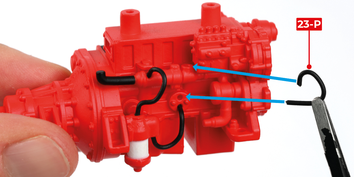
Bend a third part 23-P into shape. Glue part 23-P to the engine assembly.
Step 7
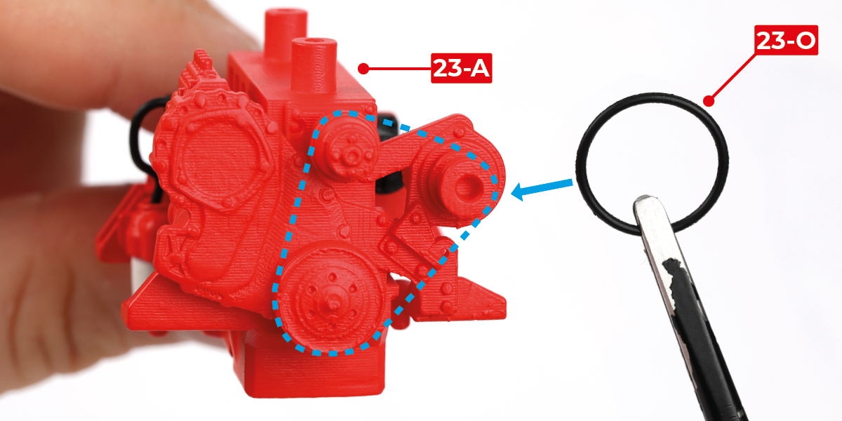
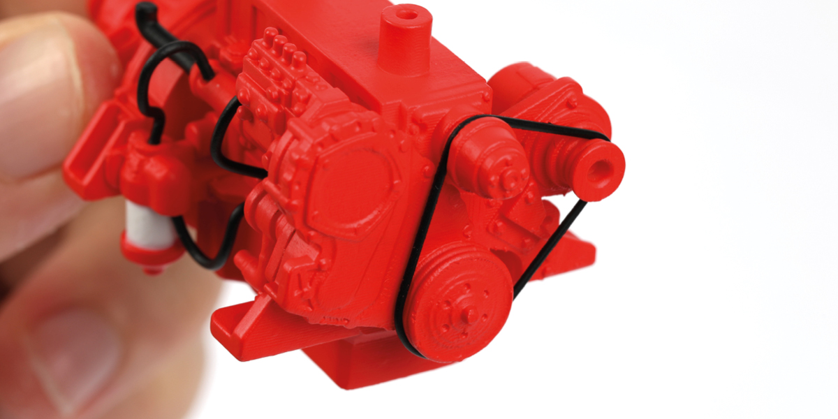
Position part 23-O as shown.
STAGE COMPLETE
Step 1
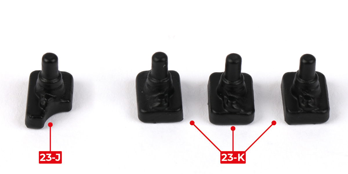
Identify parts 23-J and 23-K.
Step 2
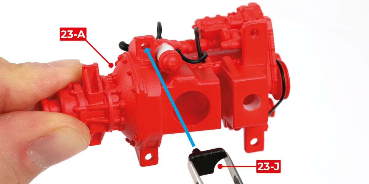
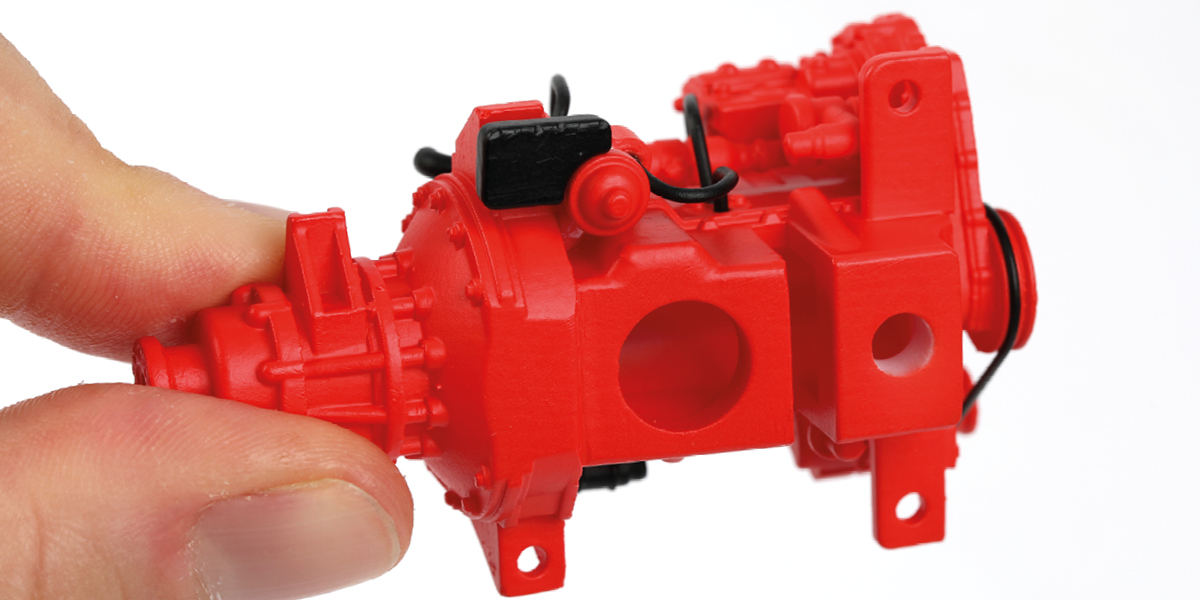
Glue part 23-J to the engine assembly.
Step 3
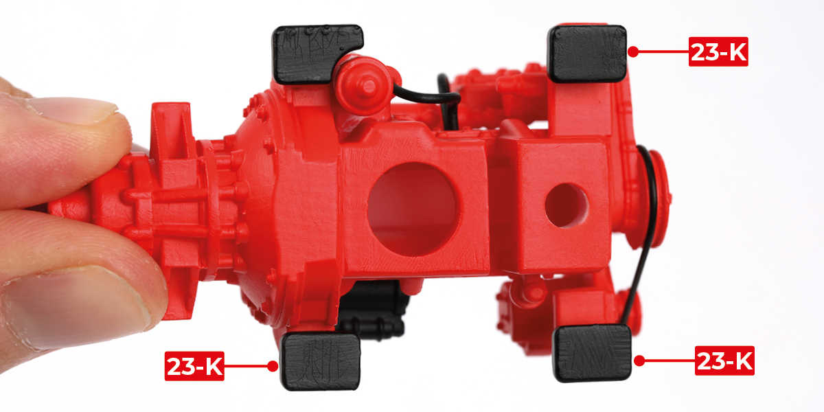
Glue parts 23-K to the engine assembly.
Step 4
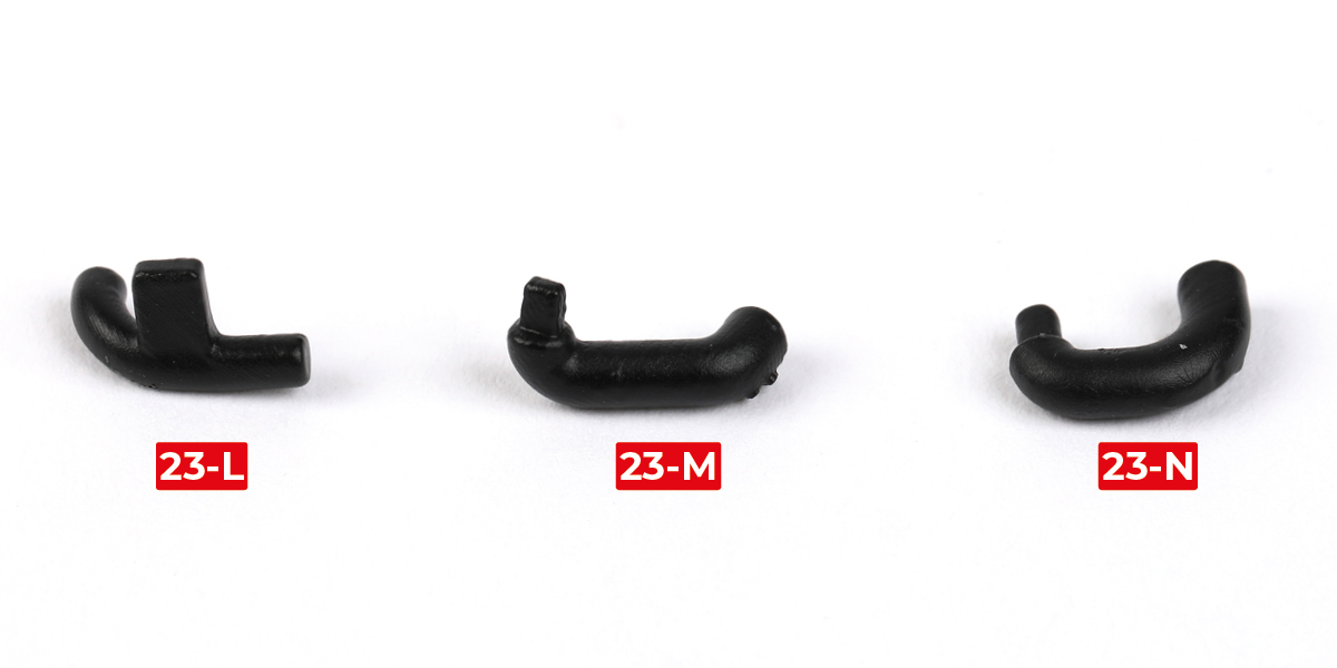
Identify parts 23-L, 23-M and 23-N.
Step 5
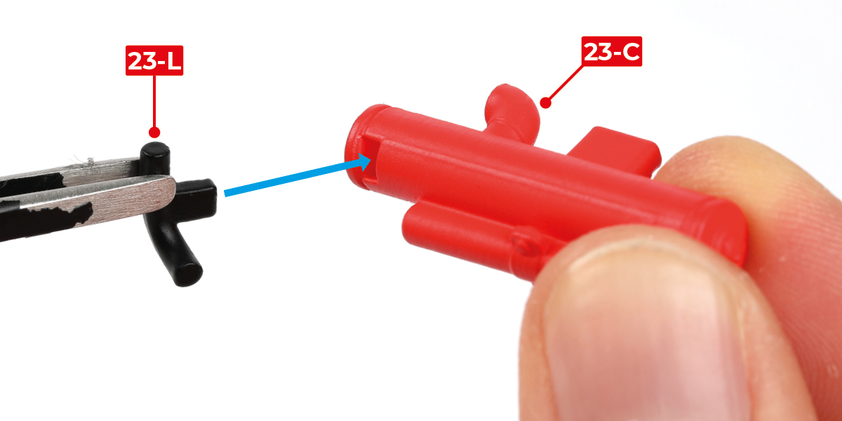
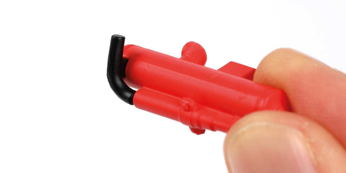
Glue part 23-L to part 23-C.
Step 6
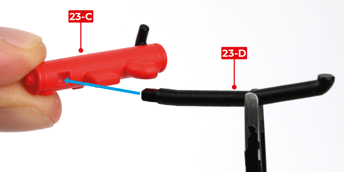
Glue part 23-D to part 23-C.
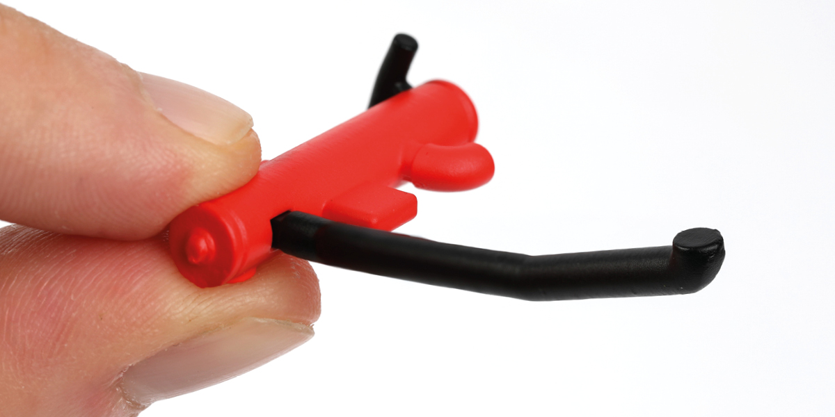
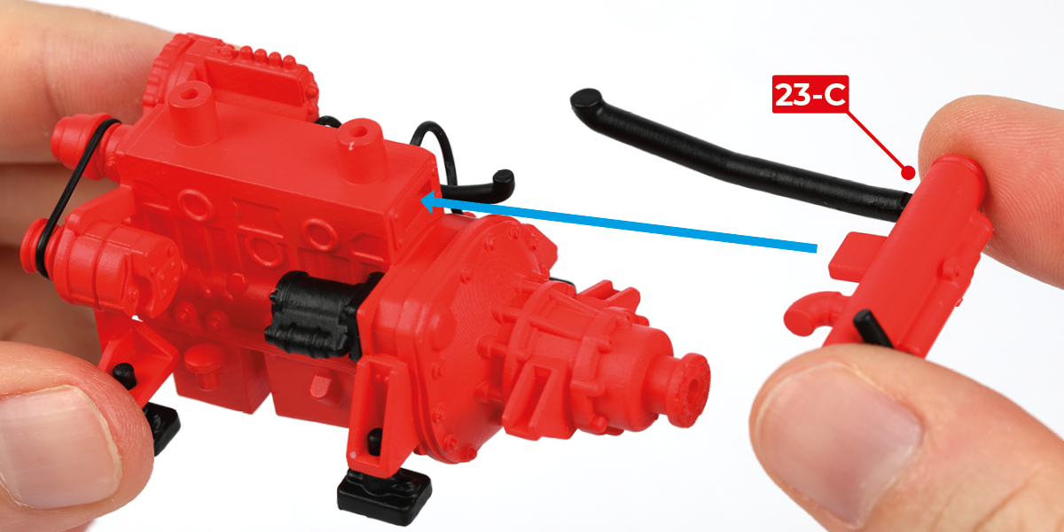
Step 7
Glue part 23-C to the engine assembly.
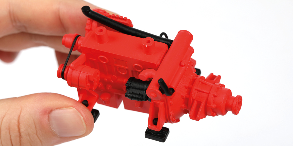
STAGE COMPLETE
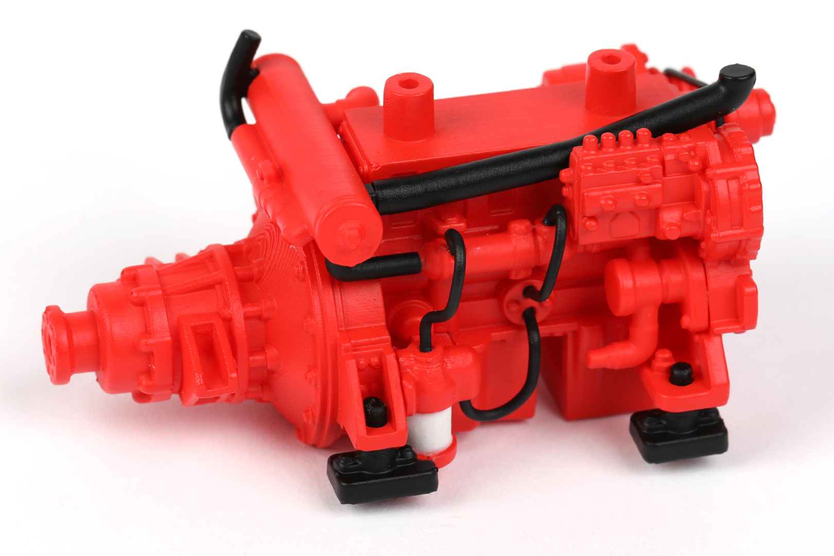
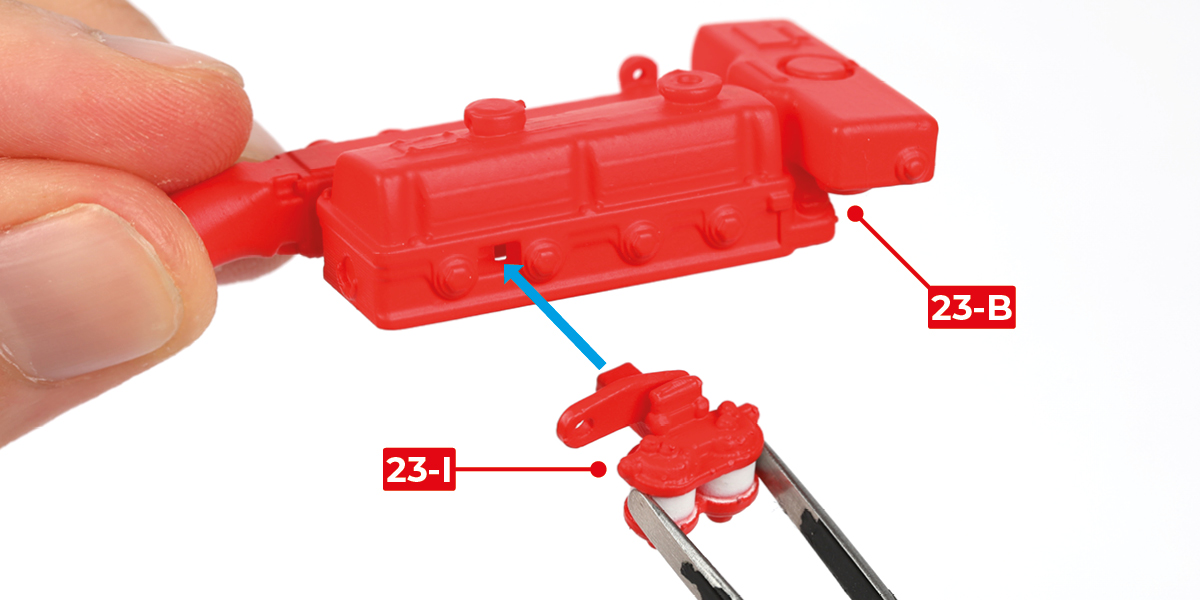
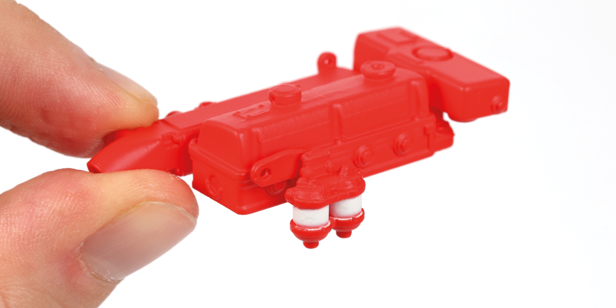
Step 1
Glue part 23-I to part 23-B.
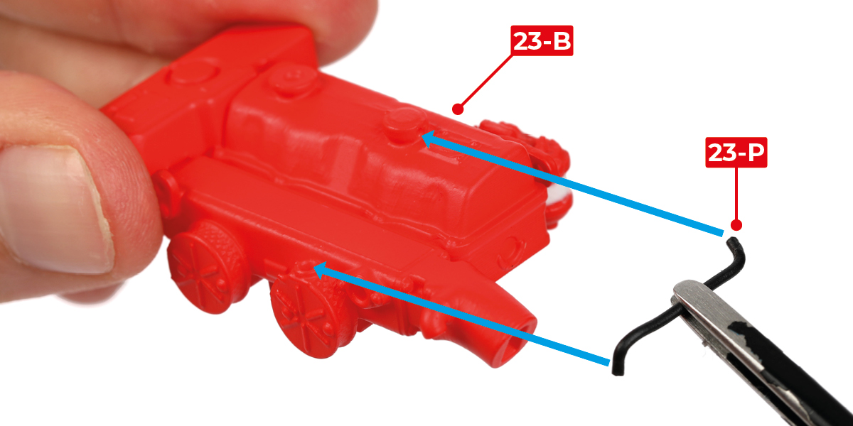
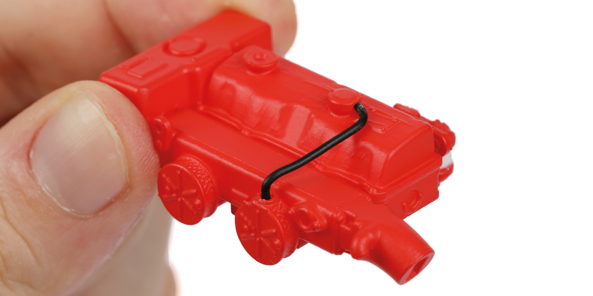
Step 2
Bend the last part 23-P into shape. Glue part 23-P to the assembly.
Step 3
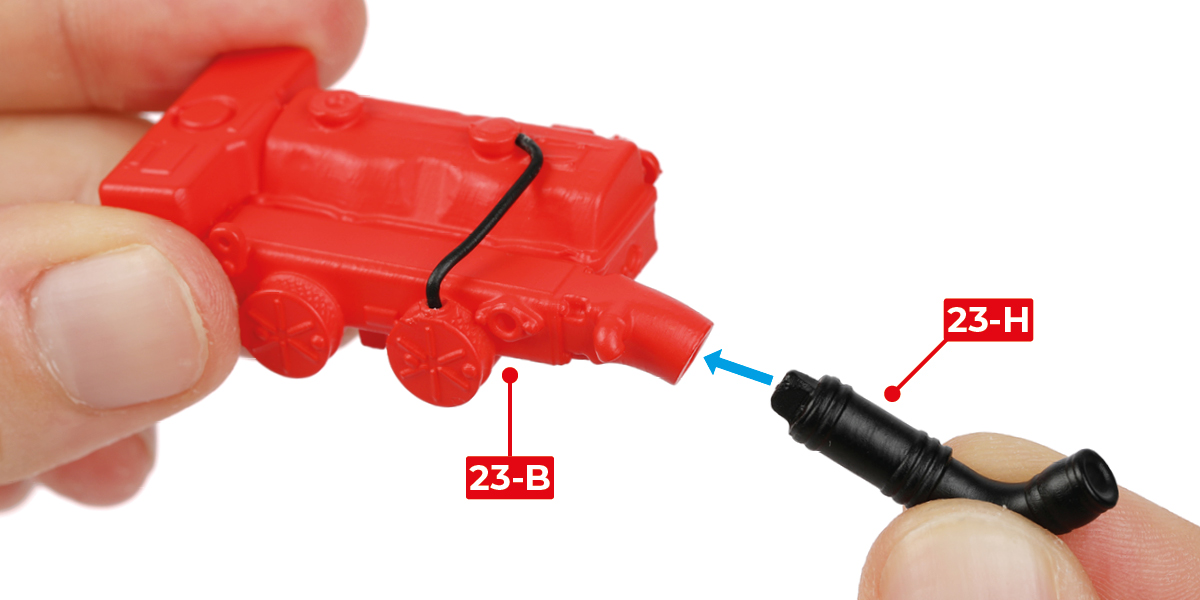
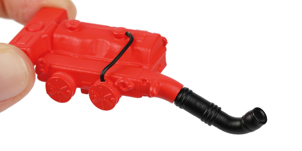
Glue part 23-H to the assembly.
Step 4
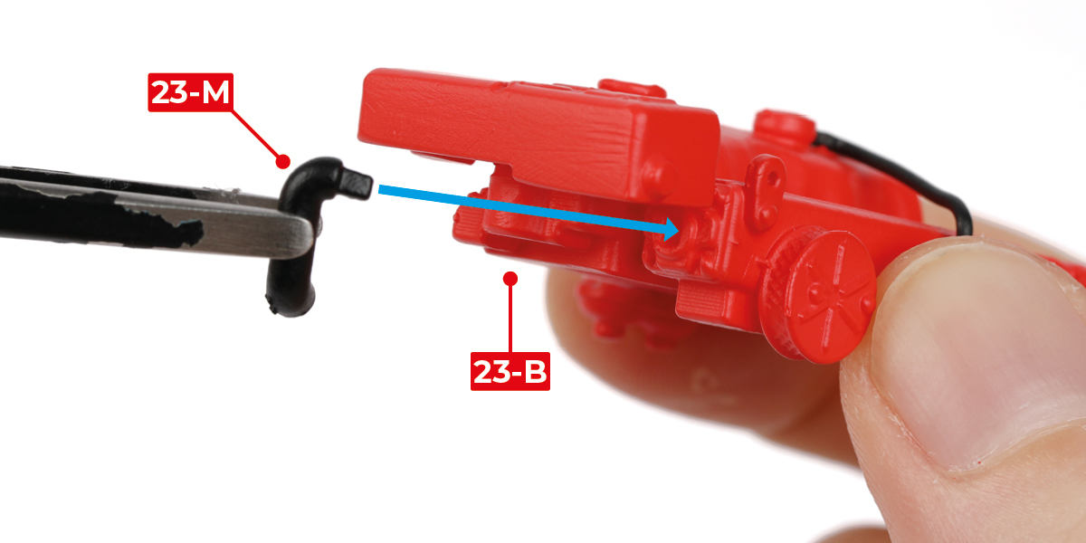
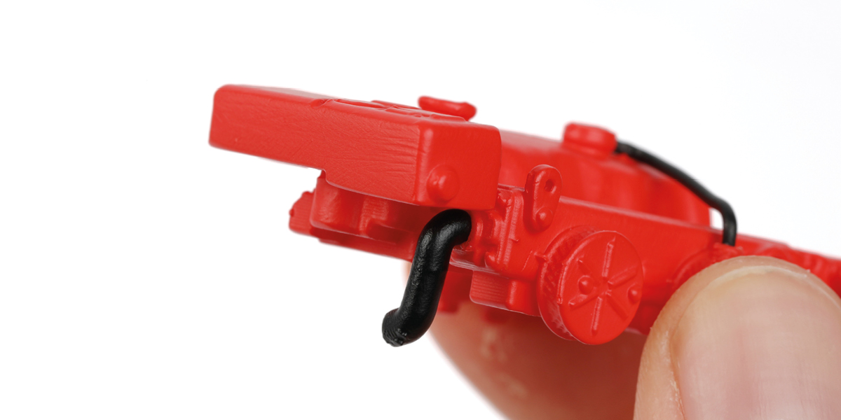
Glue part 23-M to the assembly.
Step 5
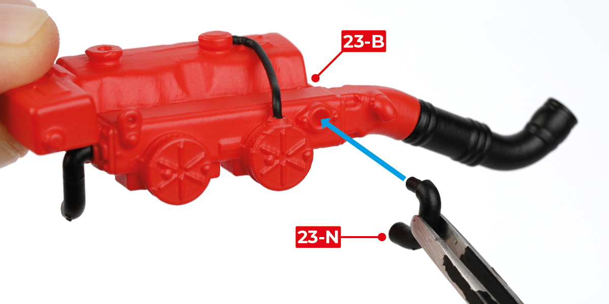
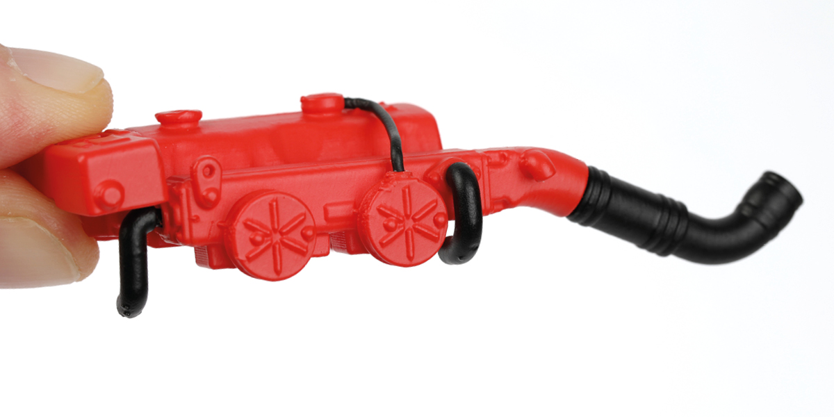
Glue part 23-N to the assembly.
Step 6
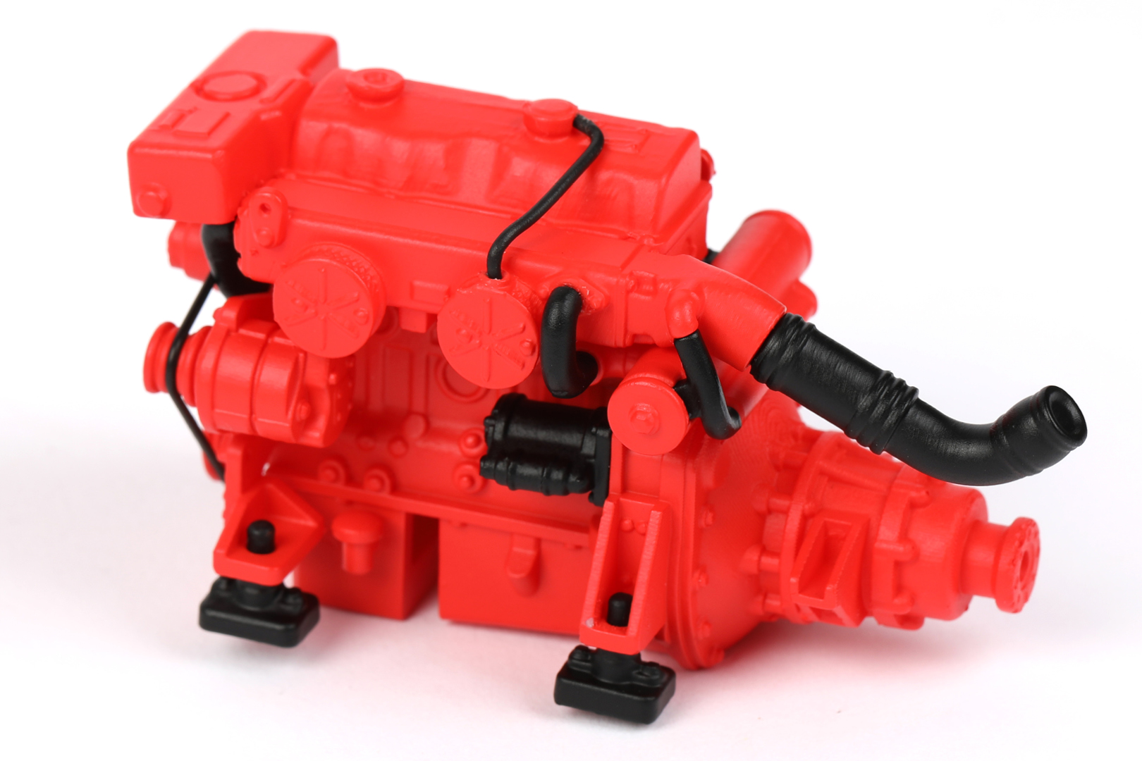
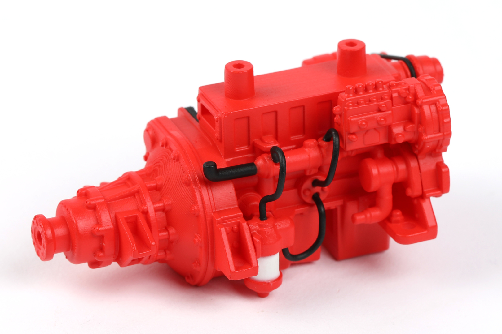
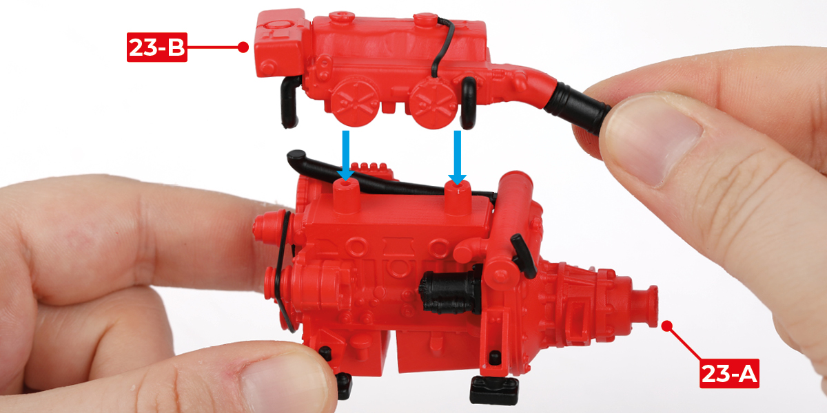
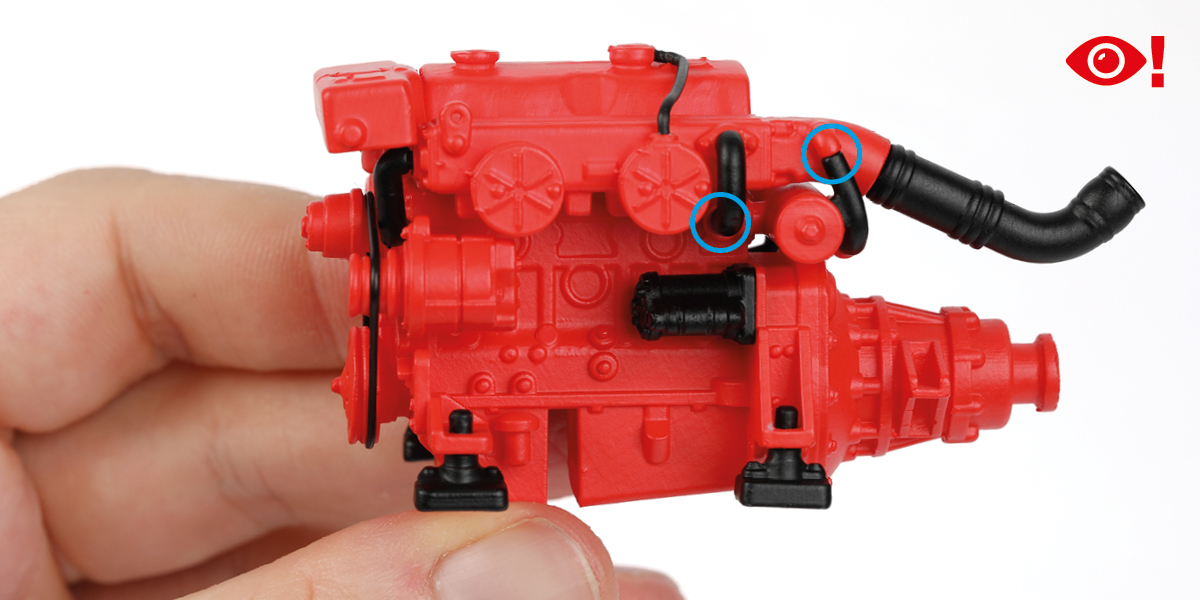
Glue the two engine assemblies together. Ensure that the pipes are positioned correctly, as shown by the blue circles in images b and c.
STAGE COMPLETE