Pack 11
BUILD INSTRUCTIONS
Advice from the experts
Spare screws are included with each part. Occasionally, you may be instructed to keep spare or unused screws for a later stage. Keep these spares in a safe place and label them correctly.
Please make sure you don’t mix up the screws. They look quite similar, but the threads do vary slightly. Using the wrong screws may damage the parts. Only use the correct size screwdriver that fits the screw head firmly.
When securing parts together using multiple screws, fit each screw loosely to ensure all the parts are correctly aligned before gently tightening them firmly, but not overtight, in the order in which you placed them.
The screwdriver can be magnetized by stroking it with a magnet (fridge magnet, etc.) enabling it to hold the screws and make assembly easier.
If a screw is tight going into a metal part, do not force it as you may shear the head off. Remove it and put a tiny smear of Vaseline, soap or light oil on the thread. That will lubricate it and make it easier to tighten.
Some parts will require a little glue for assembly. Please apply glue sparingly and use a cocktail stick so that you don’t use too much nor apply the glue too heavily. We recommend superglue gel or Extra Thin Liquid modeling glue. Where possible, parts should be test-fitted in place before gluing.
Make sure you have good ventilation when using adhesives and to replace caps firmly.
Use a magnet to help find screws that have fallen on the floor.
Use masking tape to hold parts temporarily in place.
Cut parts from a sprue (framework) with side cutters or a craft knife. Side cutters tend to be easiest.
During the course of this build, you will receive many pieces that you will assemble immediately – following the instructions in the corresponding stage – and other pieces that you should store safely to one side, for use in future assembly stages.
Always protect the paint finish on components by placing a cutting mat, sheet of white paper or soft cloth on your work surface.
When plugging cables in, ensure the power is switched off. Tweezers can be used to fit the PVC cables by gripping carefully around 5mm from the end of the cable. If a cable needs to be removed from a socket, do not pull on the cable as this could damage the connection. Grip the plug with tweezers to remove it.
Left and Right! When building your Goldfinger DB5, the left- or right-hand side refers to that side as if you are sitting in the car.
![]() When you see this symbol, pay attention to the instruction text in bold and check the orientation of the parts in the image as this will be particularly important for assembly in later stages.
When you see this symbol, pay attention to the instruction text in bold and check the orientation of the parts in the image as this will be particularly important for assembly in later stages.
WARNING: Some parts are assembled using magnets. These magnets can cause serious injury if they are swallowed. Keep away from children. If you suspect a magnet has been swallowed, seek medical help straight away.
This is not a toy. Not suitable for children under 14 years old due to small parts. Adult supervision required.

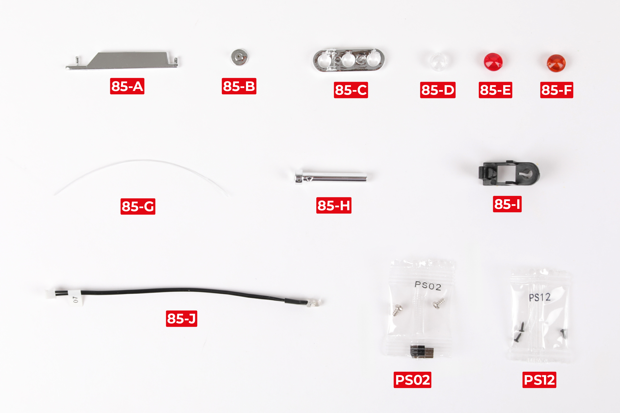
PARTS LIST
| 85-A Side strake | 85-G Nylon string |
| 85-B Cap | 85-H Oil slick jet |
| 85-C Rear light housing | 85-I Oil slick jet mount |
| 85-D Reverse light lens | 85-J Brake light LED |
| 85-E Brake light lens | 2x PS02 screws |
| 85-F Indicator light lens | 3x PS12 screws |
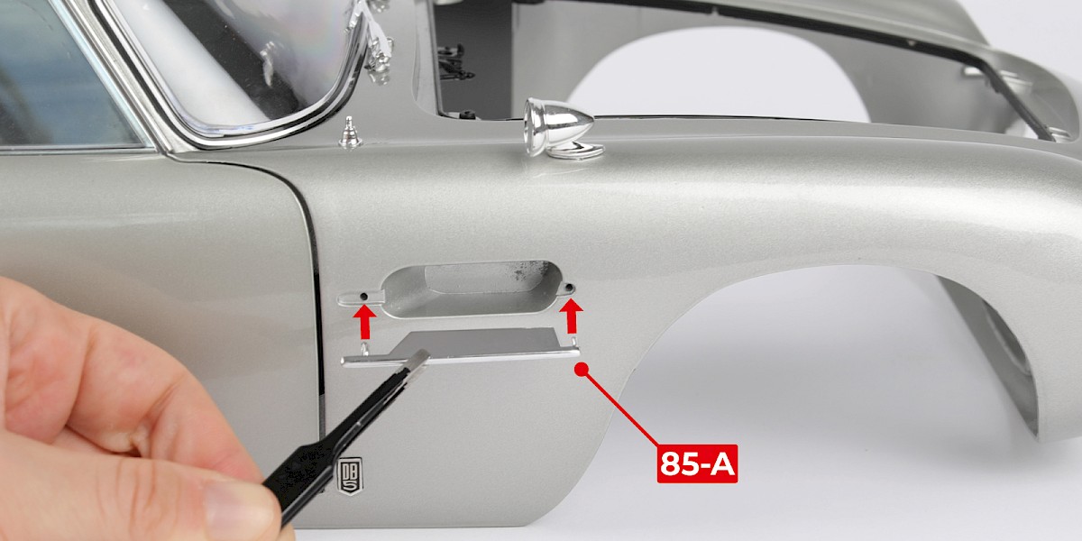
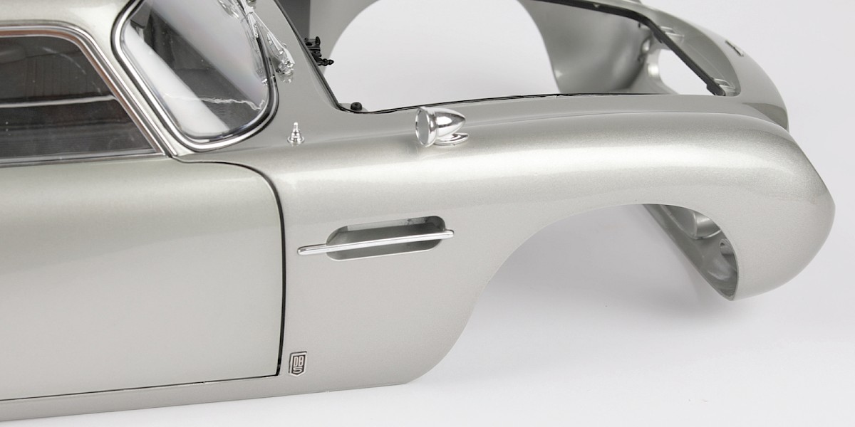
Step 1
Fit the side strake (85-A) on the right side of the main body (stage 84).
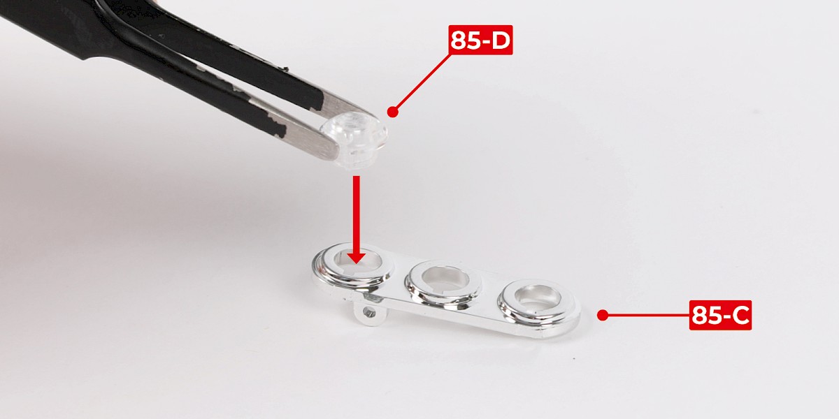
Step 2
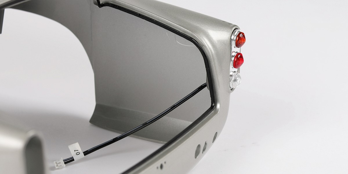
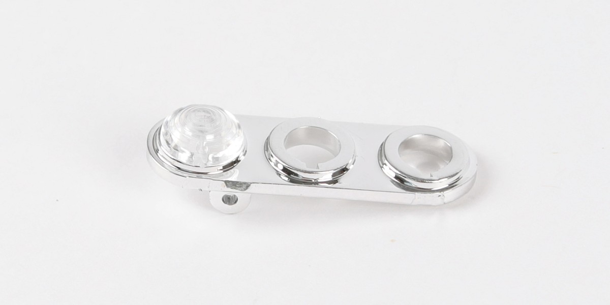
Fit the reverse light lens (85-D) into the rear light housing (85-C).

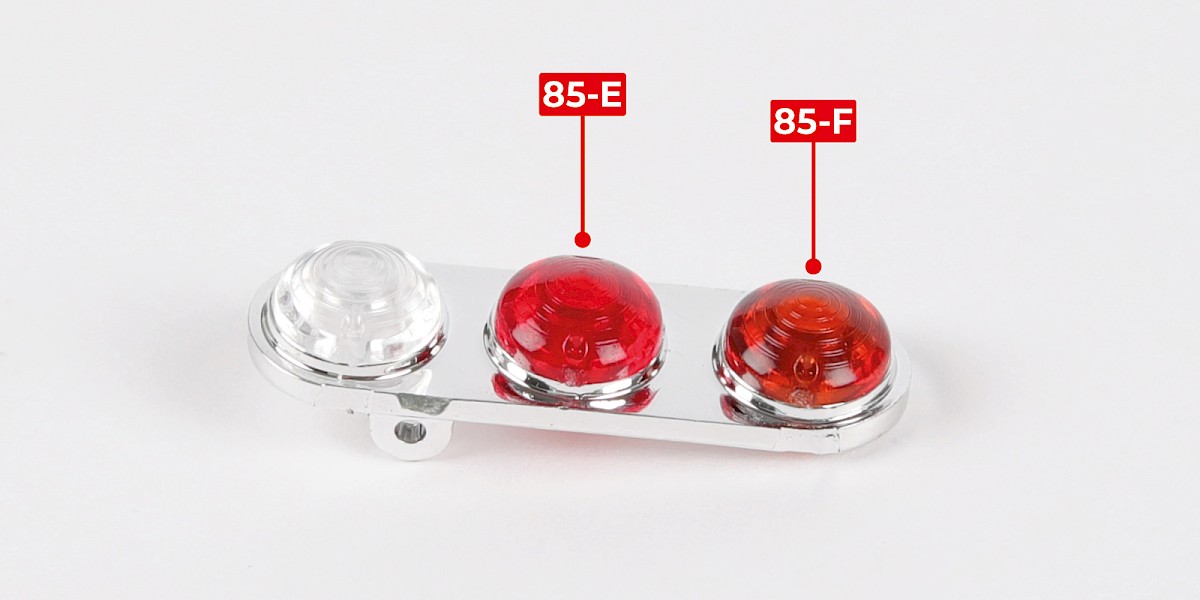
Step 3
Fit the brake light lens (85-E) and the indicator light lens (85-F) in place.
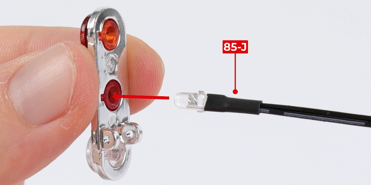
Step 4
Fit the brake light LED (85-J) into the brake light lens.
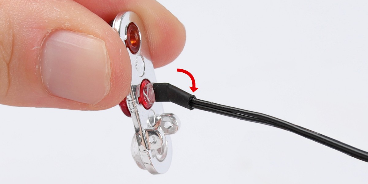
Bend the cable to the side.
Step 5
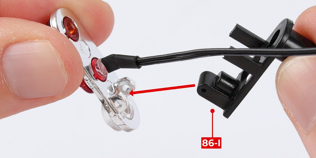
Fit the oil slick jet mount (85-I) to the assembly.
Secure with 1x PS12.


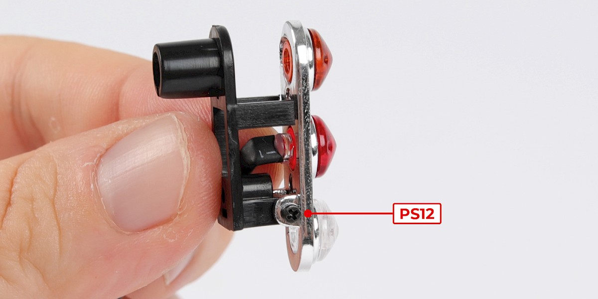
Step 6
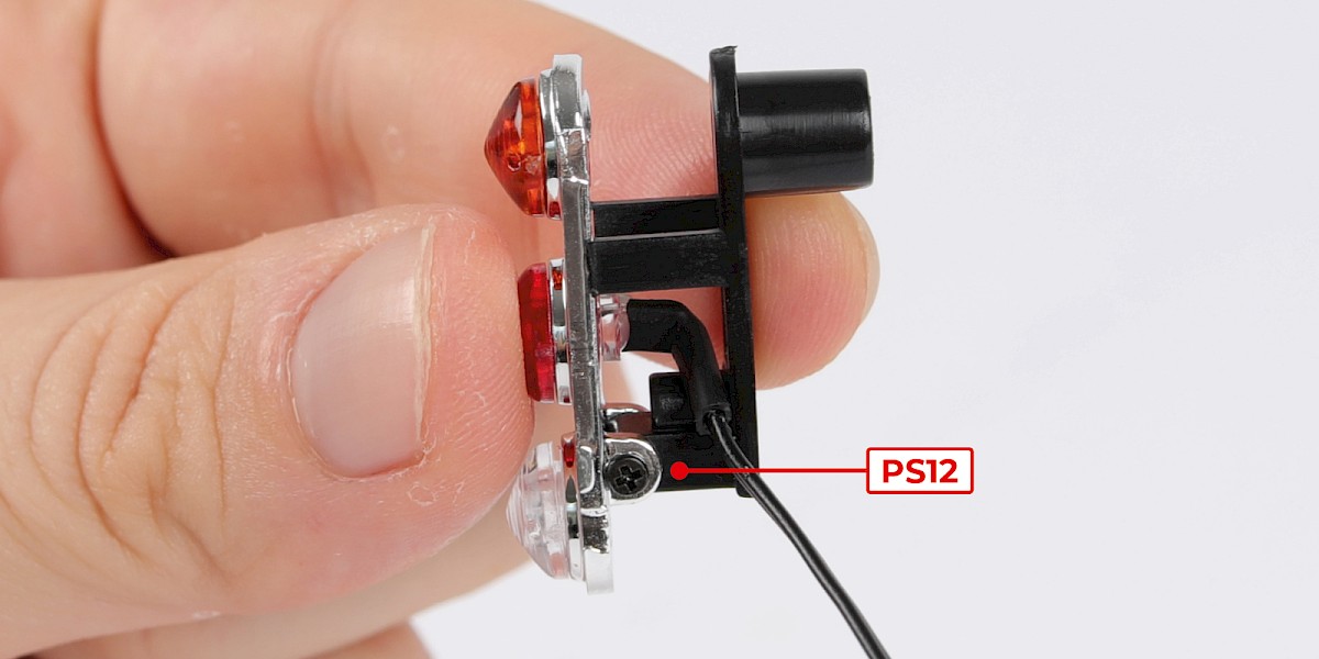
Secure the oil slick jet mount on the other side with 1x PS12.
Do not overtighten the screws, the part should be able to move freely as shown.

Step 7
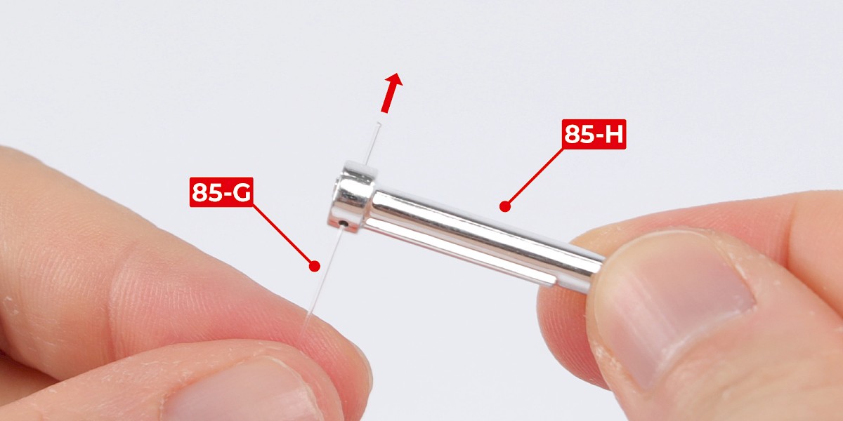
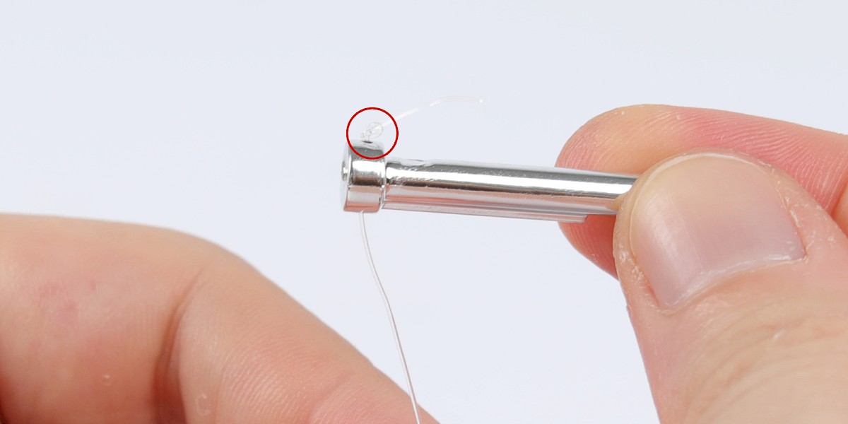
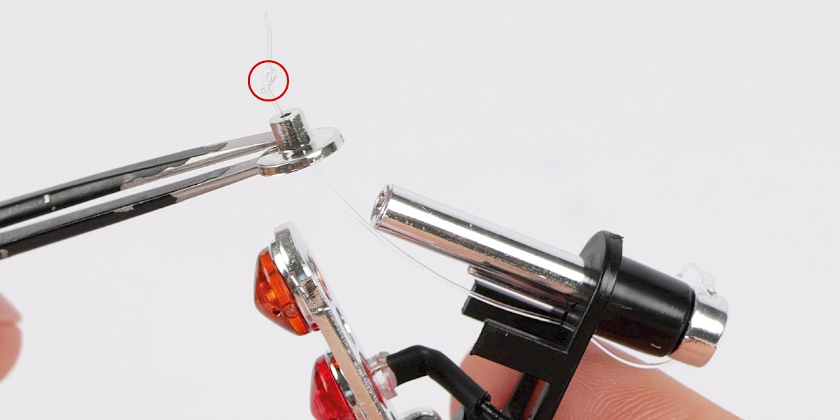
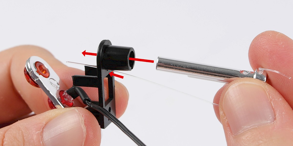
Thread the nylon string (85-G) through the oil slick jet (85-H). Make sure the parts are in the orientation shown.
Tie a knot in the end of the nylon string.
Step 8
Insert the nylon string and the oil slick jet into the assembly as shown.


Step 9
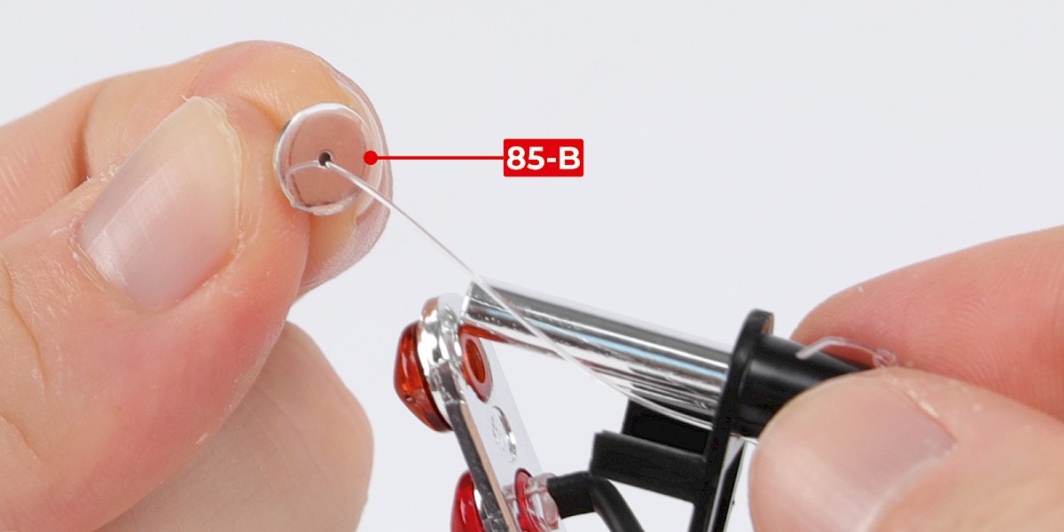
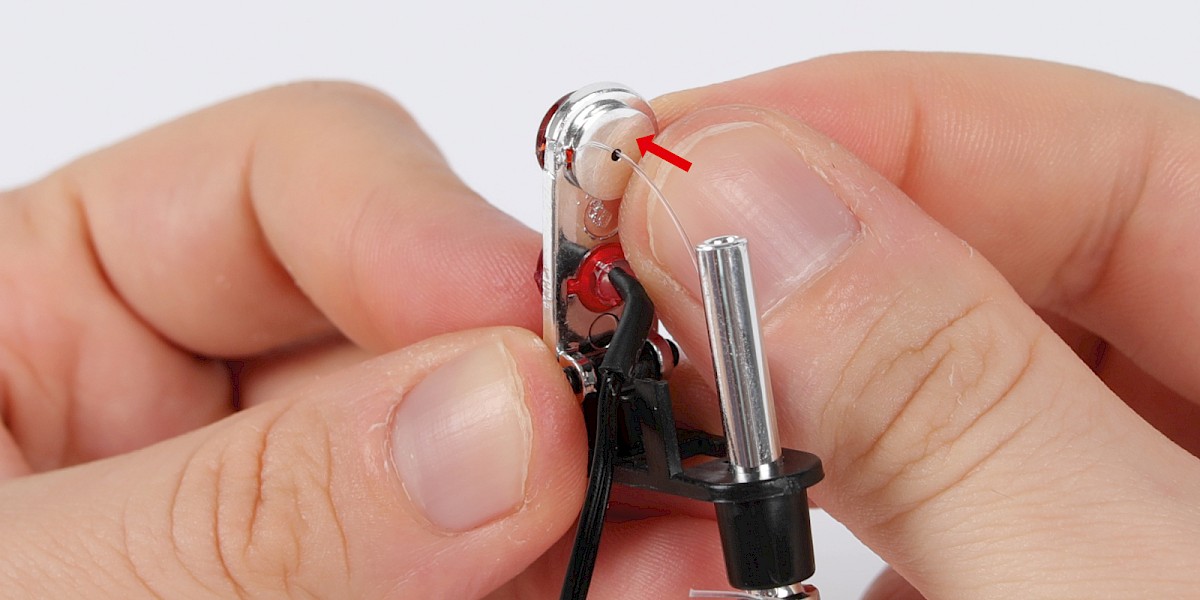
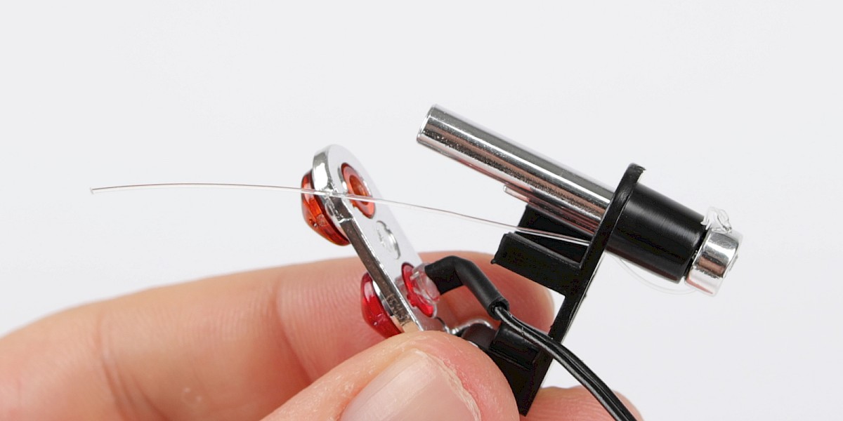
Thread the nylon string into the cap (85-B).
Tie a knot in the end of the nylon string.
Step 10
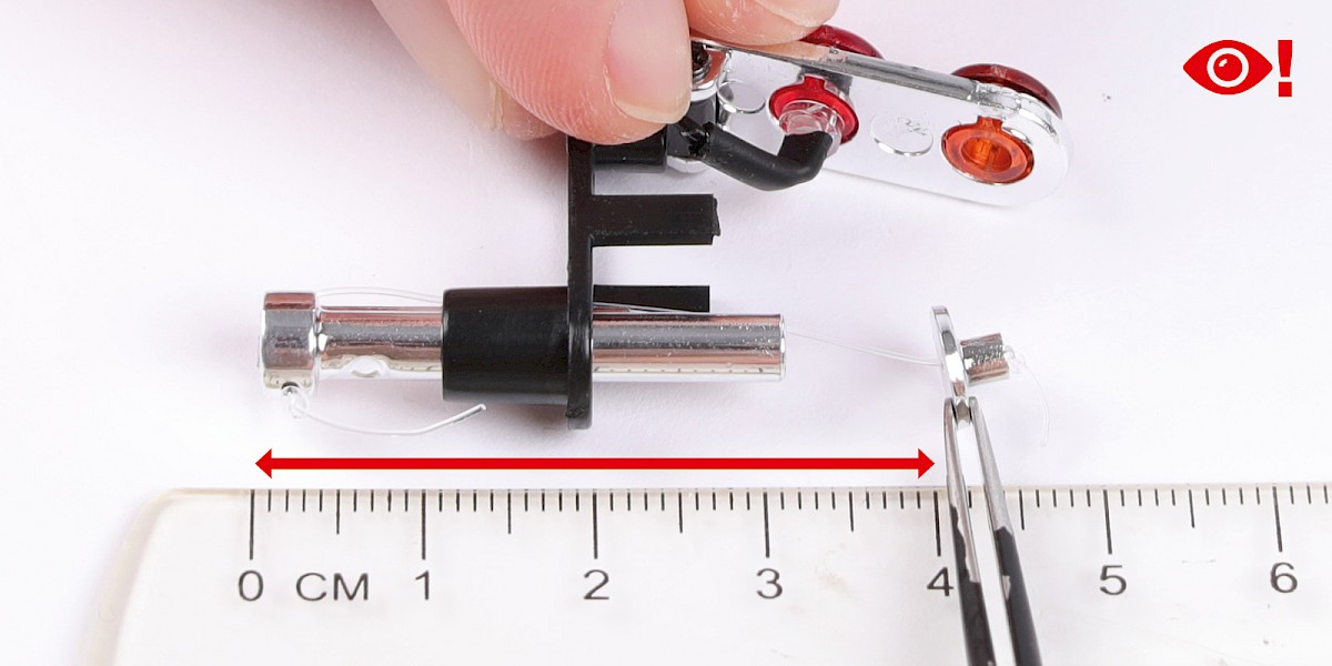
Check that the nylon string is the correct length.
Gently pull the cap until the nylon string is tight and measure the distance between the rear of the oil slick jet and the cap. The distance should be approximately 4cm. Adjust the knots in the nylon string if necessary.

Step 11
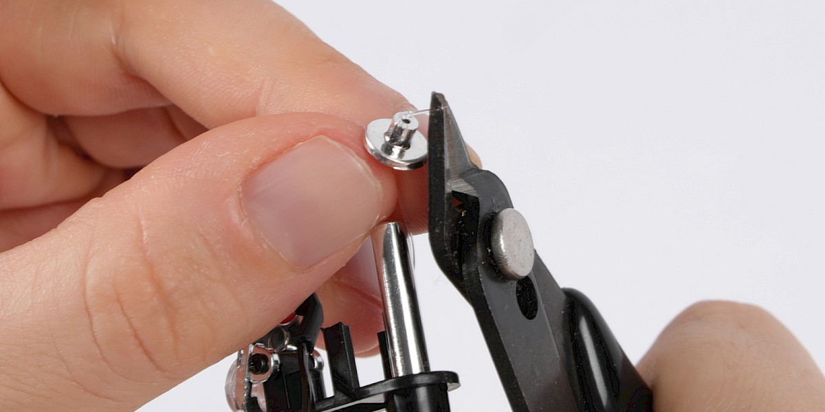
Trim the nylon string if necessary, then press the cap into the indicator light lens.
Step 12
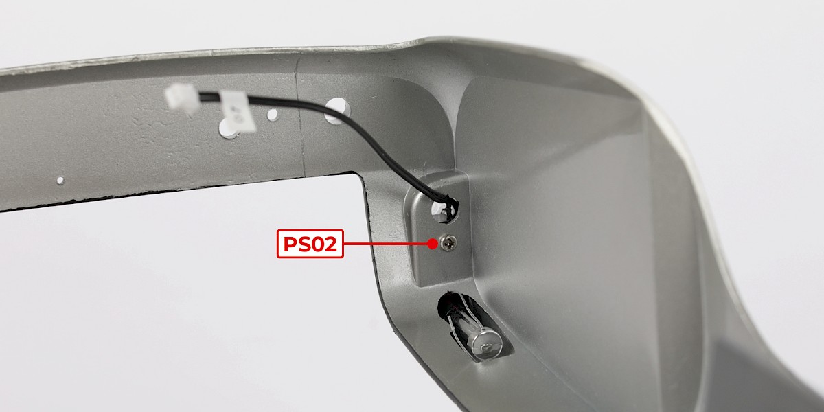
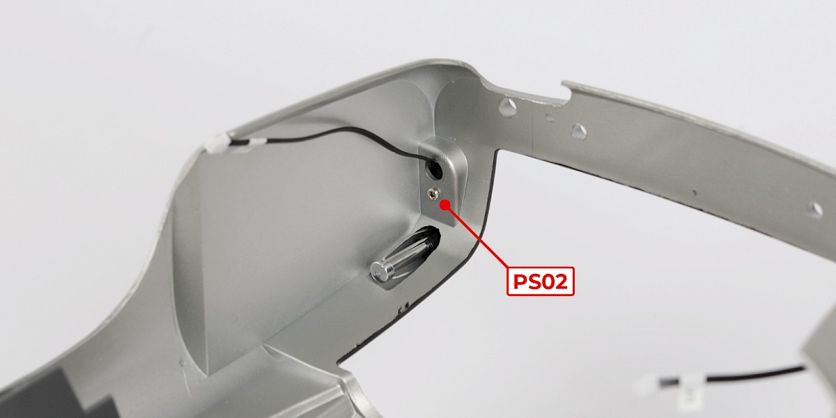
Fit the assembly into the main body.
Secure with 1x PS02.
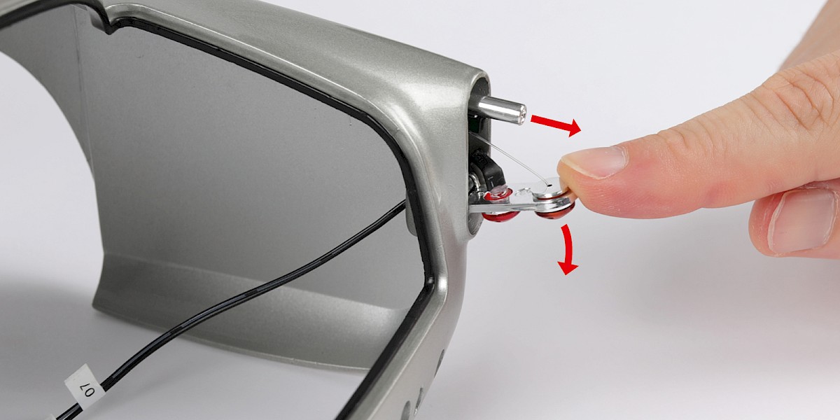
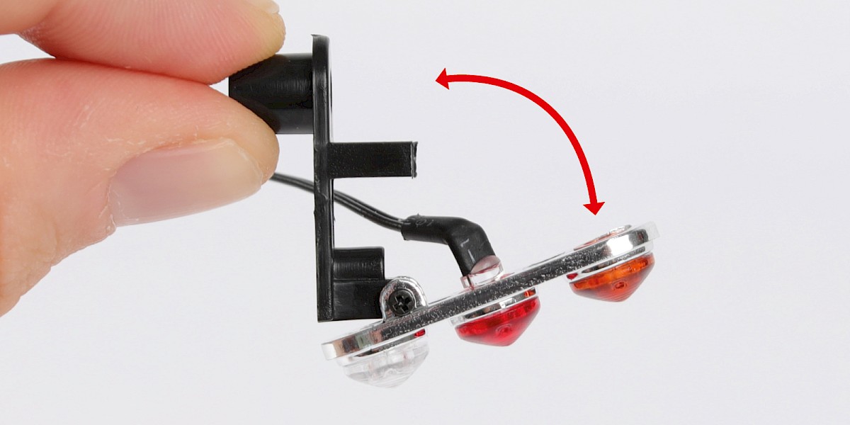
Step 13
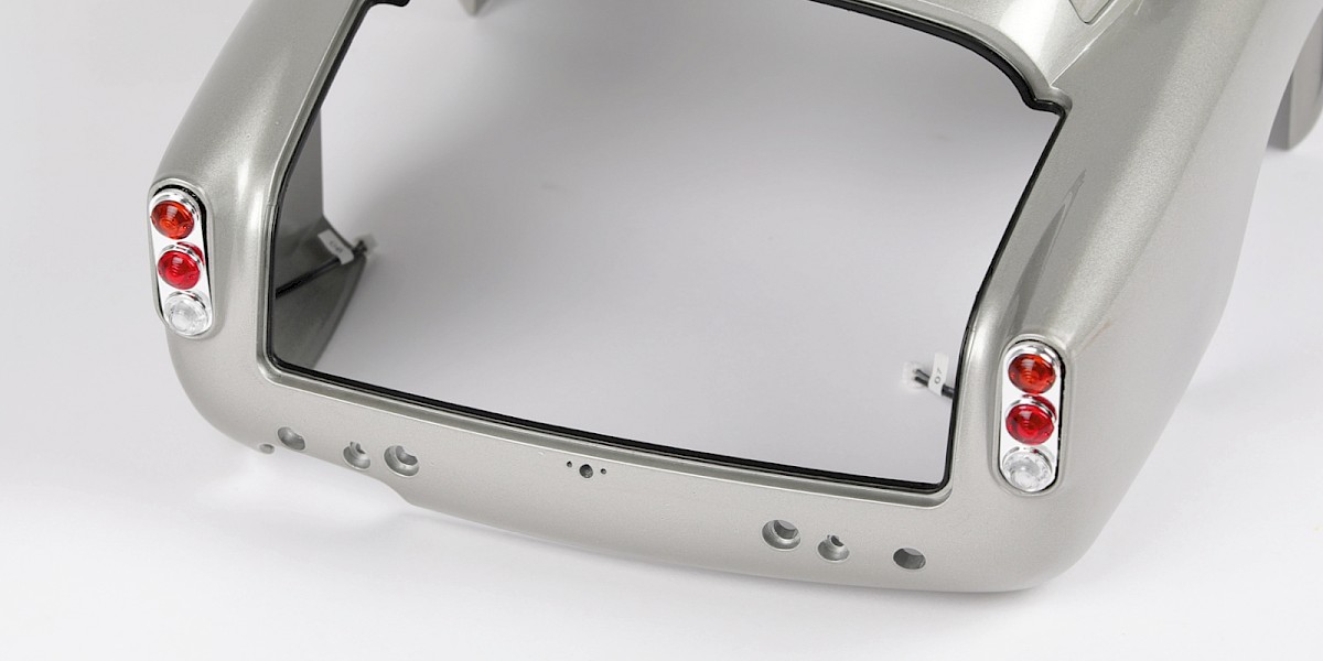
The rear right lights have been fitted. Pulling the rear lights downwards deploys the oil slick jet.
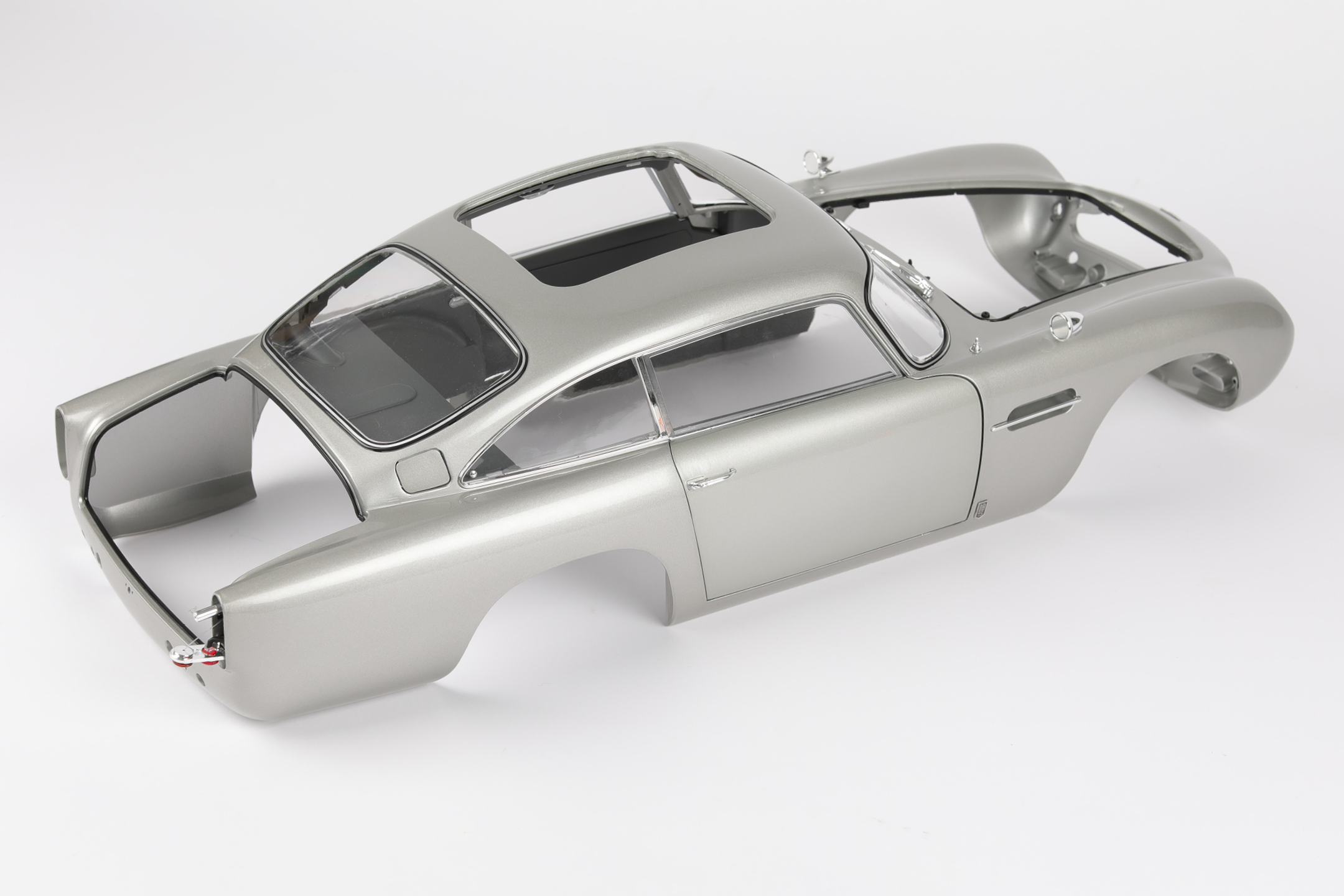
STAGE COMPLETE
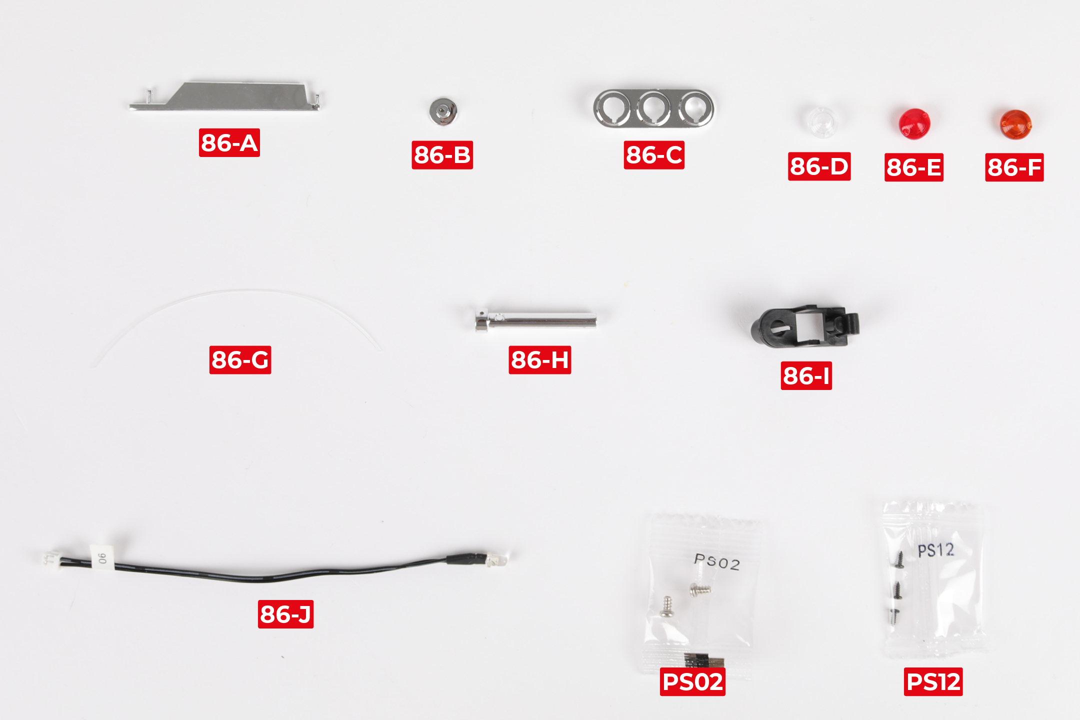
PARTS LIST
| 86-A Side strake | 86-G Nylon string |
| 86-B Cap | 86-H Oil slick jet |
| 86-C Rear light housing | 86-I Oil slick jet mount |
| 86-D Reverse light lens | 86-J Brake light LED |
| 86-E Brake light lens | 2x PS02 screws |
| 86-F Indicator light lens | 3x PS12 screws |
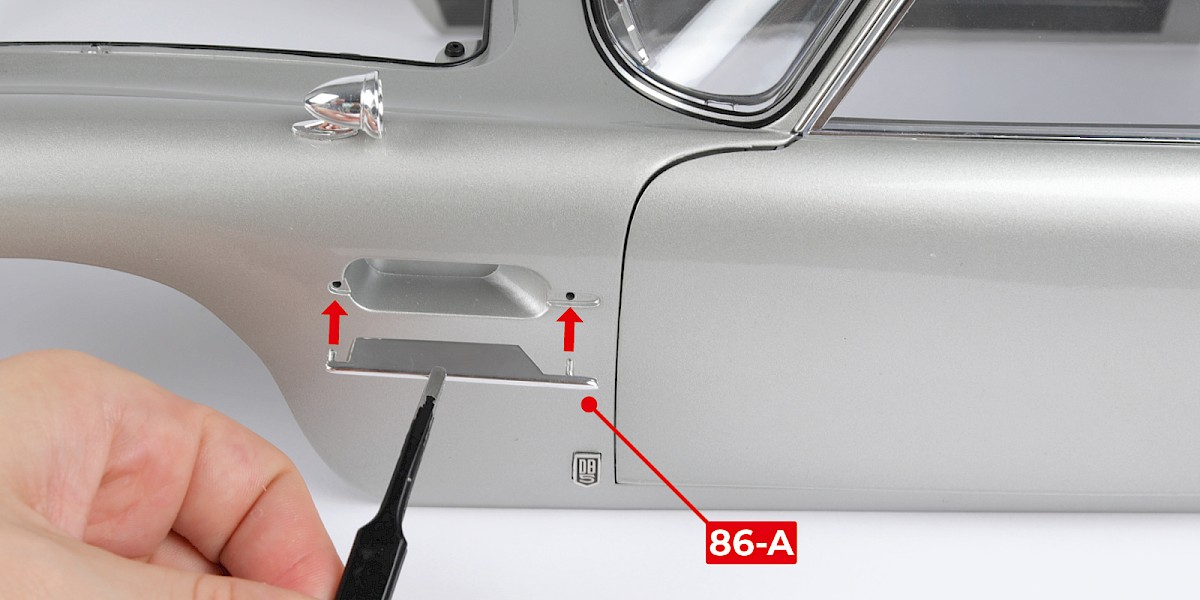
Step 1
Fit the side strake (86-A) on the left side of the main body (stage 85).
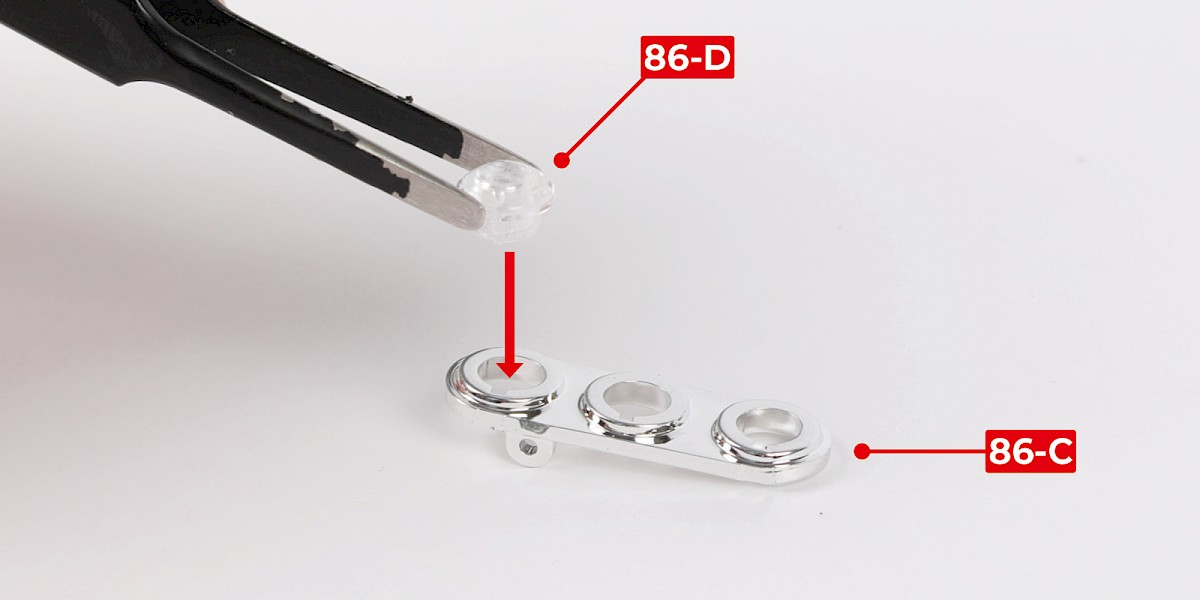
Step 2
Fit the reverse light lens (86-D) into the rear light housing (86-C).
Step 3
Fit the brake light lens (86-E) and the indicator light lens (86-F) in place.

Step 4
Fit the brake light LED (86-J) into the brake light lens.
Bend the cable to the side.


Step 5
Fit the oil slick jet mount (85-I) to the assembly.
Secure with 1x PS12.
Step 6
Secure the oil slick jet mount on the other side with 1x PS12.
Do not overtighten the screws, the part should be able to move freely as shown.

Step 7
Thread the nylon string (86-G) through the oil slick jet (86-H). Make sure the parts are in the orientation shown.
Tie a knot in the end of the string.


Step 8
Insert the nylon string and the oil slick jet into the assembly as shown.
Step 9
Thread the nylon string into the cap (86-B).
Tie a knot in the end of the nylon string.


Step 10
Check the nylon string is the correct length.
Gently pull the cap until the nylon string is tight and measure the distance between the rear of the oil slick jet and the cap. The distance should be approximately 4cm. Adjust the knots in the nylon string if necessary.
Step 11
Trim the nylon string if necessary, then press the cap into the indicator light lens.


Step 12
Fit the assembly into the main body.
Secure with 1x PS02.
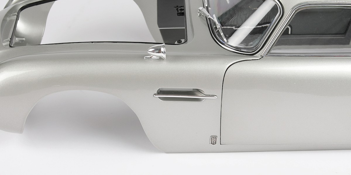
Step 13
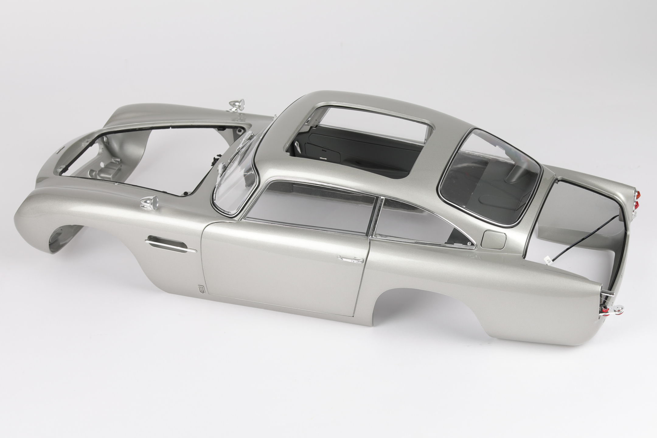
The rear lights have been fitted.
STAGE COMPLETE
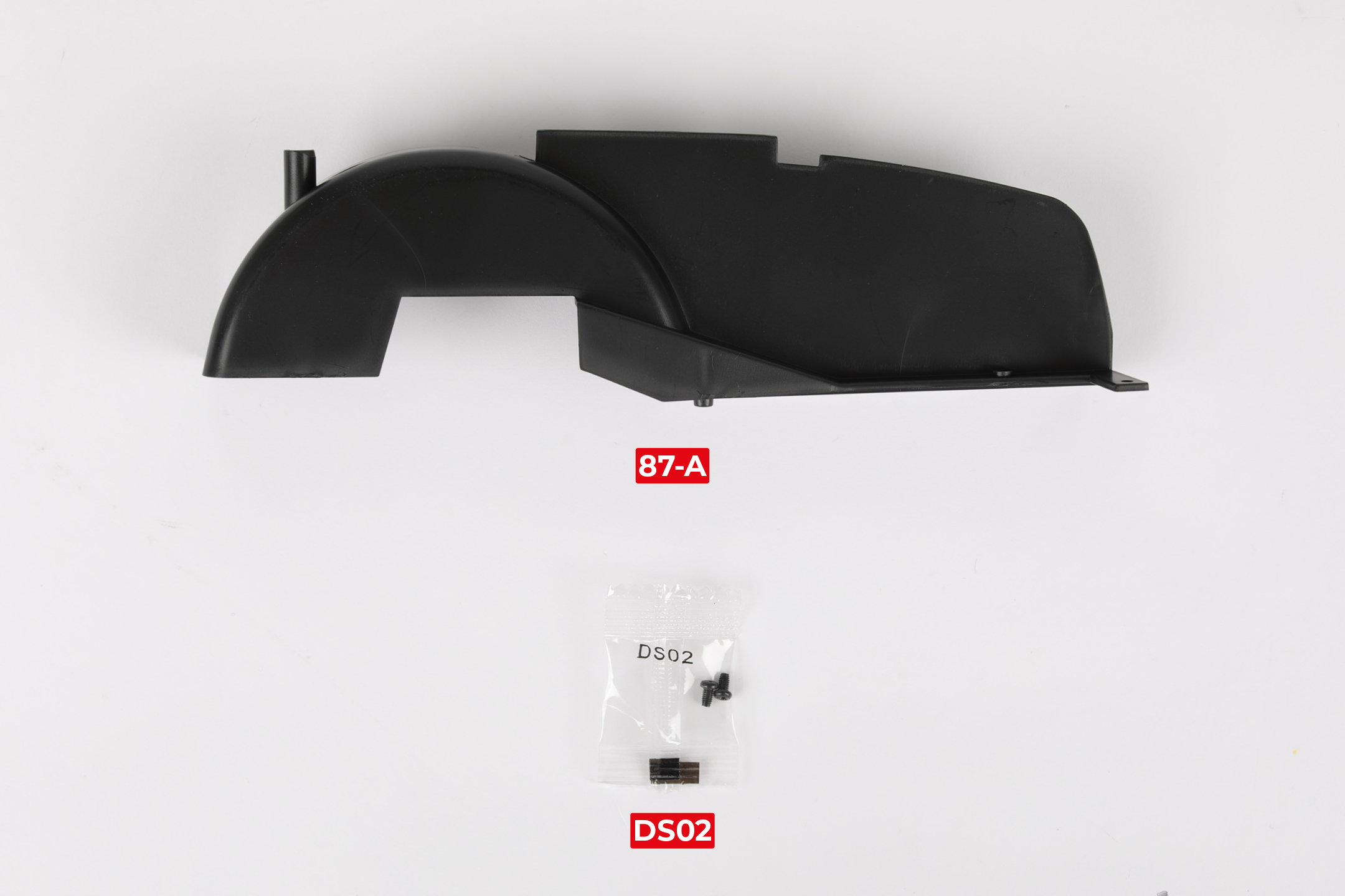
PARTS LIST
| 87-A Rear right wheel arch liner |
| 2x DS02 screws |

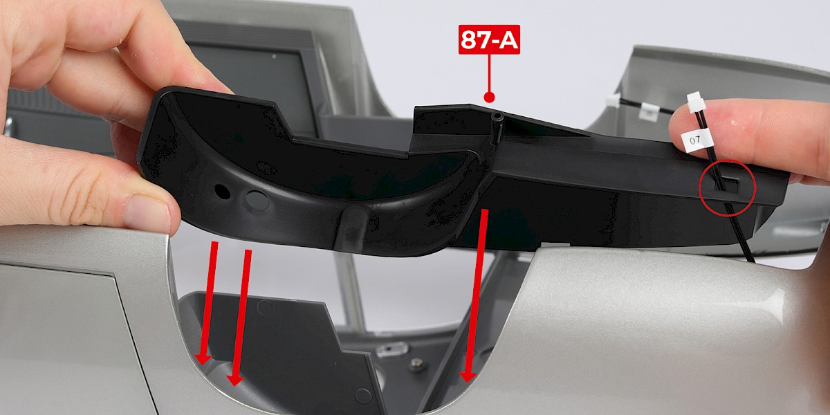
Step 1
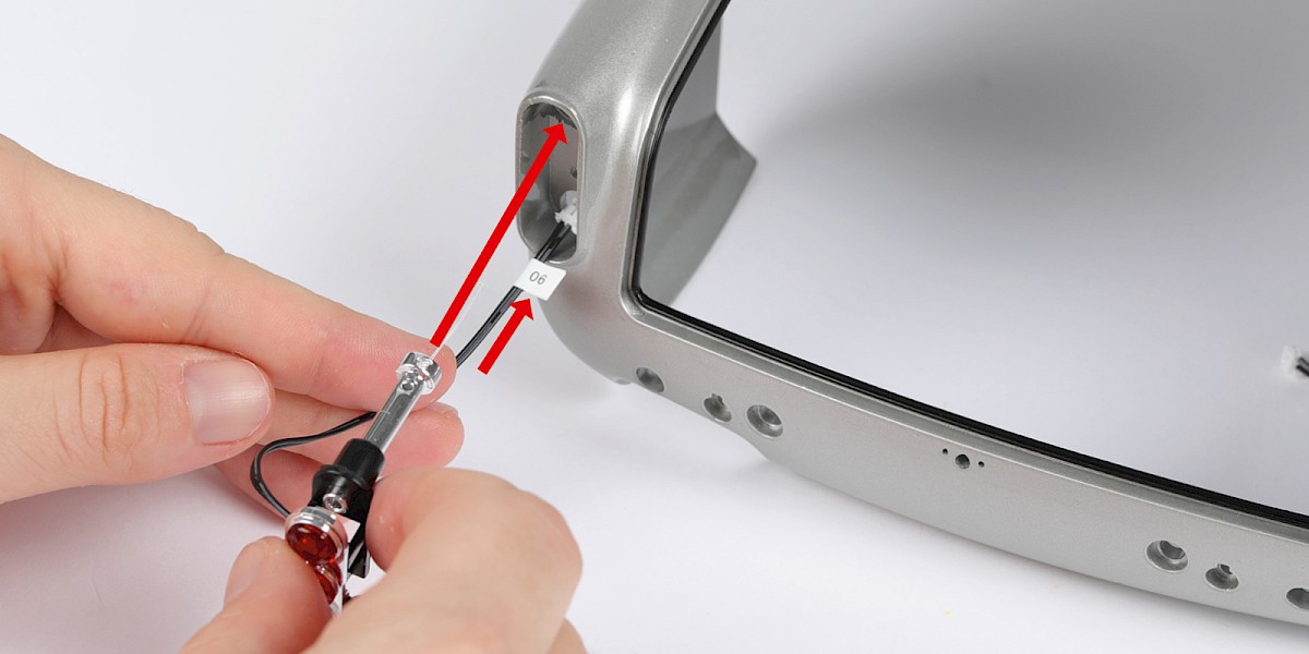
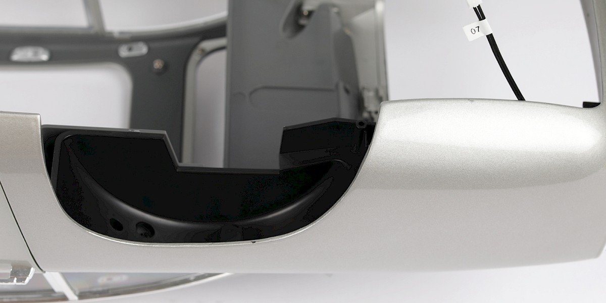
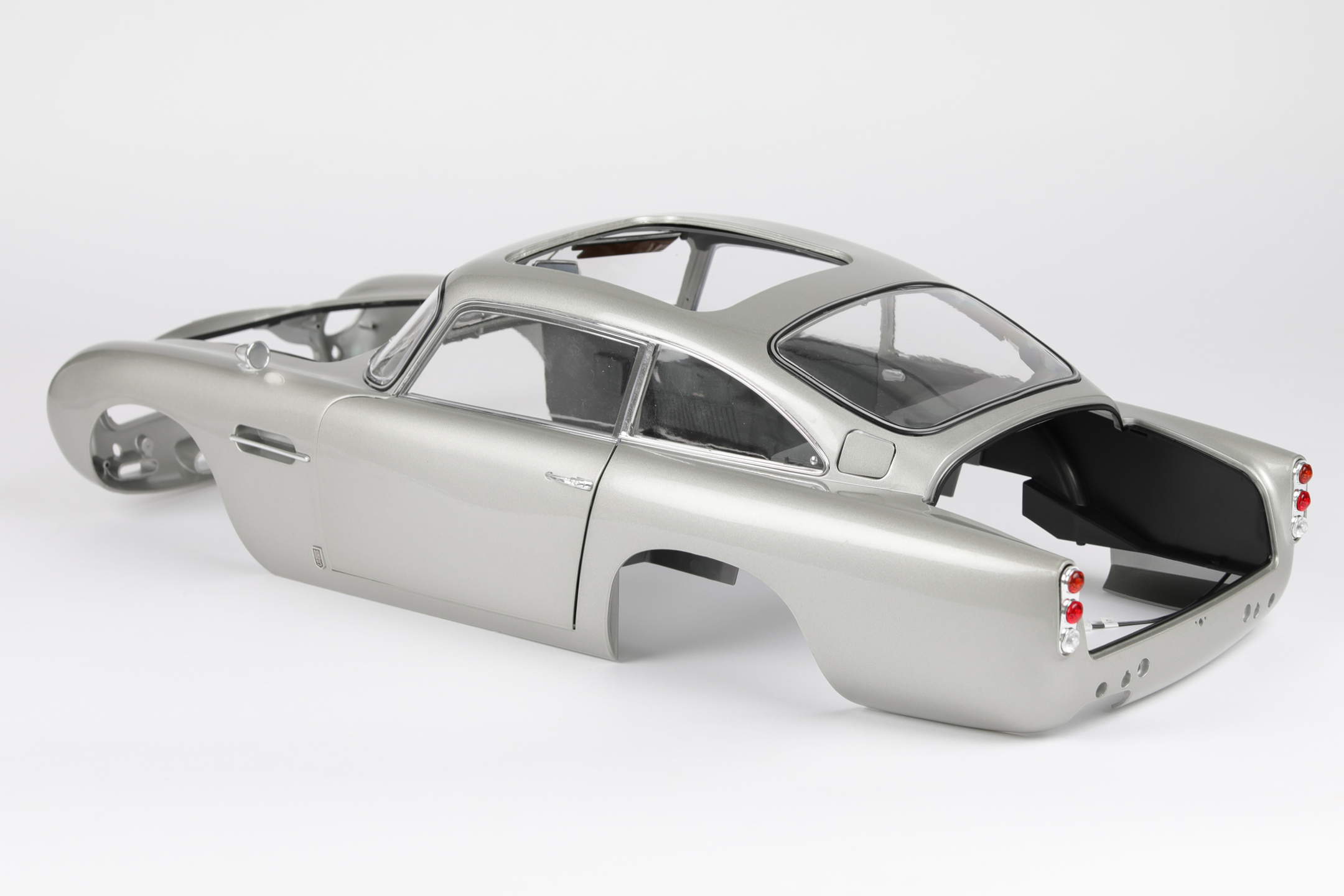
Fit the rear right wheel arch liner (87-A) to the main body (stage 86). Thread the brake light LED through the hole (circled).
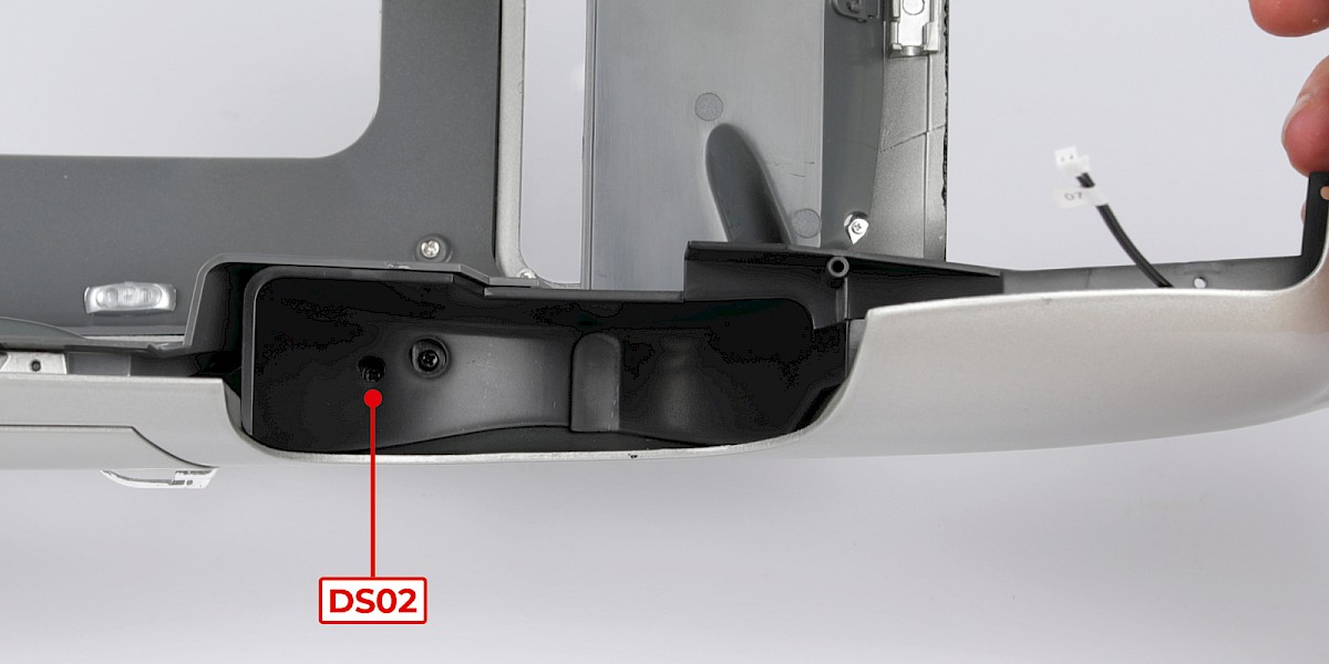
Step 2
Secure with 1x DS02.
STAGE COMPLETE
PARTS LIST
| 88-A Rear left wheel arch liner |
| 2x DS02 screws |
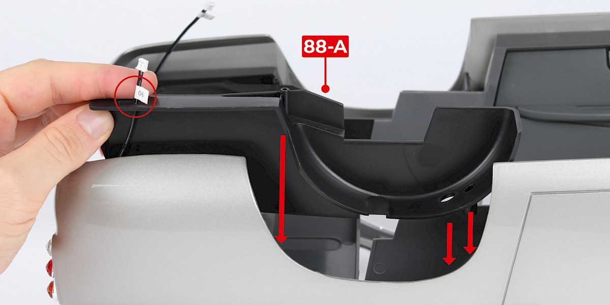
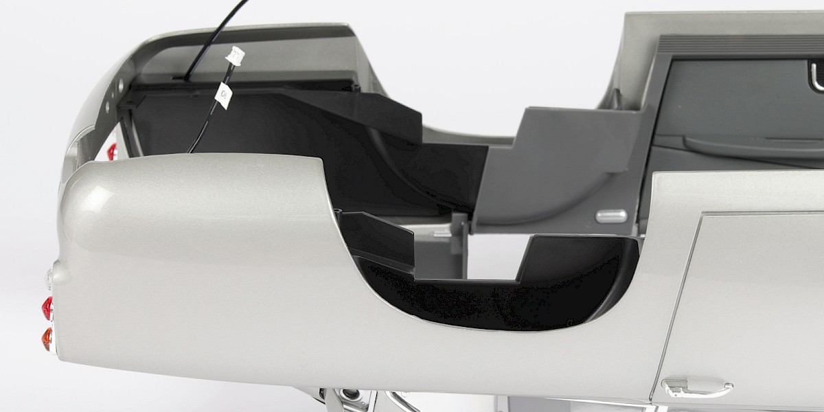
Step 1
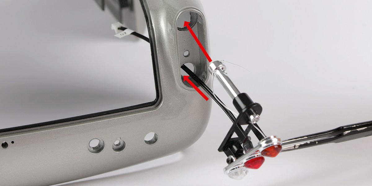
Pass the brake light LED cable through the rectangular hole in the left rear wheel arch (88-A).
Set the left rear wheel arch (88-A) as shown in the image.
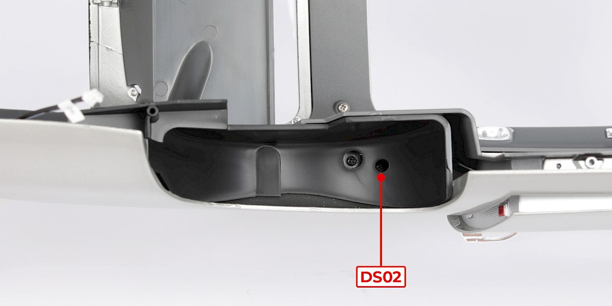
Step 2
Secure with 1x DS02.
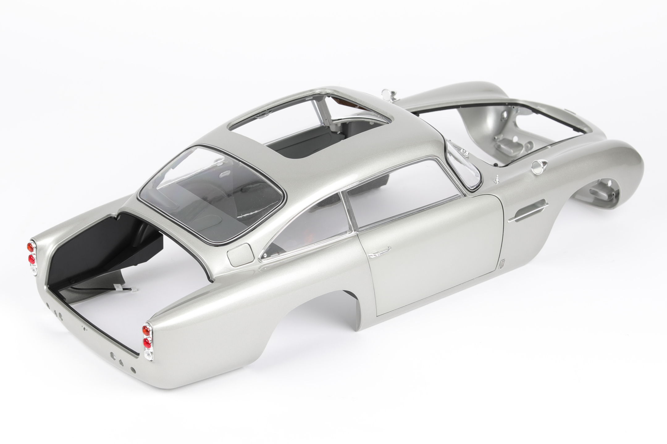
STAGE COMPLETE
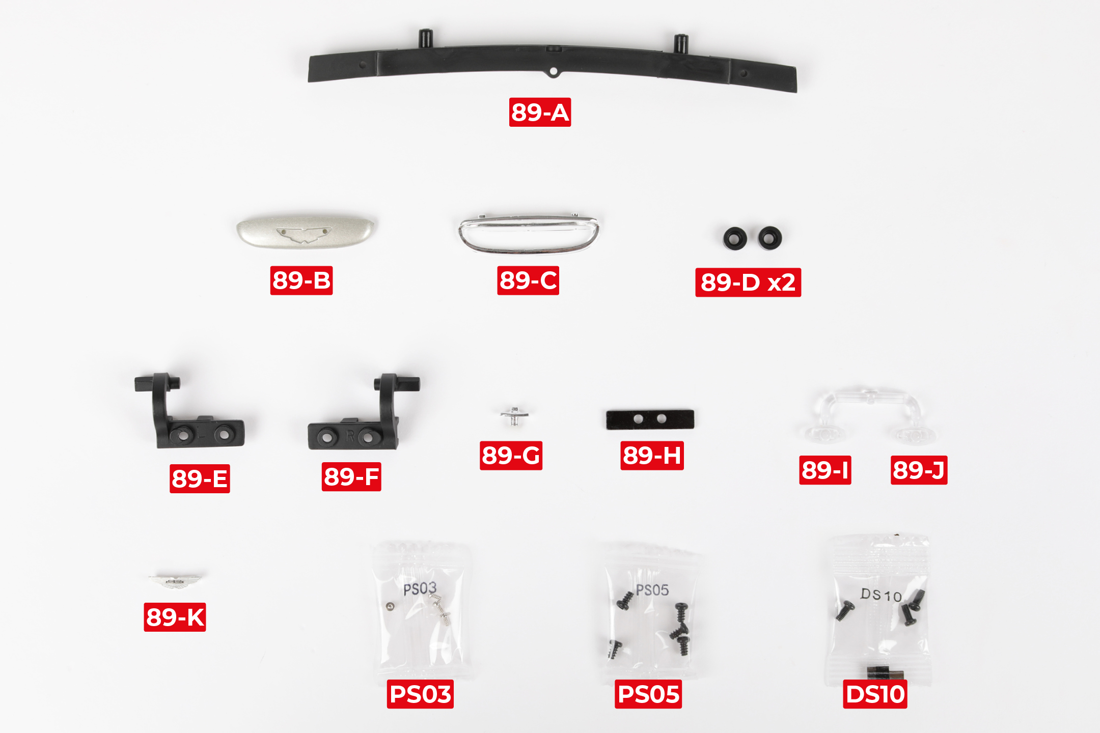
PARTS LIST
| 89-A Rear reinforcement frame | 89-H Hinge bracket |
| 89-B Boot handle | 89-I Number plate light (L) |
| 89-C Boot handle trim | 89-J Number plate light (R) |
| 89-D Buffer | 89-K Aston Martin badge |
| 89-E Boot hinge (L) | 4x PS03 screws |
| 89-F Boot hinge (R) | 5x PS05 screws |
| 89-G Boot lock | 3x DS10 screws |
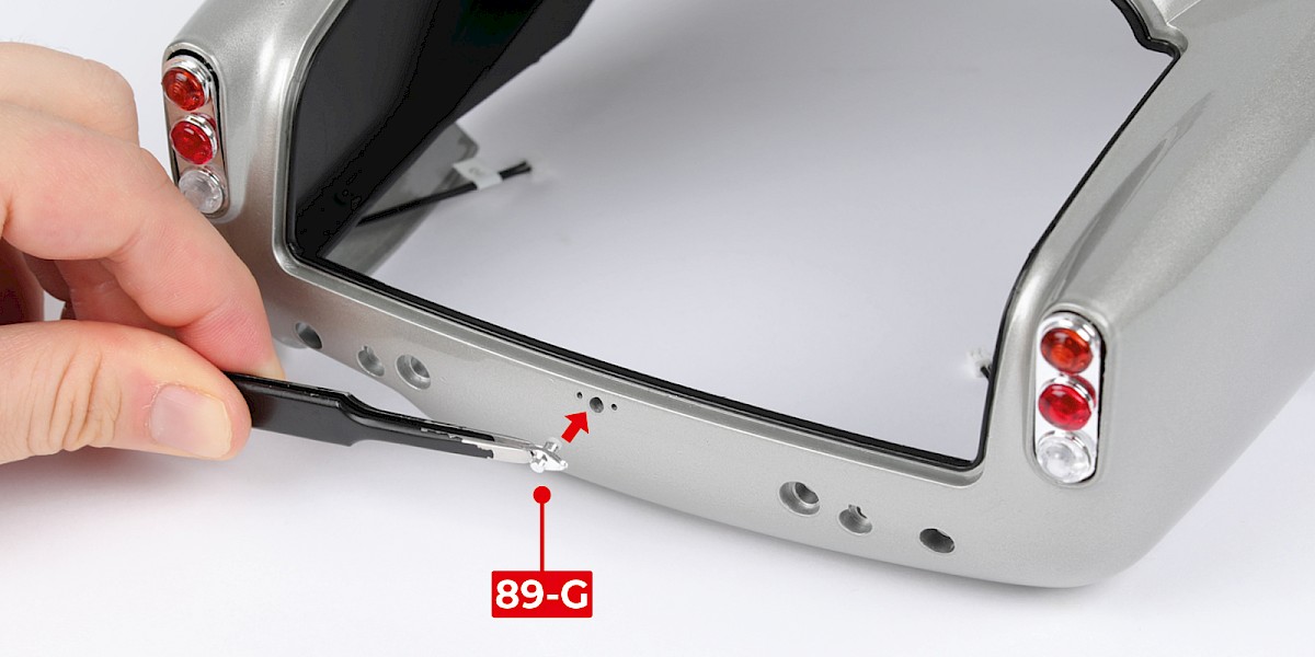
Step 1
Fit the boot lock (89-G) to the main body (stage 88).
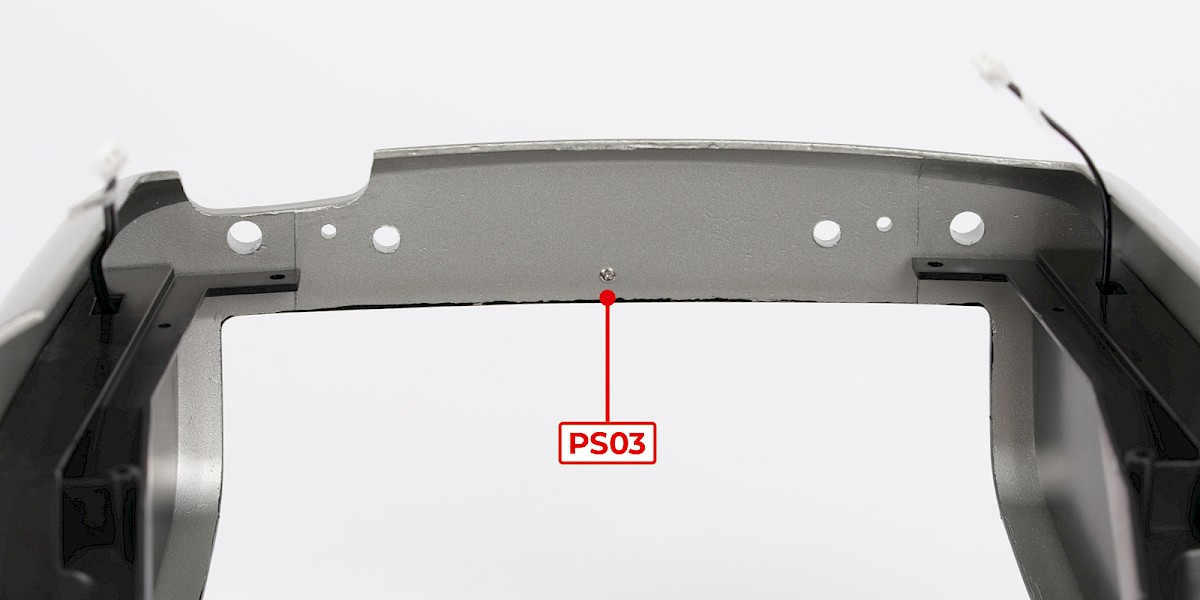
Step 2
Secure with 1x PS03.
Step 3
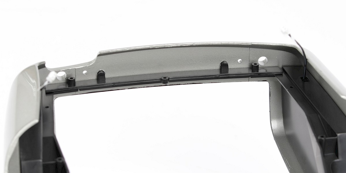
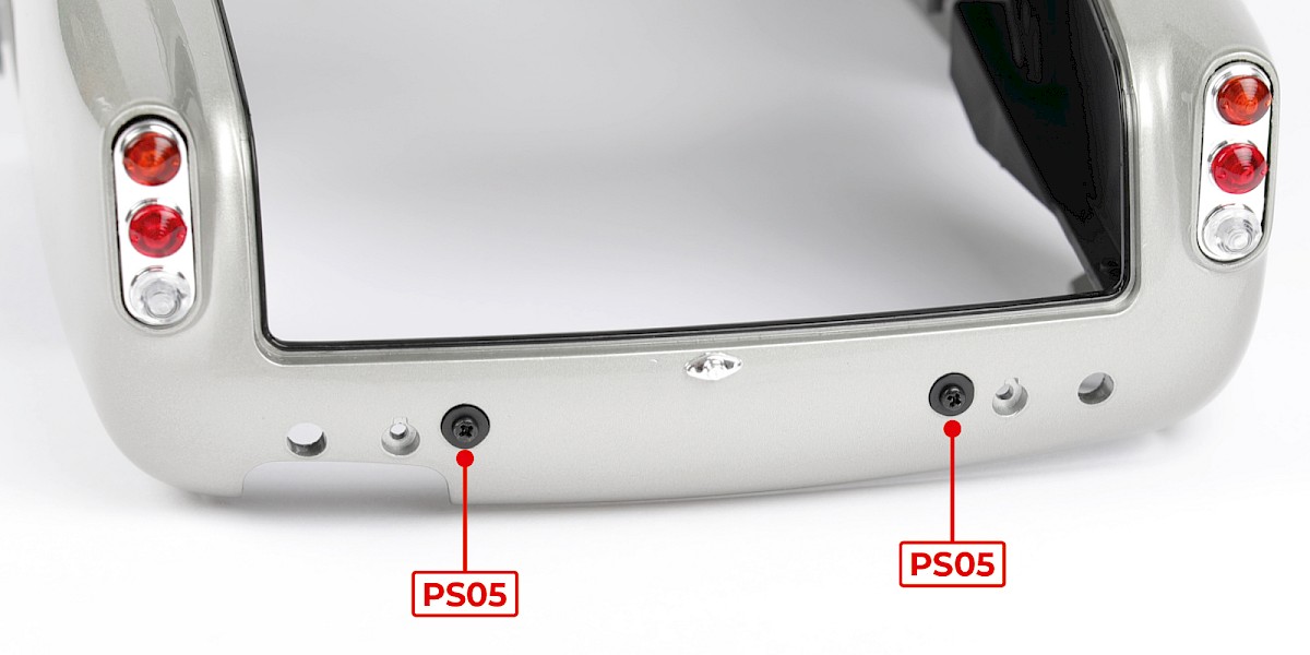
Fit the rear reinforcement frame (89-A) to the assembly.
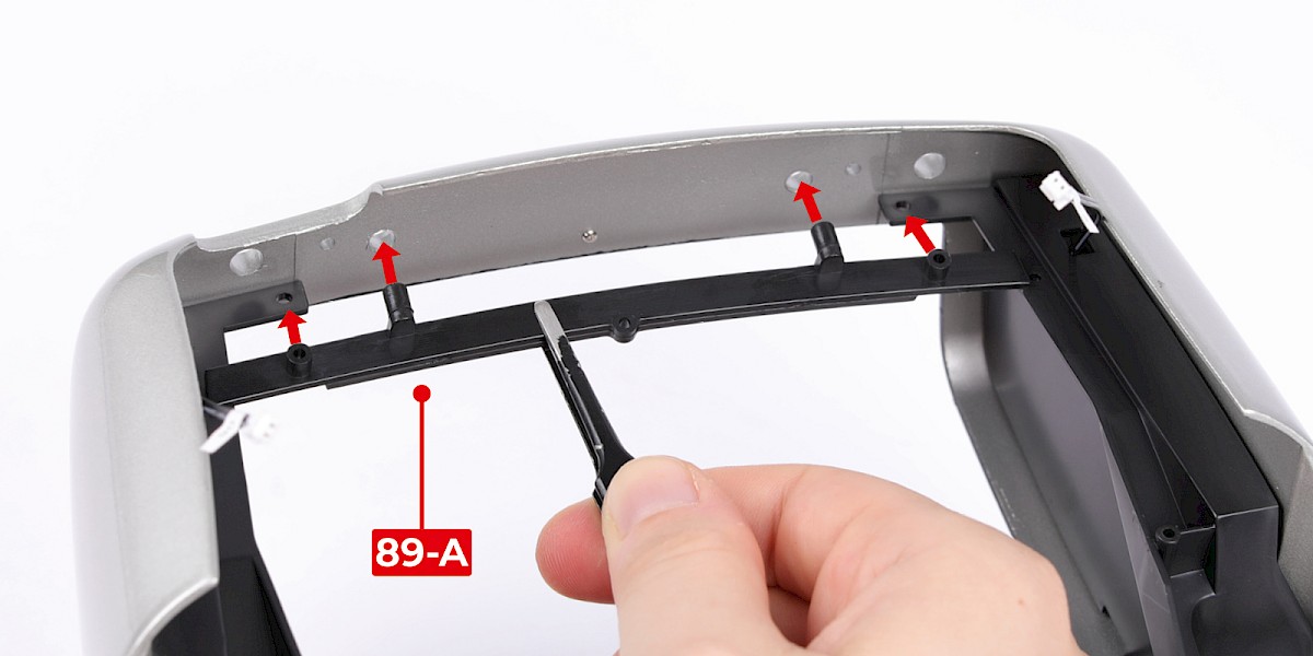
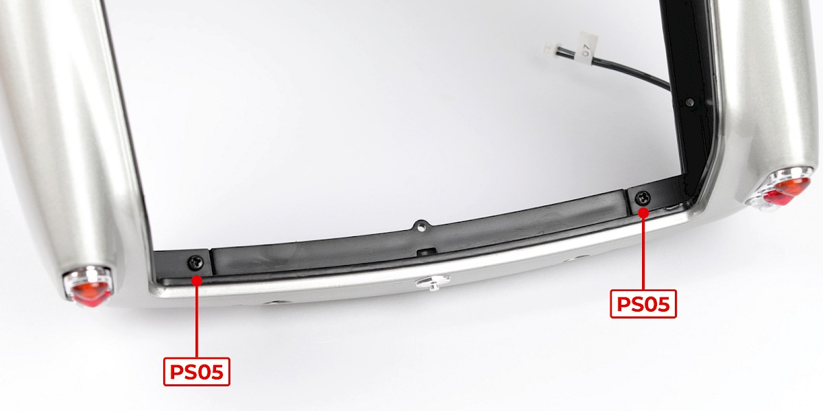
Step 4
Secure with 2x PS05.
Step 5
Fit a buffer (89-D) to the assembly.
Fit the second buffer as shown.
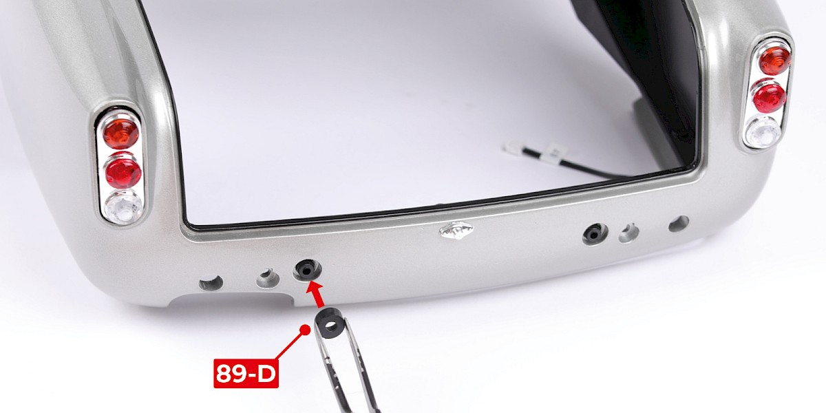
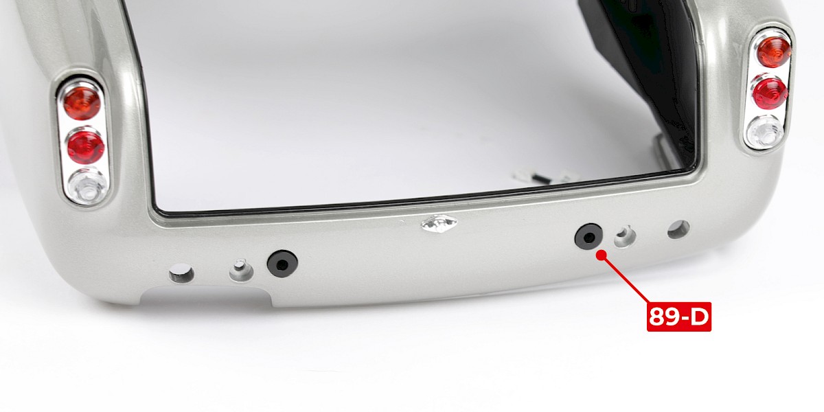
Step 6
Secure with 2x PS05.
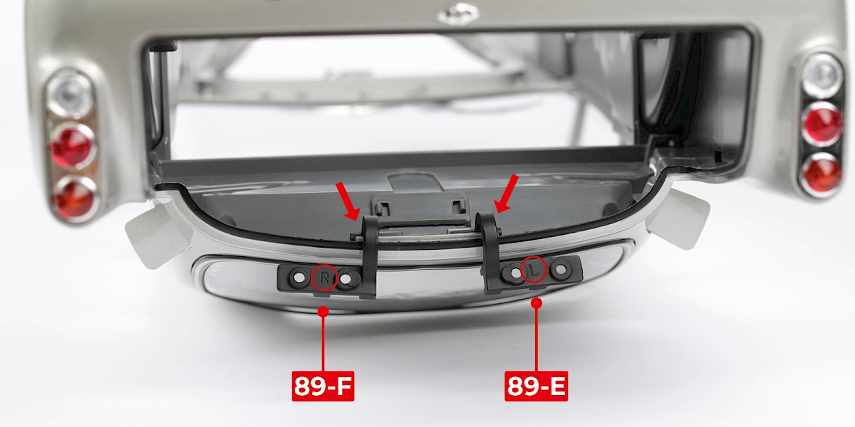
Step 7
Fit the right boot hinge (89-F) and the left boot hinge (89-E) to the assembly. The parts are marked with "R" and "L" (circled).
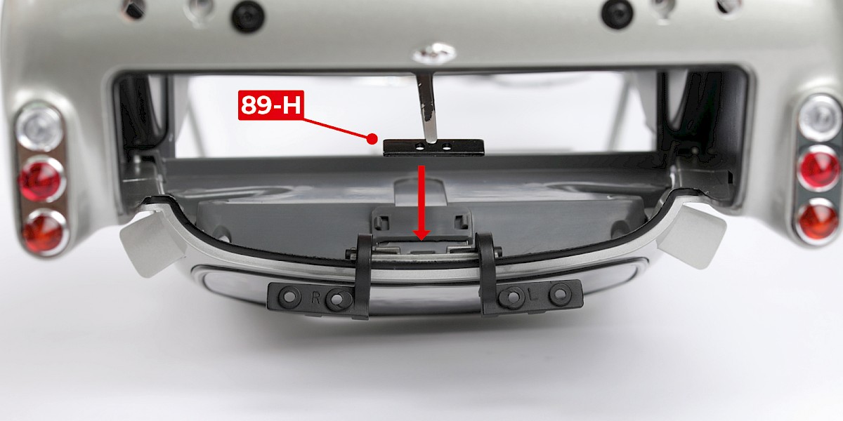
Step 8
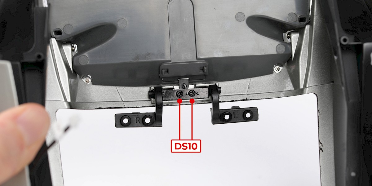
Fit the hinge bracket (89-H) to the assembly.
Secure with 2x DS10. Make sure the screws are tightened.
Step 9
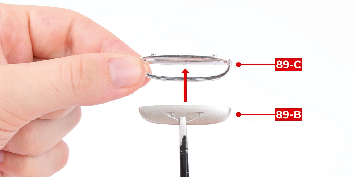
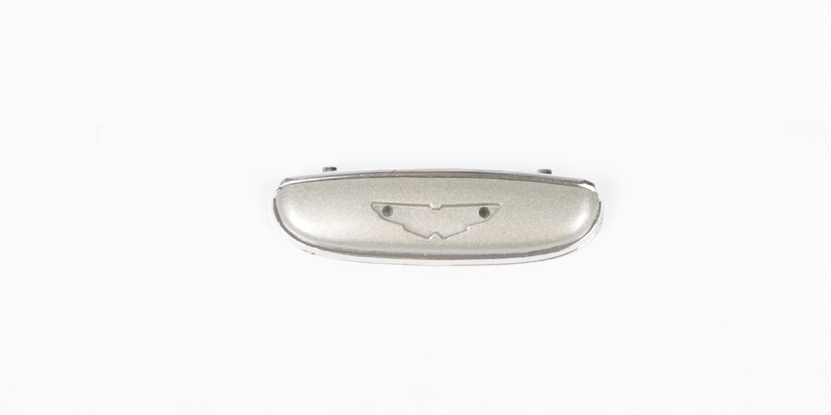
Fit the boot handle (89-B) to the boot handle trim (89-C).
Step 10
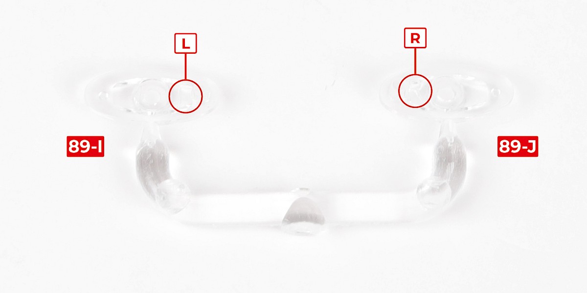
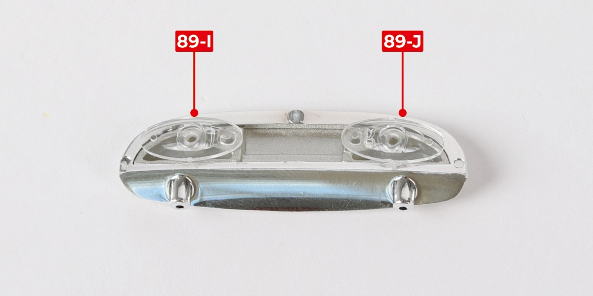
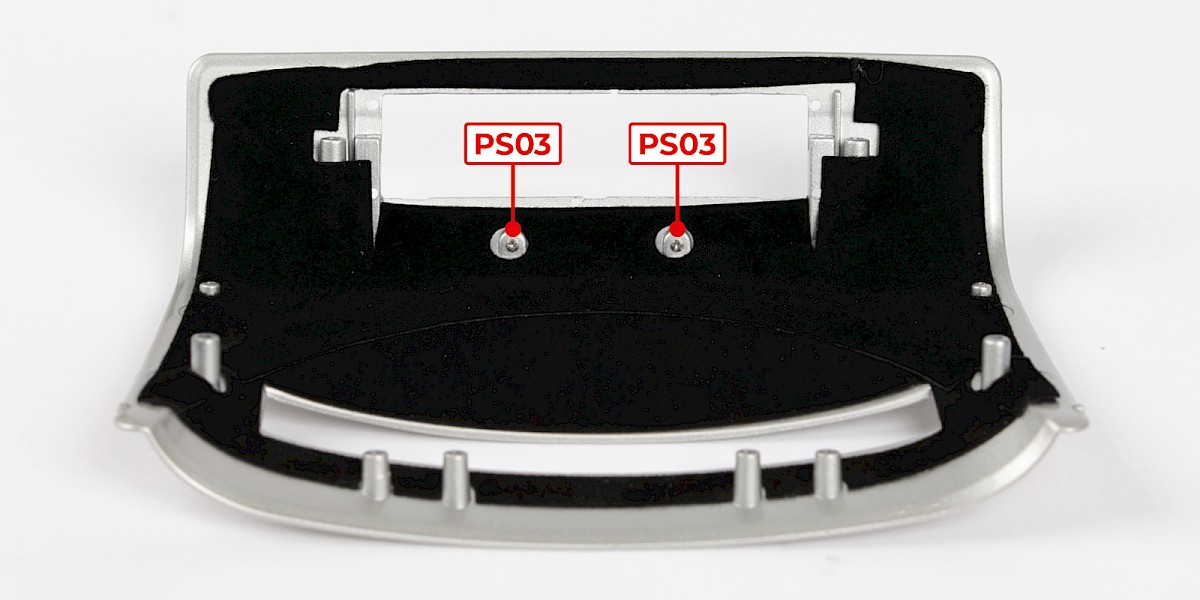
The number plate lights are marked with "L" and "R" as indicated. Cut the parts from the sprue.
Fit the left number plate light (89-I) and the right number plate light (89-J) to the assembly.
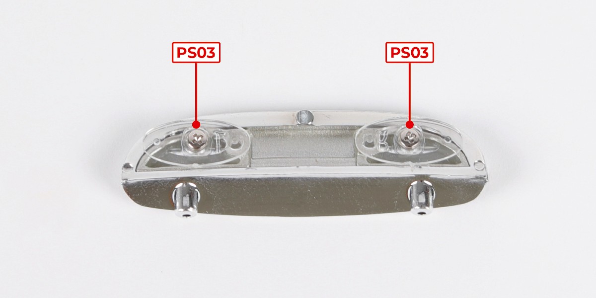
Step 11
Secure with 2x PS03.
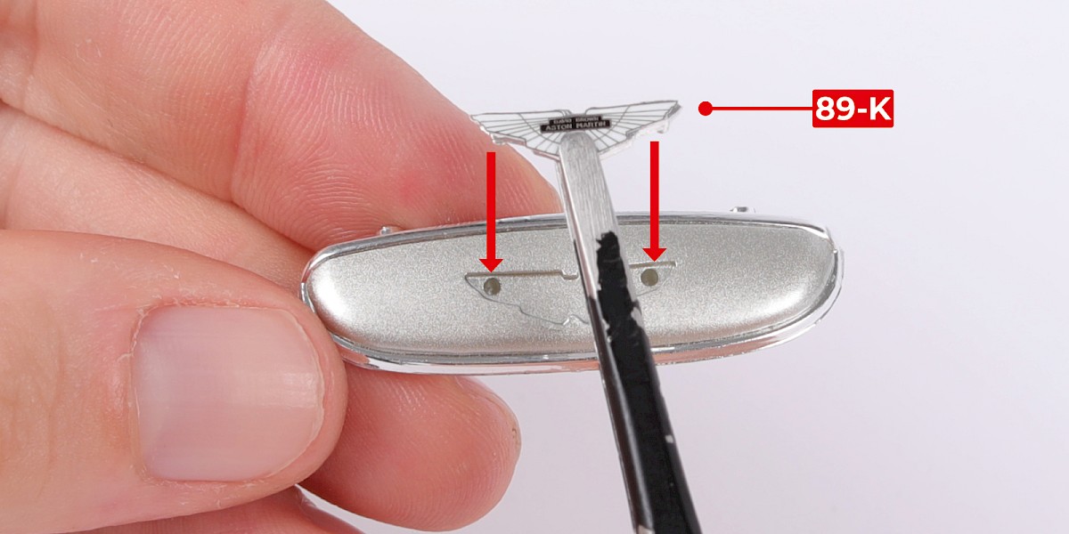
Step 12
Fit the Aston Martin badge (89-K) to the assembly.
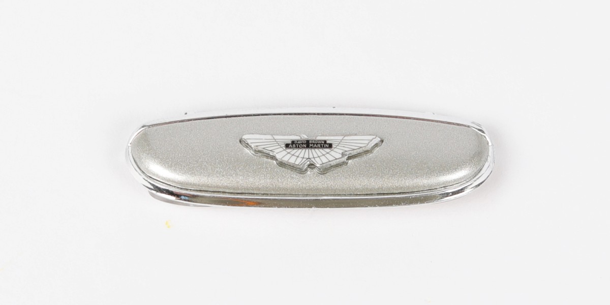
STAGE COMPLETE
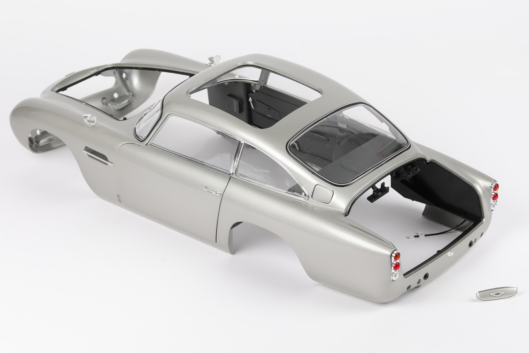
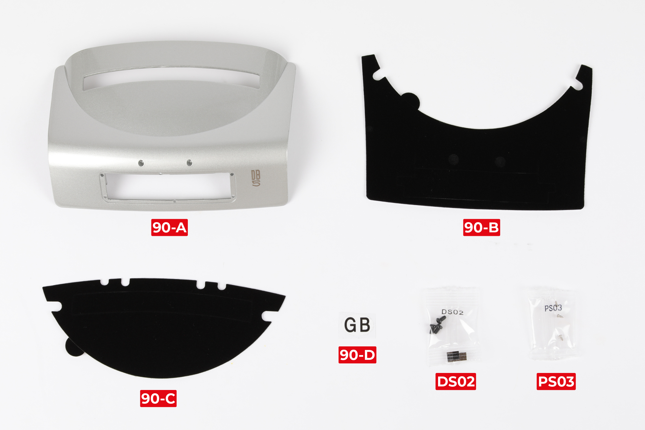
PARTS LIST
| 90-A Boot lid |
| 90-B Self-adhesive felt 1 |
| 90-C Self-adhesive felt 2 |
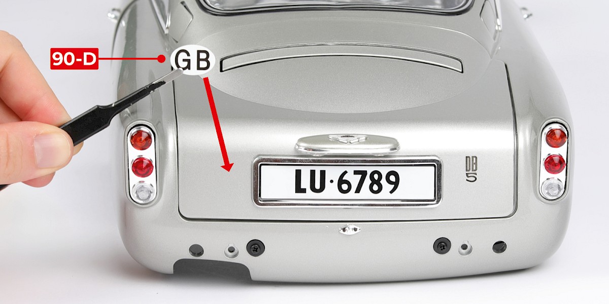
| 90-D GB sticker |
| 3x DS02 screws |
| 3x PS03 screws |
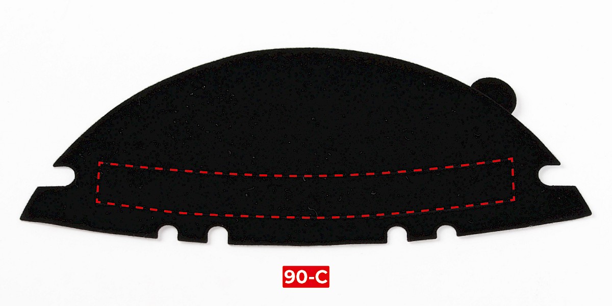
Step 1
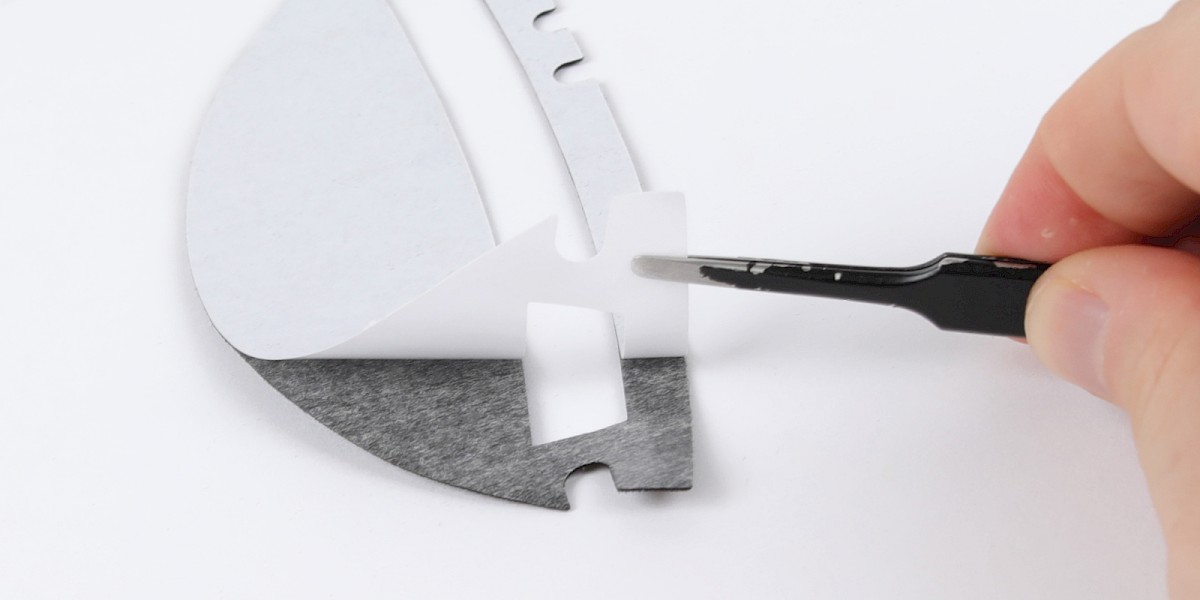
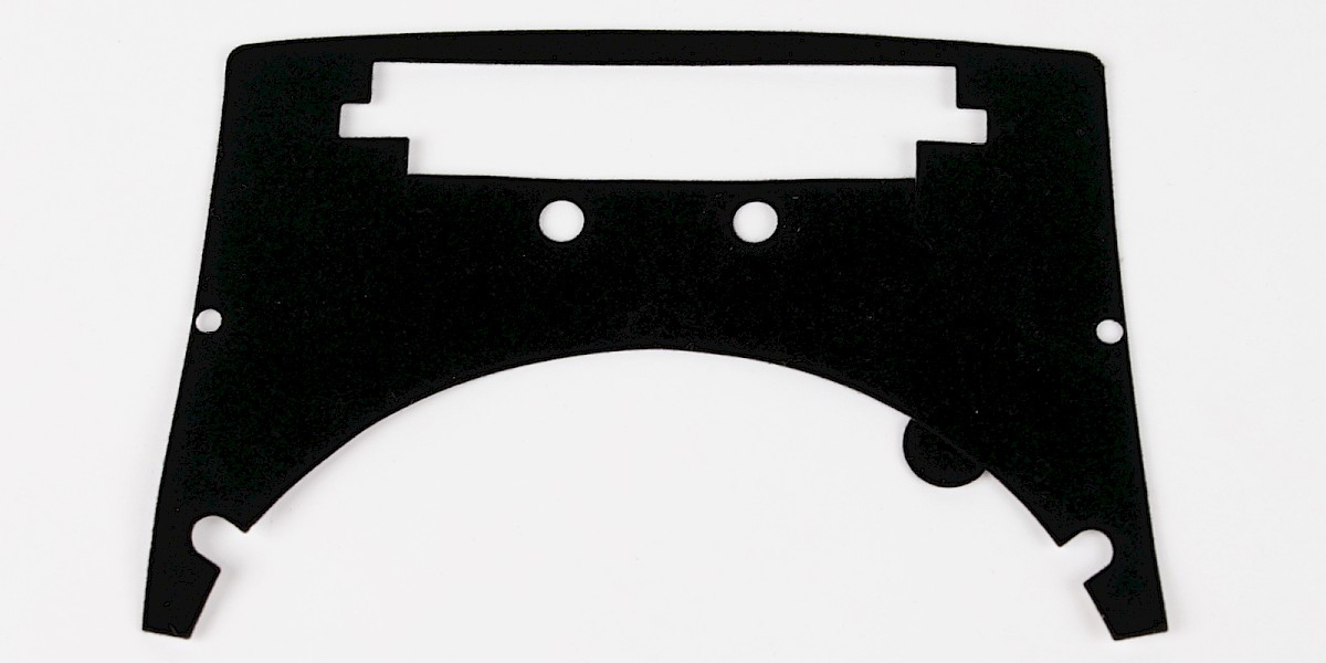
Remove the section highlighted in red from self-adhesive felt 2 (90-C).
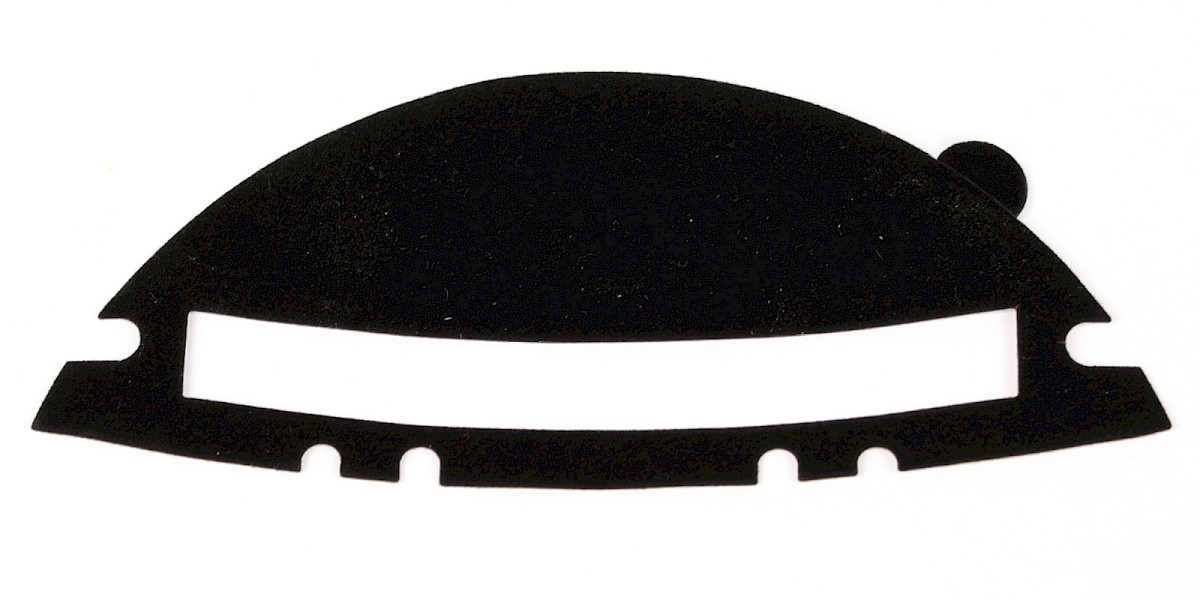
Step 2
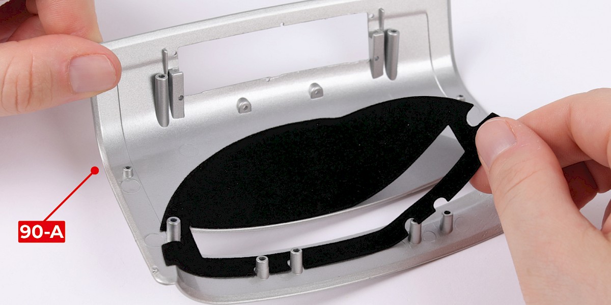
Peel the backing paper from self-adhesive felt 2.
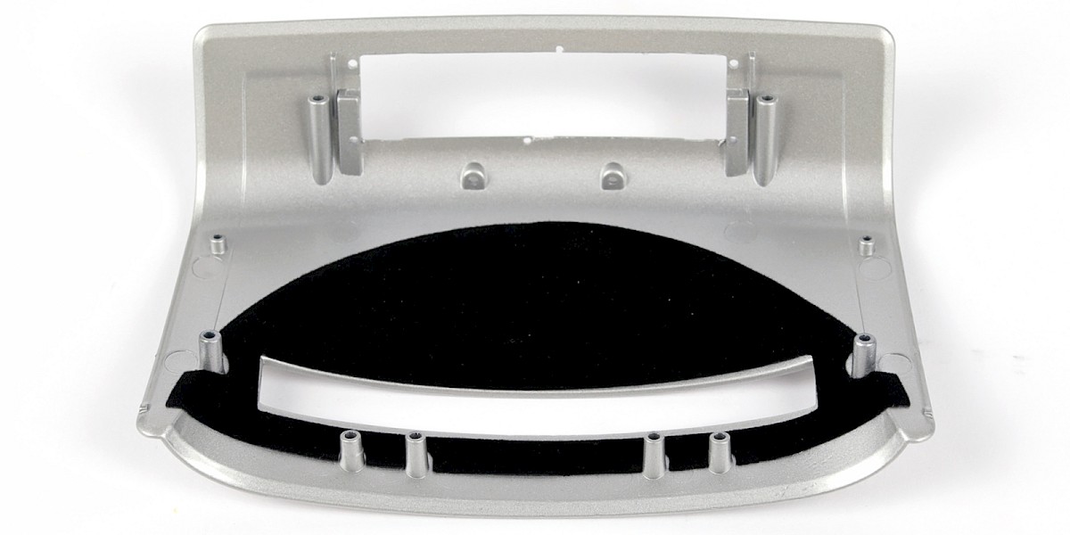
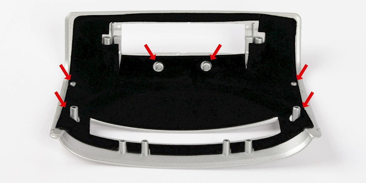
Step 3
Press the self-adhesive felt onto the boot lid (90-A). Fit around the screw posts as shown.
Step 4
Remove the section highlighted in red from self-adhesive felt 1 (90-B).
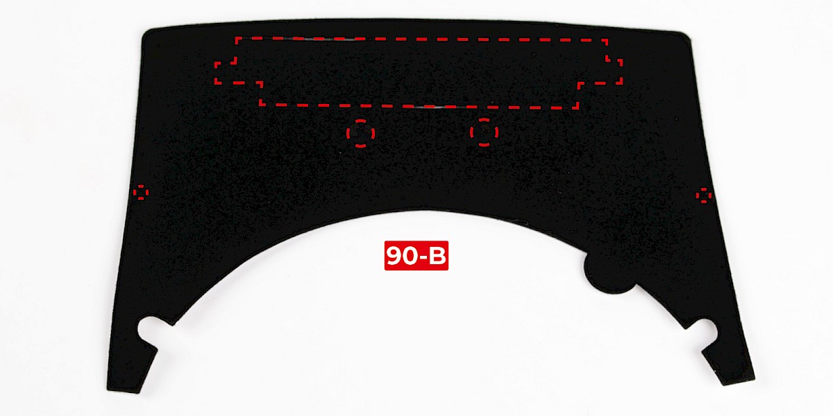
Step 5
Press the self-adhesive felt onto the assembly. Fit the gaps around the screw posts.
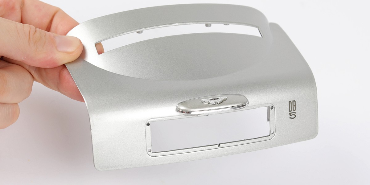
Step 6
Fit the boot handle (stage 89) to the boot lid.
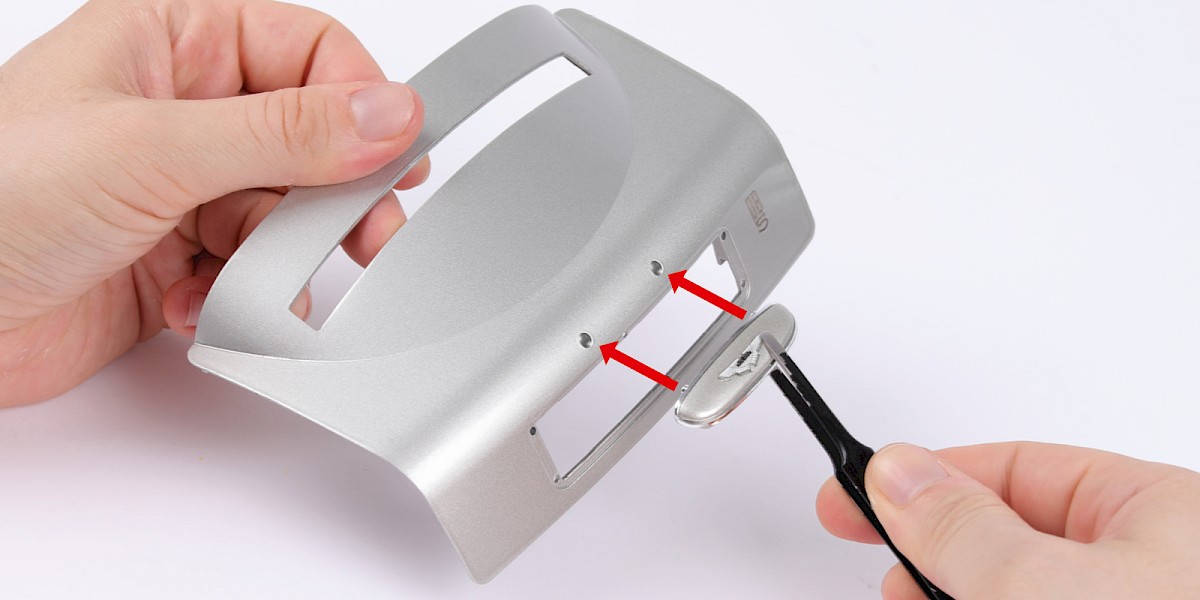
Step 7
Secure with 2x PS03.
Step 8
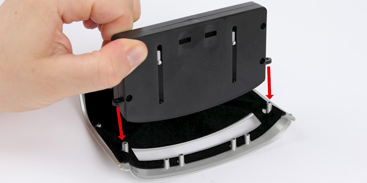
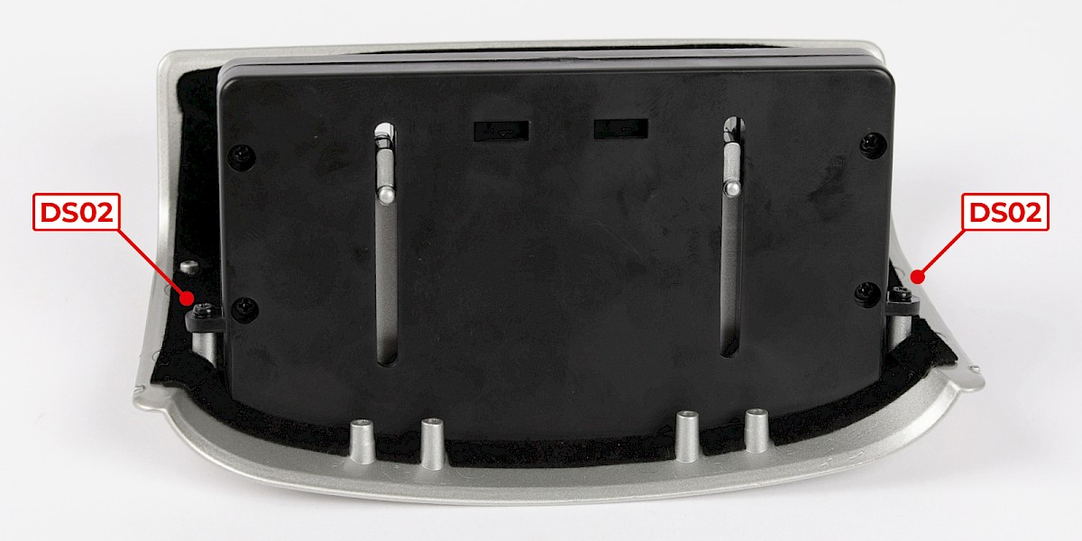
Fit the bulletproof screen (stage 65) to the assembly.
Secure with 2x DS02.
STAGE COMPLETE
PARTS LIST
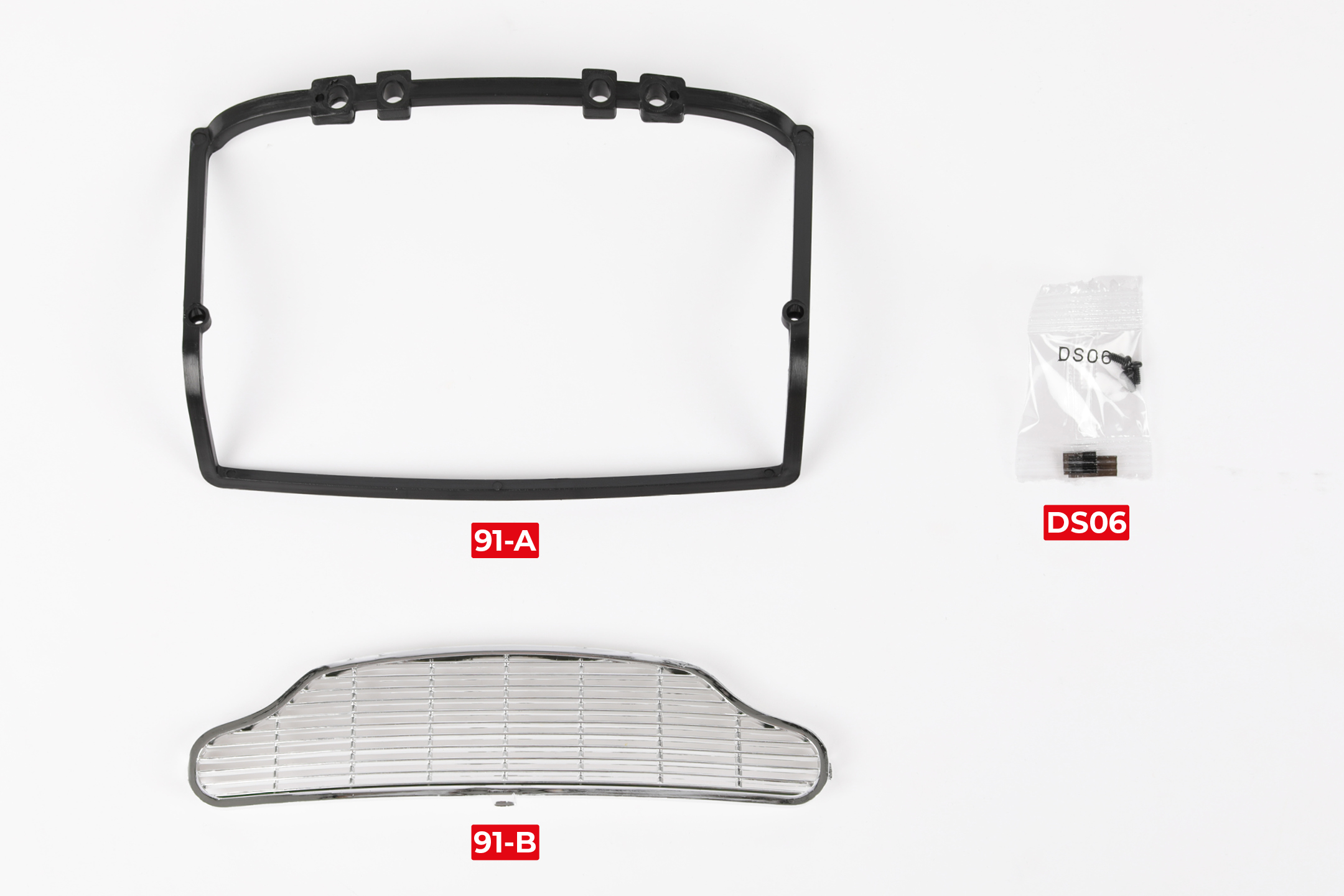
| 91-A Boot lid frame |
| 91-B Front grille |
| 3x DS06 screws |
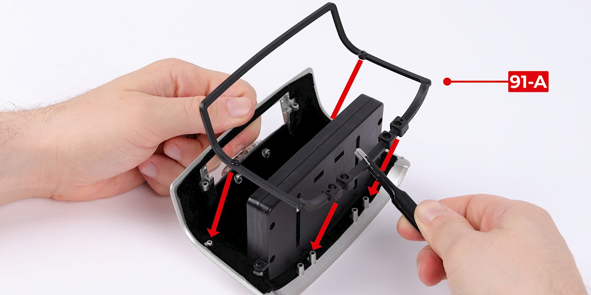
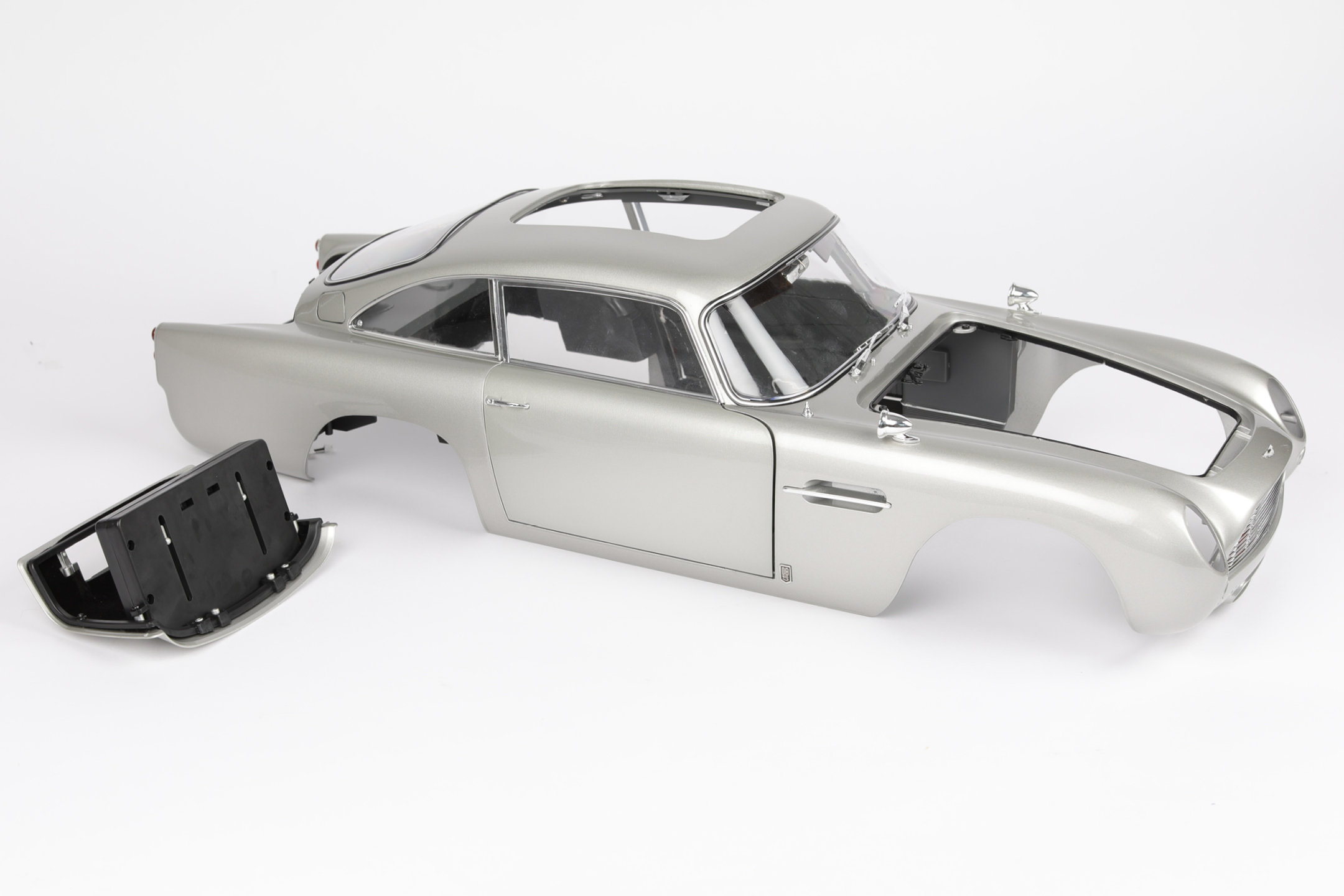
Step 1
Fit the boot lid frame (91-A) to the boot lid assembly (stage 90).
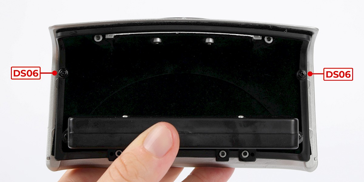
Secure with 2x DS06.
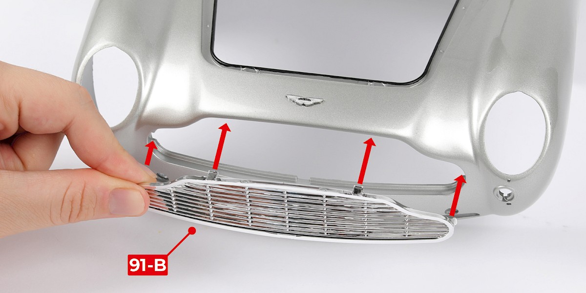
Step 2
Fit the front grille (91-B) to the main body (stage 89).
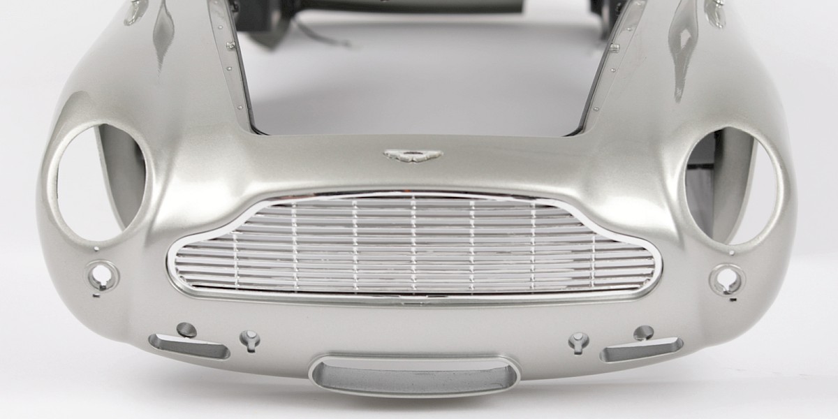
STAGE COMPLETE
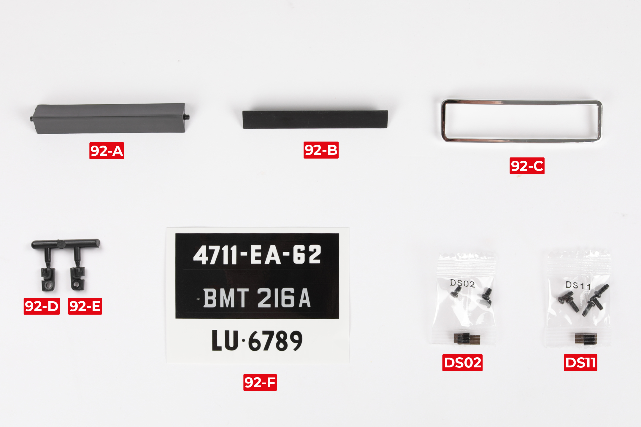
PARTS LIST
| 92-A Number plate | 92-E Retainer tab (L) |
| 92-B Number plate insert | 92-F Registration stickers |
| 92-C Number plate frame | 3x DS02 screws |
| 92-D Retainer tab (R) | 5x DS11 screws |
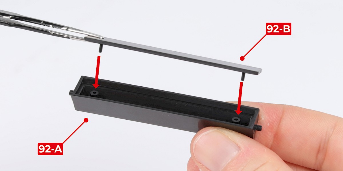
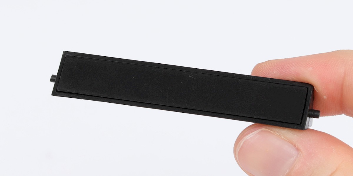
Step 1
Fit the number plate insert (92-B) onto the number plate (92-A).
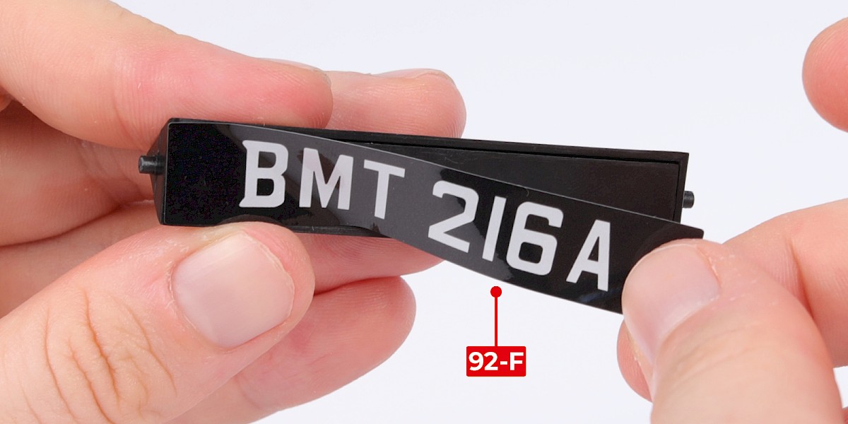
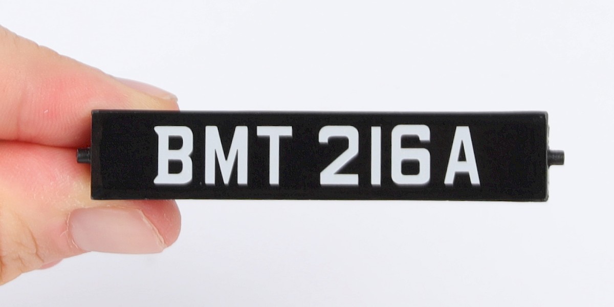
Step 2
Peel the BMT 216A sticker from the registration stickers (92-F) and stick it to the assembly.
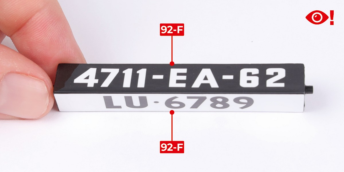
Step 3
Stick the other two registration stickers to the assembly. Make sure to stick the stickers in the same orientation.
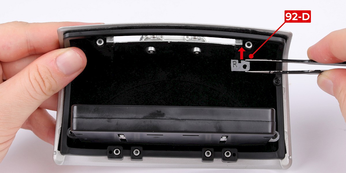
Step 4
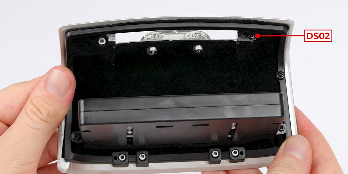
Fit the right retainer tab (92-D), marked "R", to the boot lid (stage 91).
Secure with 1x DS02.
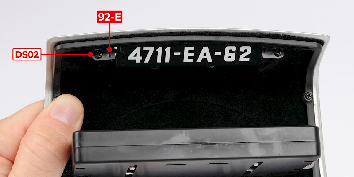
Step 5
Insert the pivots of the number plate into the recesses.
Then fit the left retainer tab (92-E), marked "L", in place. Secure with 1x DS02.

Step 6
Fit the number plate frame (92-C) to the assembly.
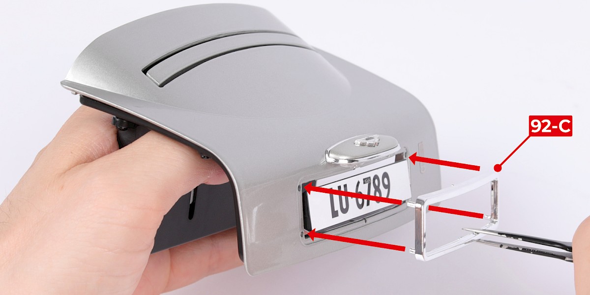
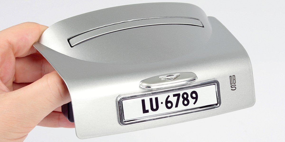
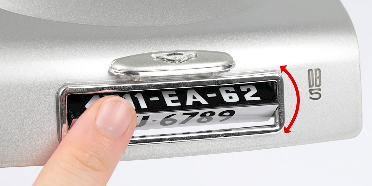
Step 7
You can rotate the number plate to switch between the different registrations.
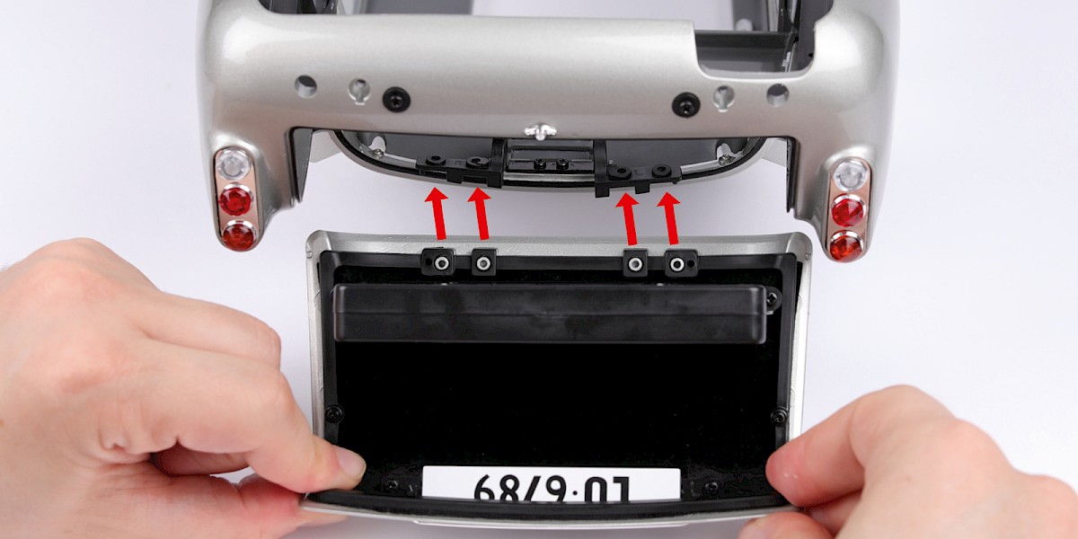
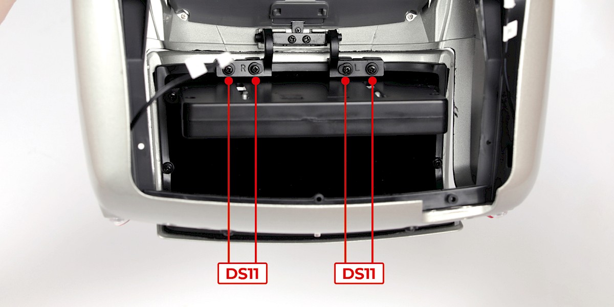
Step 8
Fit the assembly to the main body (stage 91).
Secure with 4x DS11.
Step 9
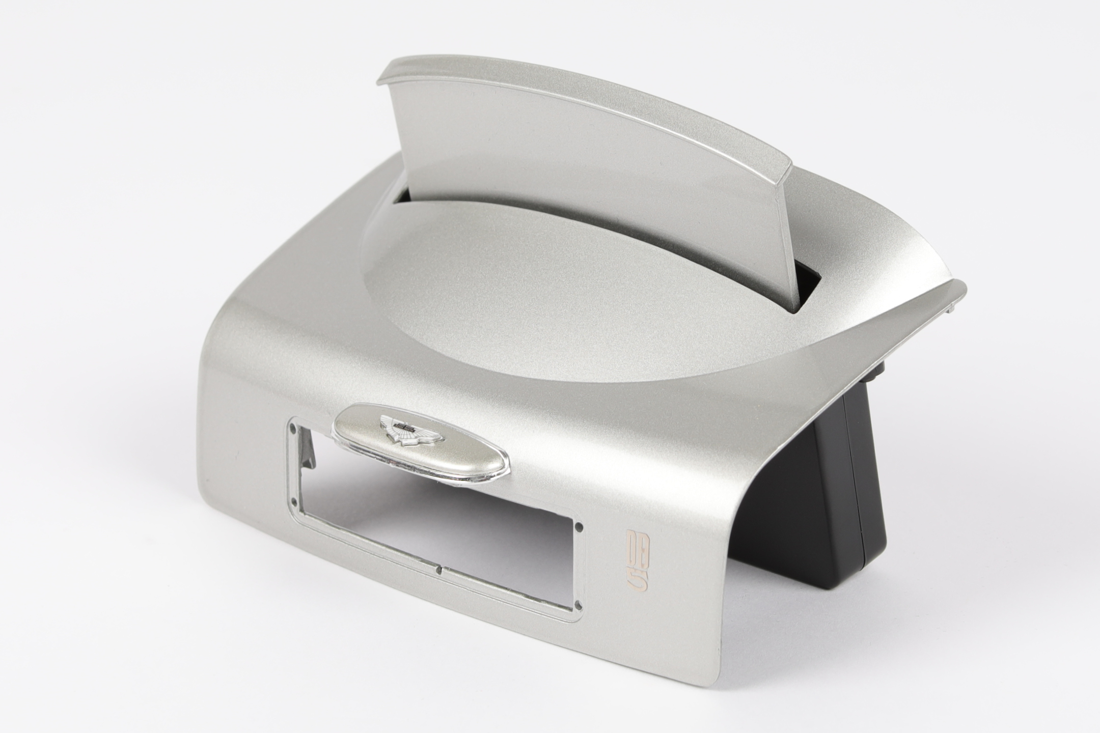
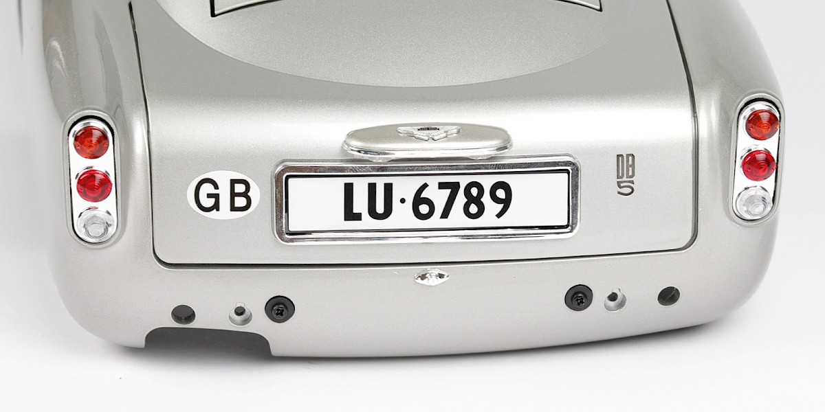
Stick the GB sticker (90-D), supplied with stage 090, to the assembly.
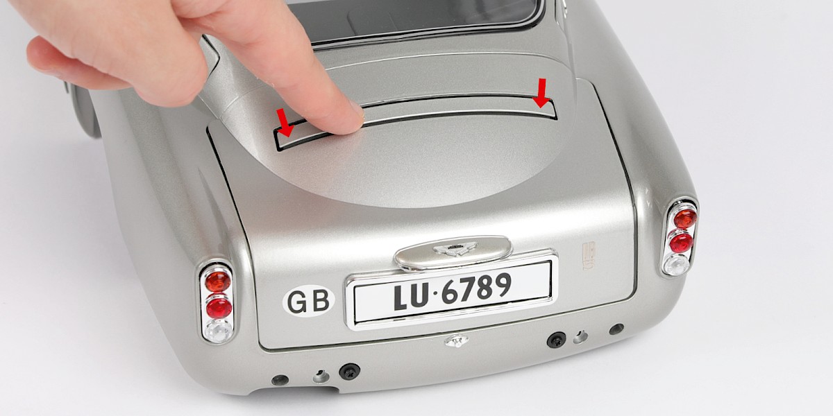
Step 10
Deploy the bulletproof screen by pushing it downward.
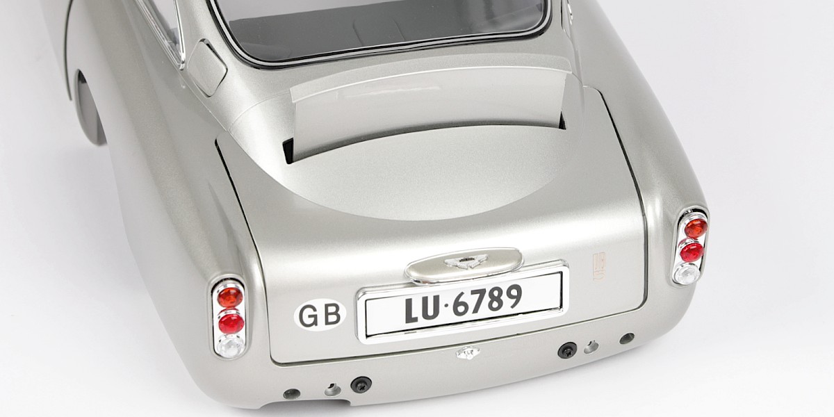
STAGE COMPLETE