

Pack 12
BUILD INSTRUCTIONS
Advice from the experts
Spare screws are included with each part. Occasionally, you may be instructed to keep spare or unused screws for a later stage. Keep these spares in a safe place and label them correctly.
Please make sure you don’t mix up the screws. They look quite similar, but the threads do vary slightly. Using the wrong screws may damage the parts. Only use the correct size screwdriver that fits the screw head firmly.
When securing parts together using multiple screws, fit each screw loosely to ensure all the parts are correctly aligned before gently tightening them firmly, but not overtight, in the order in which you placed them.
The screwdriver can be magnetized by stroking it with a magnet (fridge magnet, etc.) enabling it to hold the screws and make assembly easier.
If a screw is tight going into a metal part, do not force it as you may shear the head off. Remove it and put a tiny smear of Vaseline, soap or light oil on the thread. That will lubricate it and make it easier to tighten.
Some parts will require a little glue for assembly. Please apply glue sparingly and use a cocktail stick so that you don’t use too much nor apply the glue too heavily. We recommend superglue gel or Extra Thin Liquid modeling glue. Where possible, parts should be test-fitted in place before gluing.
Make sure you have good ventilation when using adhesives and to replace caps firmly.
Use a magnet to help find screws that have fallen on the floor.
Use masking tape to hold parts temporarily in place.
Cut parts from a sprue (framework) with side cutters or a craft knife. Side cutters tend to be easiest.
During the course of this build, you will receive many pieces that you will assemble immediately – following the instructions in the corresponding stage – and other pieces that you should store safely to one side, for use in future assembly stages.
Always protect the paint finish on components by placing a cutting mat, sheet of white paper or soft cloth on your work surface.
When plugging cables in, ensure the power is switched off. Tweezers can be used to fit the PVC cables by gripping carefully around 5mm from the end of the cable. If a cable needs to be removed from a socket, do not pull on the cable as this could damage the connection. Grip the plug with tweezers to remove it.
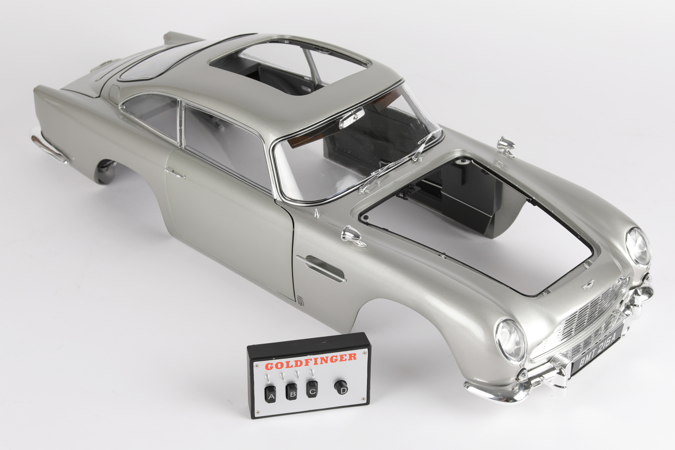
Left and Right! When building your Goldfinger DB5, the left- or right-hand side refers to that side as if you are sitting in the car.
![]() When you see this symbol, pay attention to the instruction text in bold and check the orientation of the parts in the image as this will be particularly important for assembly in later stages.
When you see this symbol, pay attention to the instruction text in bold and check the orientation of the parts in the image as this will be particularly important for assembly in later stages.
WARNING: Some parts are assembled using magnets. These magnets can cause serious injury if they are swallowed. Keep away from children. If you suspect a magnet has been swallowed, seek medical help straight away.
This is not a toy. Not suitable for children under 14 years old due to small parts. Adult supervision required.

PARTS LIST
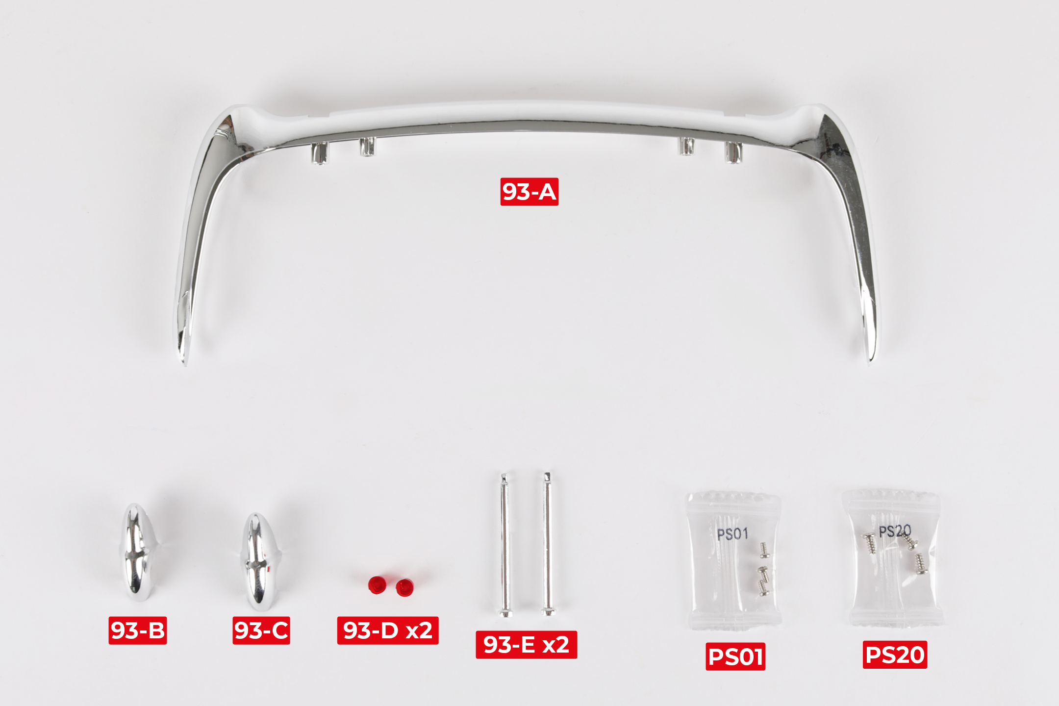
| 93-A Rear bumper | 93-E Battering ram rod x2 |
| 93-B Left battering ram (RL) | 3x PS01 screws |
| 93-C Right battering ram (RR) | 3x PS20 screws |
| 93-D Reflector x2 |
Step 1
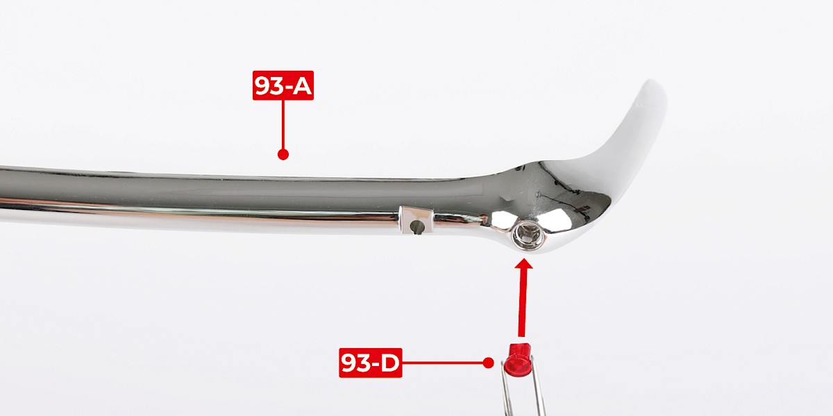
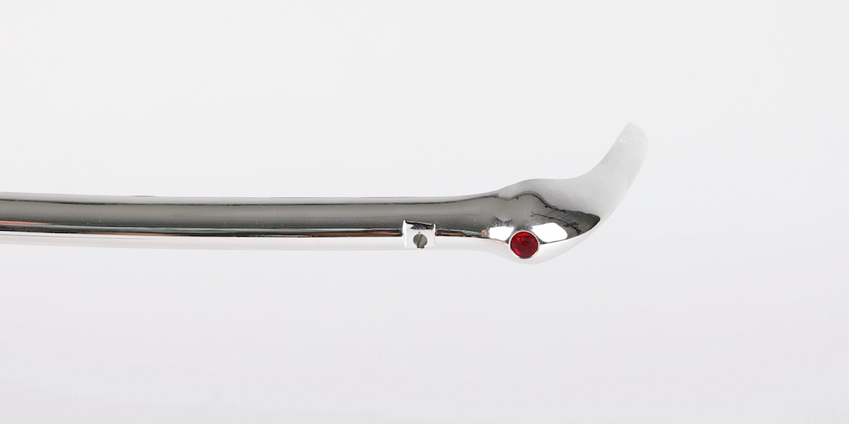
Insert a reflector (93-D) into one side of the rear bumper (93-A). The reflector is shaped so it will only fit one way.
Step 2
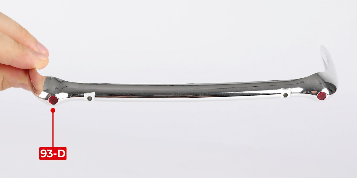
Insert the second reflector (93-D) into the other side of the rear bumper.
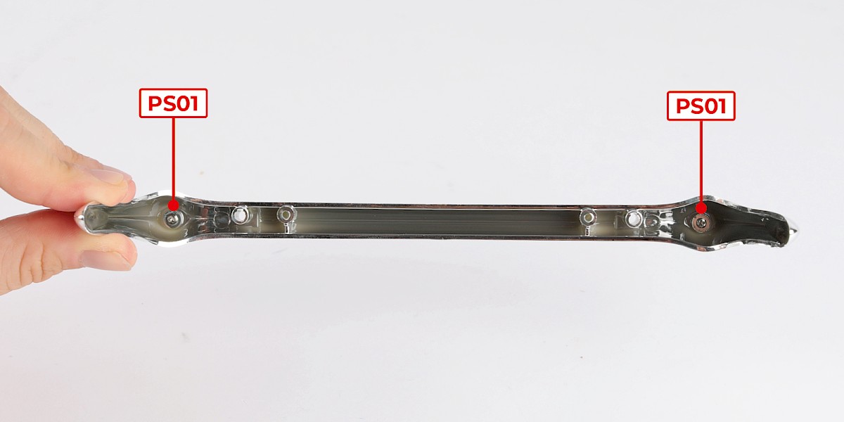
Step 3
Secure with 2x PS01.
Step 4
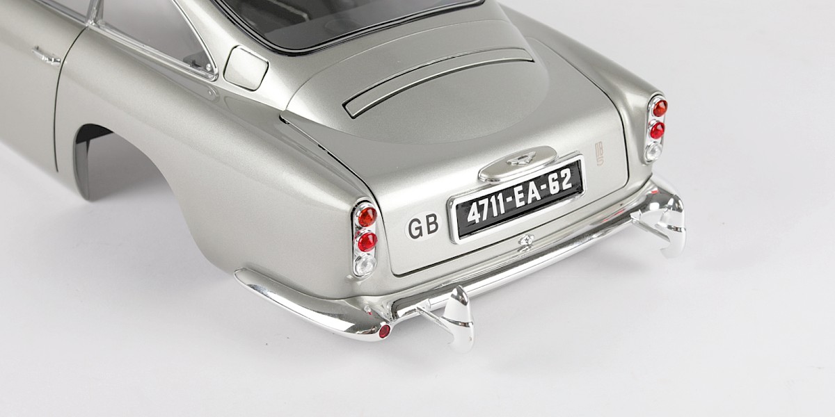
Fit the rear bumper onto the main body (stage 92).
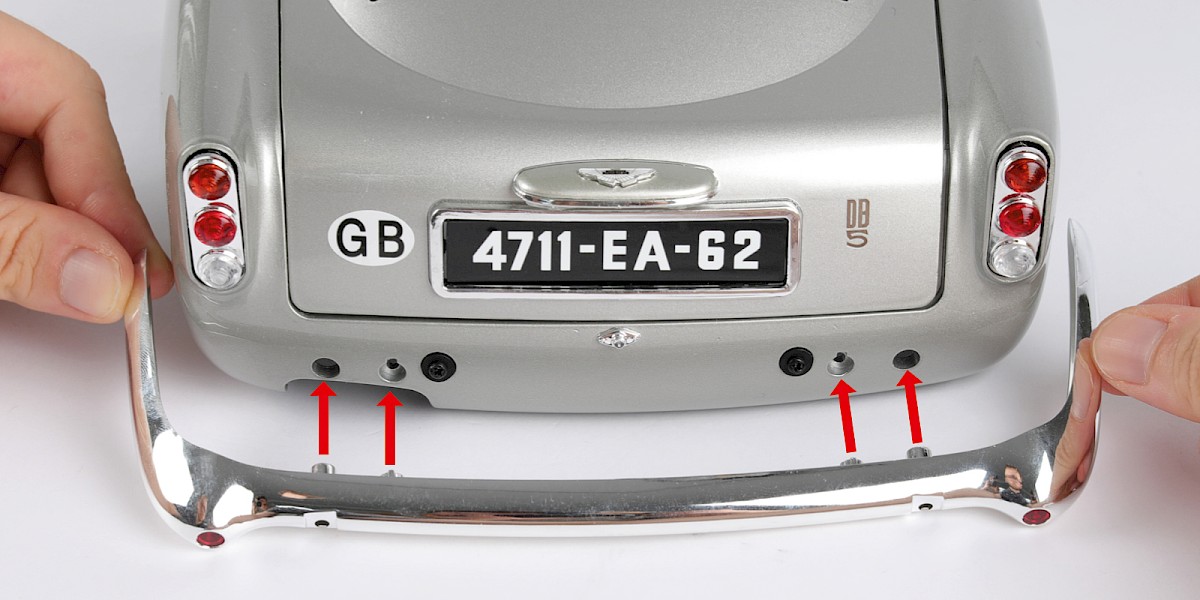
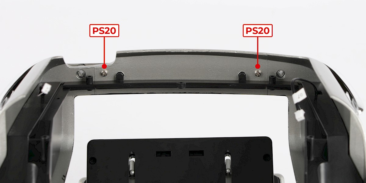
Step 5
Secure with 2x PS20.
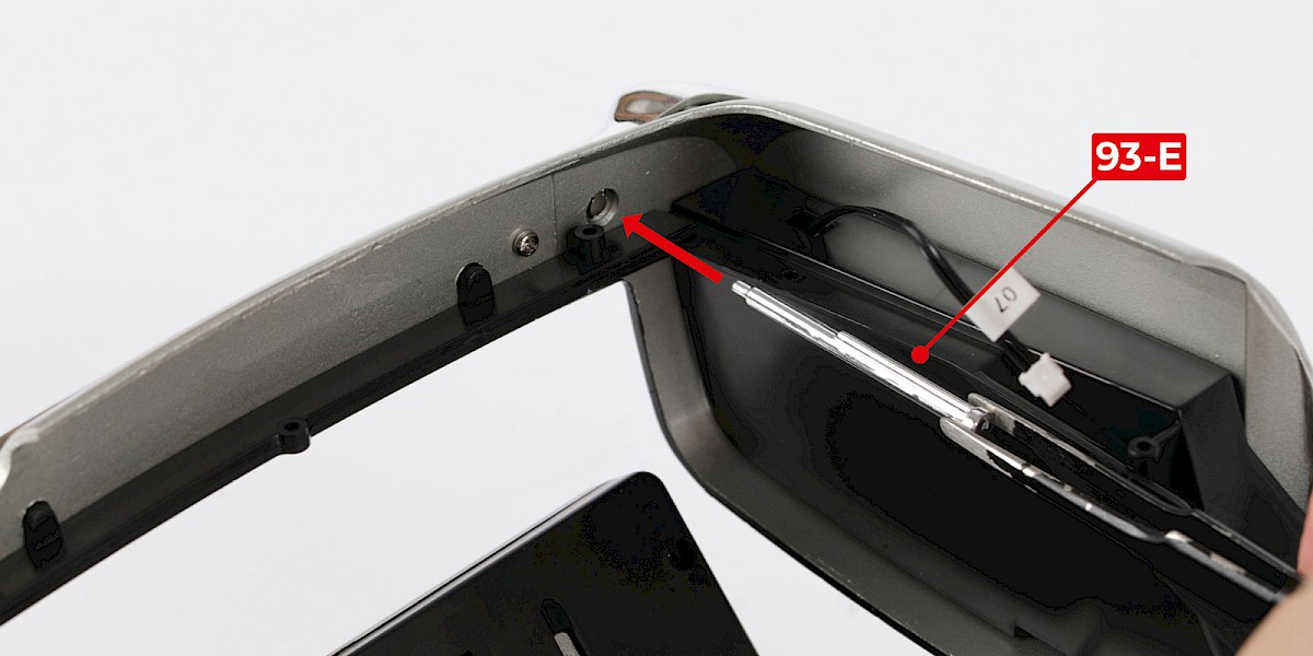
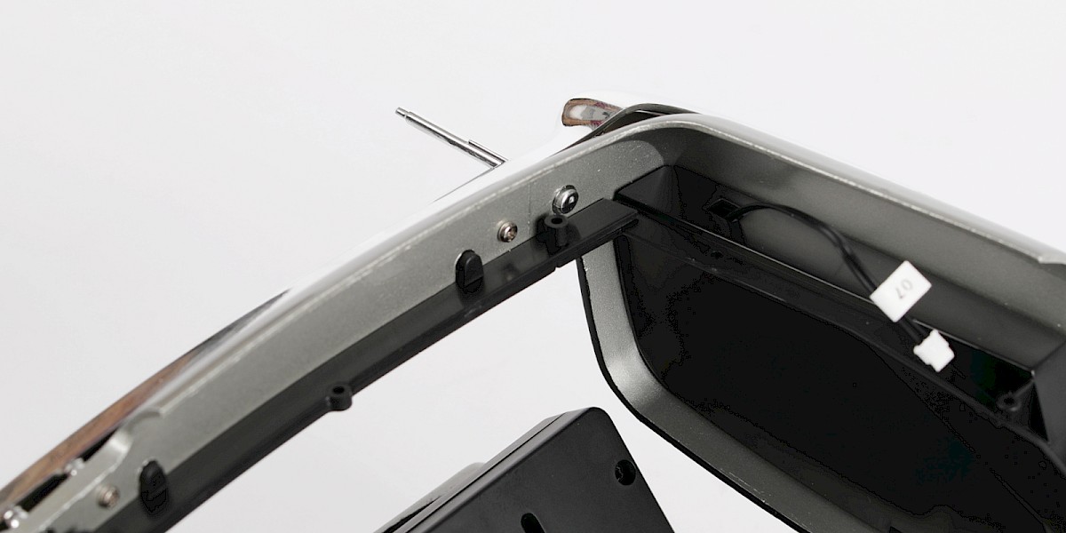
Step 6
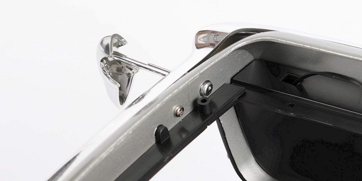
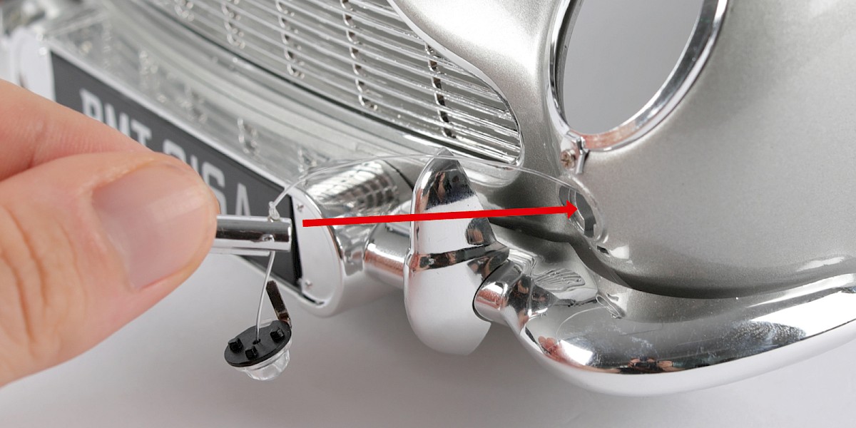
Insert a battering ram rod (93-E) through the hole in the rear bumper.
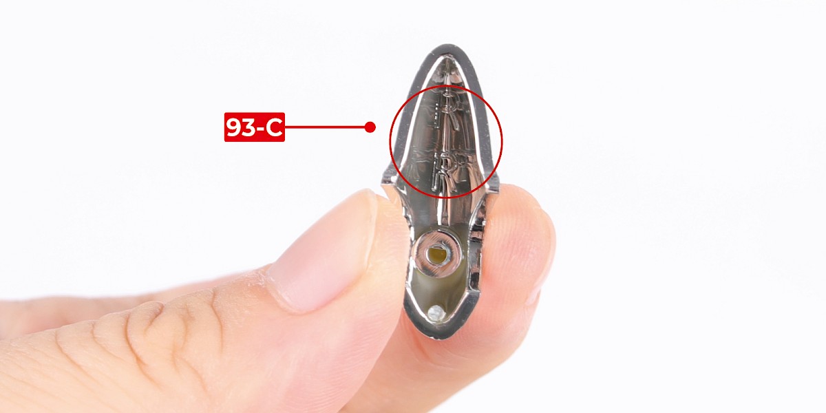
Step 7
Take the right battering ram (93-C), marked with RR.
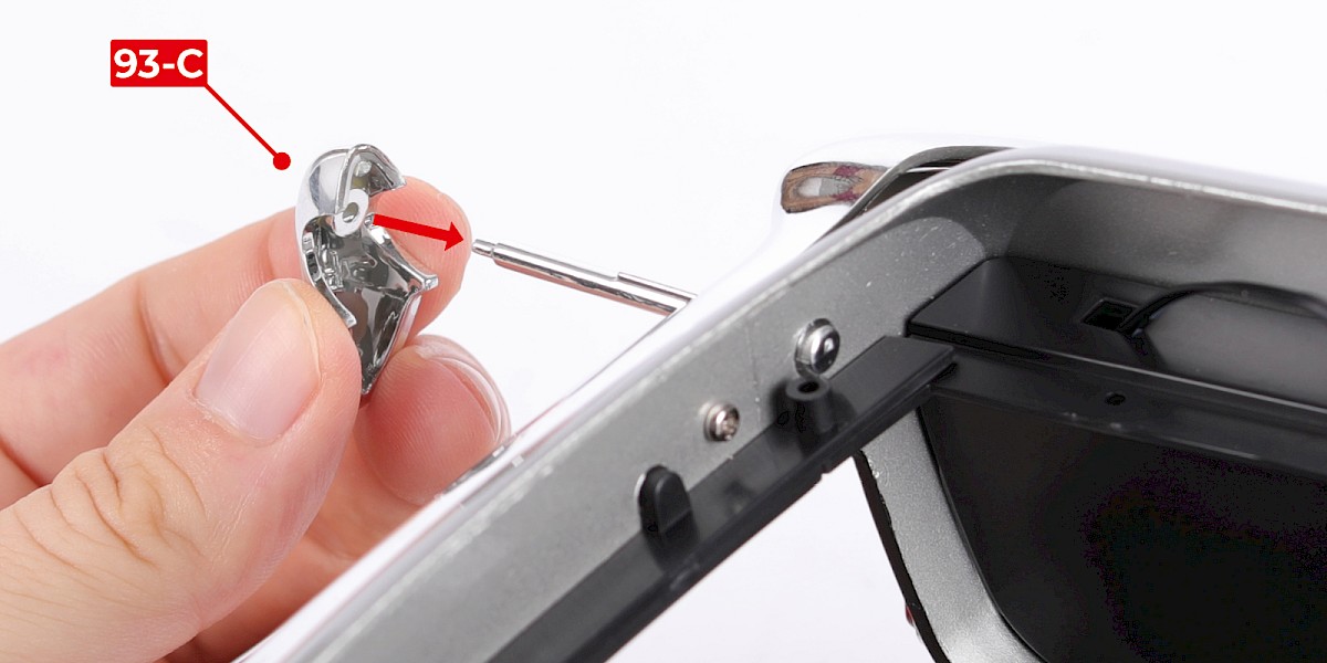
Step 8
Fit the right battering ram (93-C) to the battering ram rod. The parts are shaped so they can only fit one way.
Step 9
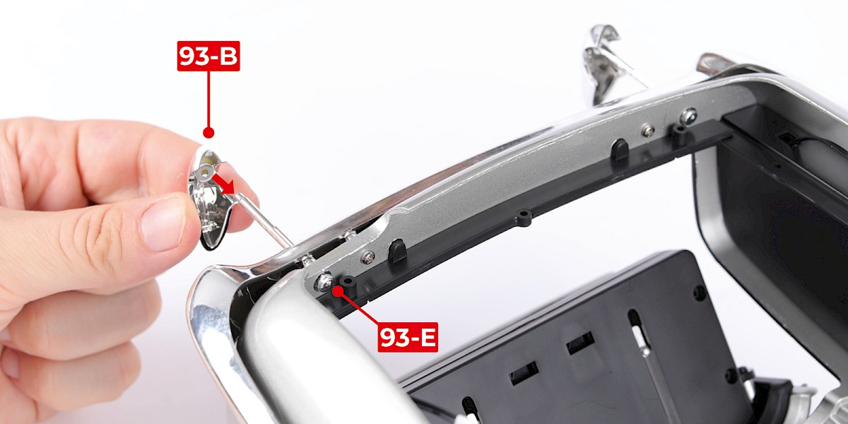
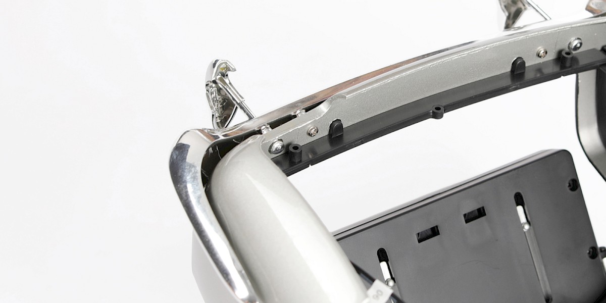
Insert the second battering ram rod (93-E) through the other hole in the rear bumper, then fit the battering ram (93-B) in the same way.
Step 10
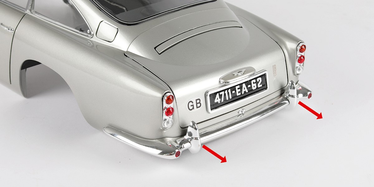
The battering rams can be pulled out from the bumper.
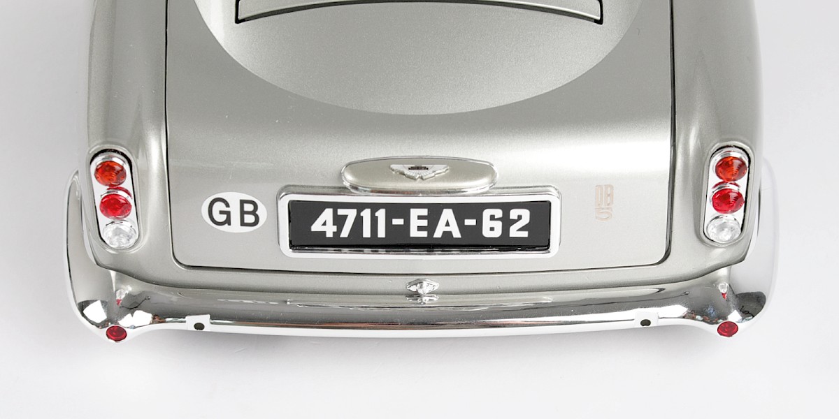
STAGE COMPLETE
PARTS LIST
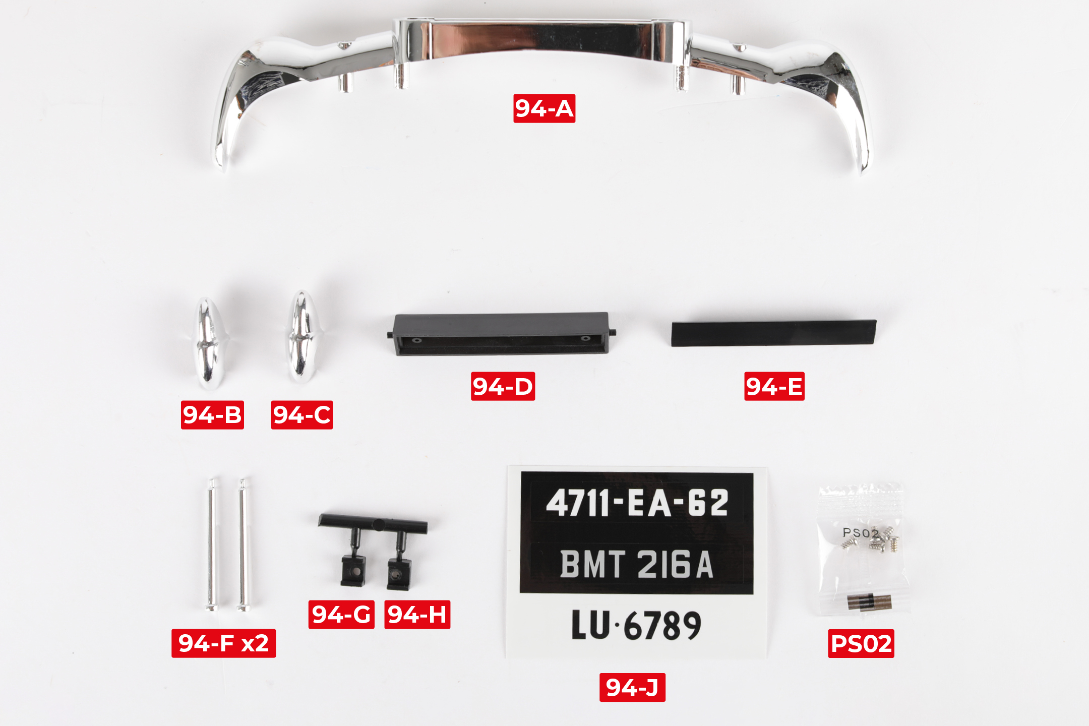
| 94-A Front bumper | 94-F Battering ram rod x2 |
| 94-B Left battering ram (FL) | 94-G Retainer tab |
| 94-C Right battering ram (FR) | 94-H Retainer tab |
| 94-D Number plate | 94-J Registration sticker sheet |
| 94-E Number plate insert | 5x PS02 screws |
Step 1
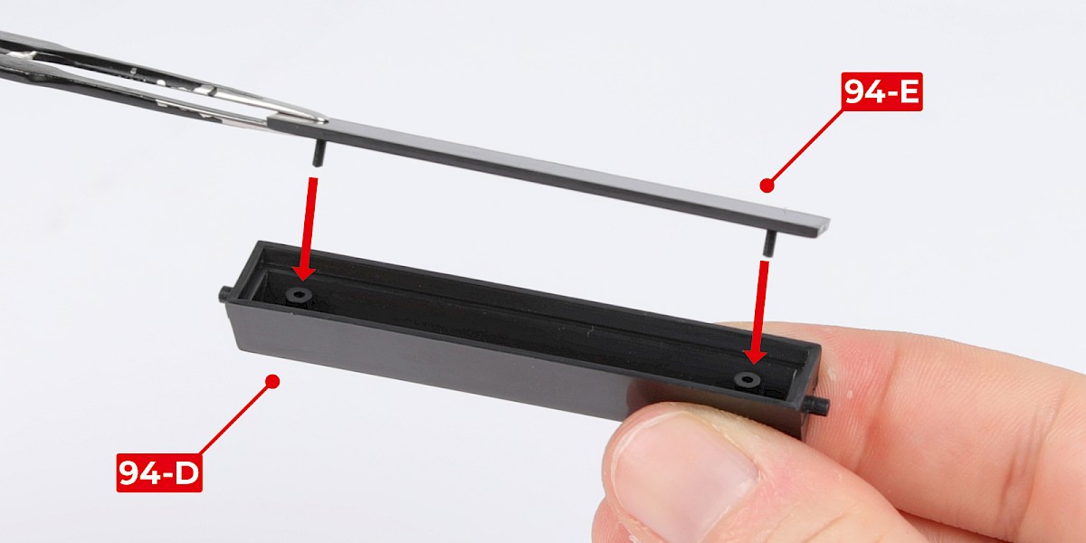
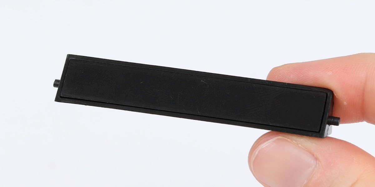
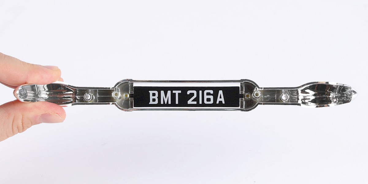
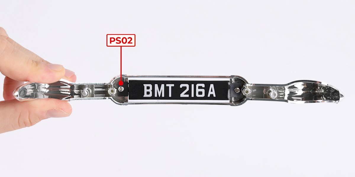
Fit the number plate insert (94-E) onto the number plate (94-D).
Step 2
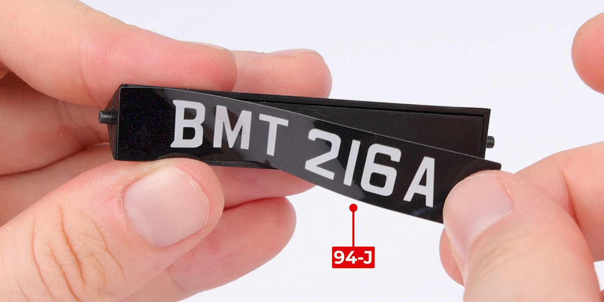
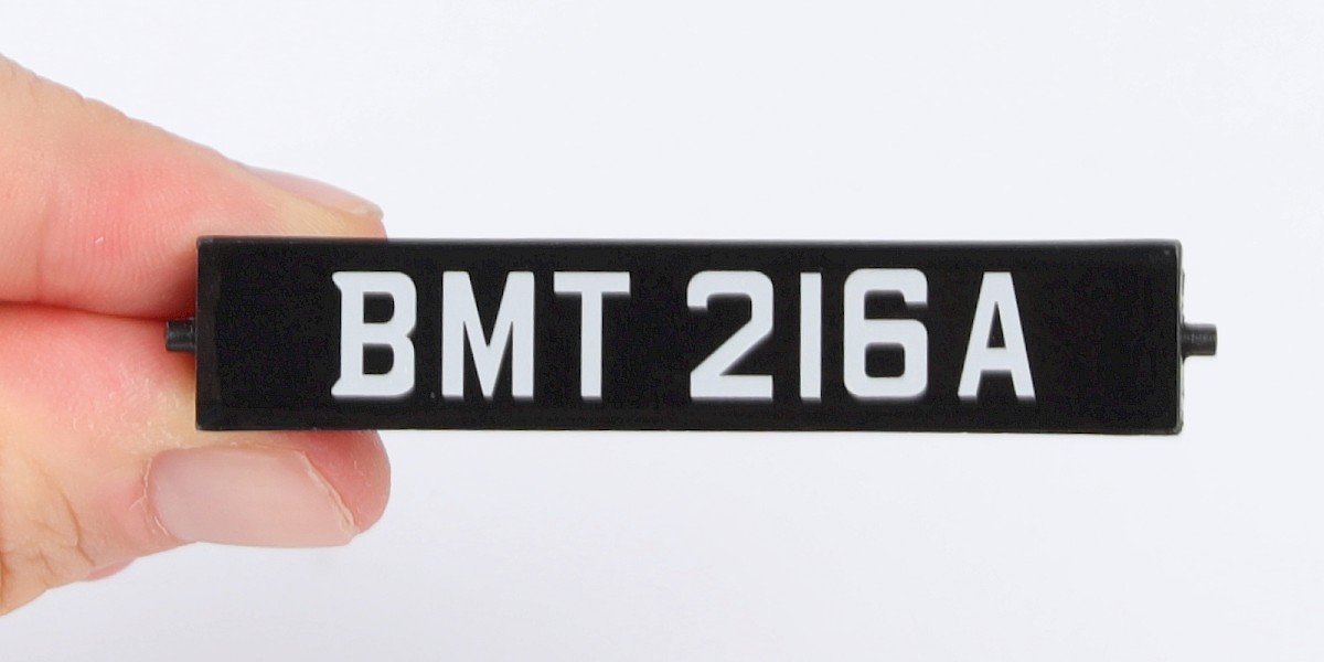
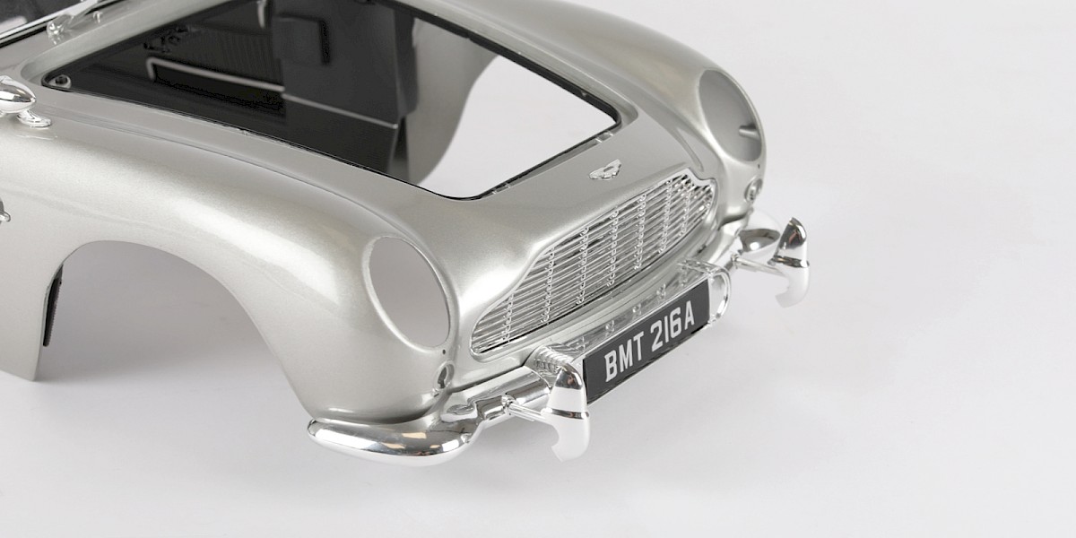
Peel the BMT 216A sticker from the registration sticker sheet (94-J) and stick it to the assembly.
Step 3
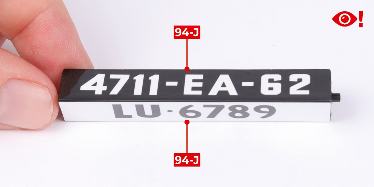
Stick the other two registration stickers to the assembly. Make sure the stickers are positioned in the same orientation.
Step 4
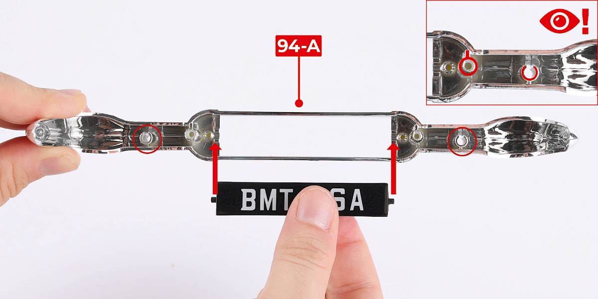
Fit the number plate to the front bumper (94-A). Holding the bumper in the orientation shown, the two holes (circled) must be closer to the lower edge of the bumper.
Step 5
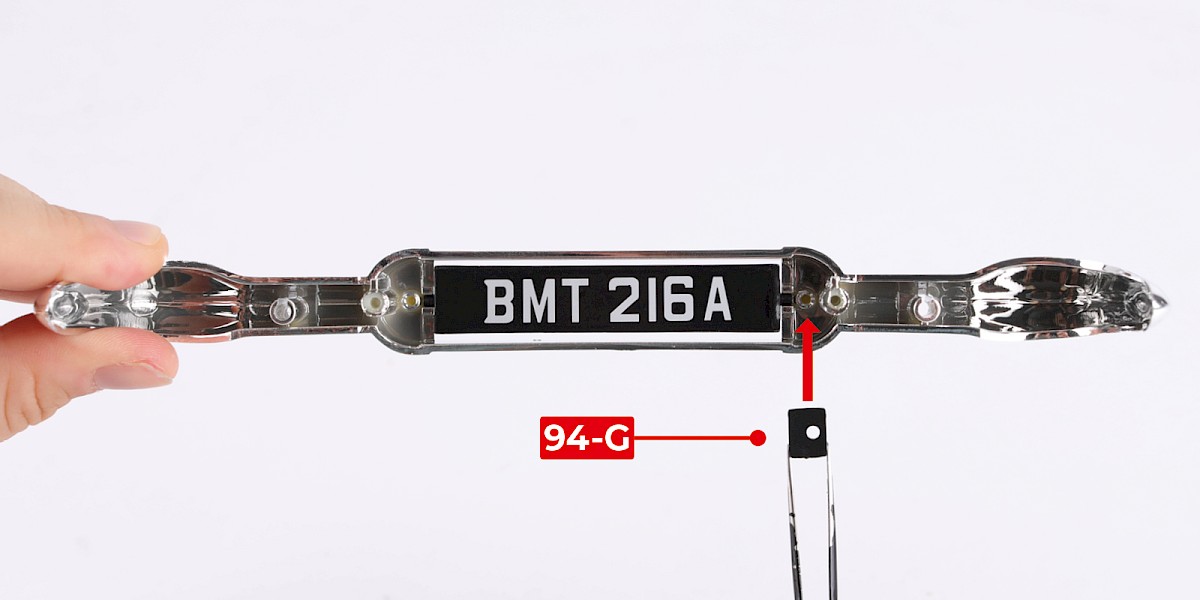
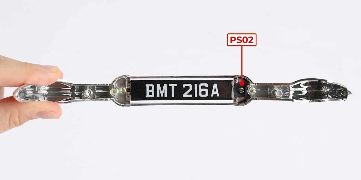
Fit a retainer tab (94-G) to the assembly then secure with 1x PS02.
Note: the retainer tabs (94-G and 94-H) are identical.
Step 6
Fit the other retainer tab (94-H) to the assembly then secure with 1x PS02.
Step 7
Turn the bumper the right way up. Fit the bumper to the main body.
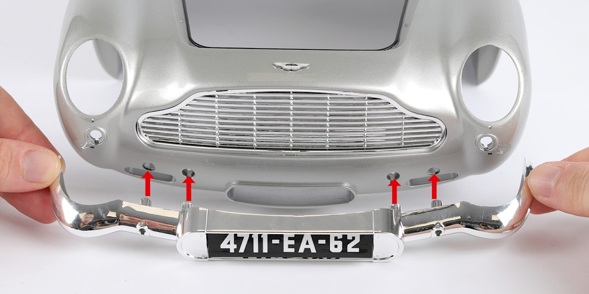
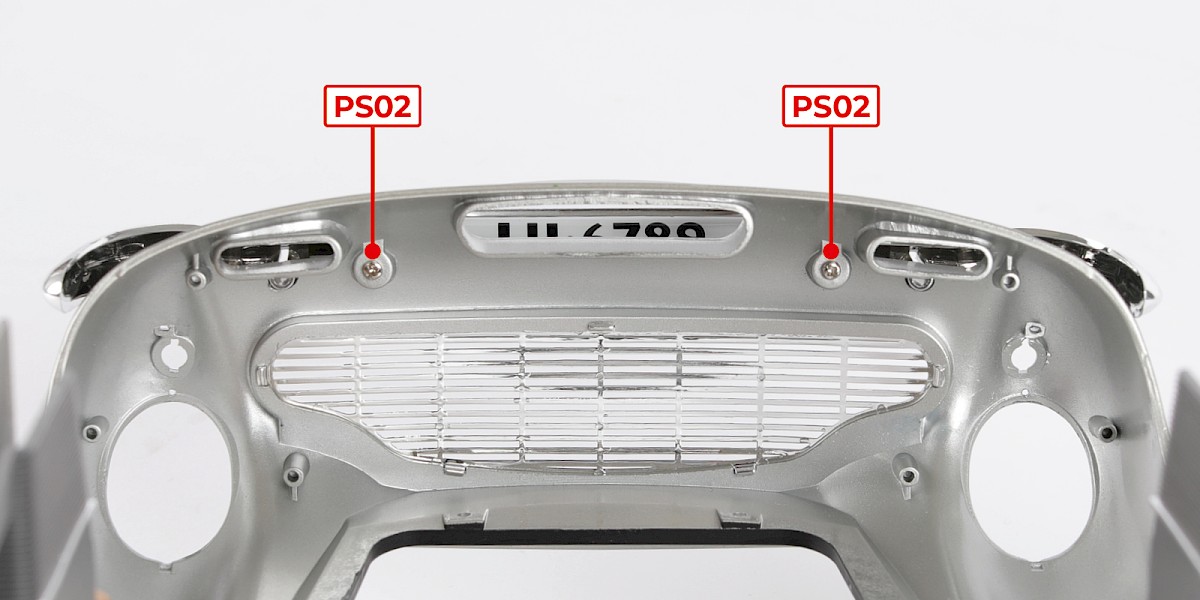
Step 8
Secure with 2x PS02.
Step 9
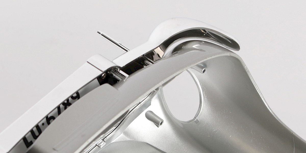
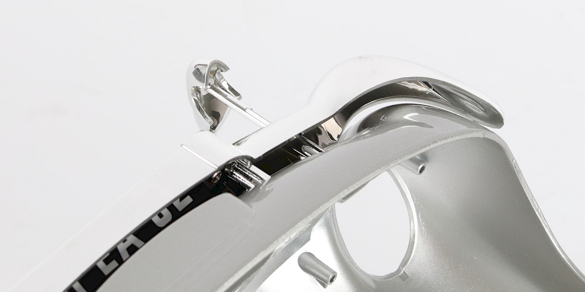
Insert a battering ram rod through the hole (94-F) in the front bumper.
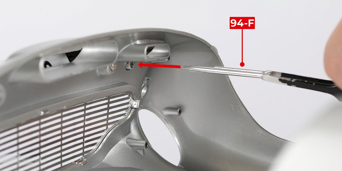
Step 10
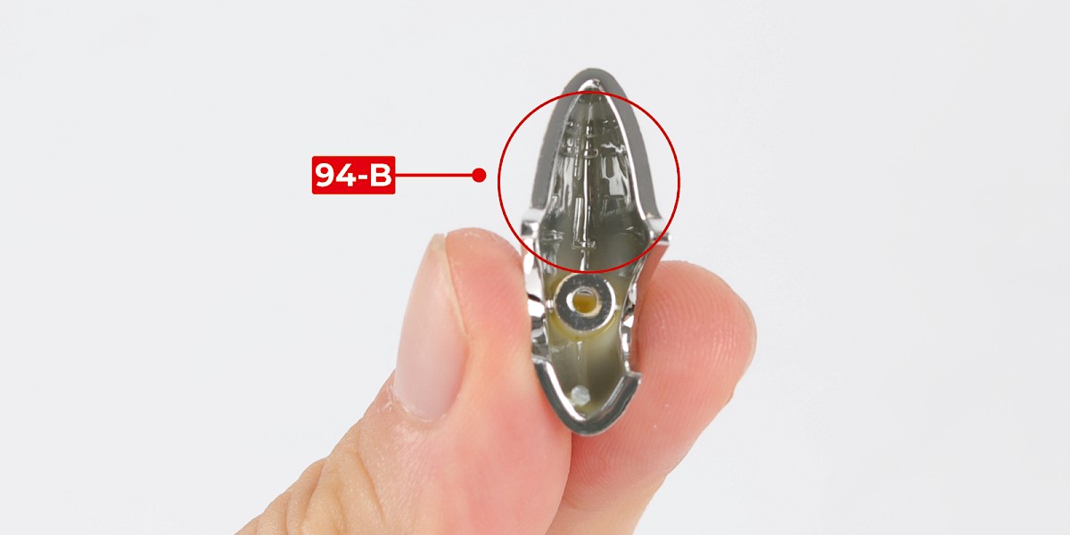
Take the left battering ram (94-B), marked with FL.
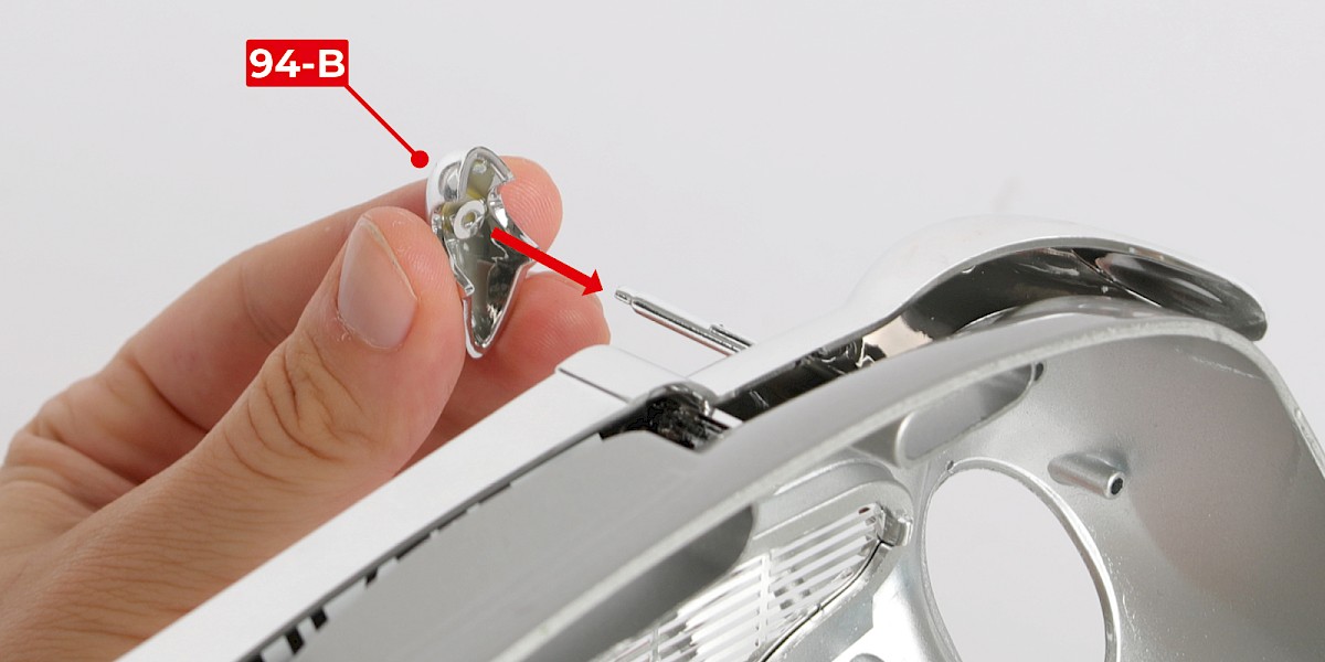
Step 11
Fit the left battering ram (94-B) to the battering ram rod. The parts are shaped so they can only fit one way.
Step 12
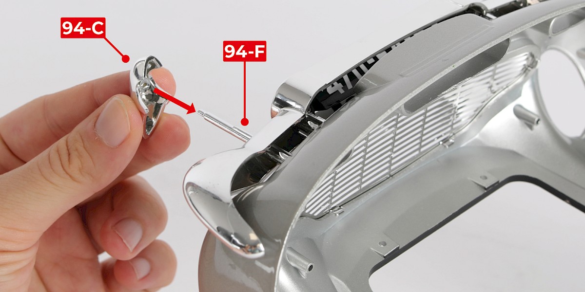
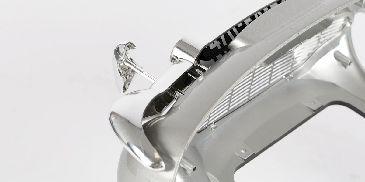
Insert the second battering ram rod (94-F) through the other hole in the front bumper, then fit the right battering ram (94-C, marked FR) to the battering ram rod.
Step 13
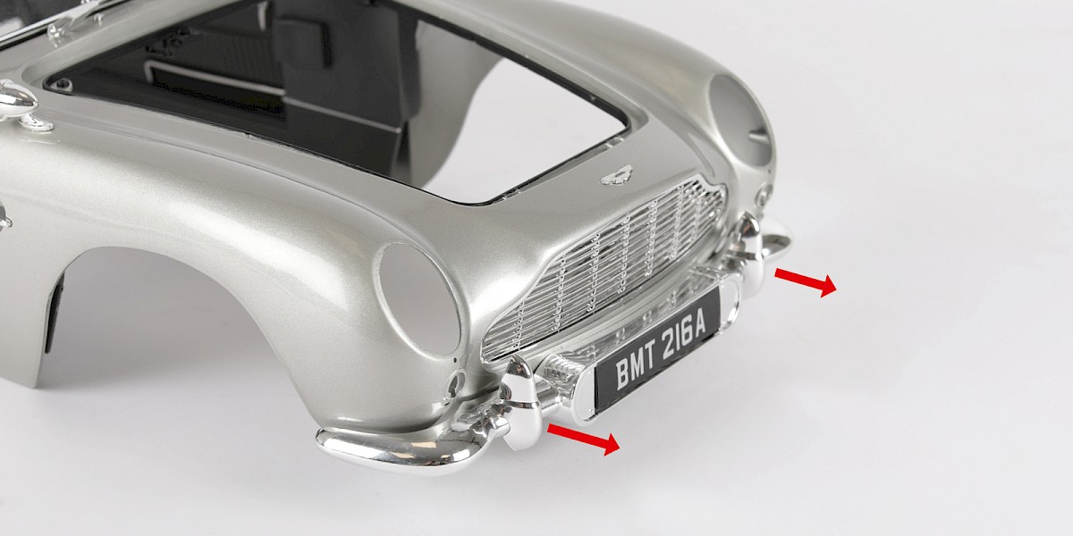
The battering rams can be pulled out from the bumper.
STAGE COMPLETE
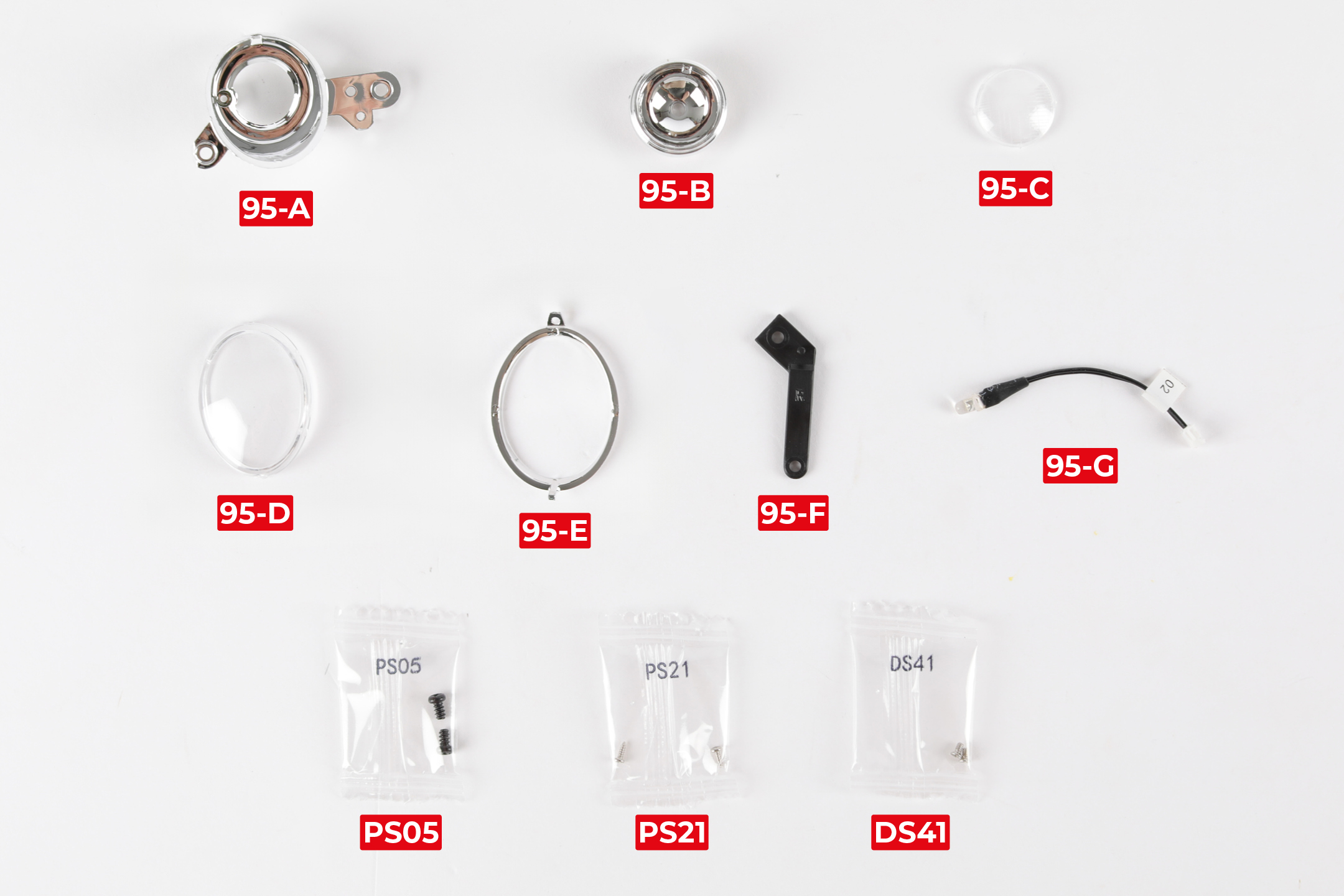
PARTS LIST
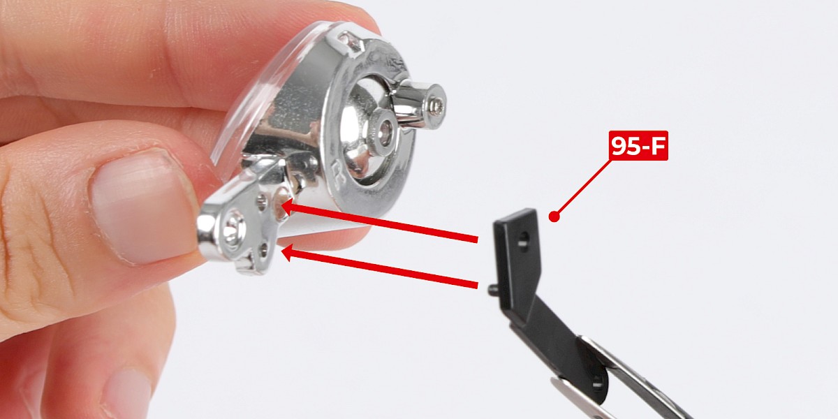
| 95-A Headlight housing (R) | 95-F Machine gun brace |
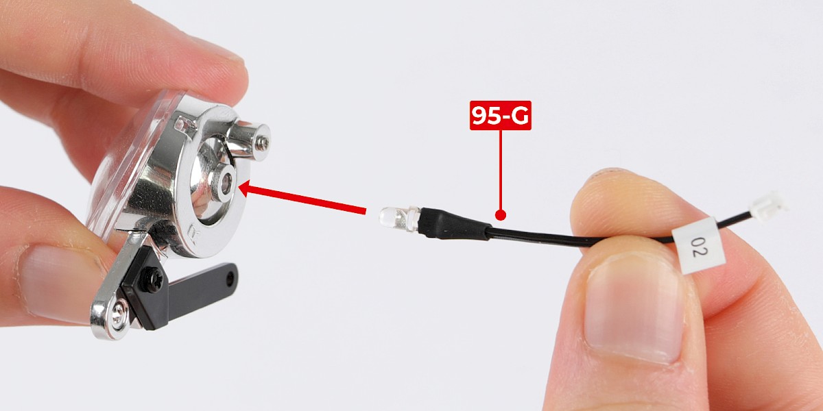
| 95-B Headlight reflector | 95-G Headlight LED |
| 95-C Headlight lens | 2x PS05 screws |
| 95-D Headlight cover | 2x PS21 screws |
| 95-E Headlight bezel | 2x DS41 screws |
Step 1
Fit the headlight lens (95-C) onto the reflector (95-B).


Step 2
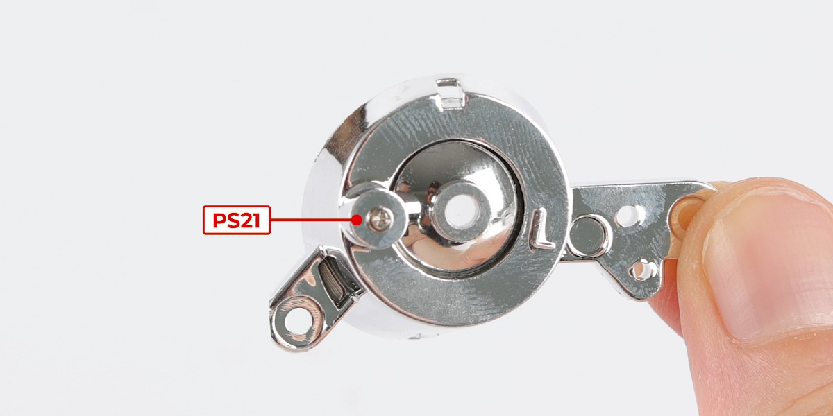
Fit the reflector into the headlight housing (95-A).
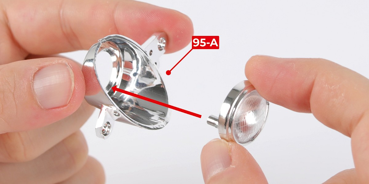
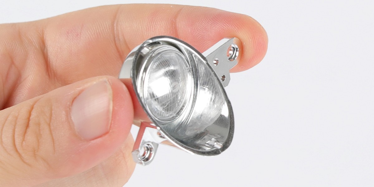
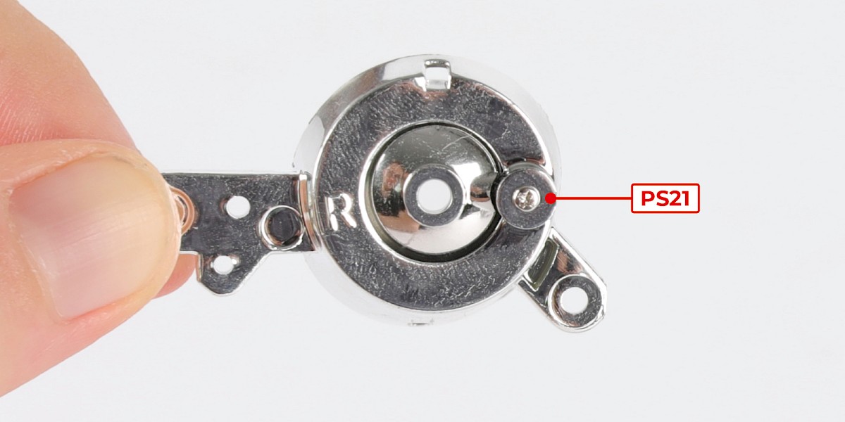
Step 3
Secure with 1x PS21.
Step 4
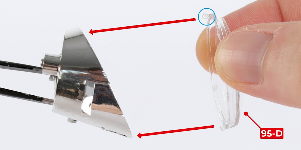
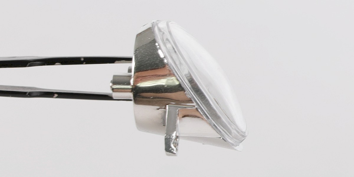
Fit the headlight cover (95-D) onto the headlight housing.
Note that the tabs are different sizes. The large tab (circled) fits onto the top of the housing.
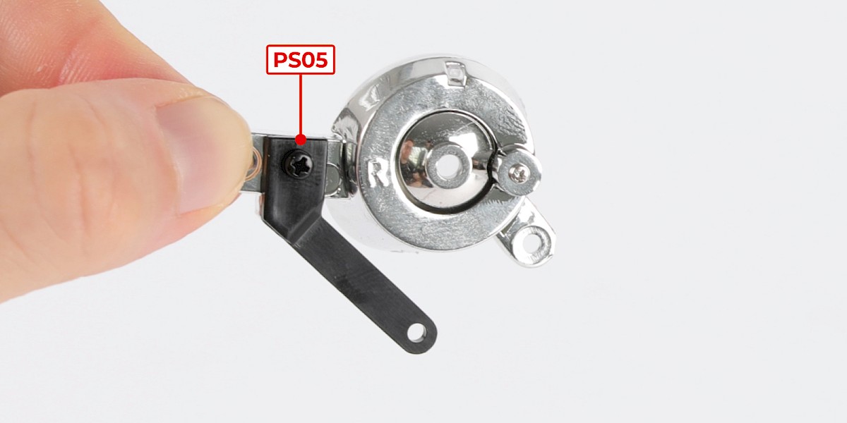
Step 5
Fit the machine gun brace (95-F) to the assembly, then secure with 1x PS05.
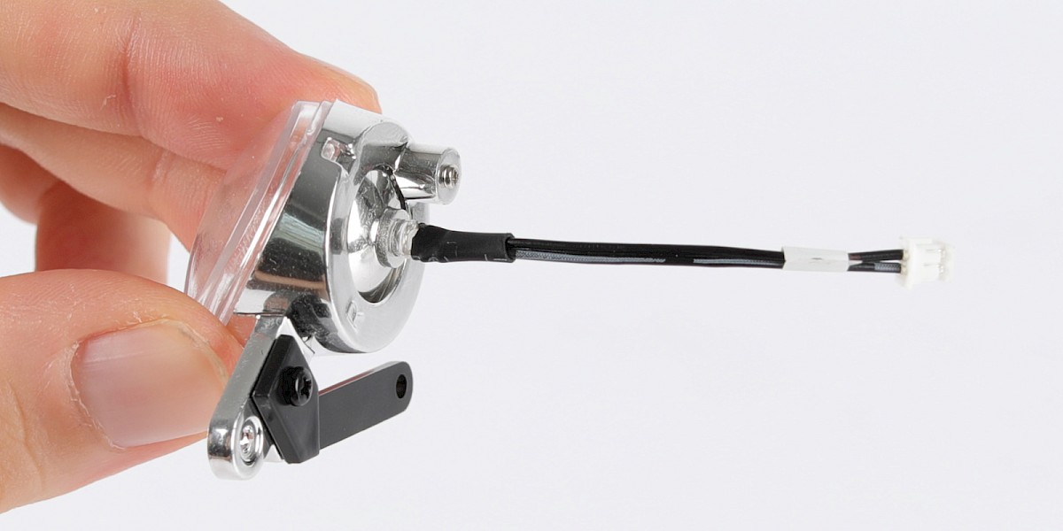
Step 6
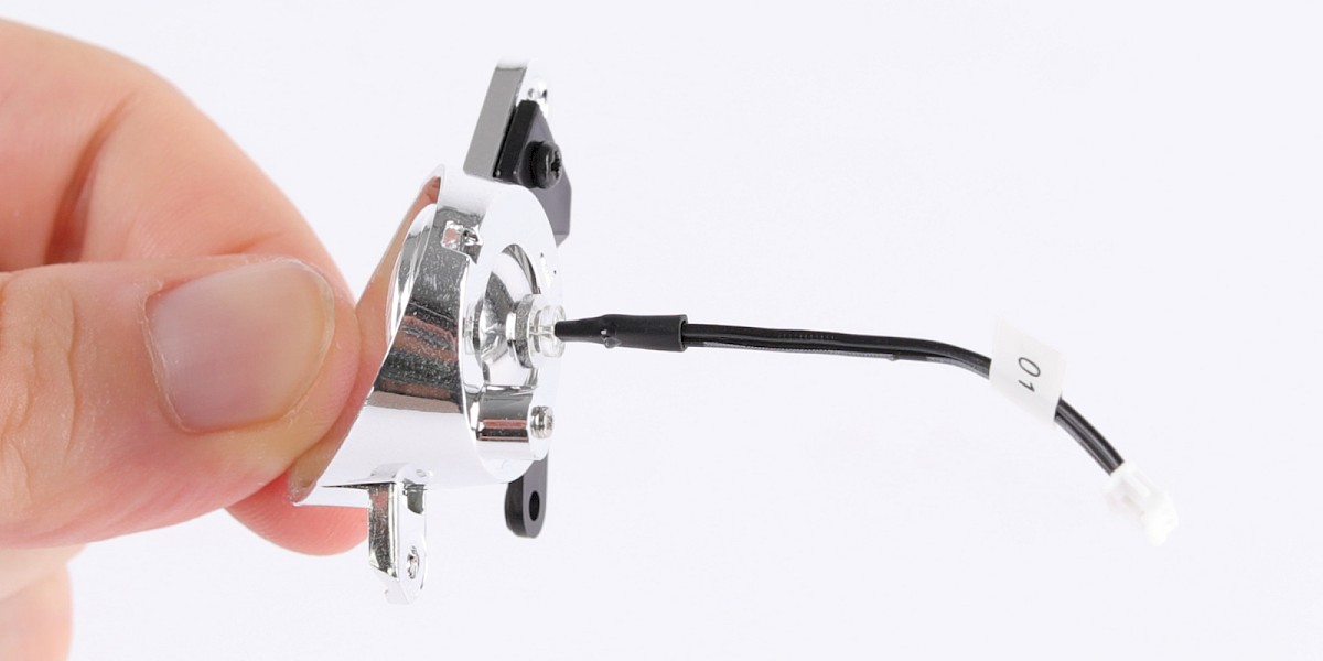
Fit the headlight LED (95-G) into the reflector.
Step 7
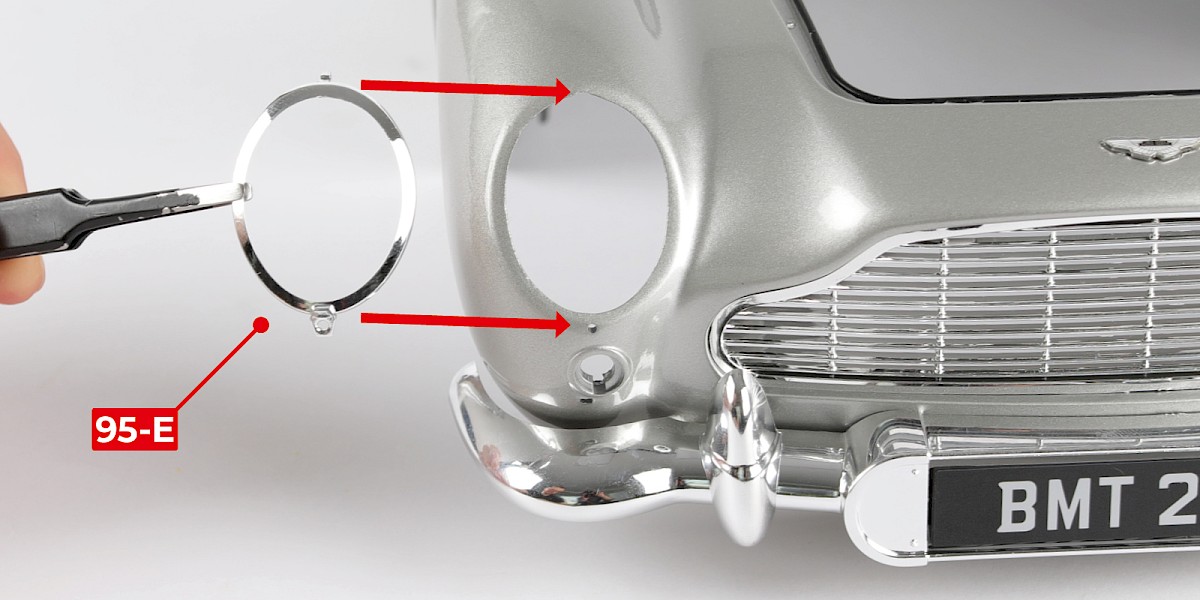
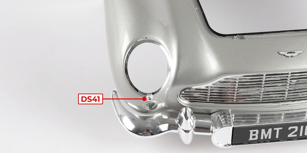
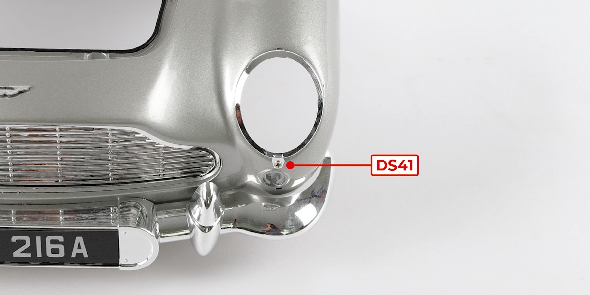
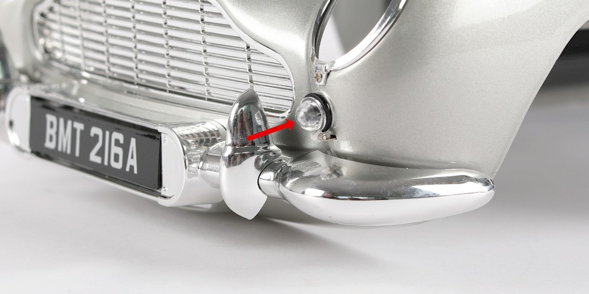
Fit the headlight bezel (95-E) to the main body (stage 94), then secure with 1x DS41.
STAGE COMPLETE
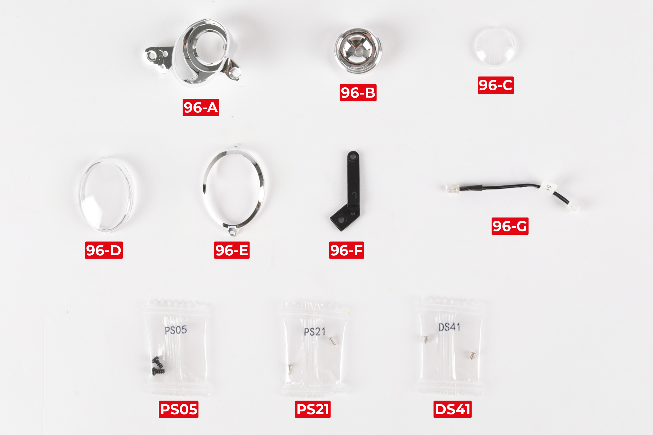
PARTS LIST
| 96-A Headlight housing (L) | 96-F Machine gun brace |
| 96-B Headlight reflector | 96-G Headlight LED |
| 96-C Headlight lens | 2x PS05 screws |
| 96-D Headlight cover | 2x PS21 screws |
| 96-E Headlight bezel | 2x DS41 screws |
Step 1
Fit the headlight lens (96-C) onto the reflector (96-B).
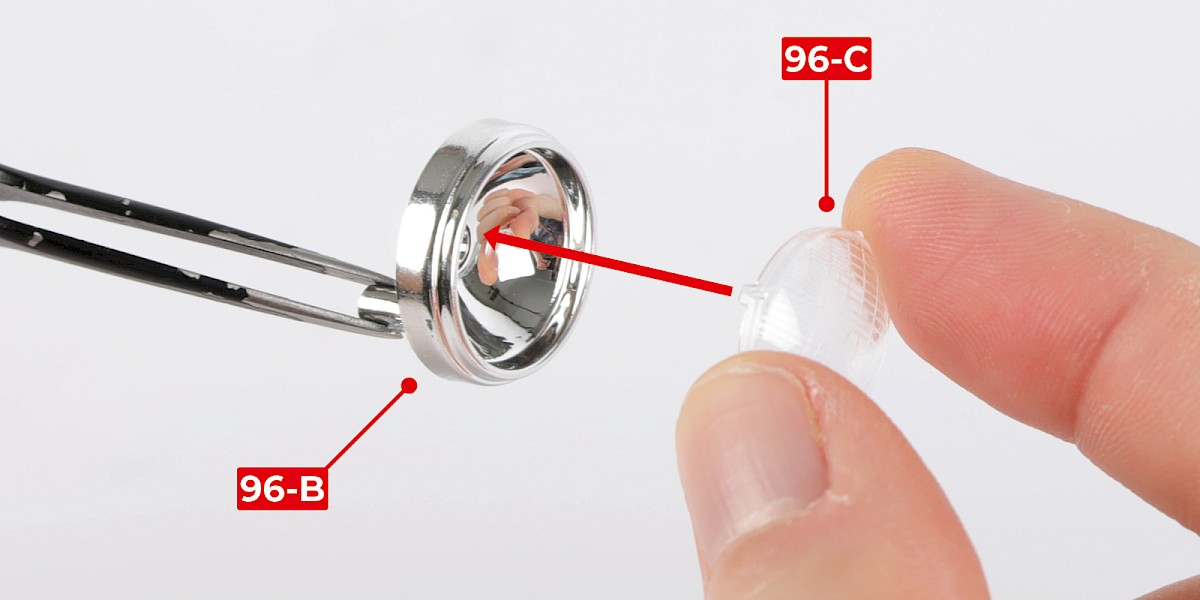
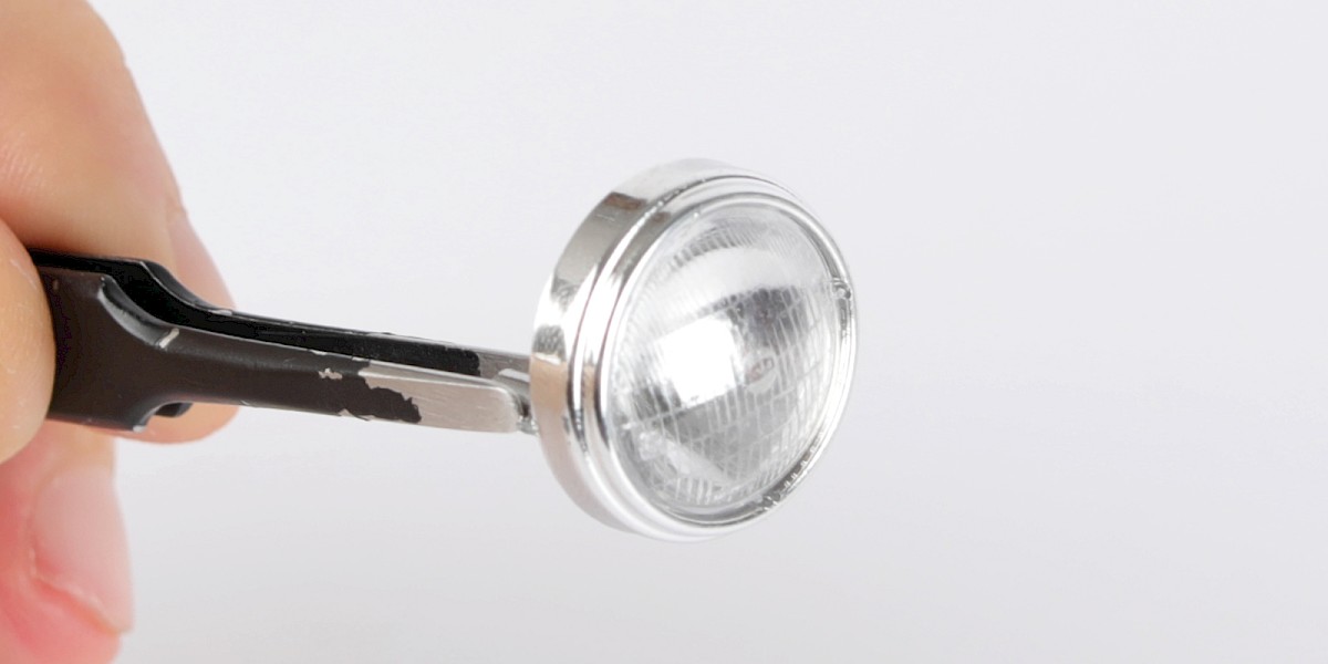
Step 2
Fit the reflector into the headlight housing (96-A).
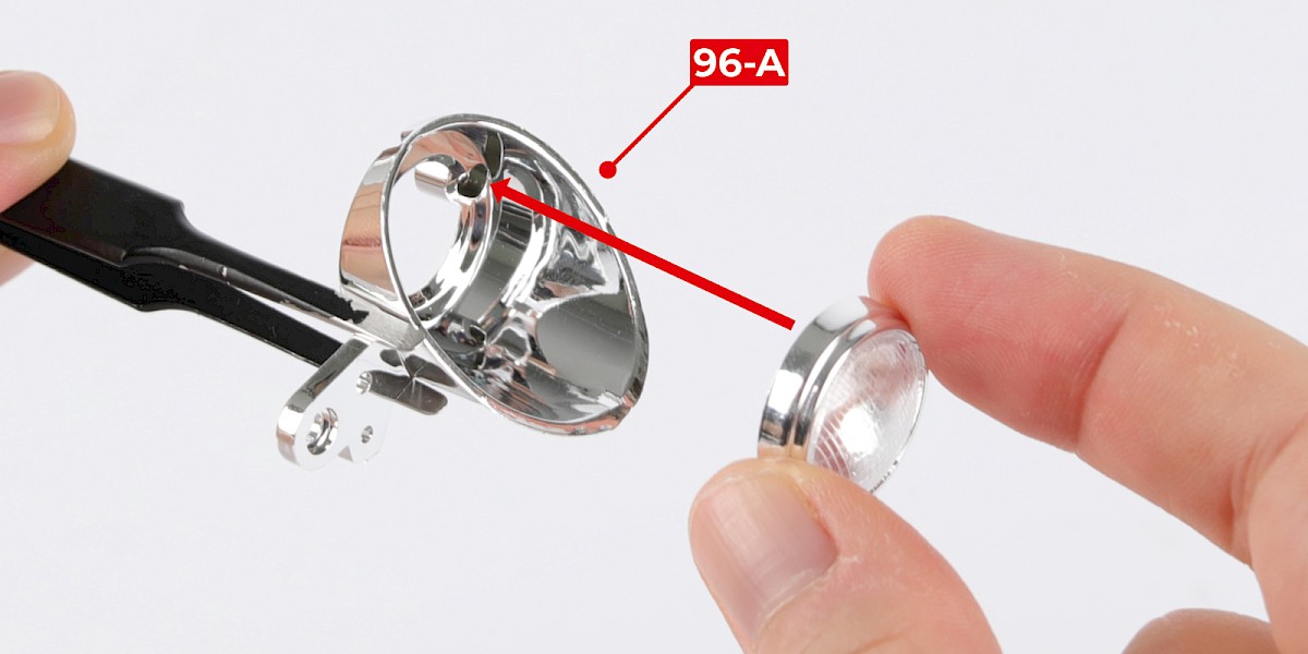
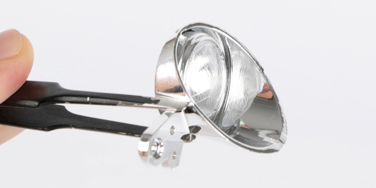
Step 3
Secure with 1x PS21.
Step 4
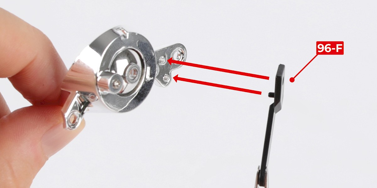
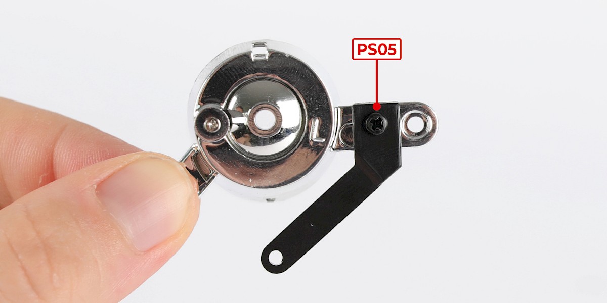
Fit the machine gun brace (96-F) to the assembly, then secure with 1x PS05.
Step 5
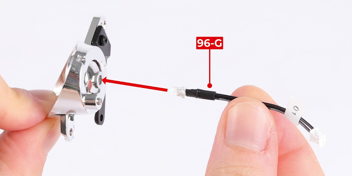
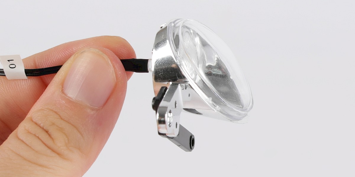
Fit the headlight LED (96-G) into the reflector.
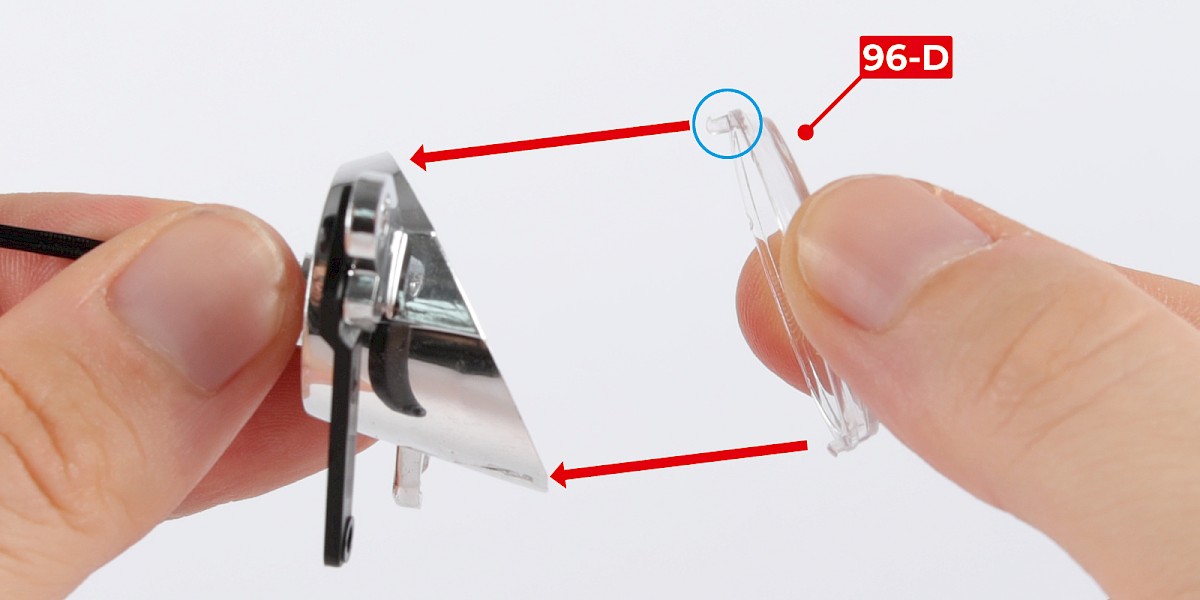
Step 6
Fit the headlight cover (96-D) onto the headlight housing.
Note that the tabs are different sizes. The large tab (circled) fits onto the top of the housing.
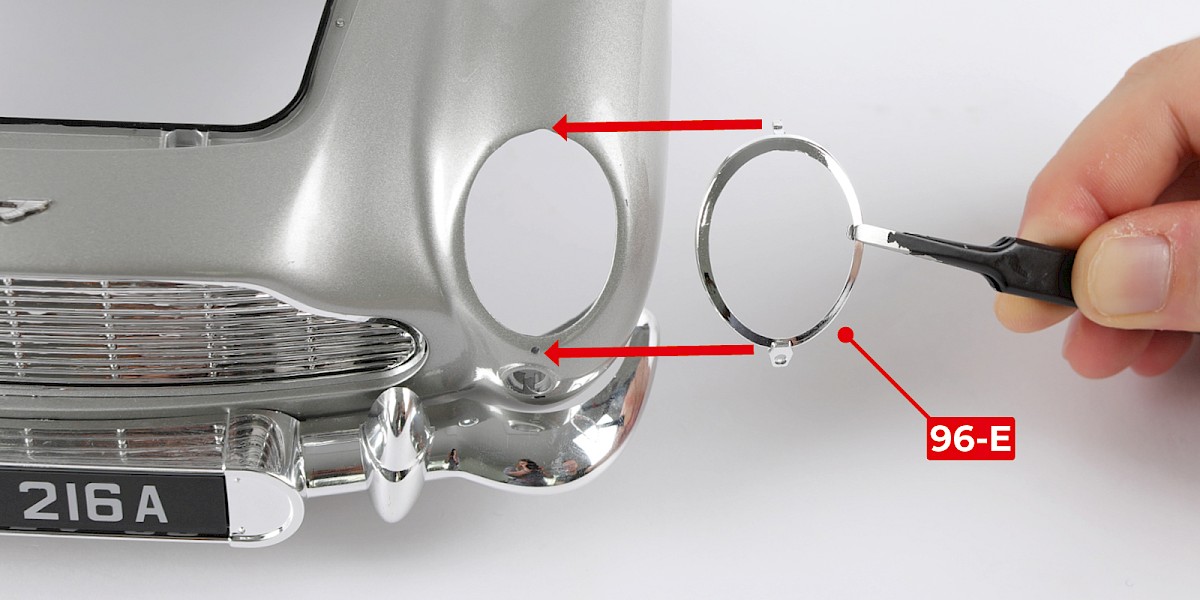
Step 7
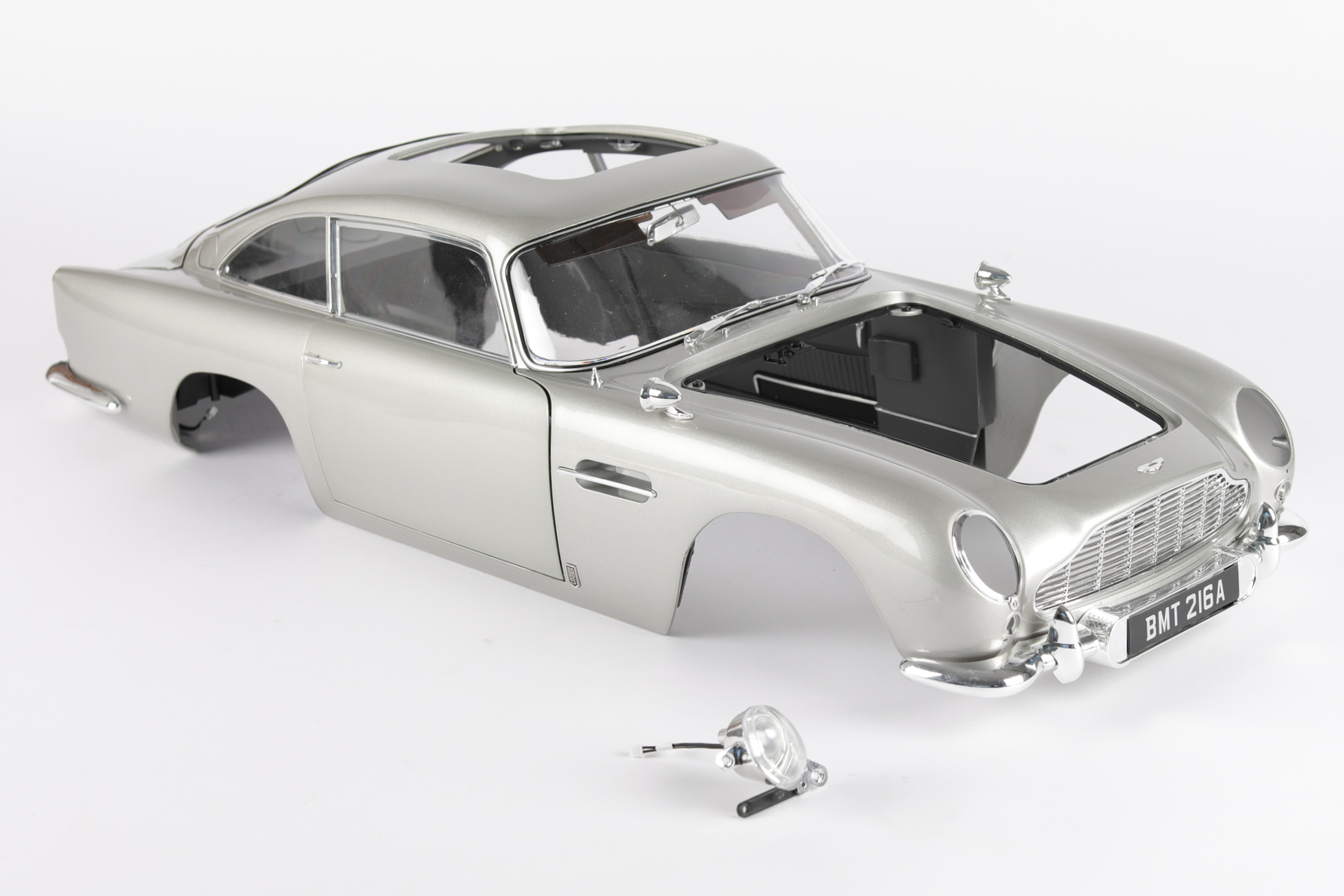
Fit the headlight bezel (96-E) to the main body (stage 95), then secure with 1x DS41.
STAGE COMPLETE
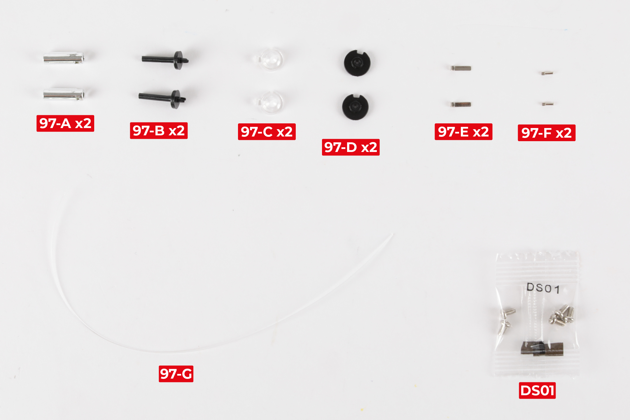
PARTS LIST
| 97-A Machine gun x2 | 97-E Hinge x2 |
| 97-B Guide rod x2 | 97-F Pin x2 |
| 97-C Indicator lens x2 | 97-G Nylon string |
| 97-D Indicator mount x2 | 5x DS01 screws |
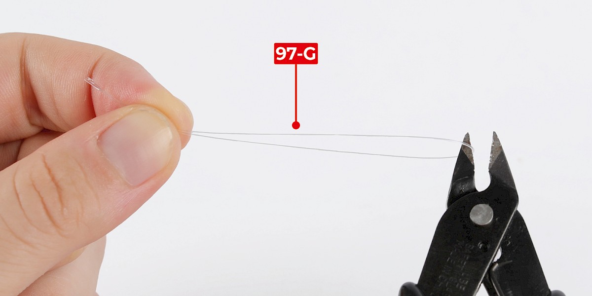
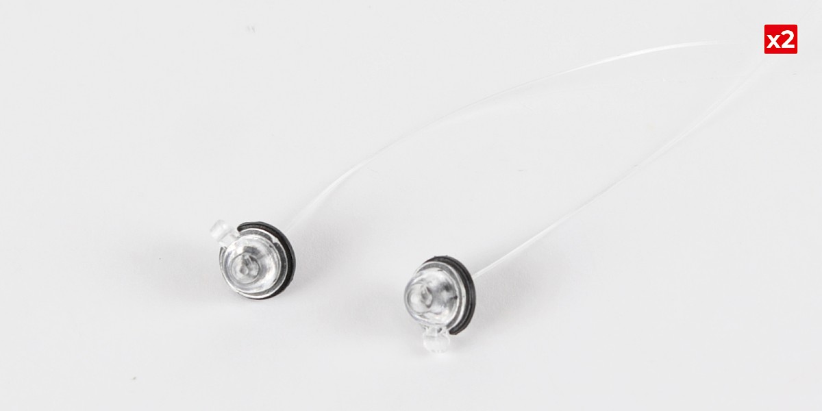
Step 1
Cut the nylon string (97-G) in half.
Step 2
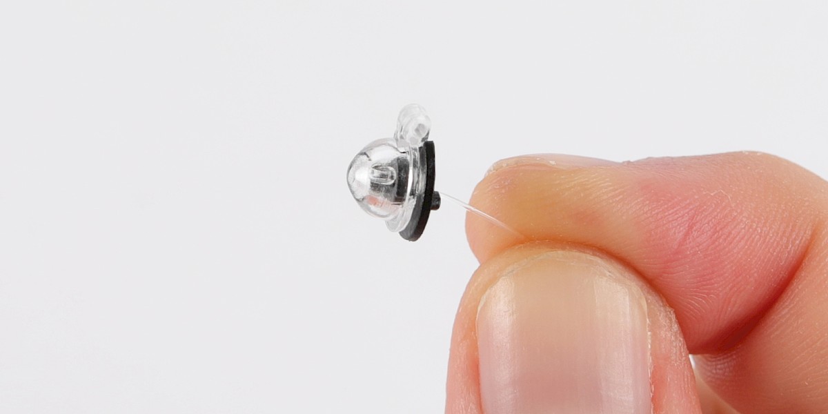
Thread the nylon string (97-G) through an indicator mount (97-D), then tie a knot at the end of the string.
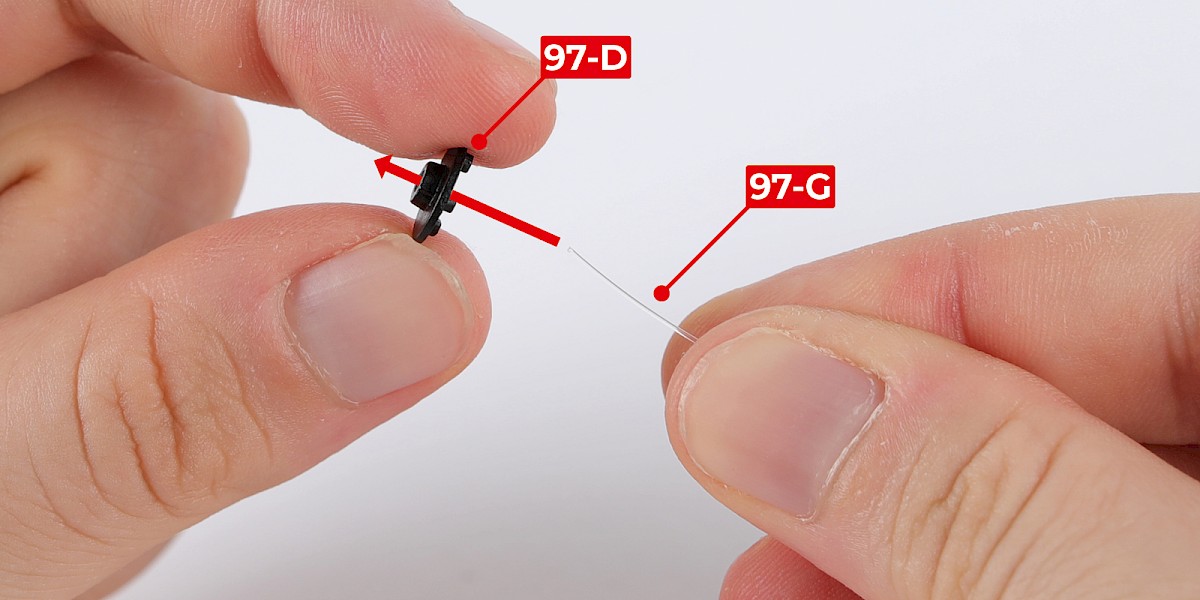
Step 3
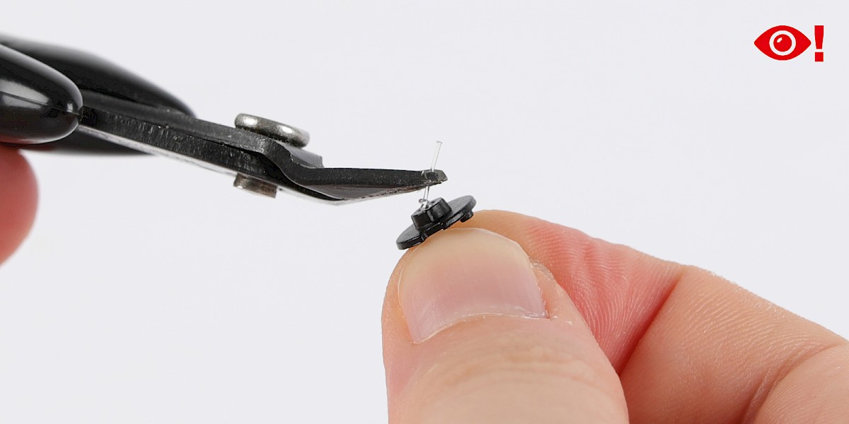
Cut off the excess string as shown, taking care not to cut too close to the knot.
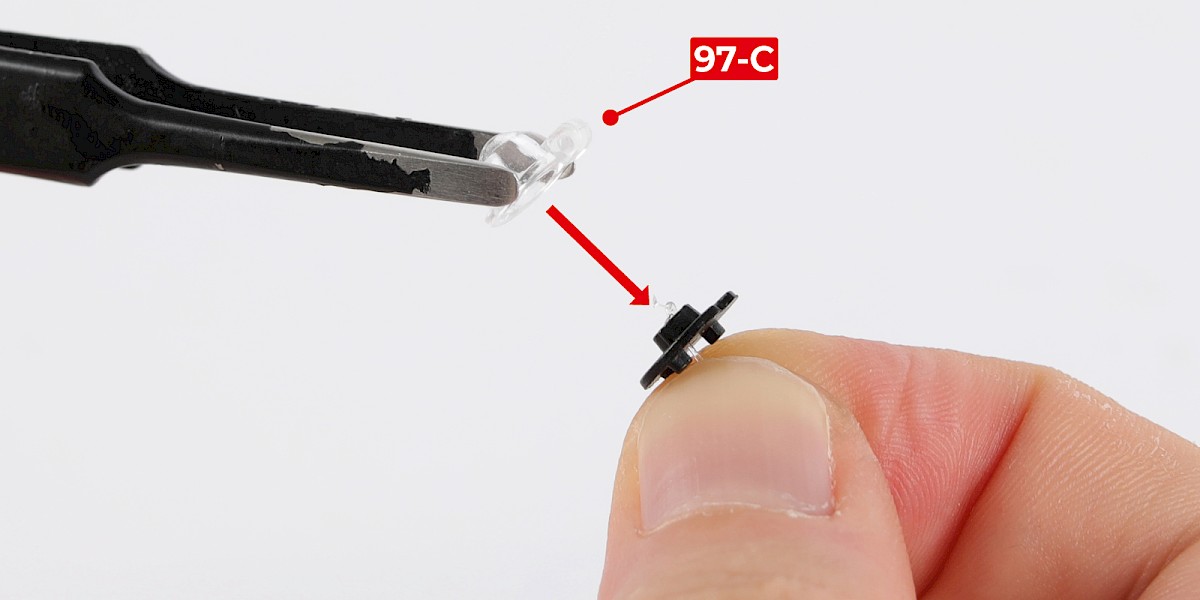
Step 4
Fit an indicator lens (97-C) onto the indicator mount.
Step 5
Repeat steps 2–4 to assemble a second indicator.
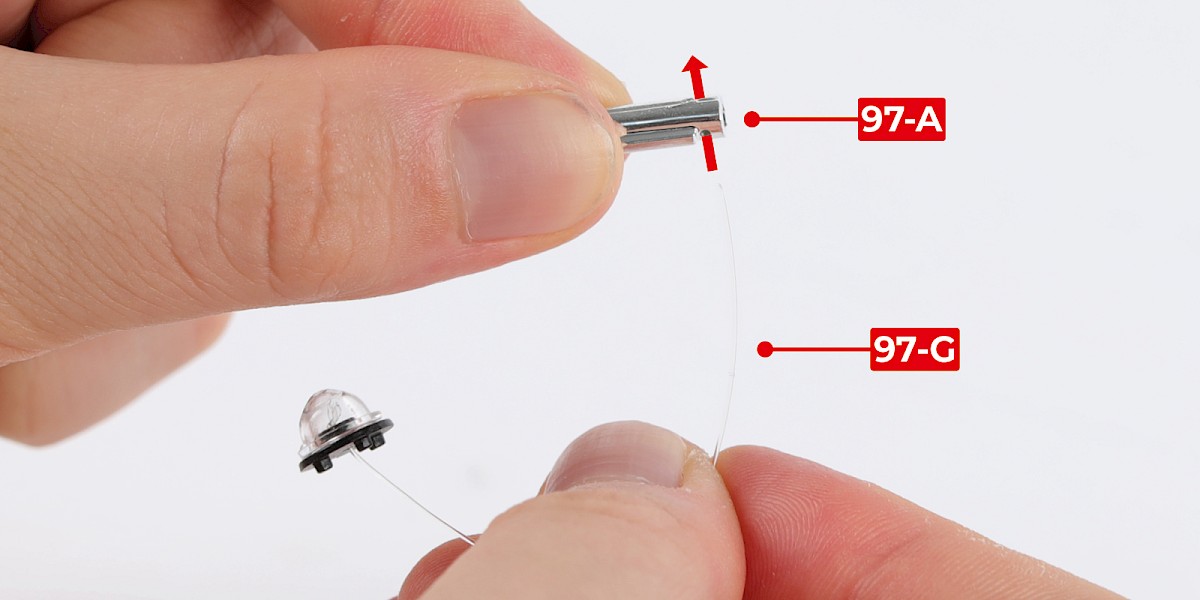
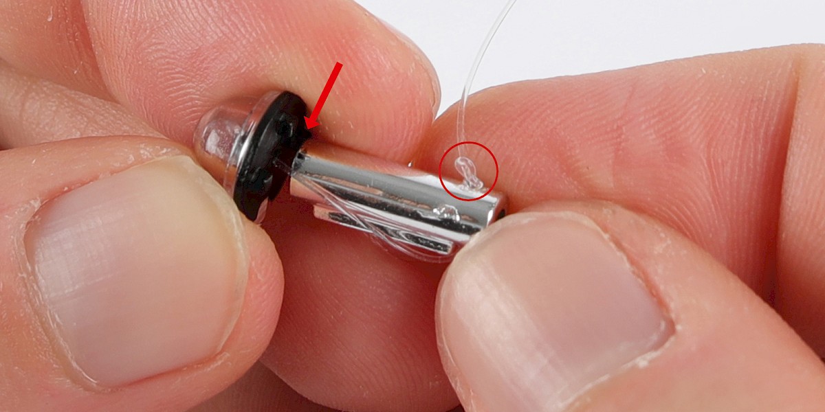
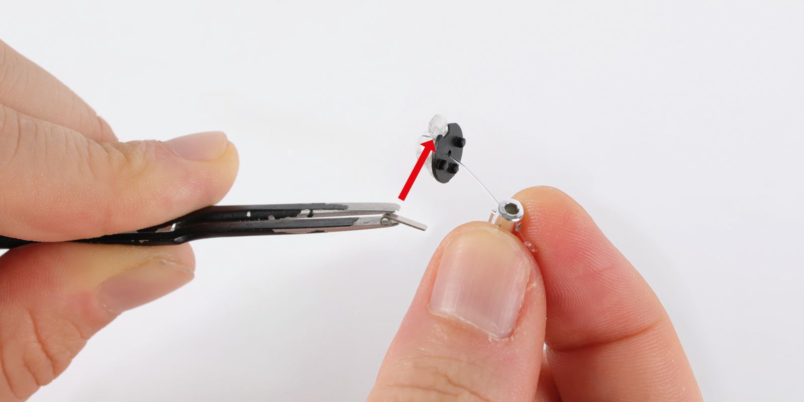
Step 6
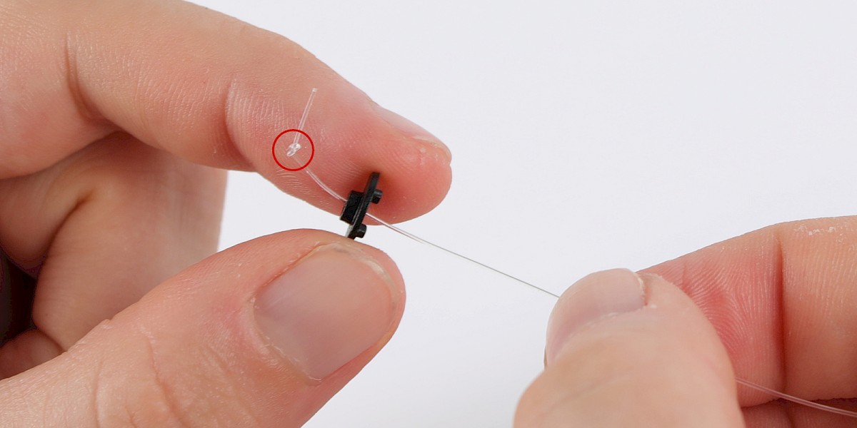
Thread the end of the nylon string through the machine gun (97-A).
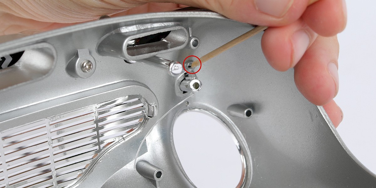
Continue to thread the string through until the indicator mount reaches the machine gun, then tie a knot in the string (circled). Repeat this step to assemble the second indicator.
Step 7
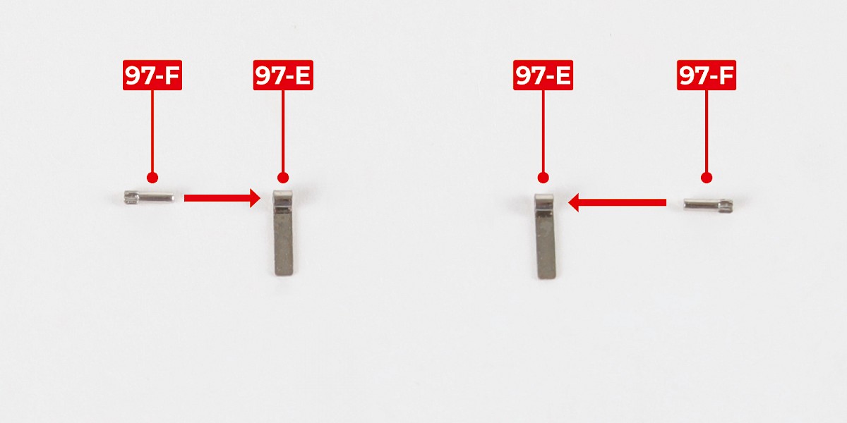
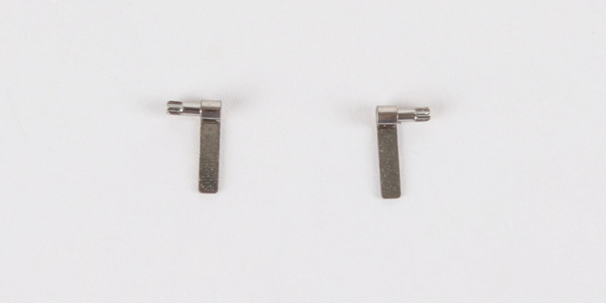
Fit the pins (97-F) into the hinges (97-E) as shown.
Step 8
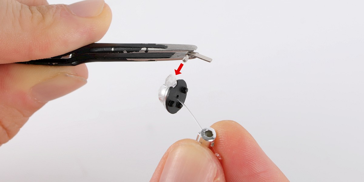
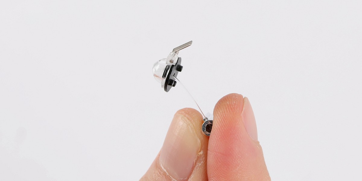
Fit the other end of the pin into the indicator lens as shown.
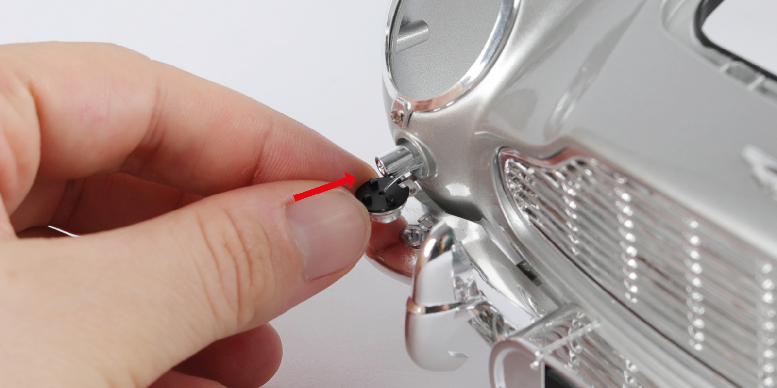
Step 9
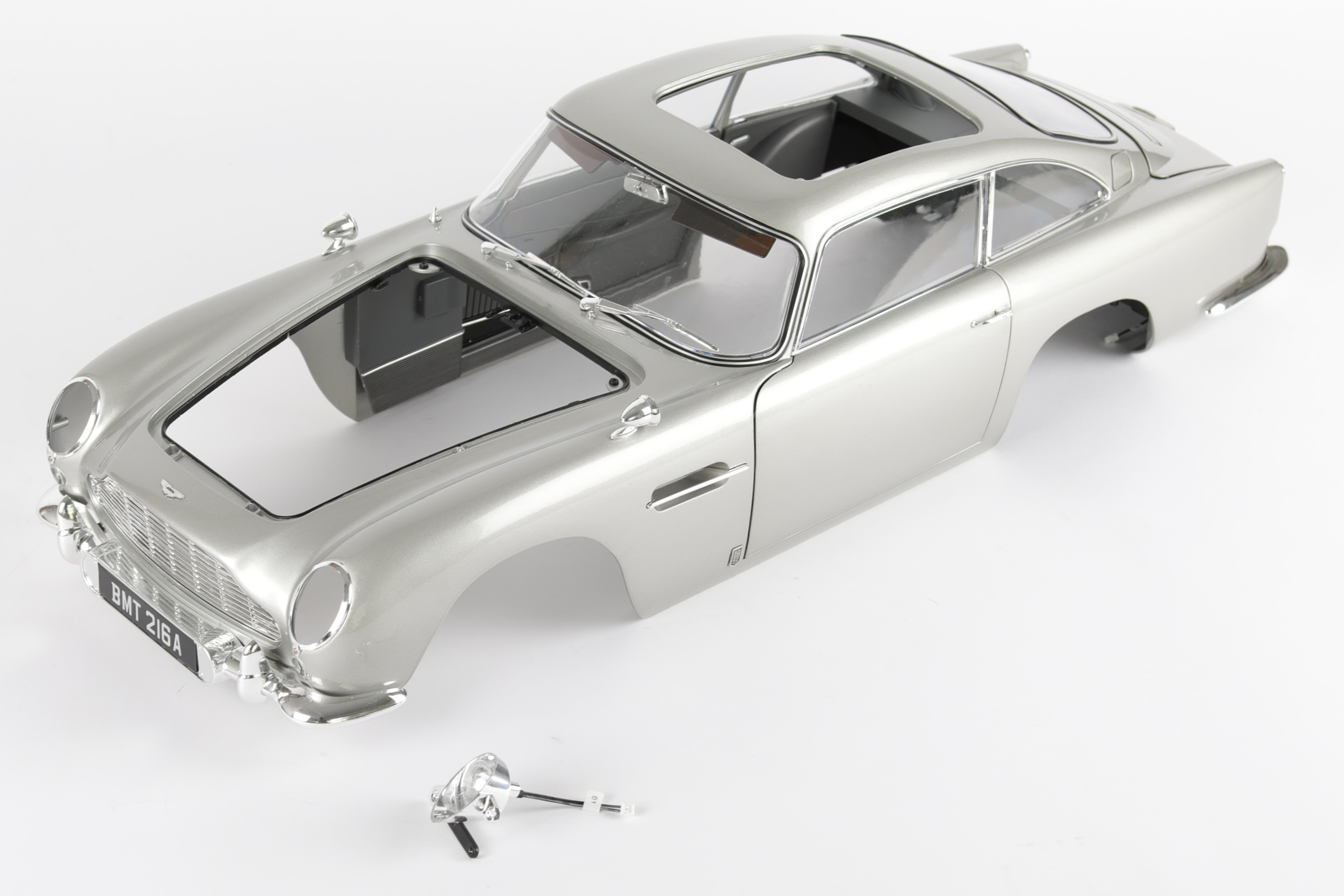
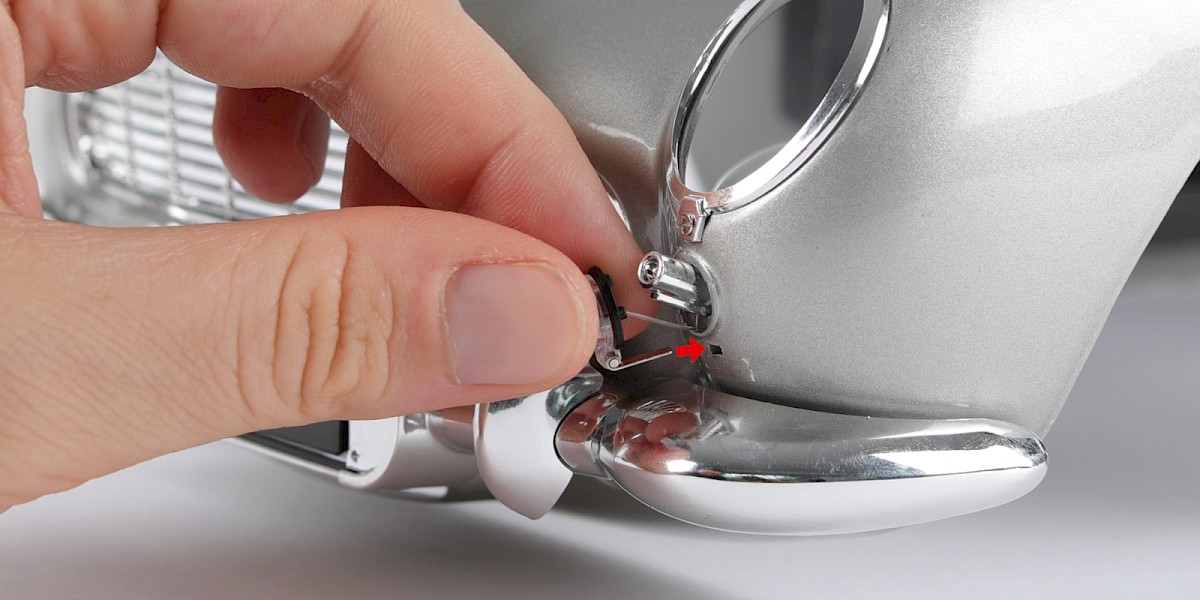
Fit the machine gun into the main body (stage 96), then fit the hinge into the small hole as shown.
Step 10
Push the indicator into the main body. When you are happy with the fit, glue the hinge in place. Be careful not to glue the machine gun or the lens.
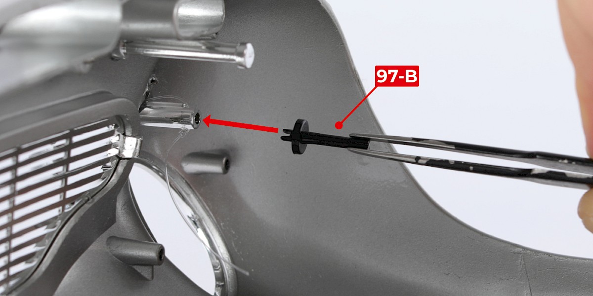
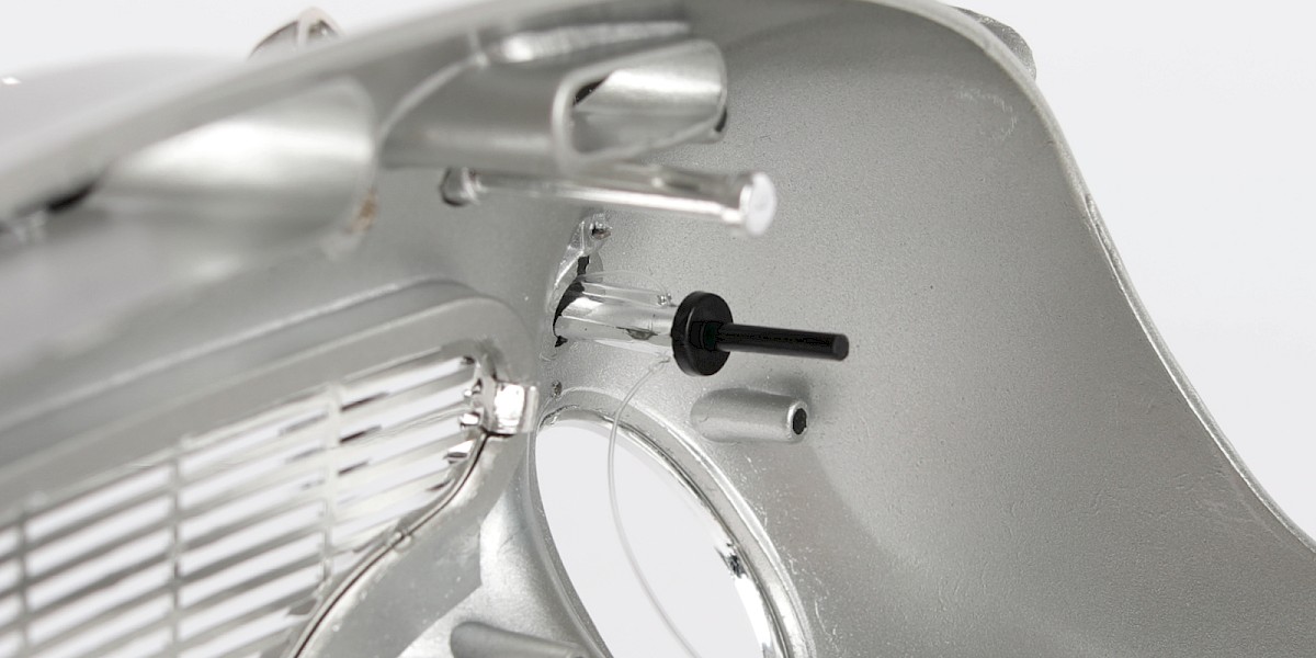
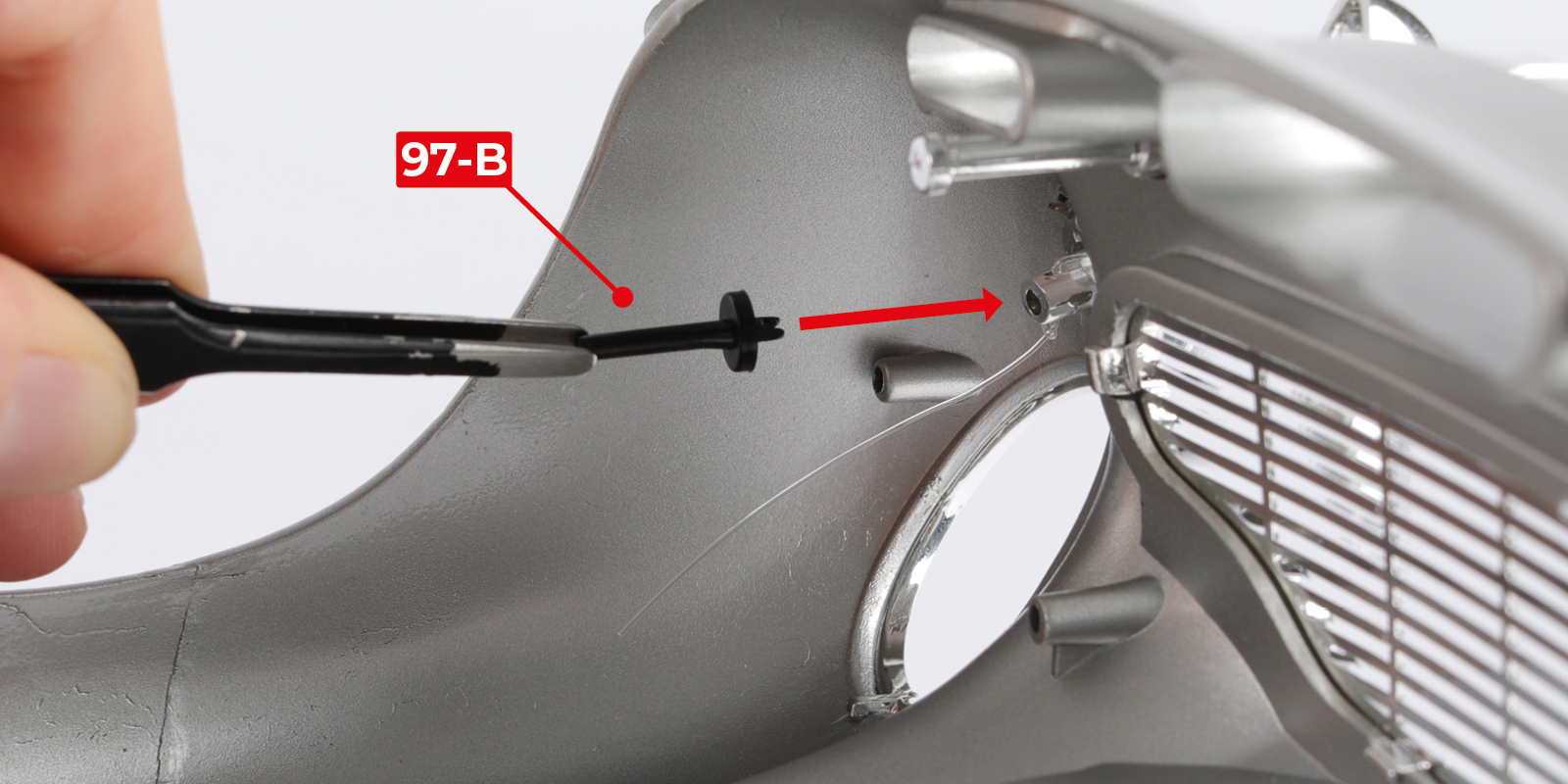
Step 11
Glue 97-B to the machine gun.
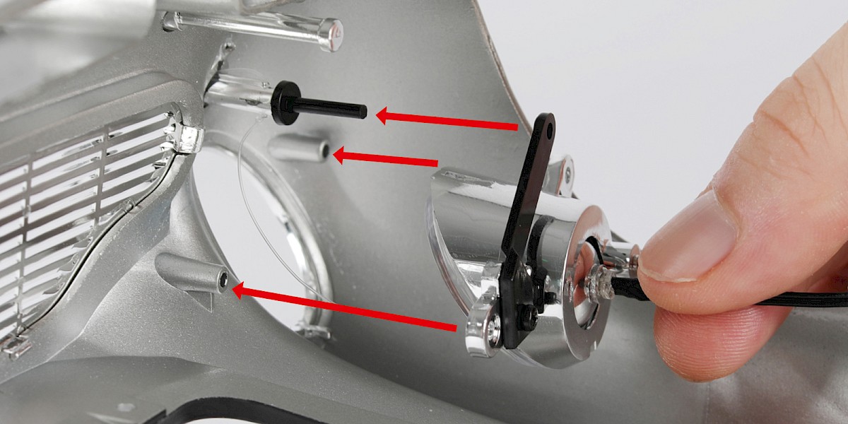
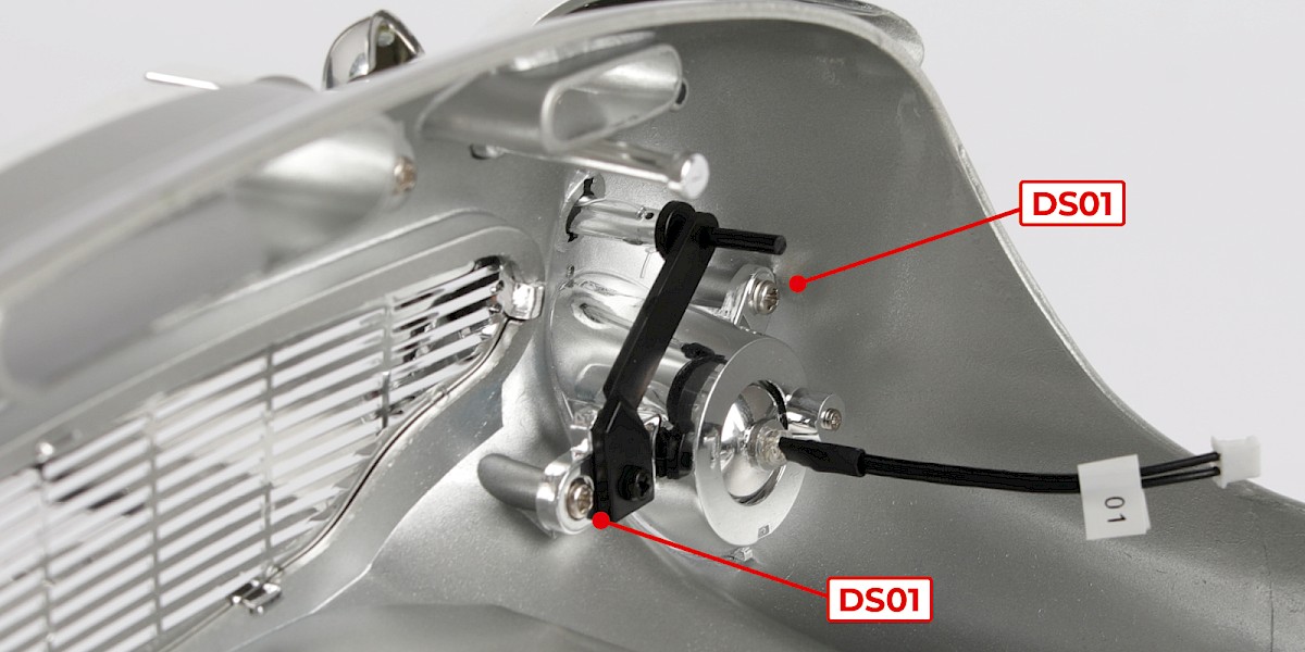
Step 12
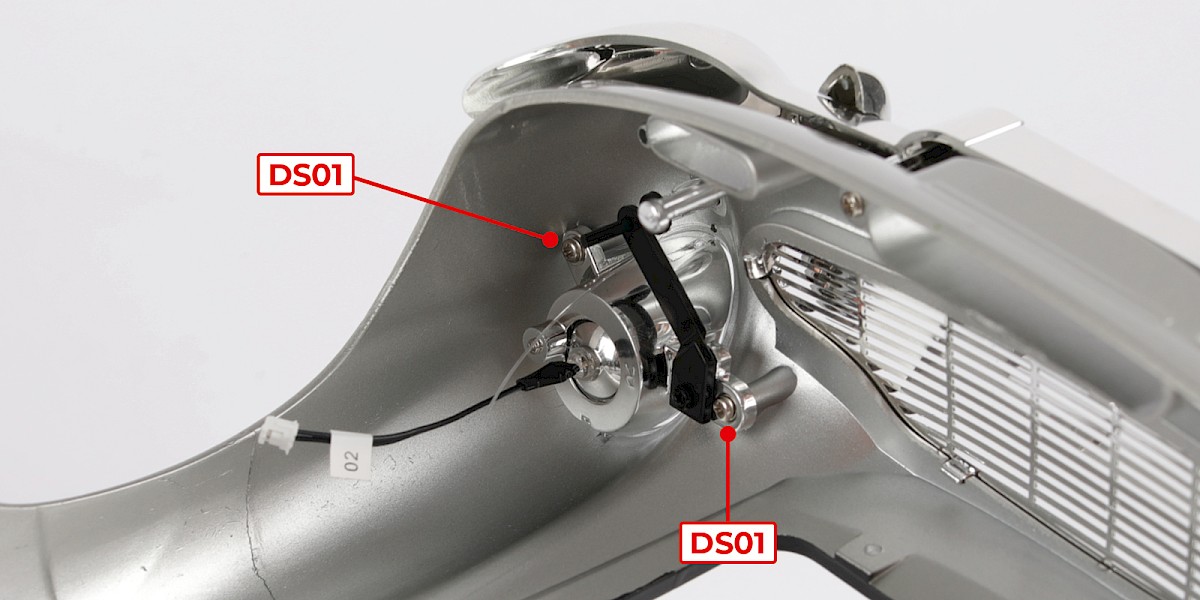
Fit the left headlight (stage 96) to the assembly then secure with 2x DS01.
Step 13
Repeat steps 8–11 to fit the right indicator and machine gun.
Step 14
Fit the right headlight (stage 95) to the assembly, then secure with 2x DS01.
Step 15
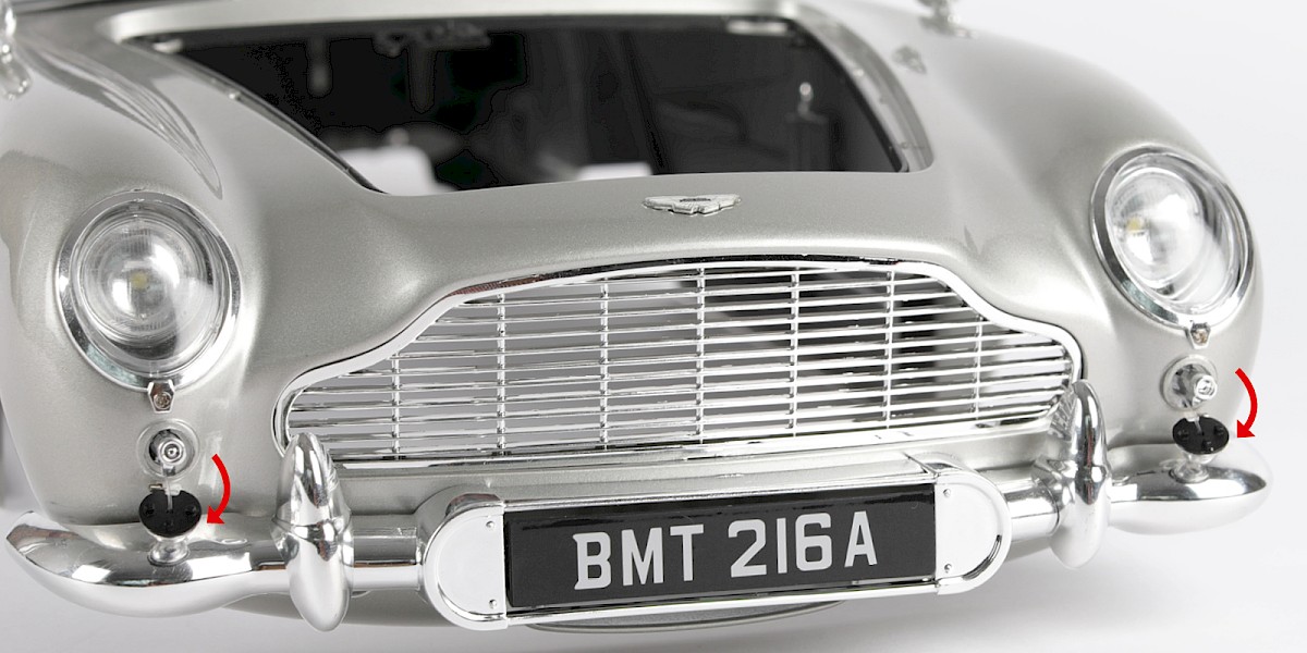
Pulling the indicator lights down will deploy the machine guns.
Step 16
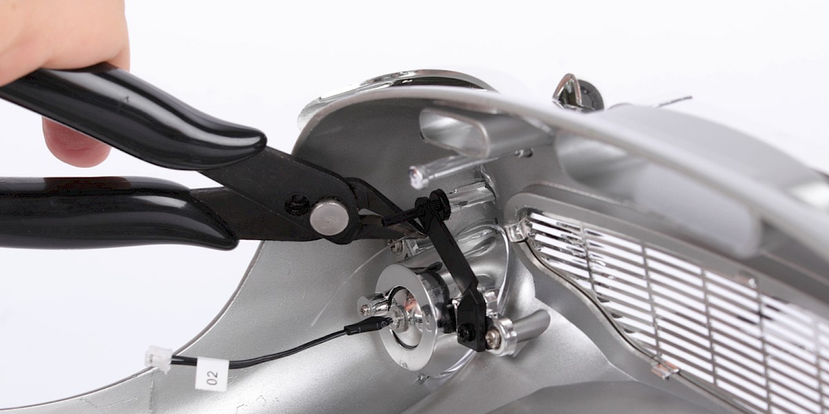
Cut off the excess nylon string from the machine guns.
STAGE COMPLETE
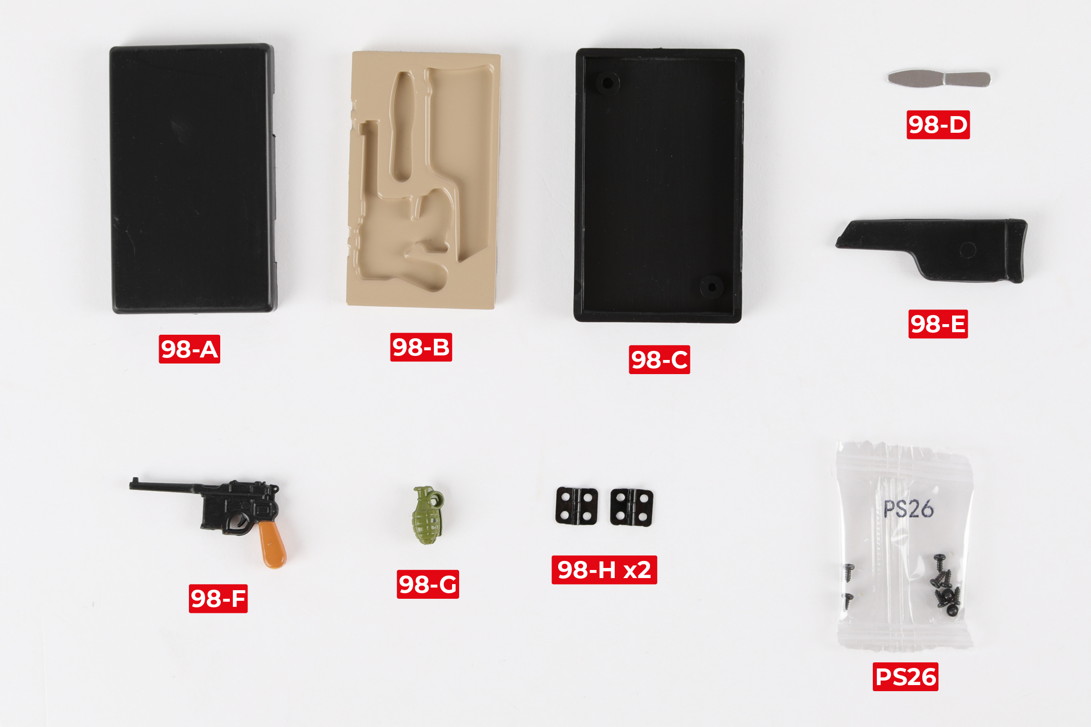
PARTS LIST
| 98-A Lid | 98-F Pistol |
| 98-B Tray | 98-G Hand grenade |
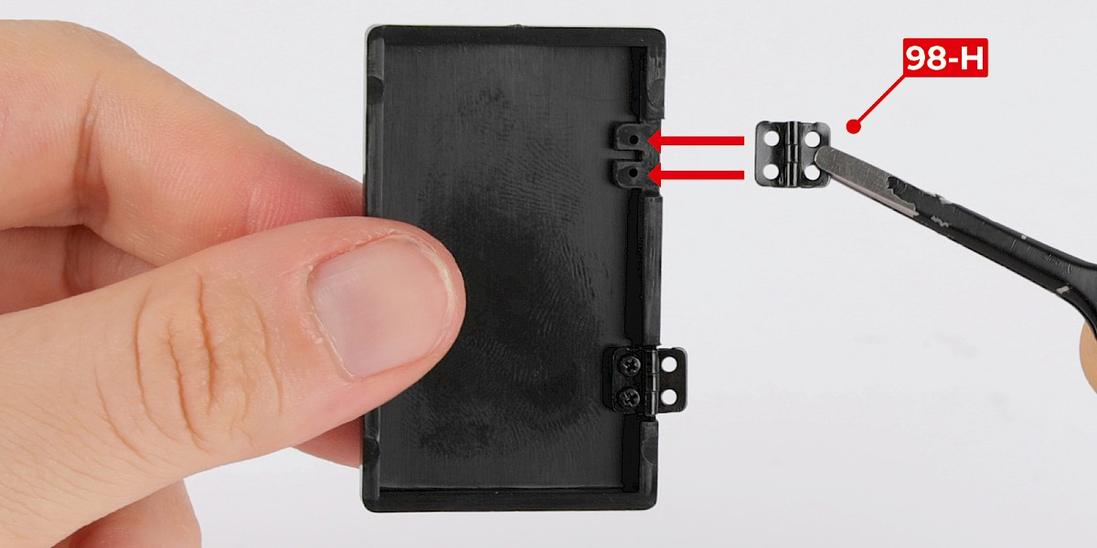
| 98-C Base | 98-H Hinge x2 |
| 98-D Throwing knife | 9x PS26 screws |
| 98-E Survival rifle |
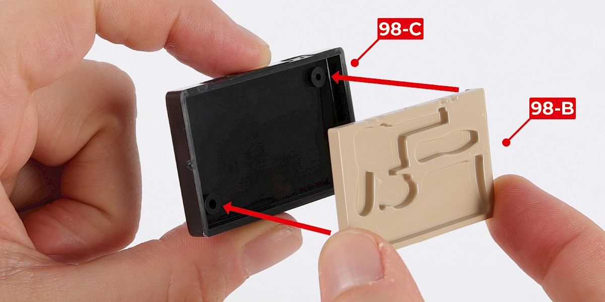
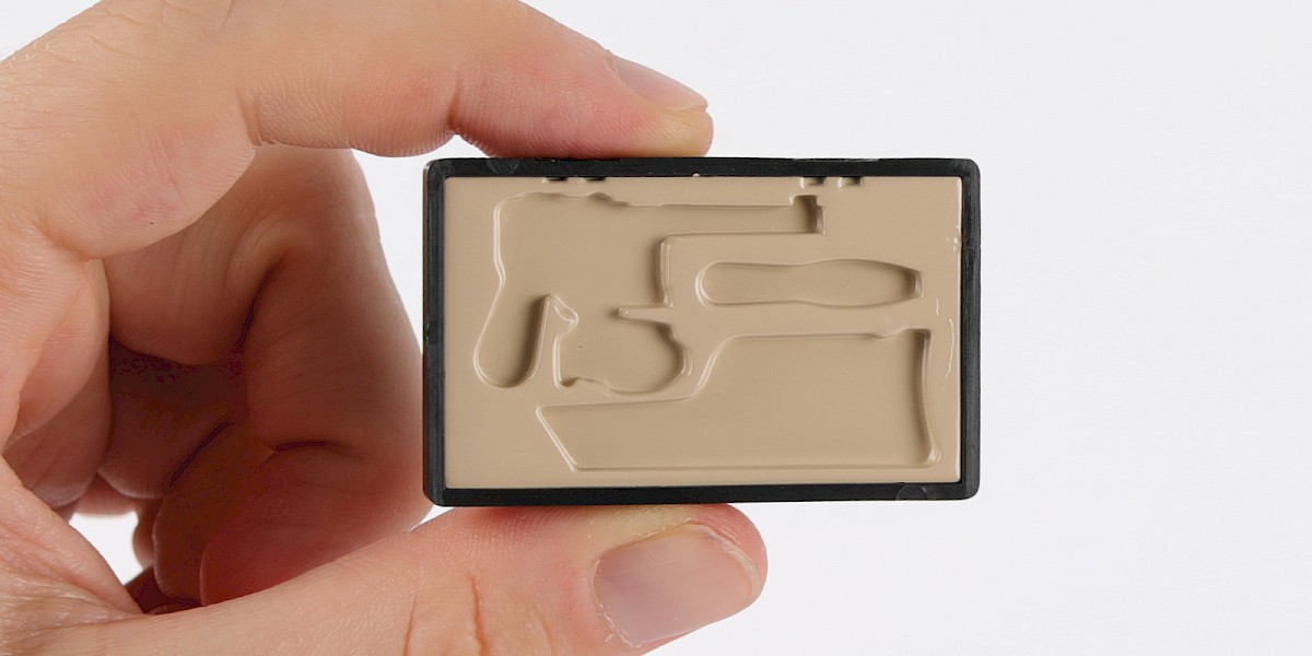
Step 1
Fit the tray (98-B) into the base (98-C).
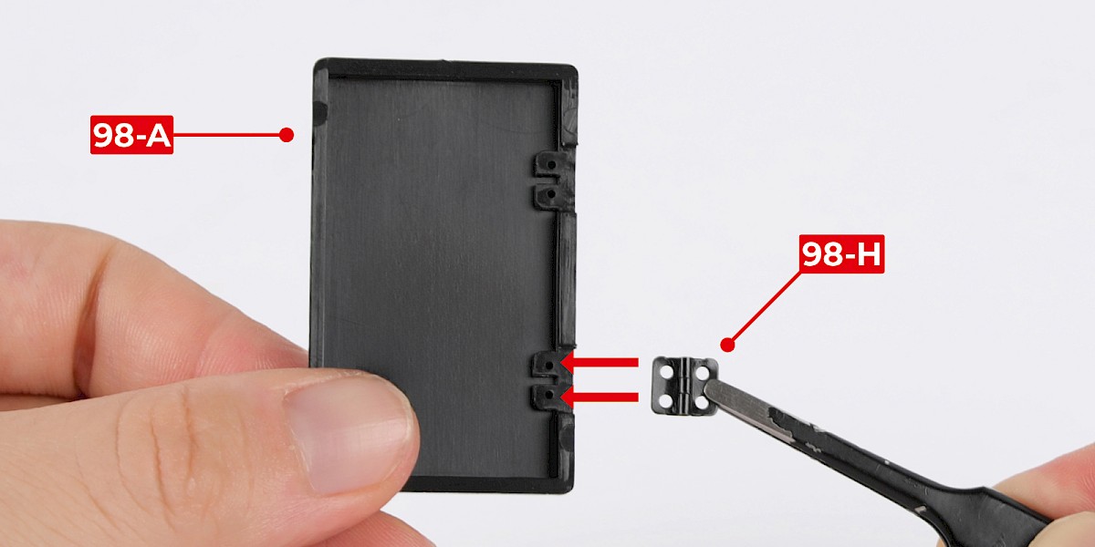
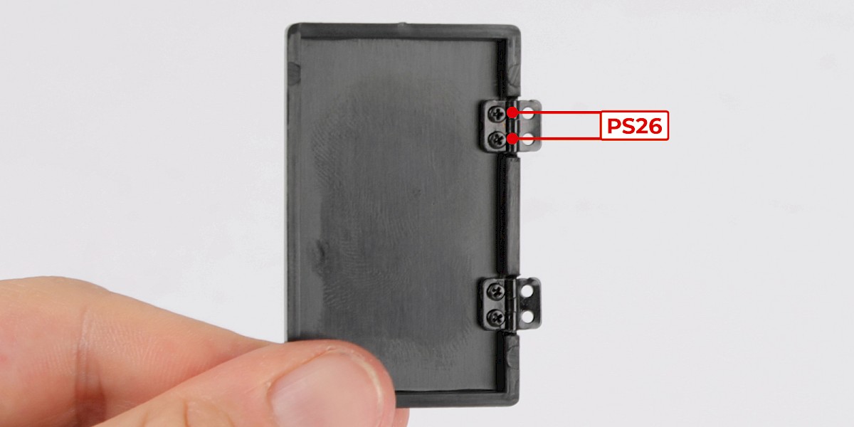
Step 2
Place a hinge (98-H) onto the lid (98-A), then secure with 2x PS26.

Step 3
Place the other hinge (98-H) onto the lid, then secure with 2x PS26.
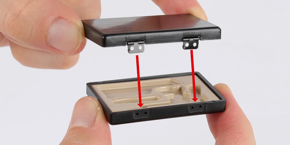
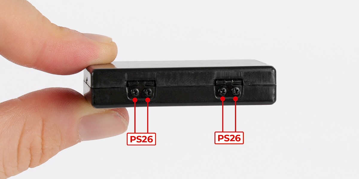
Step 4
Fit the hinges to the base, then secure with 4x PS26.
Step 5
Place the throwing knife (98-D), survival rifle (98-E), pistol (98-F) and hand grenade (98-G) into the tray.
STAGE COMPLETE
PARTS LIST
| 99-A Bonnet strut x2 | 99-F Circuit board |
| 99-B Battery compartment cover | 99-G Bonnet strut support x2 |
| 99-C Remote control housing | 7x DS29 screws |
| 99-D Remote control keypad | 8x PS32 screws |
| 99-E Remote control front |
Step 1
Fit the remote control front (99-E) onto the remote control keypad (99-D).
Step 2
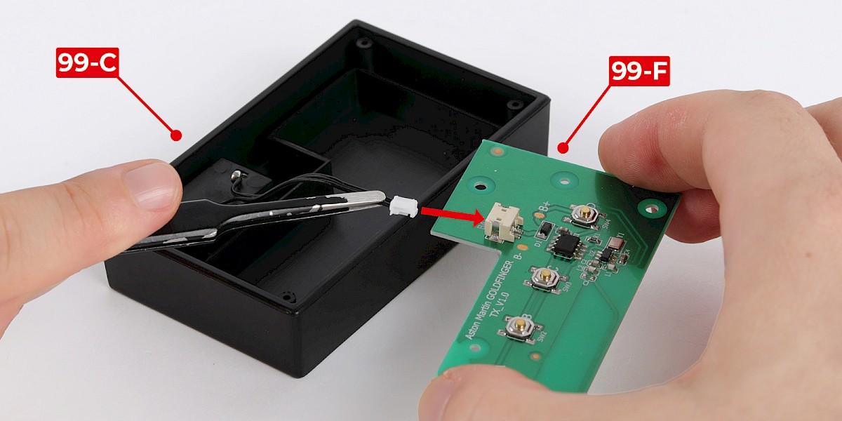
Plug the cable of the remote control housing (99-C) into the socket of the circuit board (99-F).
Step 3
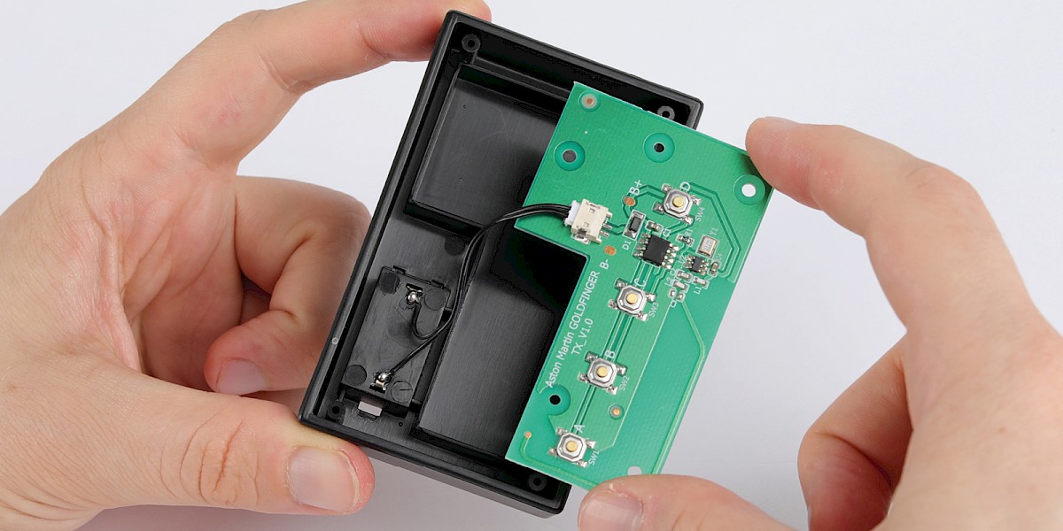
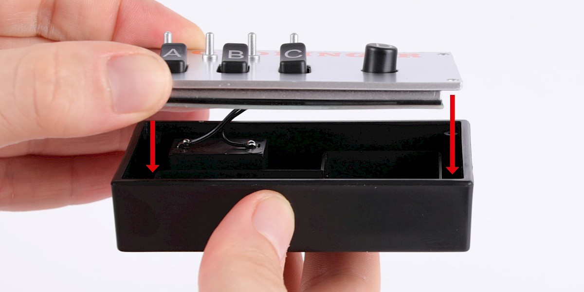
Fit the remote control keypad onto the circuit board, then secure with 3x PS32.
Step 4
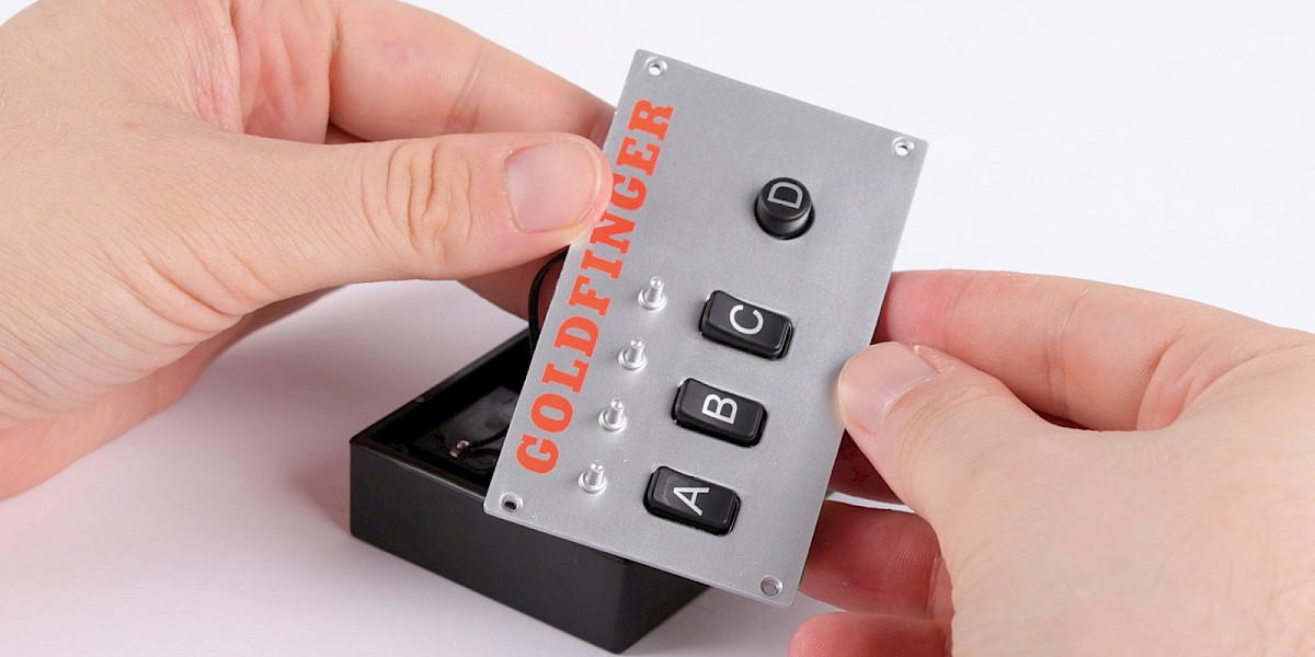
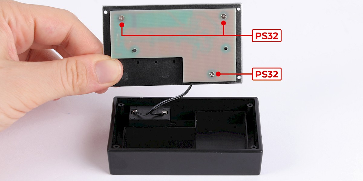
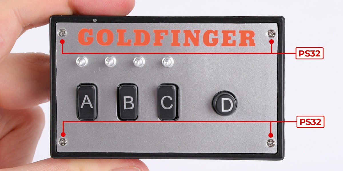
Place the remote control front onto the remote control housing, then secure with 4x PS32.
Step 5
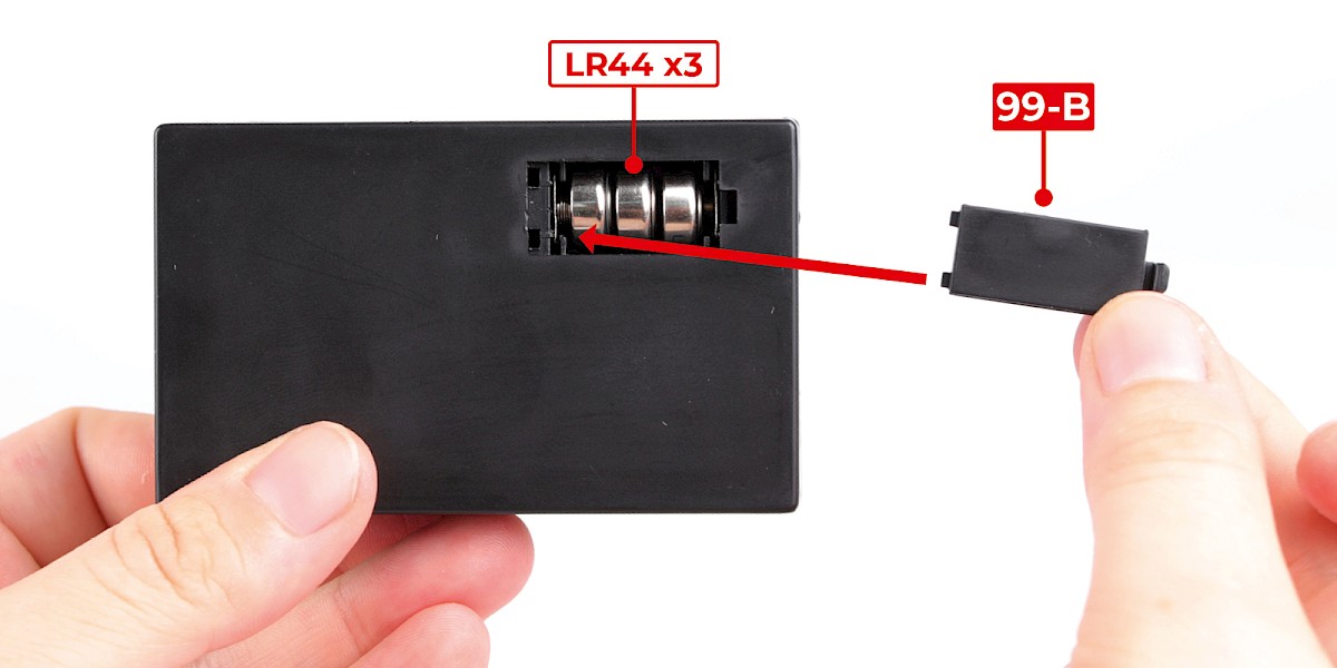
Insert 3x LR44 batteries into the remote control then fit the battery compartment cover (99-B).
Step 6
Fit a bonnet strut support (99-G) to the main body (stage 97), then secure with 2x DS29.
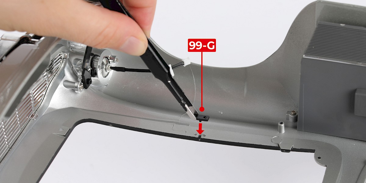
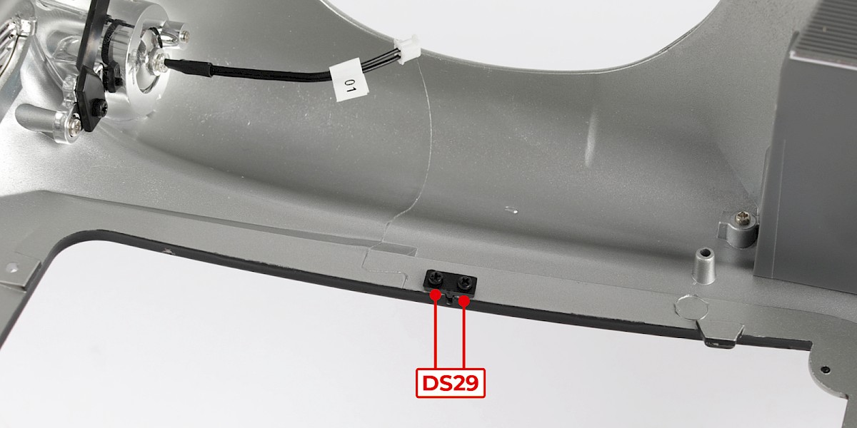
Step 7
Fit a bonnet strut support (99-G) to the other side, then secure with 2x DS29.

Step 8
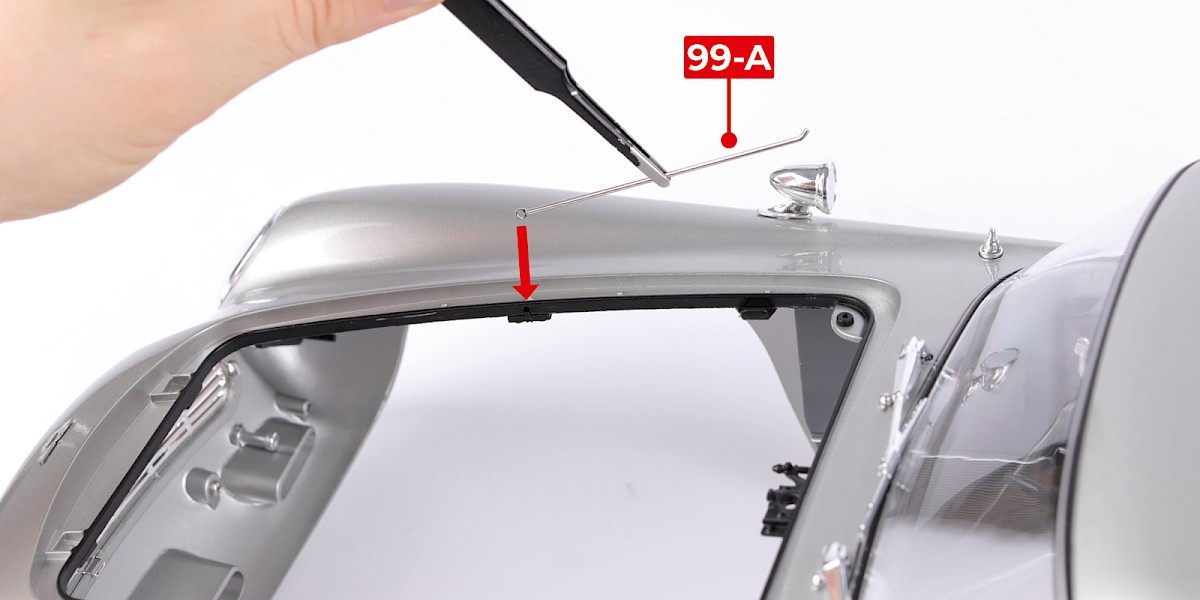
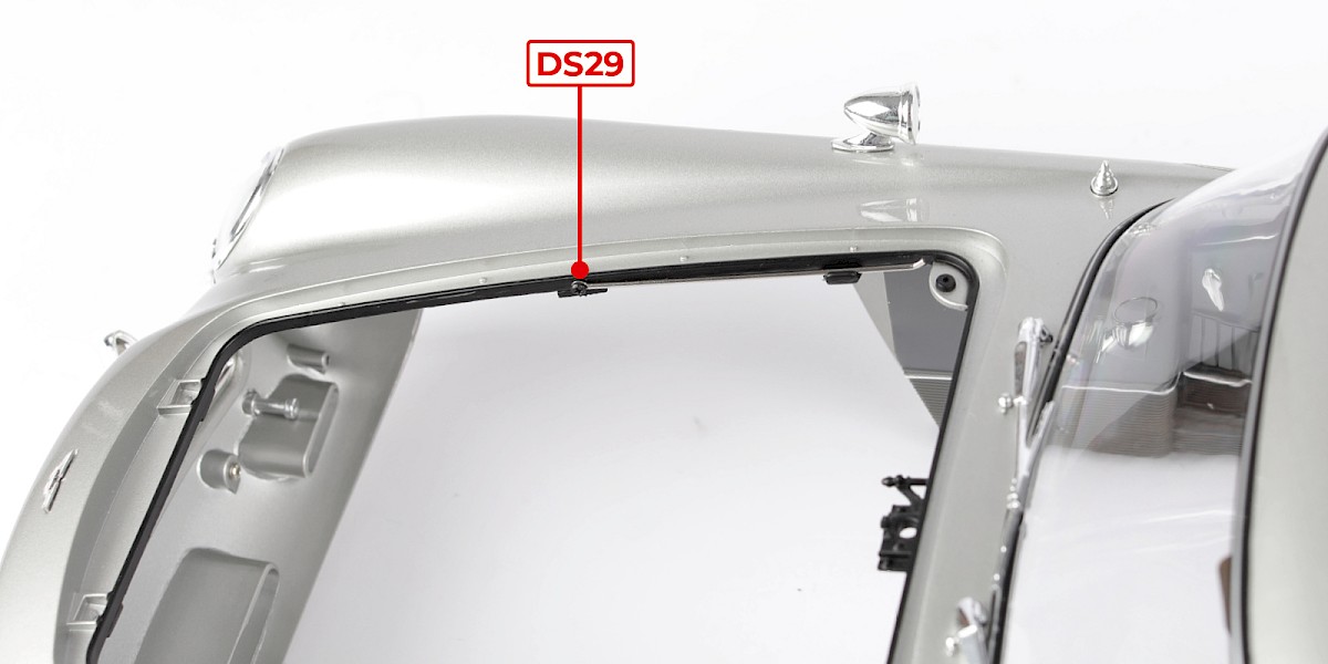
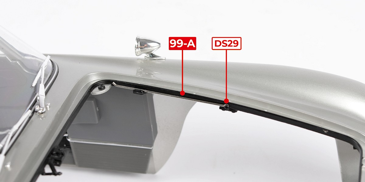
Fit a bonnet strut (99-A) to the support, then secure with 1x DS29.
Note that the tip of the bonnet strut should point upwards.
Step 9
Fit a bonnet strut (99-A) to the other support, then secure with 1x DS29.
STAGE COMPLETE
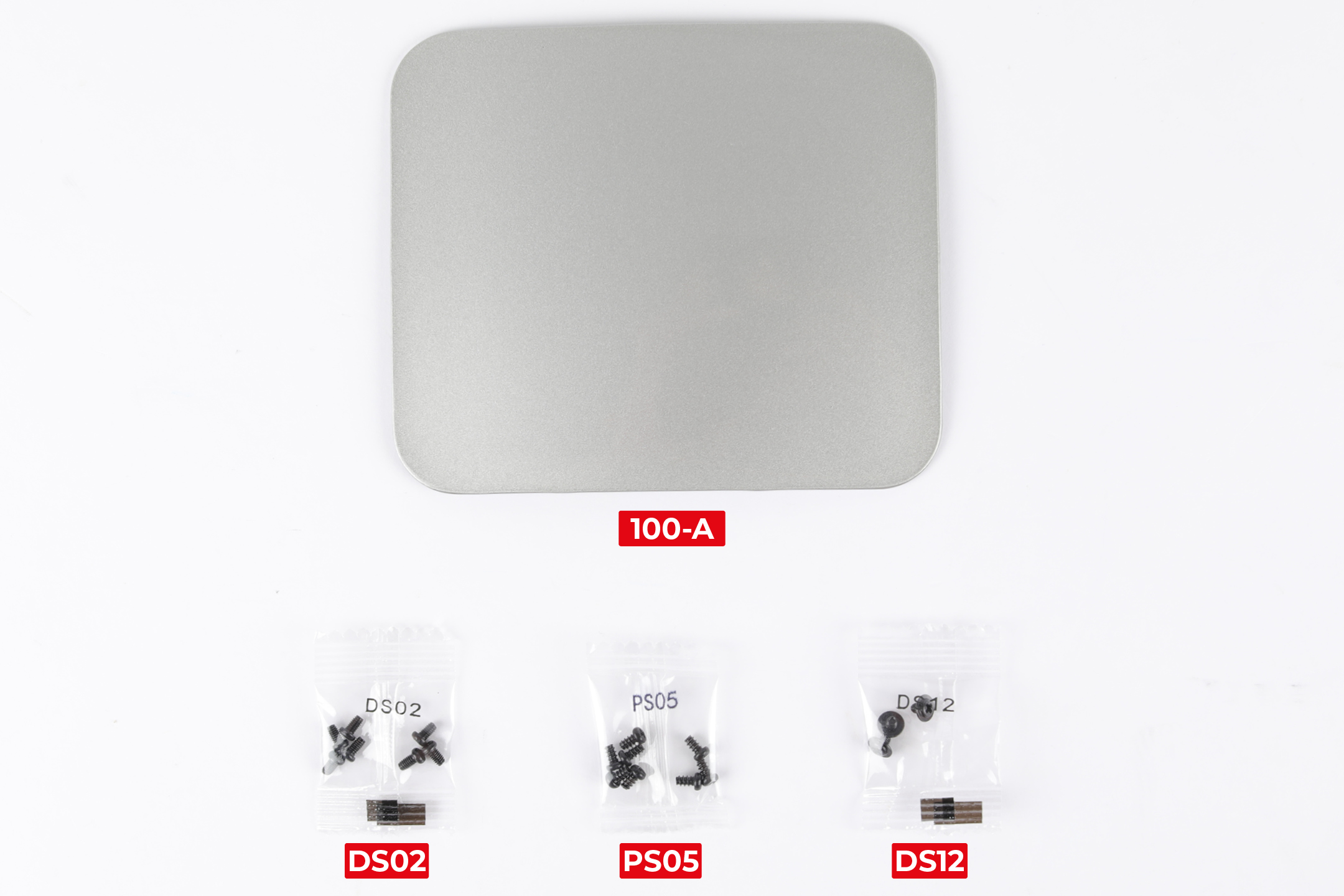
PARTS LIST
| 100-A Roof panel |
| 7x DS02 screws |
| 8x PS05 screws |
| 3x DS12 screws |
Step 1
Fit the bonnet (stage 001) to the main body.
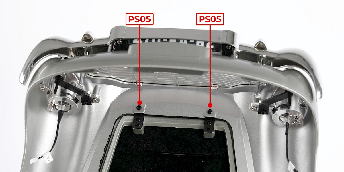
Step 2
Secure with 2x PS05.
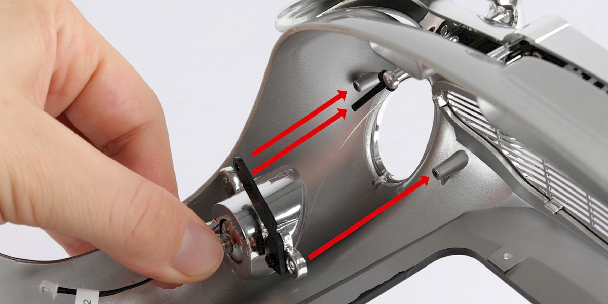
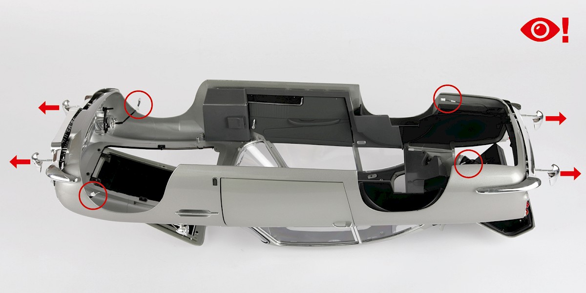
Step 3
Place the main body upside down on a soft surface. Pull the front and rear battering rams out from the bumpers (arrows). Keep the cables (circled) away to avoid trapping them during the next step.
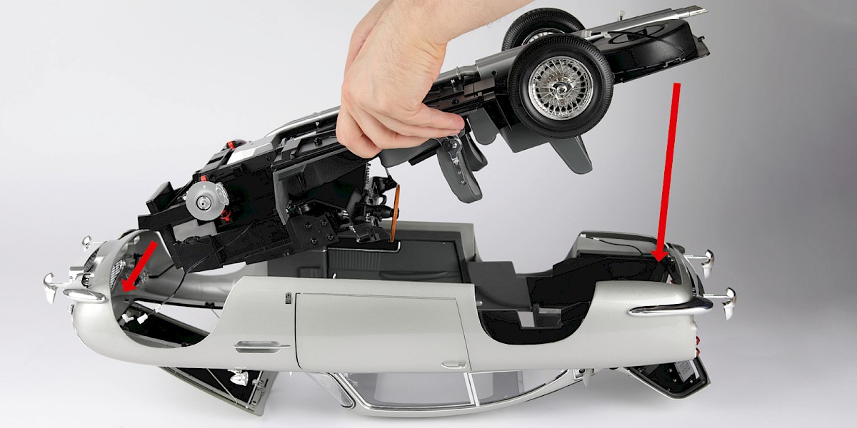
Step 4
Fit the chassis carefully into the main body, starting with the front.
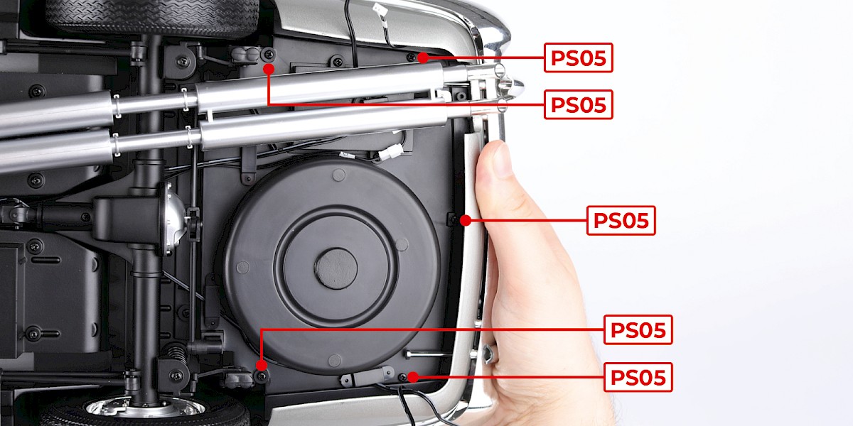
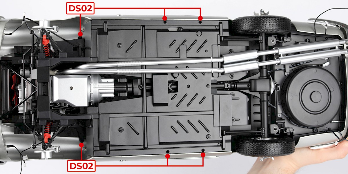
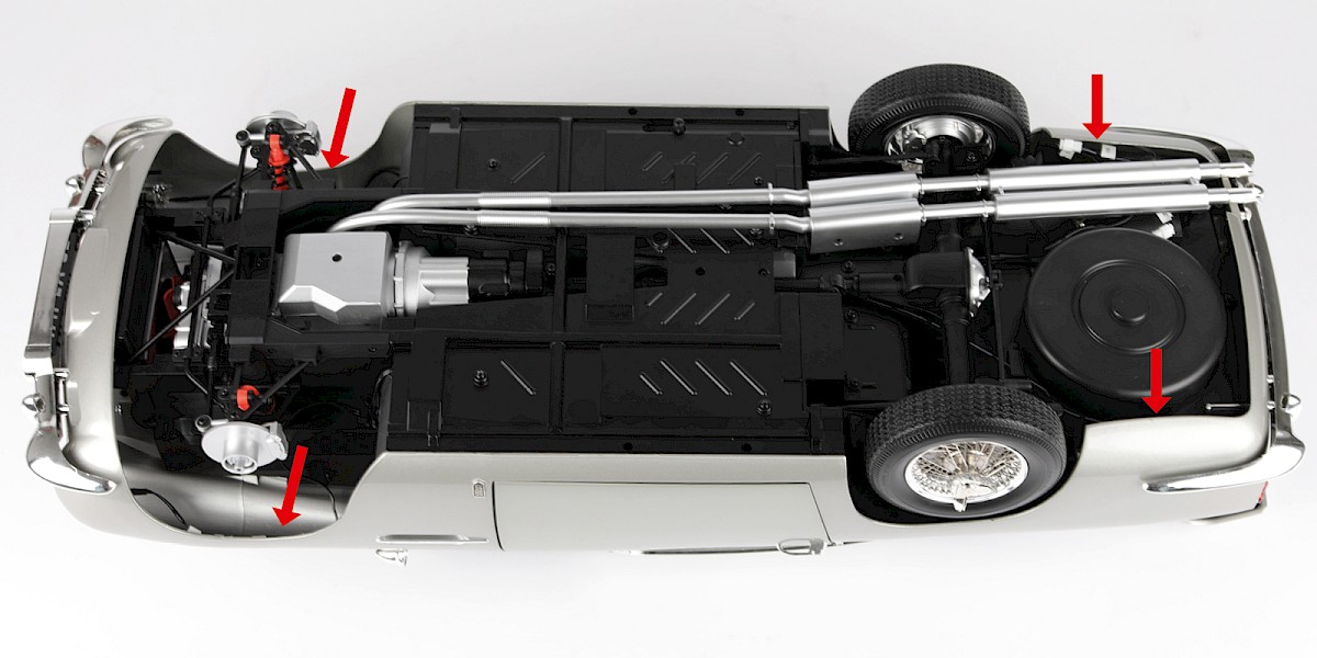
Step 5
Secure the rear section with 5x PS05, then secure the middle section with 6x DS02.
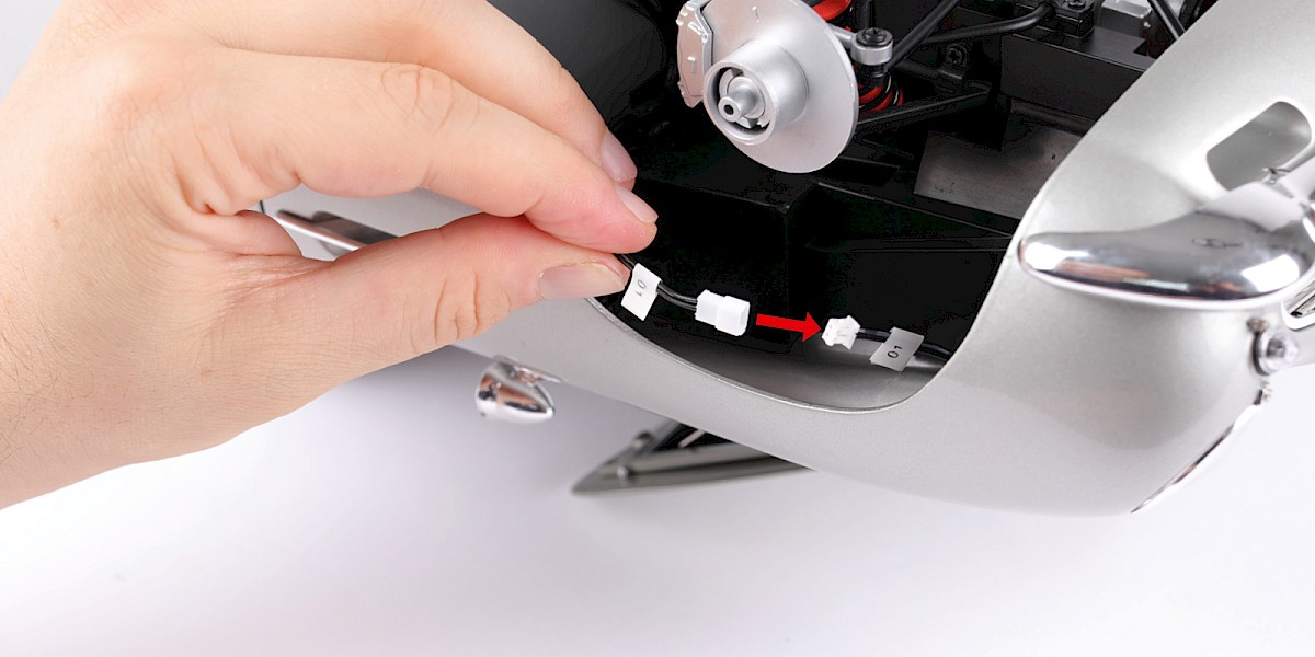
Step 6
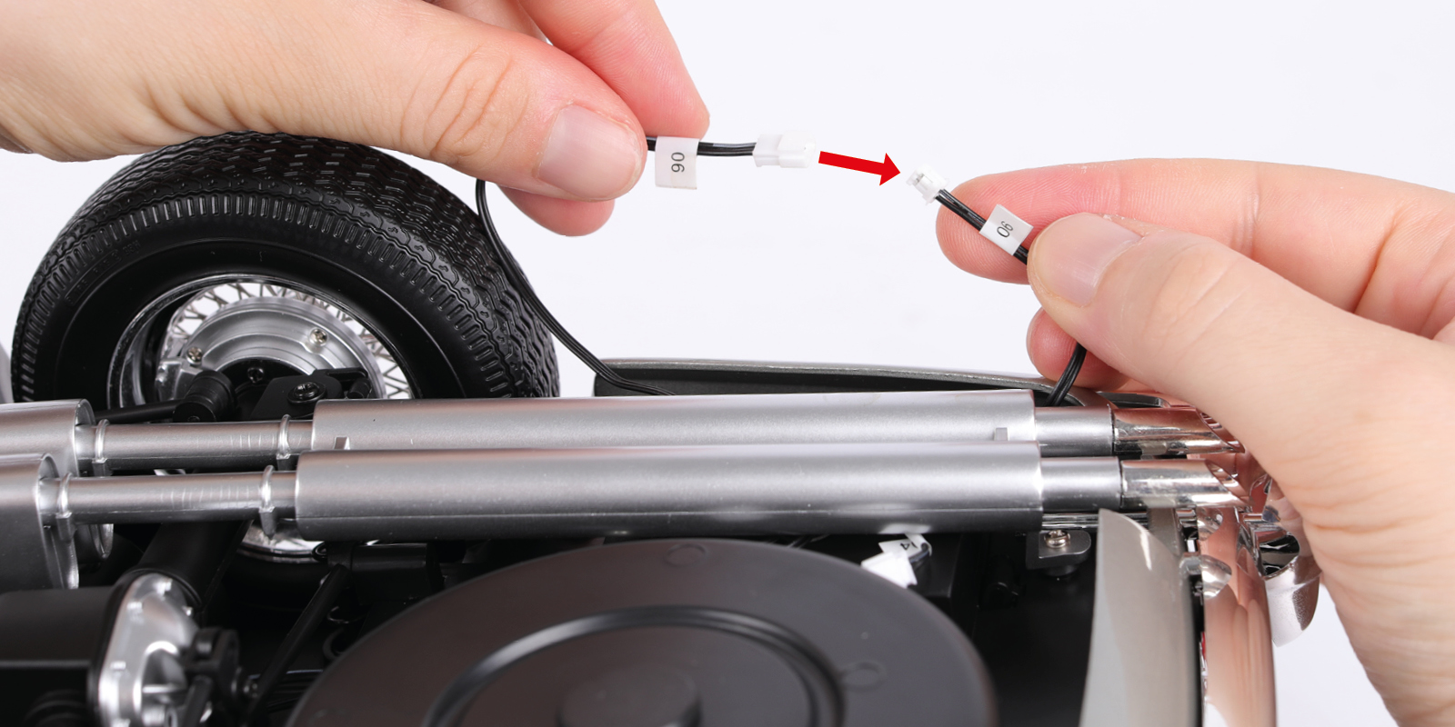
Connect the cables 01 together.
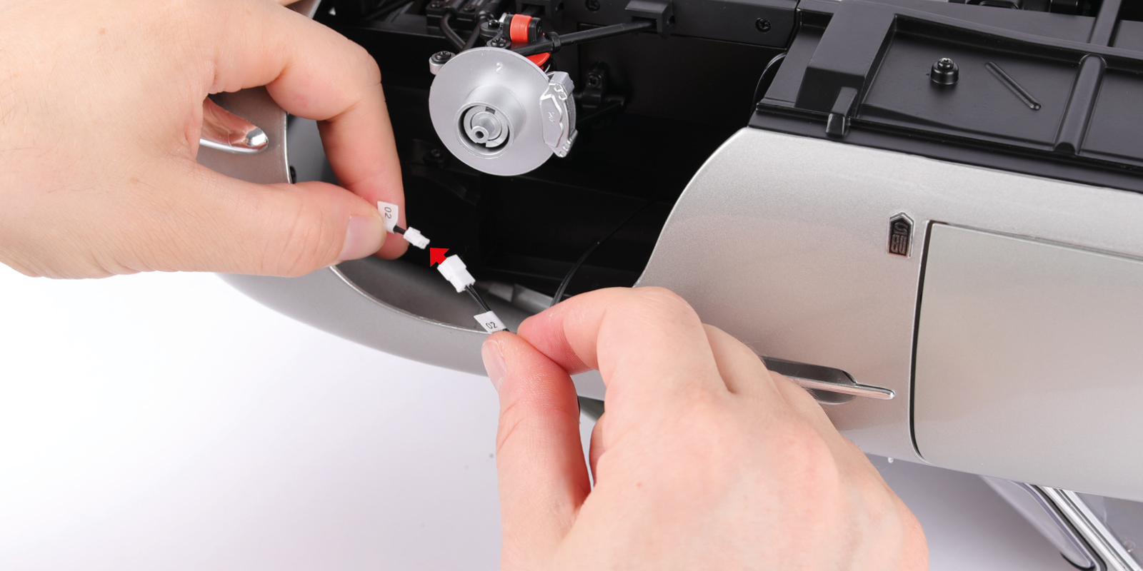
Step 7
Connect the cables 02, 06 and 07 together.
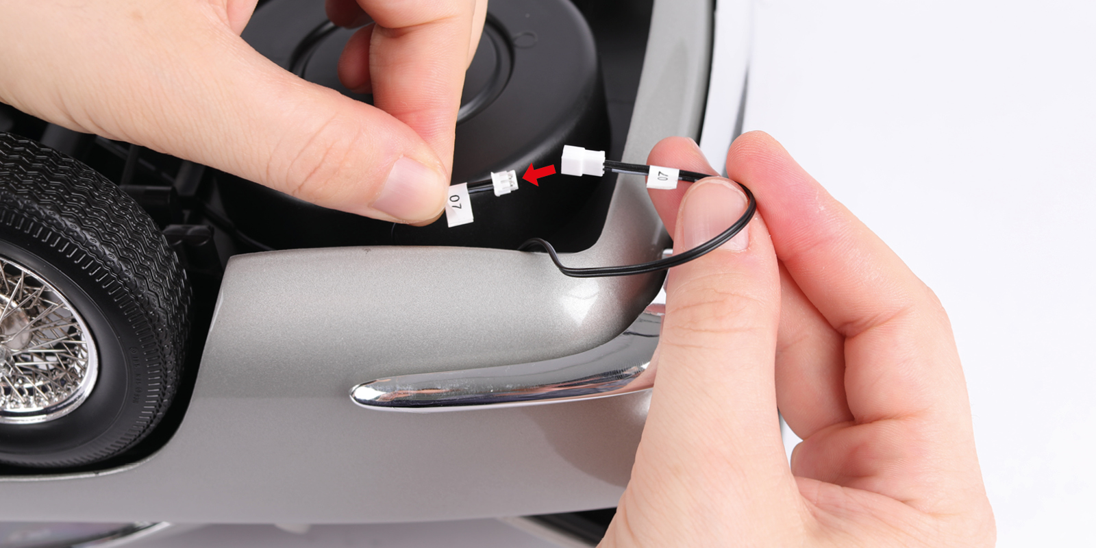
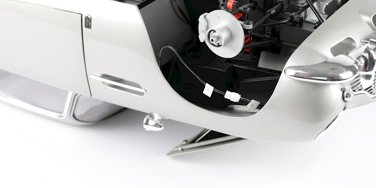
Step 8
Tuck the cables into the gaps as shown.
Step 9
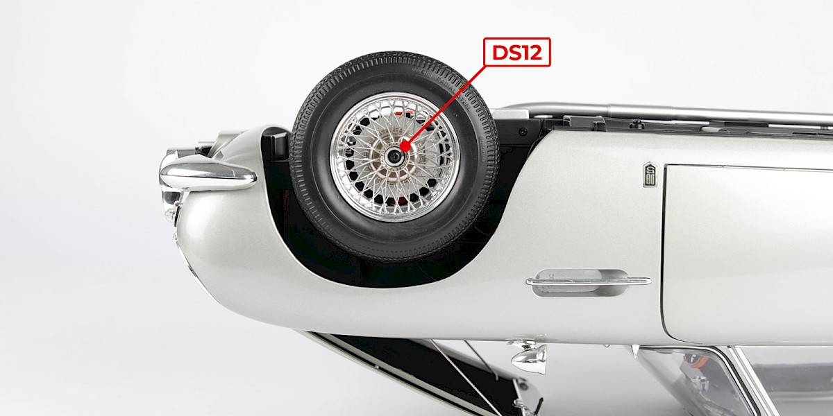
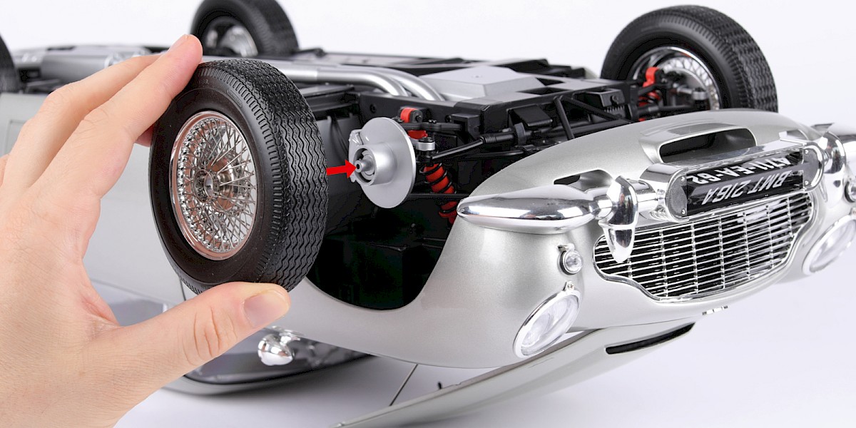
Fit the front right wheel (stage 004) and secure with 1x DS12.
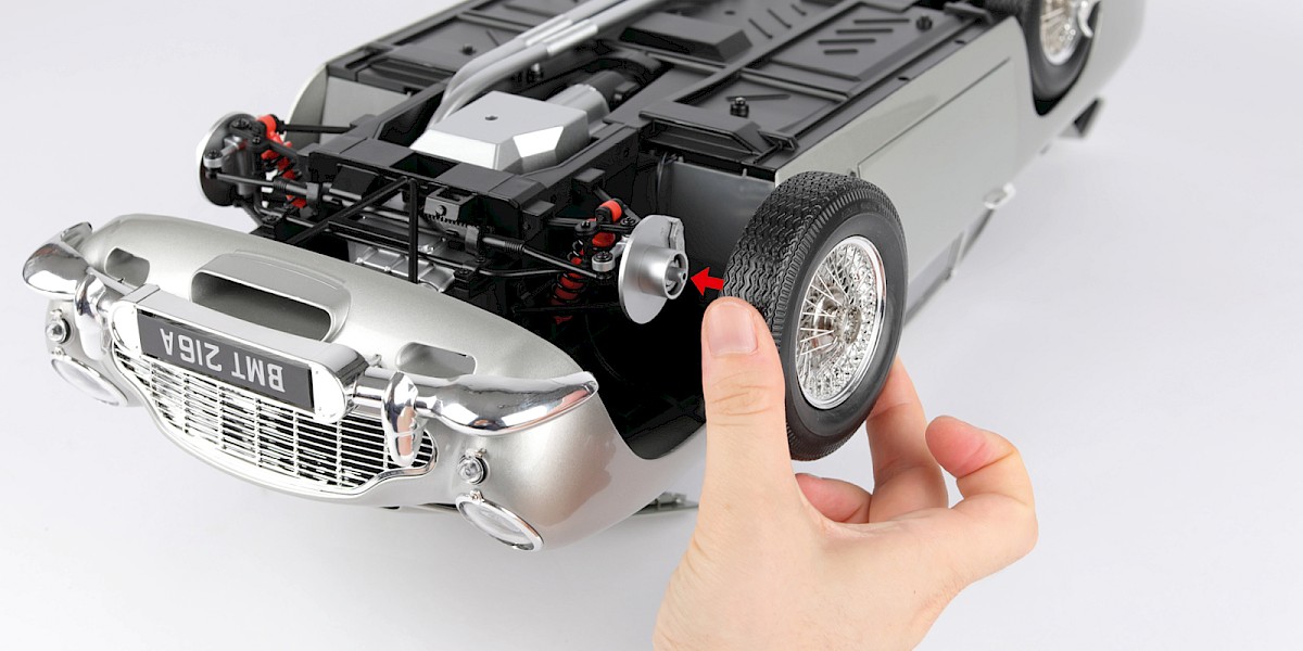
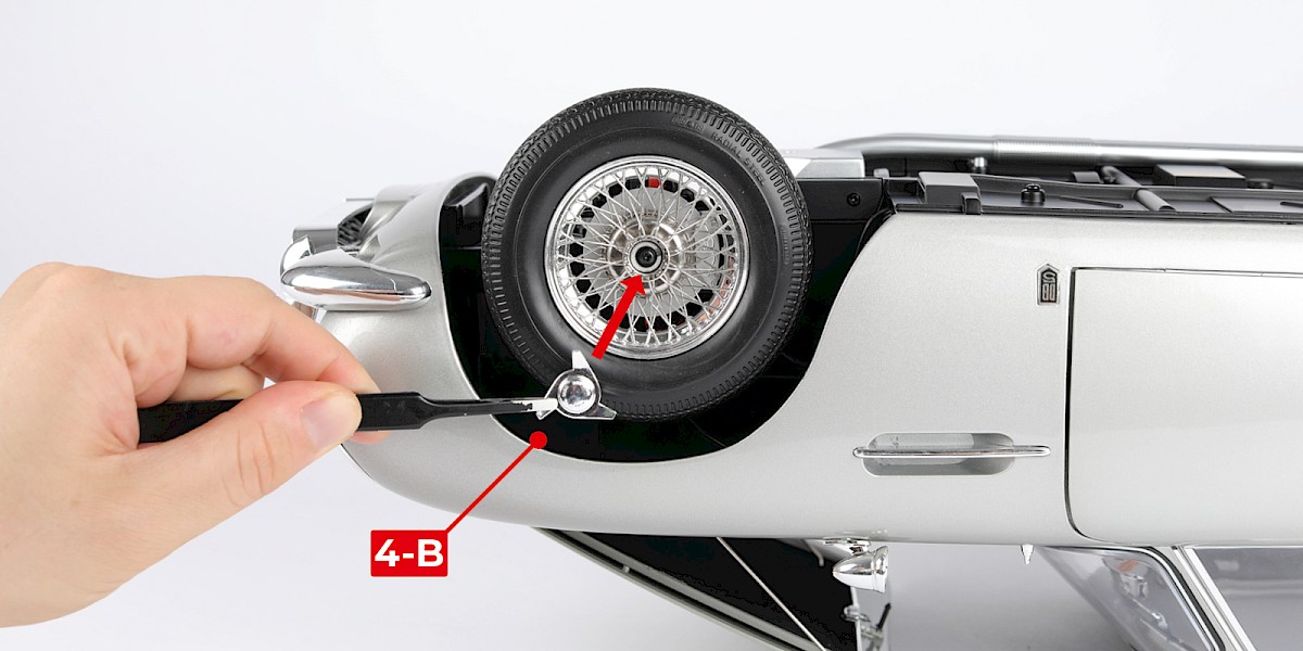
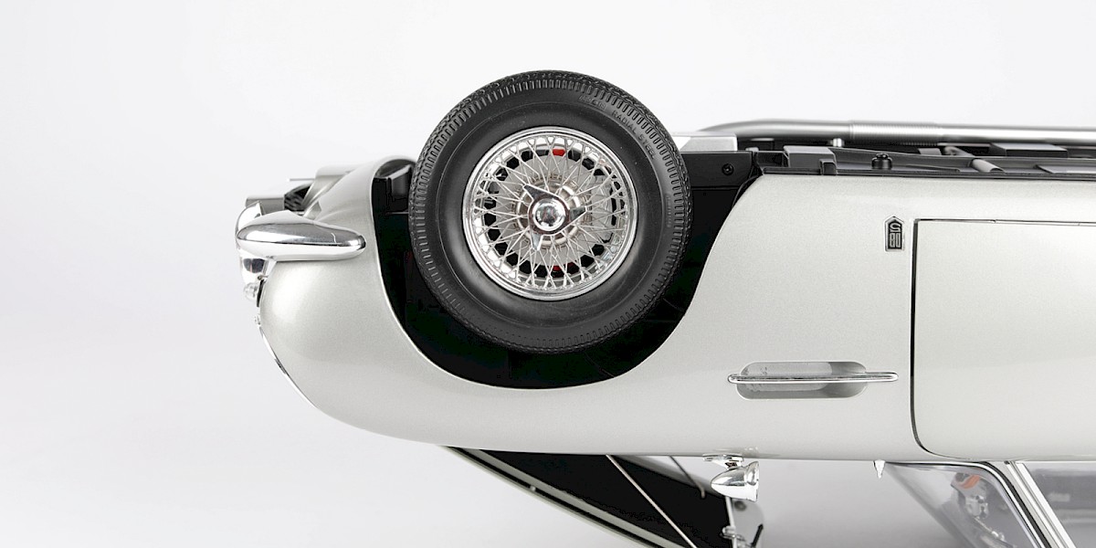
Step 10
Place the hub cap (4-B) in place.
Step 11
Fit the front left wheel (stage 029) and secure with 1x DS12.
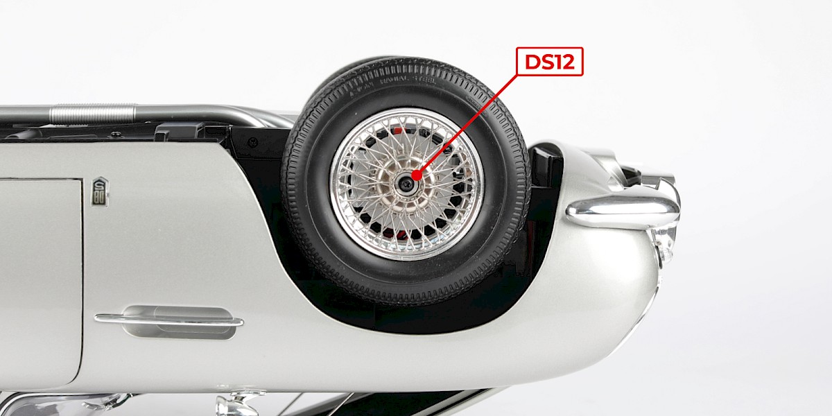
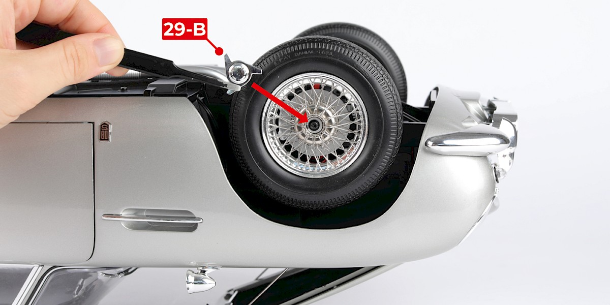
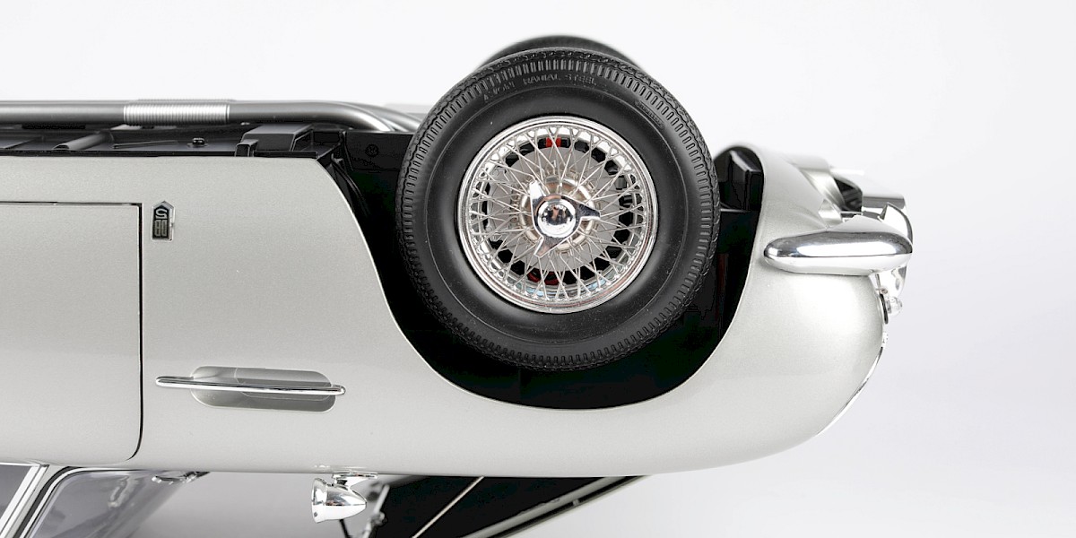
Step 12
Place the hub cap (29-B) in place.
Step 13
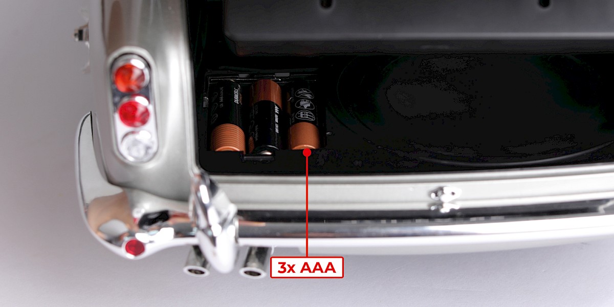
Testing the electrics
Open the boot and insert 3x AAA batteries into the battery compartment, then switch the power on.
Step 14
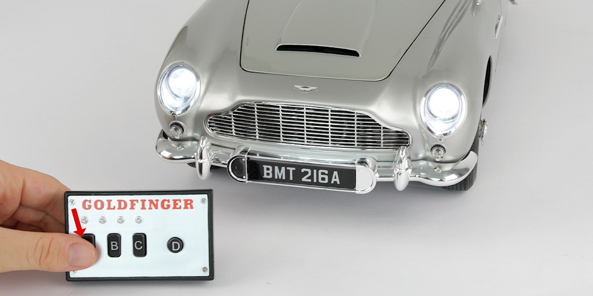
Press button A on the remote control. The headlights and brake lights will light up.
Step 15
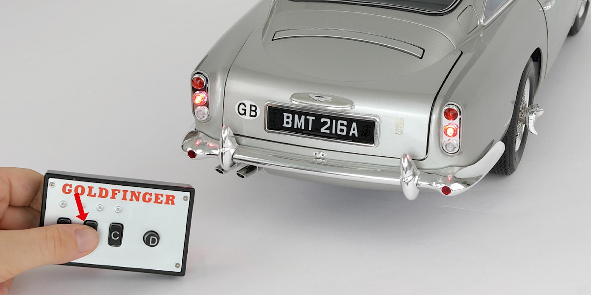
Press button B on the remote control. The brake lights will light up brighter.
Step 16
Press button C on the remote control. The dashboard lights will light up.
Step 17
Press button D on the remote control. The machine gun sound effect will play.
Press the buttons again to turn the function off. Once you have finished testing the electrics, switch the power off.
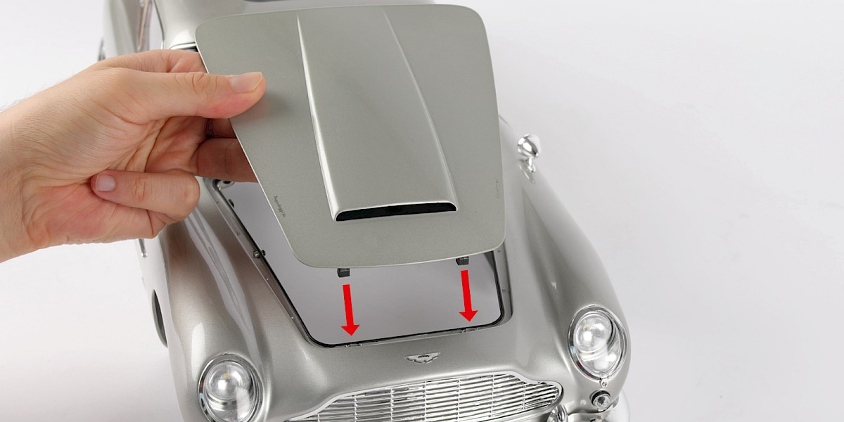
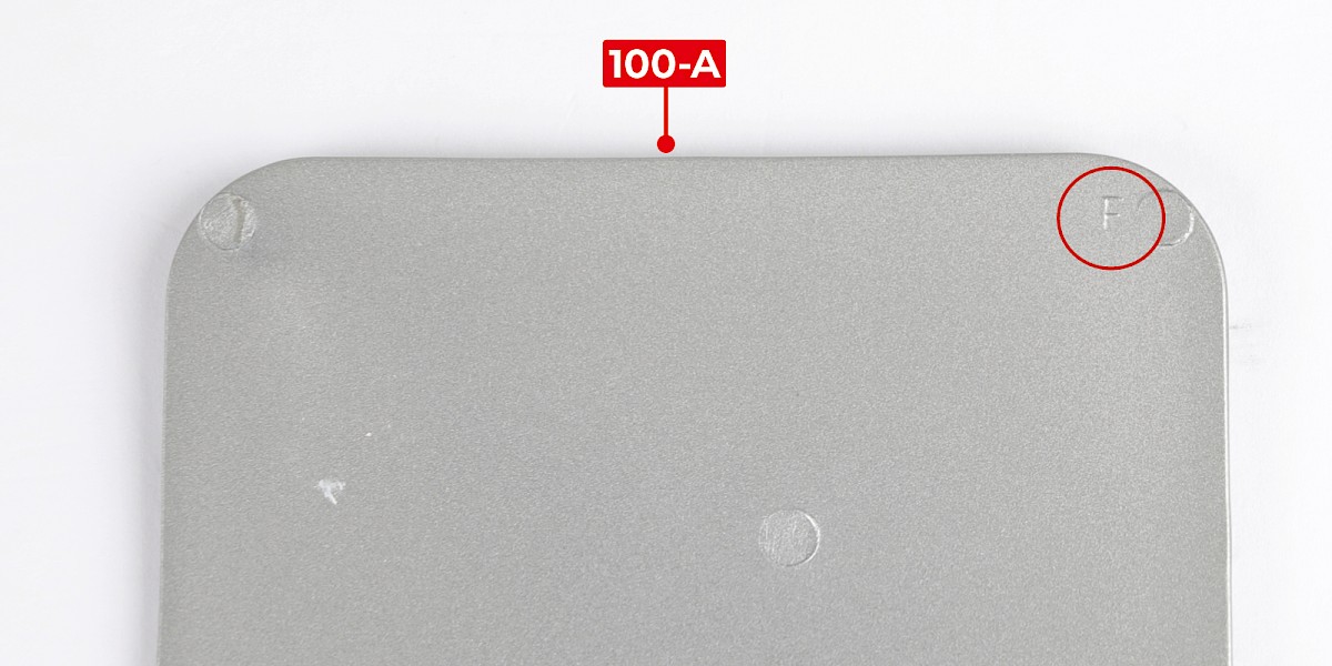
Step 18
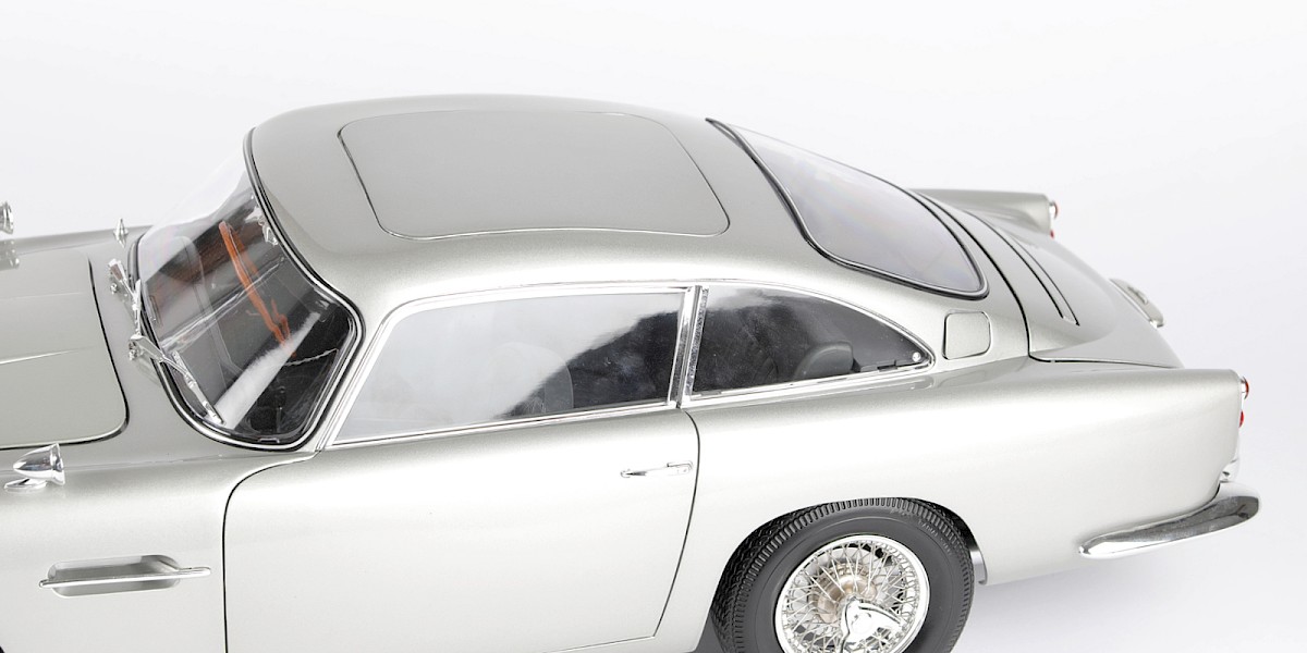
One corner of the roof panel (100-A) is marked with an F.
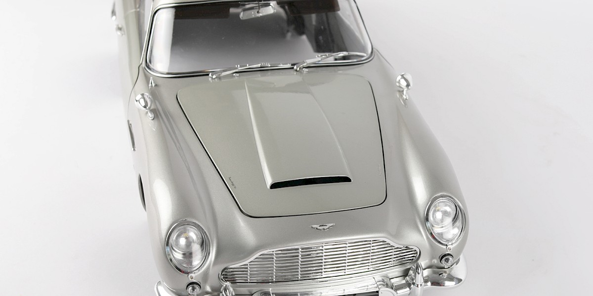
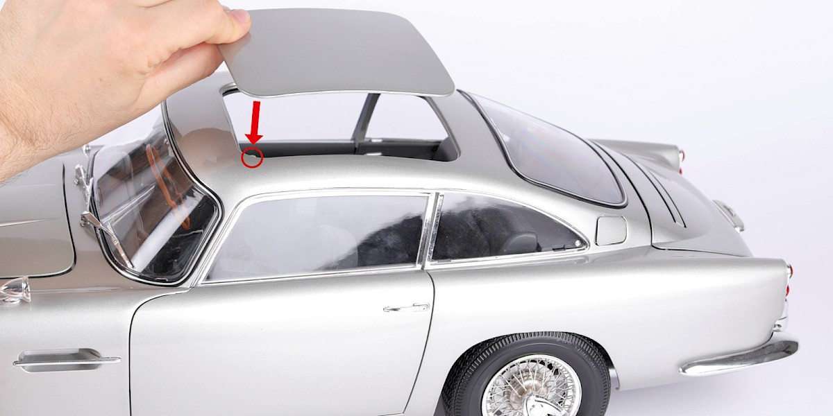
Step 19
Place the roof panel on the main body, matching the letters F (circled).
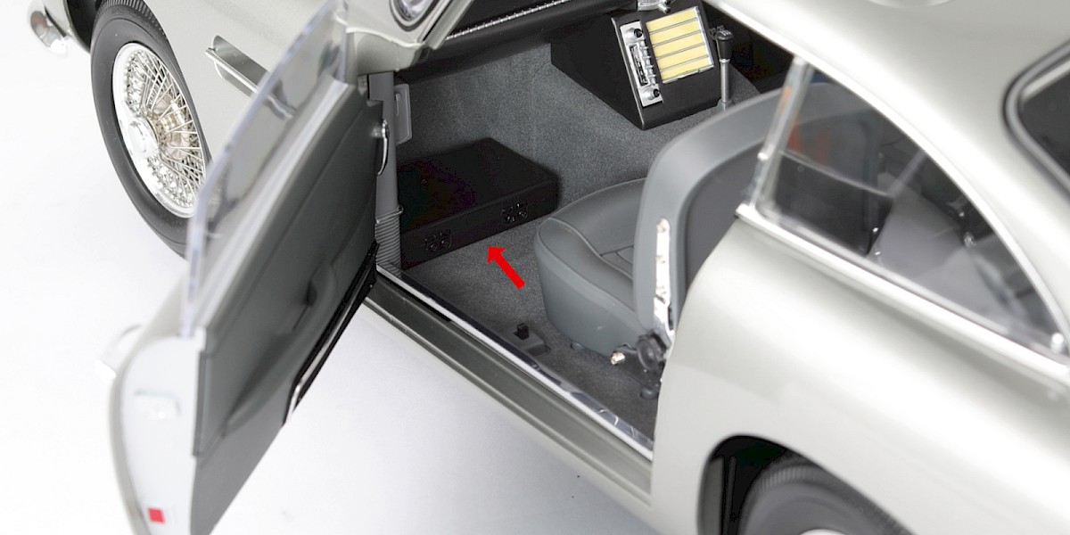
Step 20
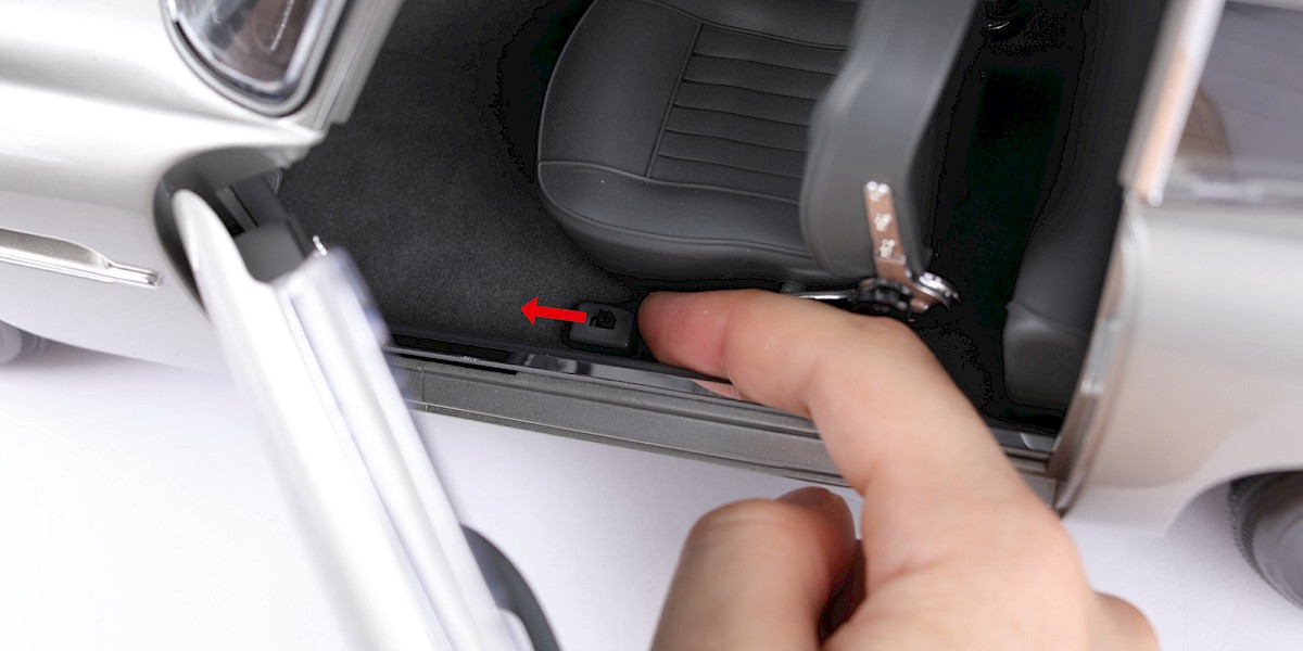
Place the weapons tray (stage 098) into the passenger footwell.
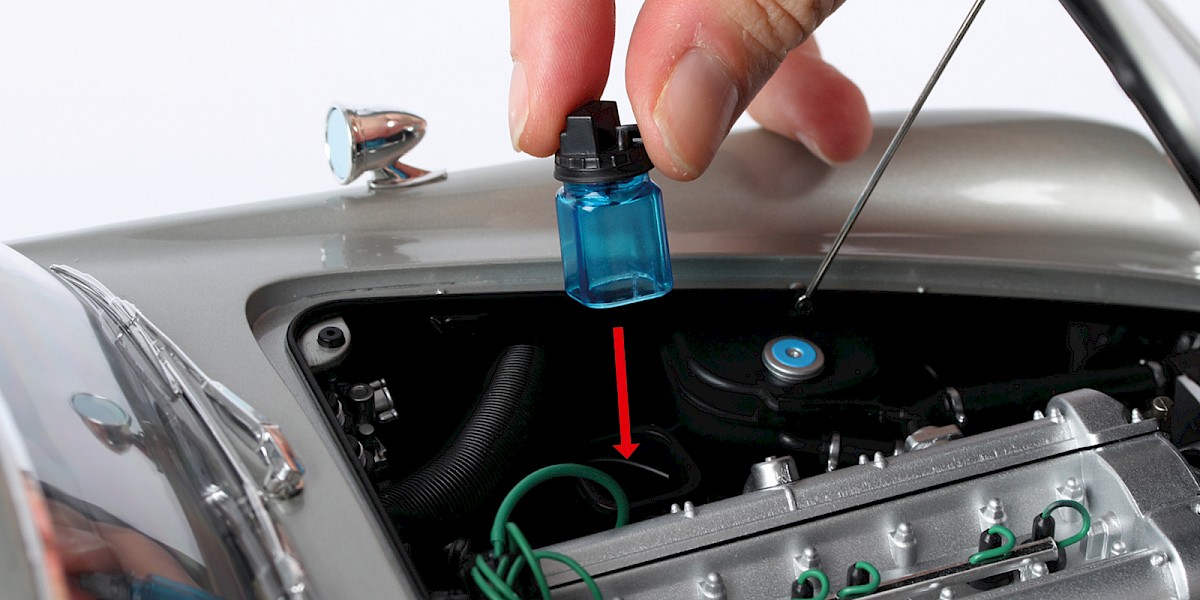
Step 21
If you placed the windscreen washer reservoir in a safe place in stage 062, insert it back into the holder.
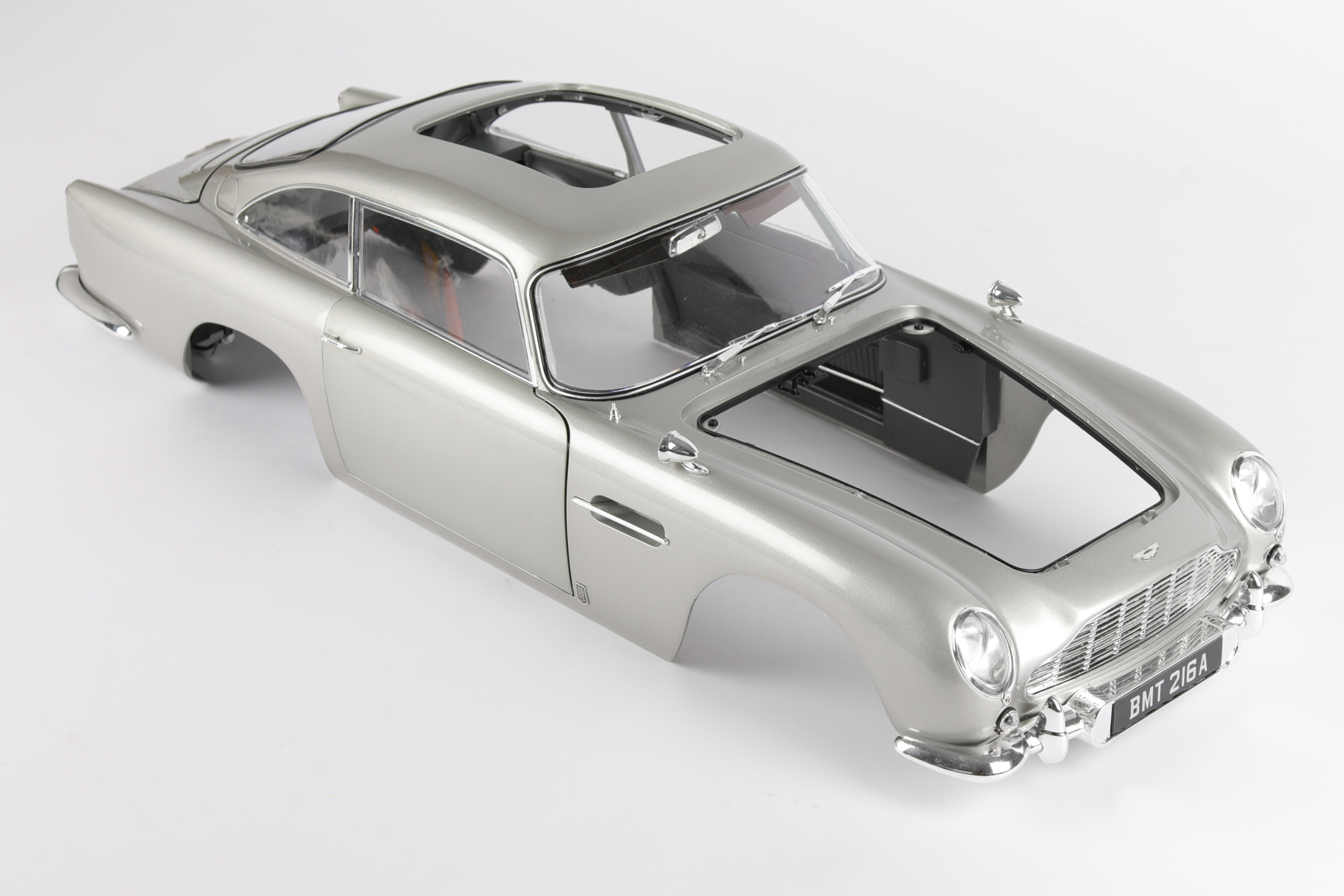
STAGE COMPLETE

Your model is now complete!
Don’t forget, as an Agora Advantage Club member you will have Reward points to redeem. You may now have enough points to enjoy a free pack 1 for your next model.