Pack 10
BUILD INSTRUCTIONS
Advice from the experts
Spare screws are included with each part. Occasionally, you may be instructed to keep spare or unused screws for a later stage. Keep these spares in a safe place and label them correctly.
Please make sure you don’t mix up the screws. They look quite similar, but the threads do vary slightly. Using the wrong screws may damage the parts. Only use the correct size screwdriver that fits the screw head firmly.
When securing parts together using multiple screws, fit each screw loosely to ensure all the parts are correctly aligned before gently tightening them firmly, but not overtight, in the order in which you placed them.
The screwdriver can be magnetized by stroking it with a magnet (fridge magnet, etc.) enabling it to hold the screws and make assembly easier.
If a screw is tight going into a metal part, do not force it as you may shear the head off. Remove it and put a tiny smear of Vaseline, soap or light oil on the thread. That will lubricate it and make it easier to tighten.
Some parts will require a little glue for assembly. Please apply glue sparingly and use a cocktail stick so that you don’t use too much nor apply the glue too heavily. We recommend superglue gel or Extra Thin Liquid modeling glue. Where possible, parts should be test-fitted in place before gluing.
Make sure you have good ventilation when using adhesives and to replace caps firmly.
Use a magnet to help find screws that have fallen on the floor.
Use masking tape to hold parts temporarily in place.
Cut parts from a sprue (framework) with side cutters or a craft knife. Side cutters tend to be easiest.
During the course of this build, you will receive many pieces that you will assemble immediately – following the instructions in the corresponding stage – and other pieces that you should store safely to one side, for use in future assembly stages.
Always protect the paint finish on components by placing a cutting mat, sheet of white paper or soft cloth on your work surface.
When plugging cables in, ensure the power is switched off. Tweezers can be used to fit the PVC cables by gripping carefully around 5mm from the end of the cable. If a cable needs to be removed from a socket, do not pull on the cable as this could damage the connection. Grip the plug with tweezers to remove it.
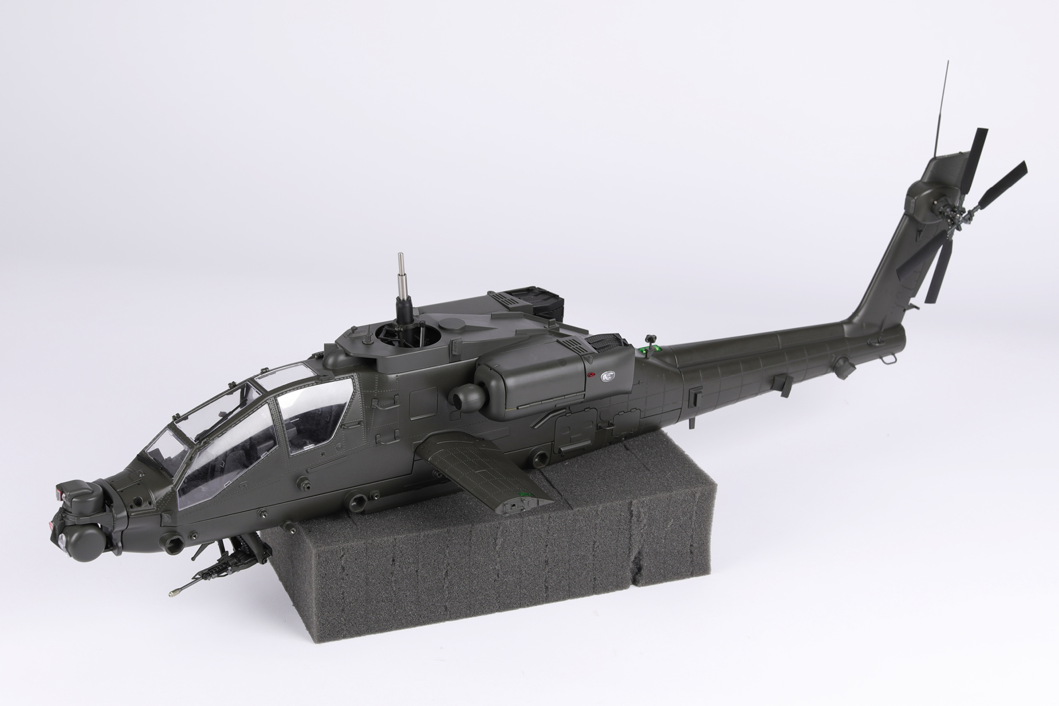
Left and Right! When building your AH-64 Apache, the left- or right-hand side refers to that side as if you are sitting in the cockpit.
![]() When you see this symbol, pay attention to the instruction text in bold and check the orientation of the parts in the image as this will be particularly important for assembly in later stages.
When you see this symbol, pay attention to the instruction text in bold and check the orientation of the parts in the image as this will be particularly important for assembly in later stages.
WARNING: Some parts are assembled using magnets. These magnets can cause serious injury if they are swallowed. Keep away from children. If you suspect a magnet has been swallowed, seek medical help straight away.
This is not a toy. Not suitable for children under 14 years old due to small parts. Adult supervision required.
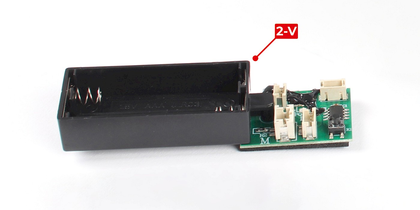
In this pack you will plug the cables into the circuit board. Please ensure all cables are tested using the tester (2-V) throughout this pack.
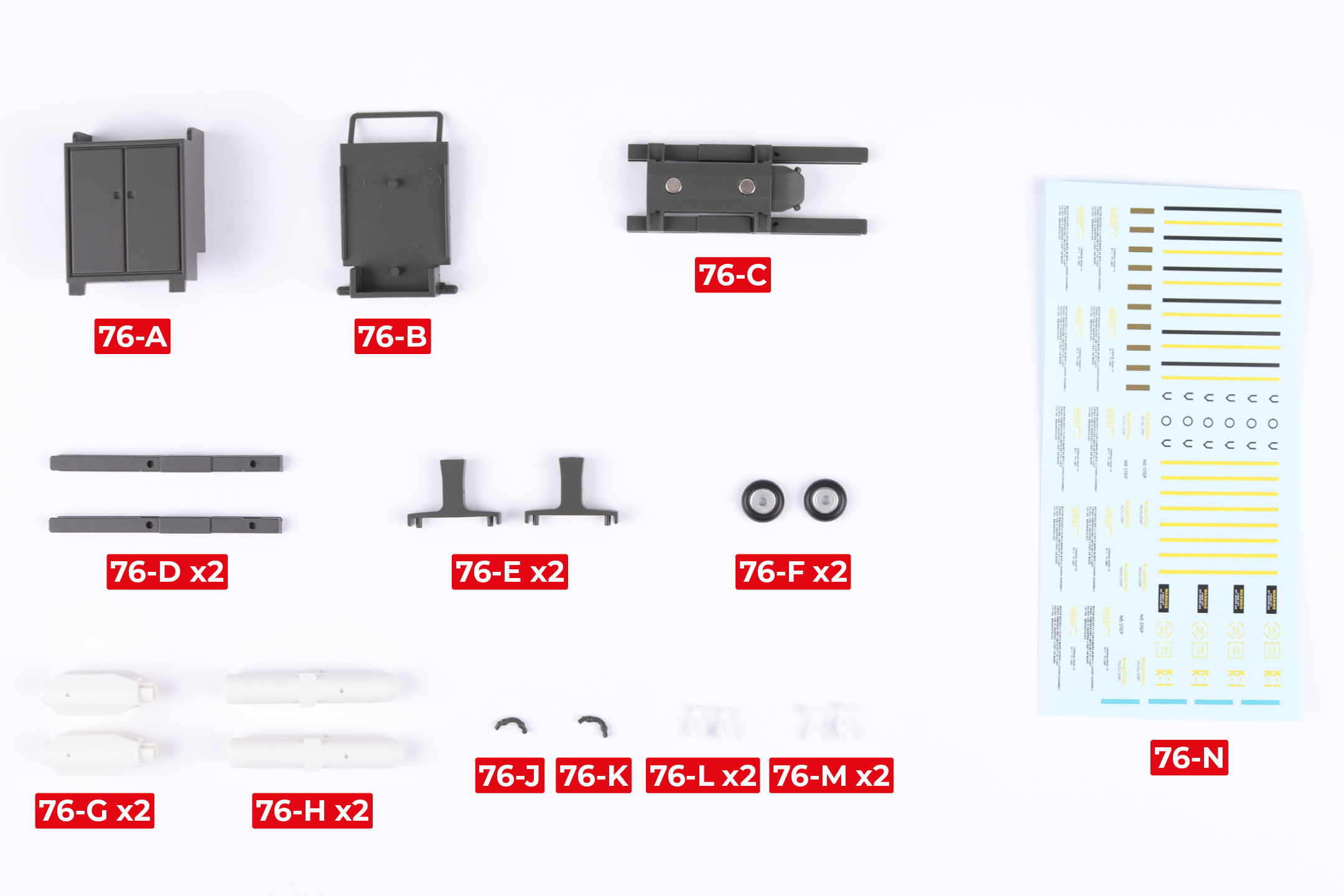
PARTS LIST
| 76-A | 76-H x2 |
| 76-B | 76-J |
| 76-C | 76-K |
| 76-D x2 | 76-L x2 |
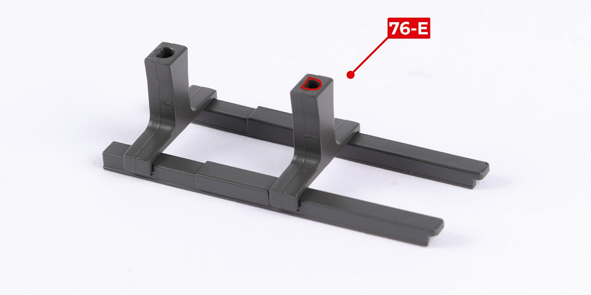
| 76-E x2 | 76-M x2 |
| 76-F x2 | 76-N |
| 76-G x2 |
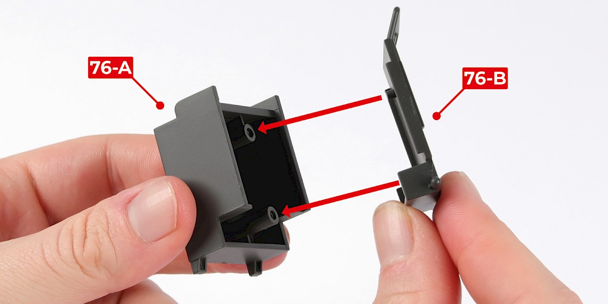
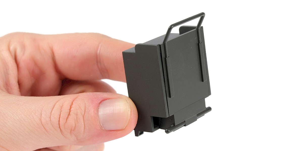
Step 1
Fit 76-B to 76-A.
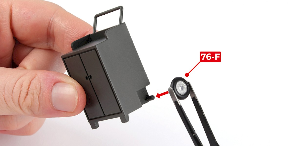
Step 2
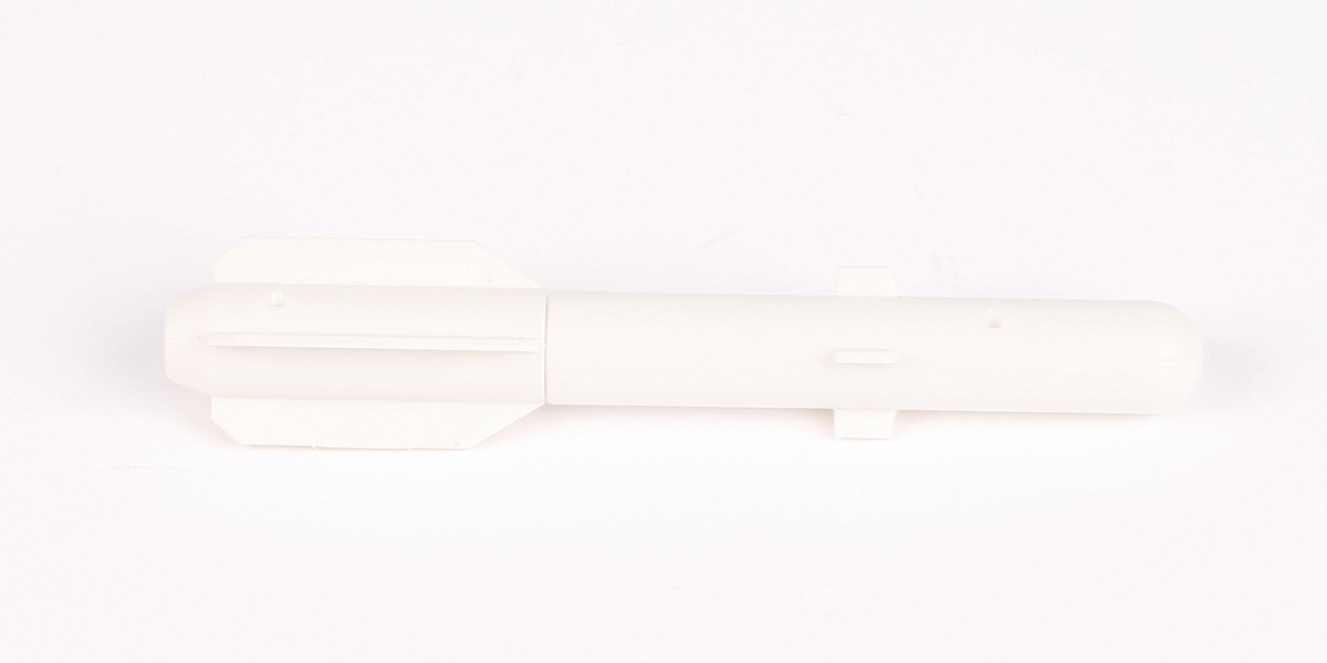
Fit 76-F to the assembly.
You may need to remove excess paint before fitting the parts together.
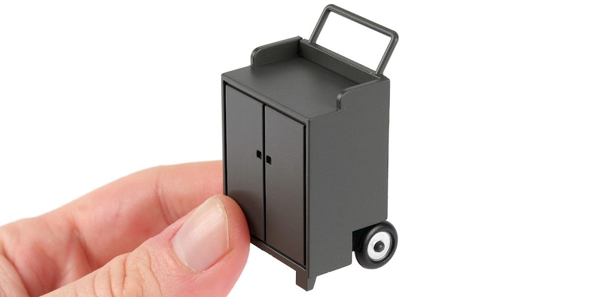
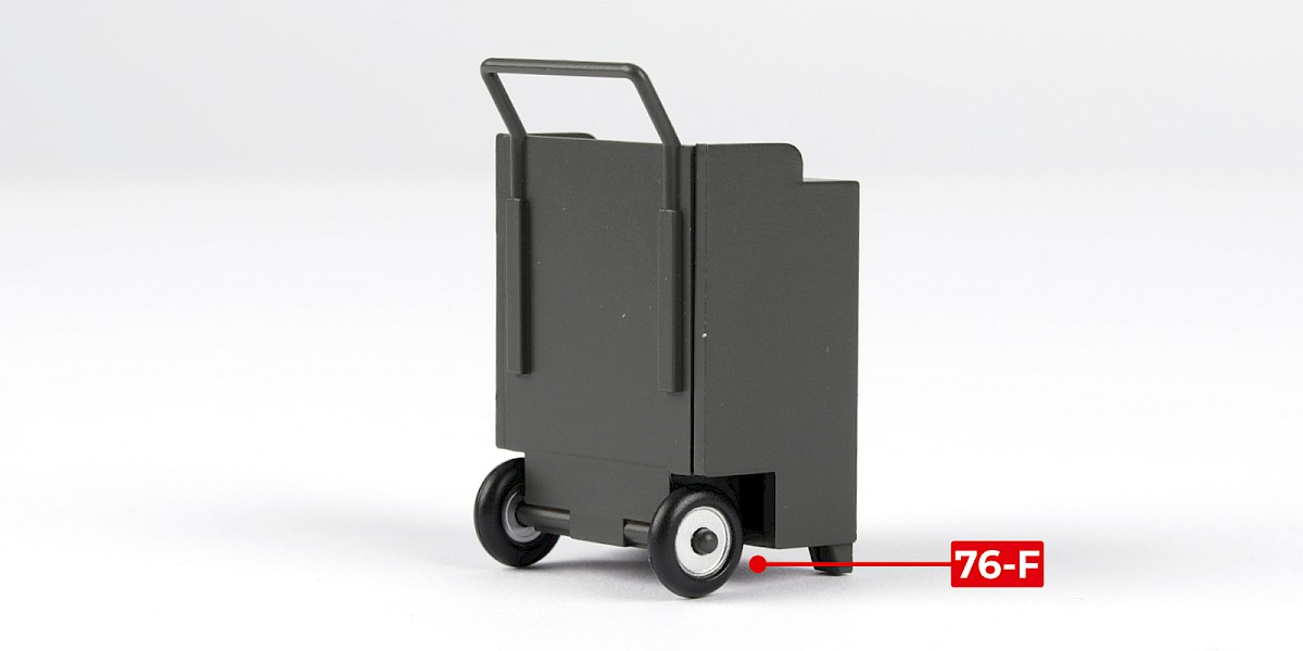
Step 3
Fit the other 76-F to the assembly.
Step 4
Encaje la pieza 76-G en la pieza 76-H.

Step 5
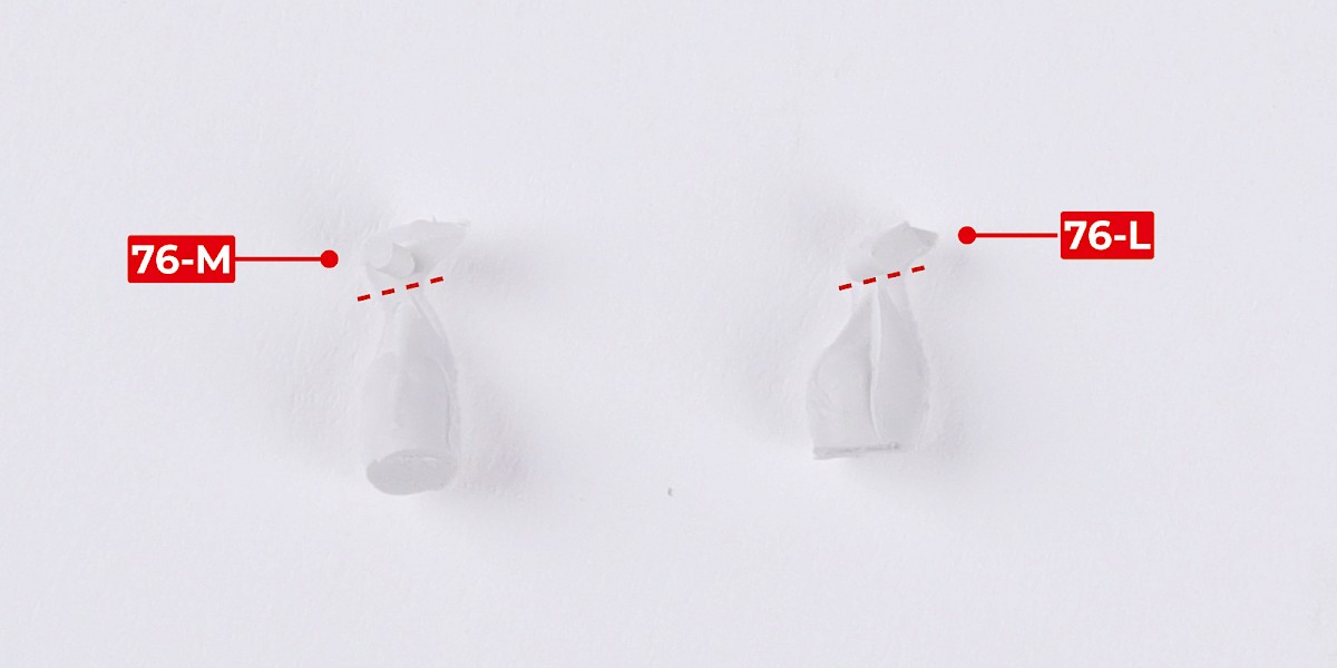
Cut parts 76-M and 76-L off the sprues.
Step 6
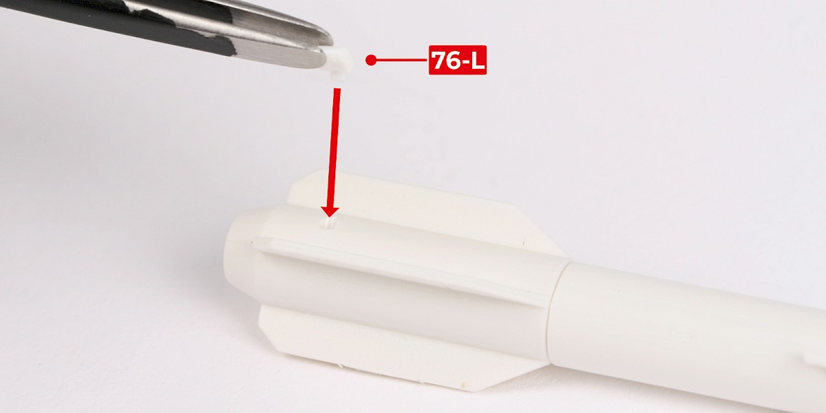
Glue 76-L to the assembly.

Step 7
Glue 76-M to the assembly.


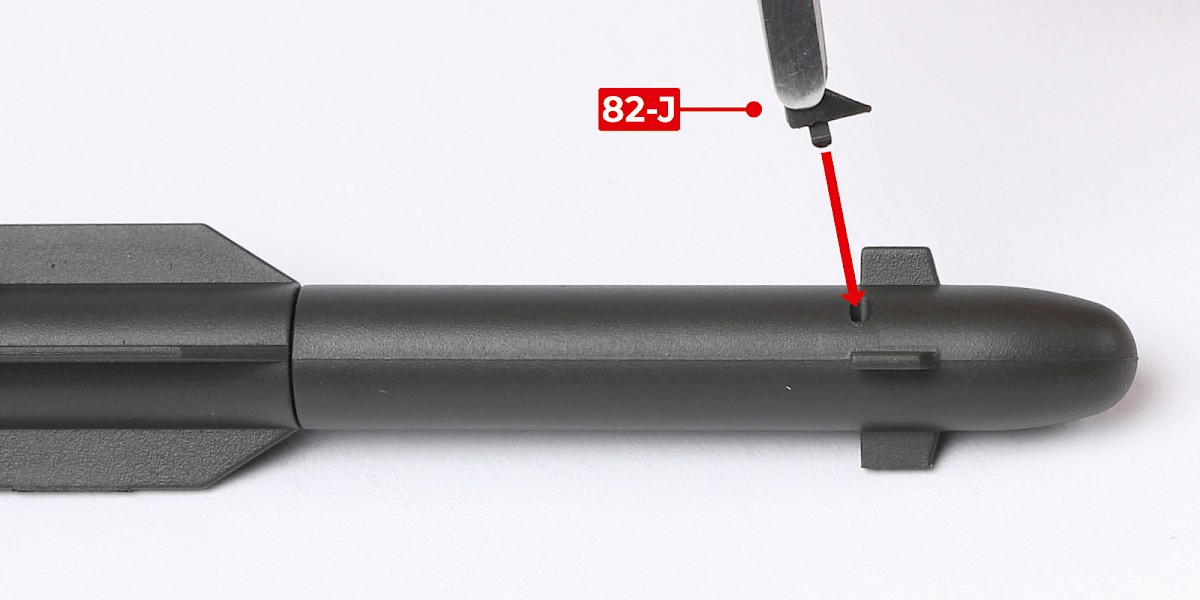
Step 8
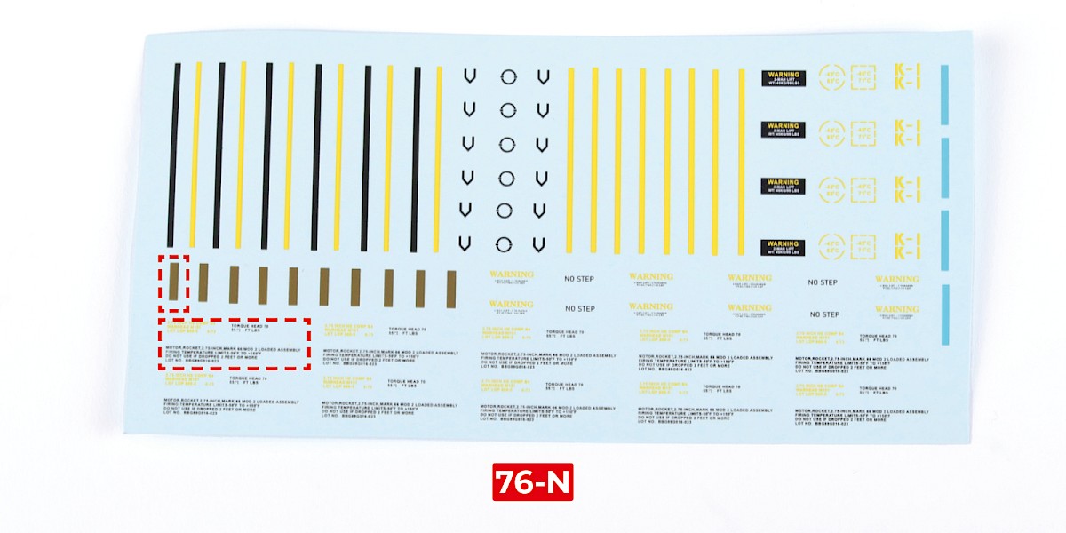
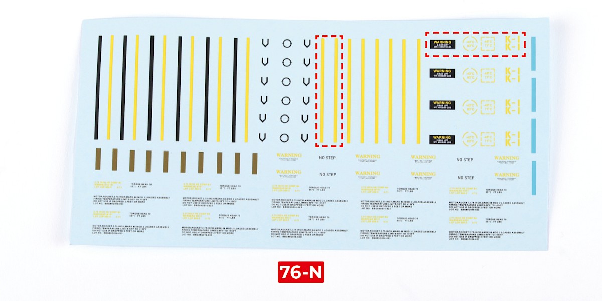
Cut the decals outlined in red from 76-N.


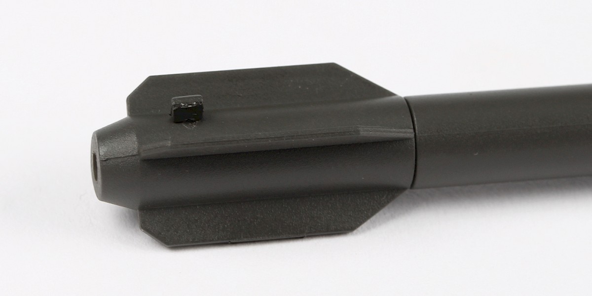
Step 9
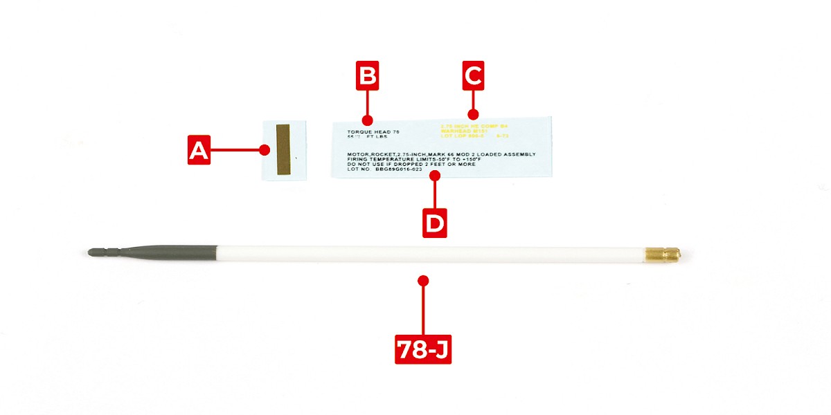
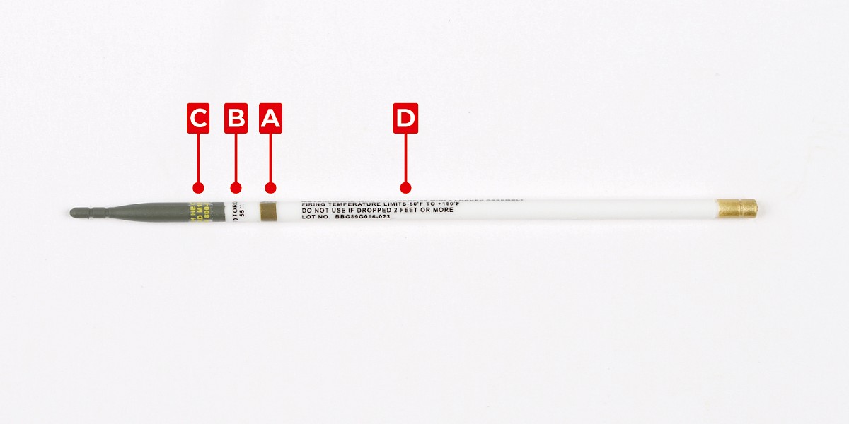
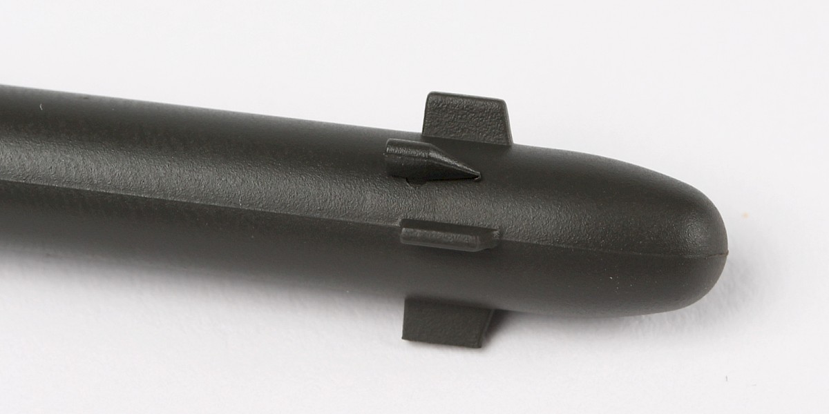
Apply decals A, B, C and D to the missile.
Repeat this process to assemble two missiles.


Step 10
Glue one of the missiles to 76-C.


Step 11
Glue a second missile in the same way.
Step 12
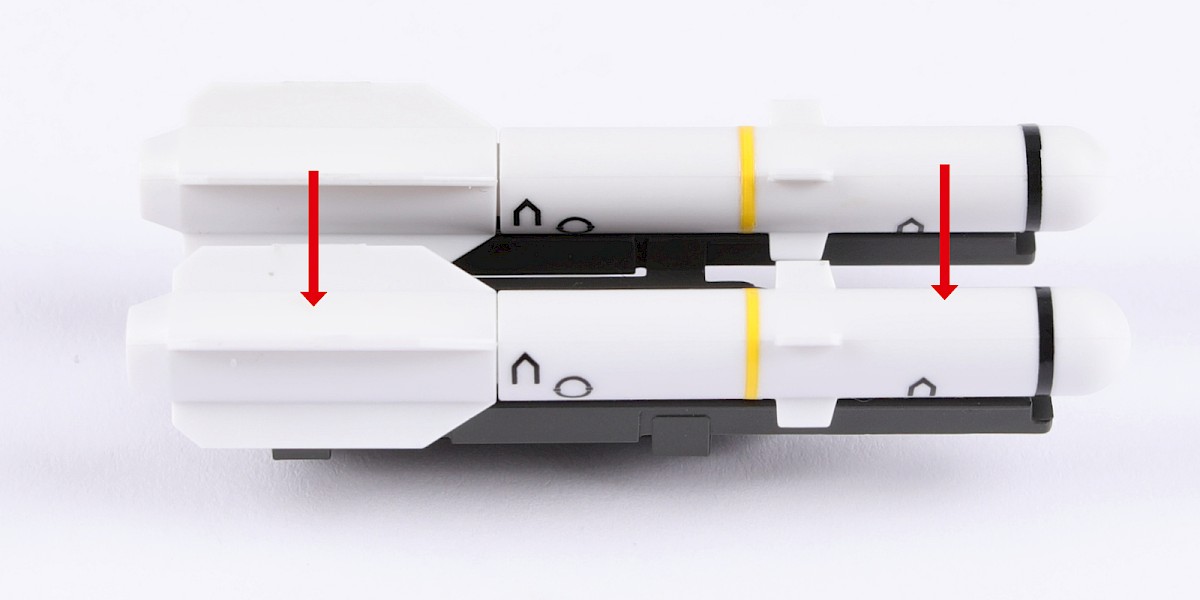
Fit 76-E to 76-D. Make sure the parts are in the orientation shown. The recesses on parts 76-D (blue arrows) should face outwards.


Step 13
Fit another 76-E as shown.
Step 14
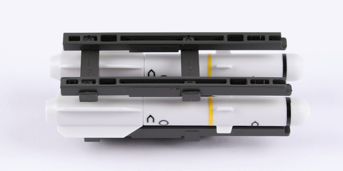
Fit the two assemblies together.

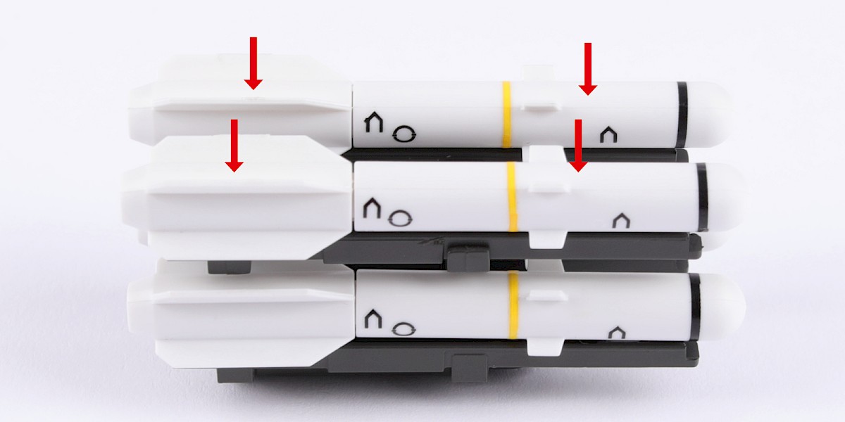
Step 15
Glue two missiles (stage 70) to the assembly.
Step 16
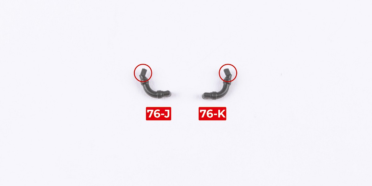
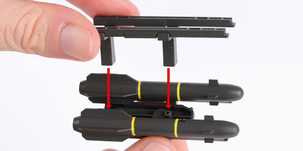
Parts 76-J and 76-K have shaped fittings.
Step 17
Fit 76-J to the assembly.


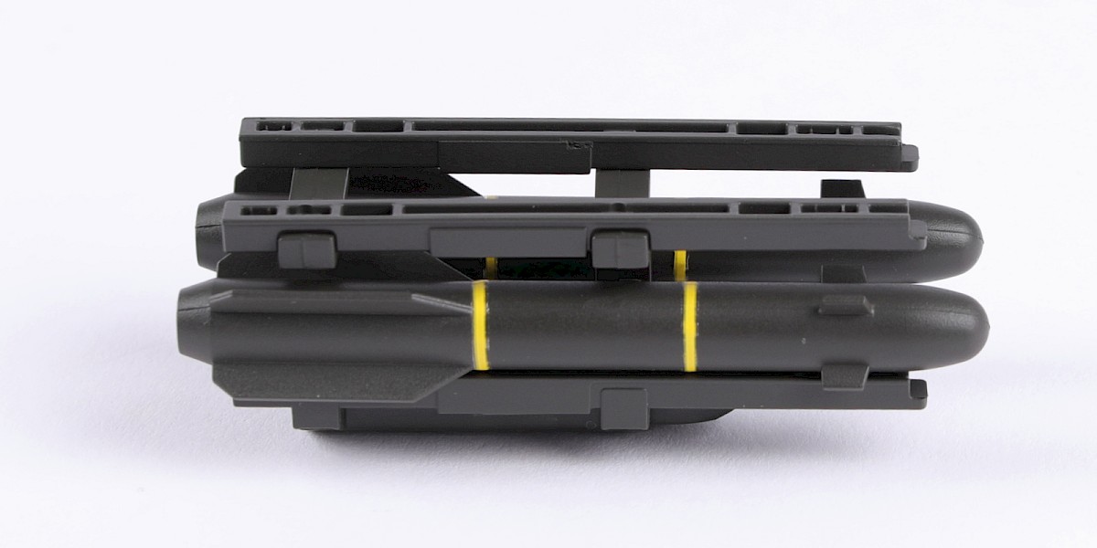
Step 18
Fit 76-K to the assembly.

Step 19
Cut the decals outlined in red from 76-N.


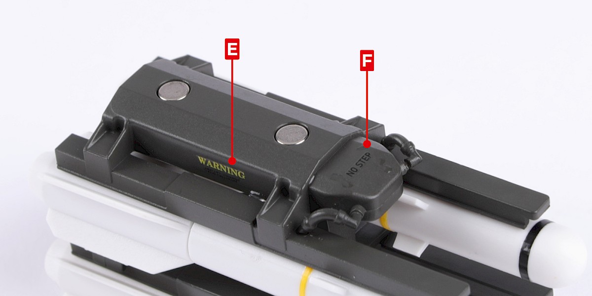
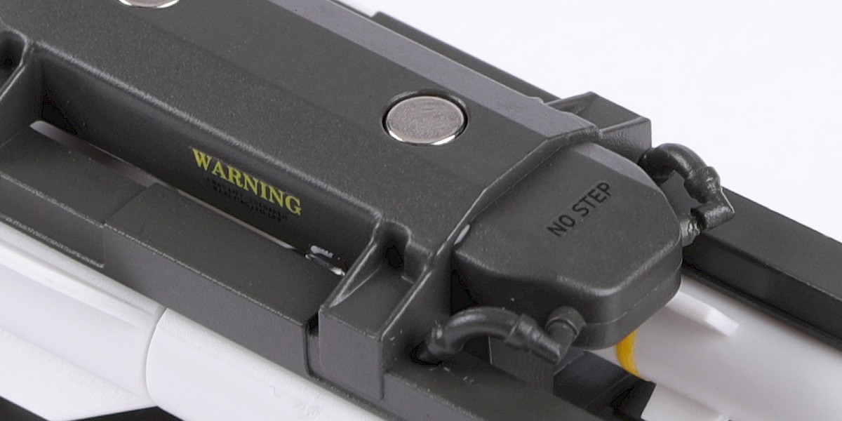
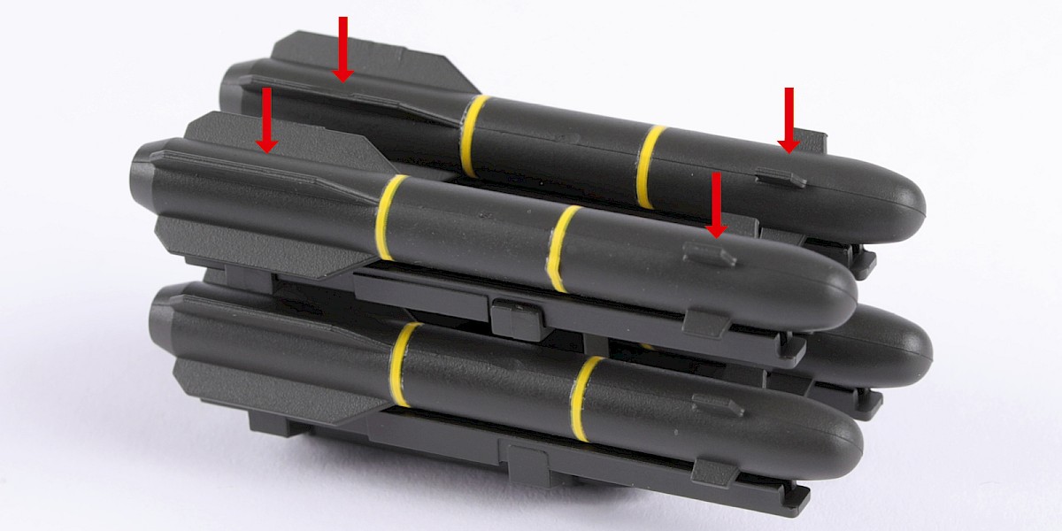
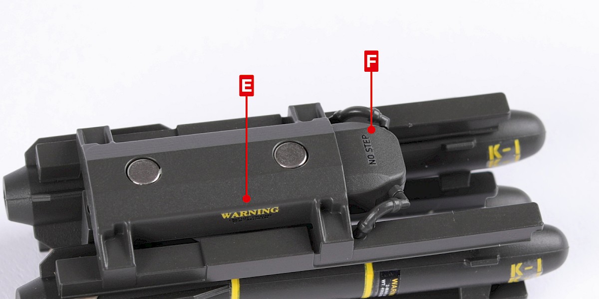
Step 20
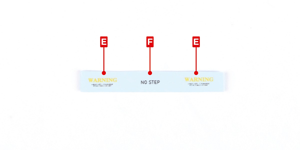
Apply decals E and F to the assembly.
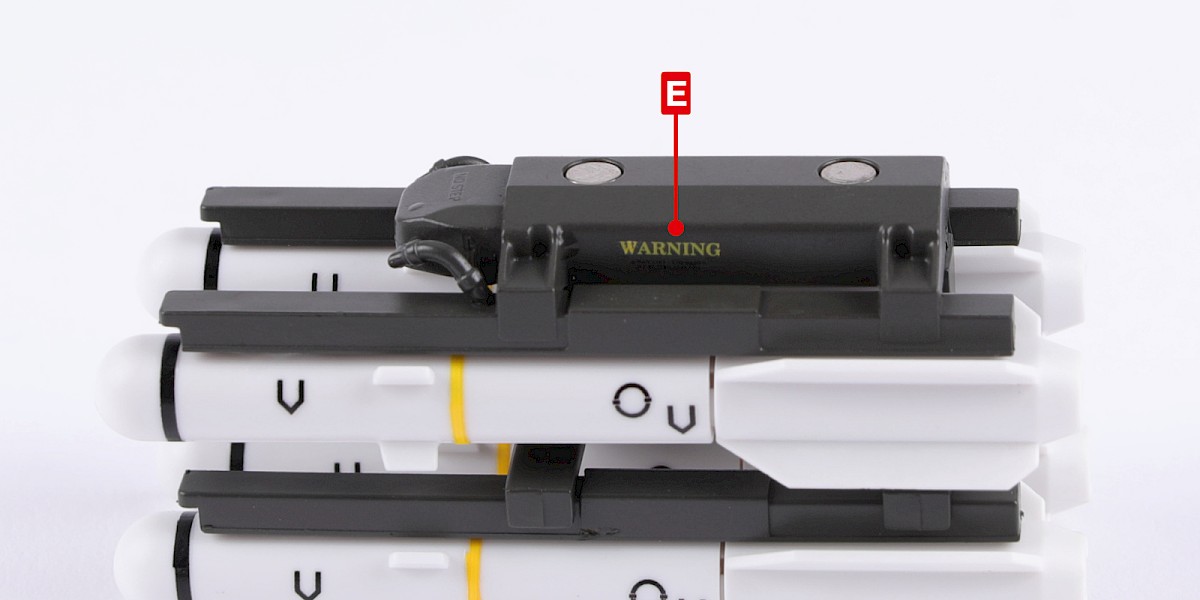
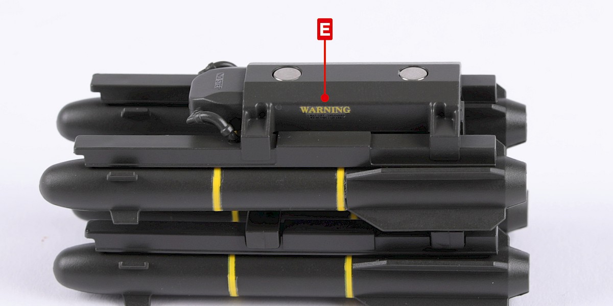
Step 21
Apply decal E to the other side.
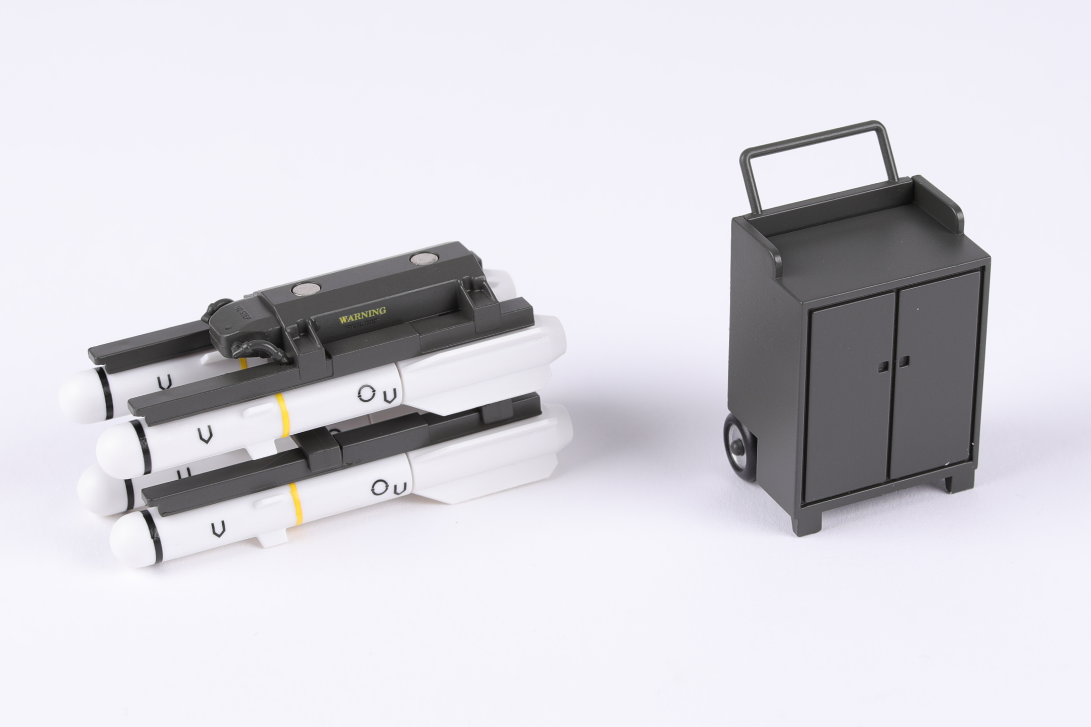
STAGE COMPLETE
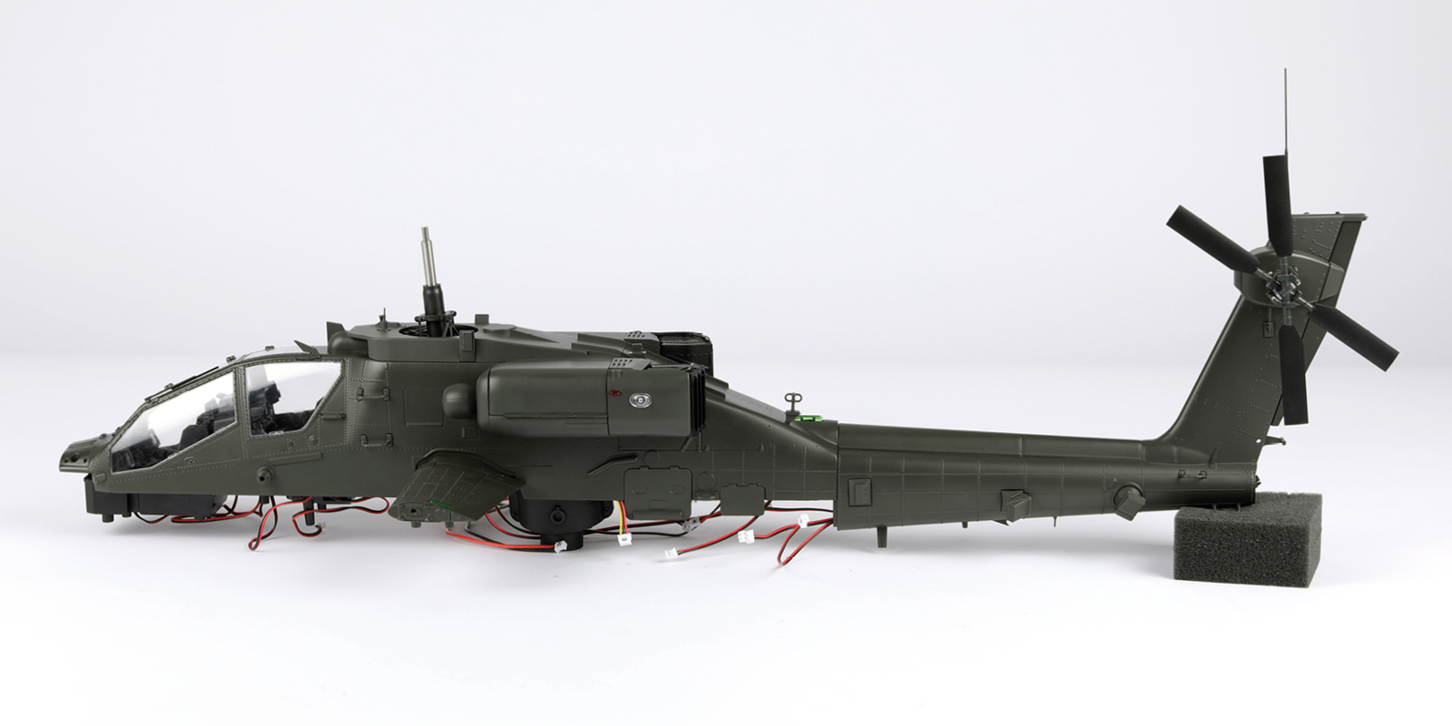
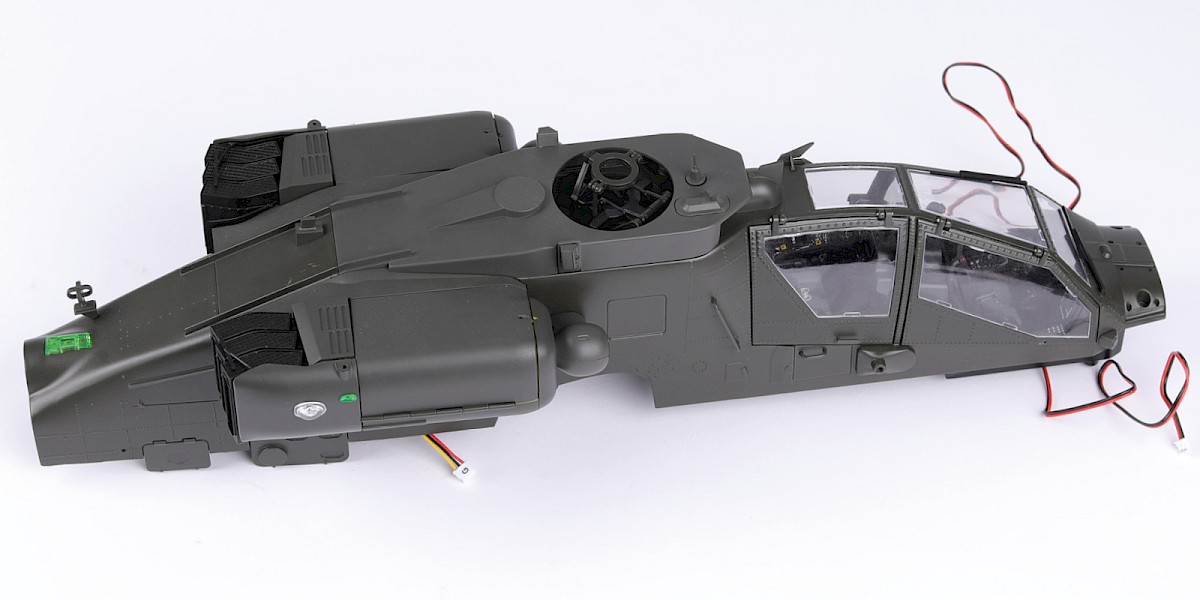
In this stage you will fit the engine nacelles to your model.
If you chose to build the modified upward-facing exhaust (Version 1), follow this stage.
If you chose to build the original exhaust (Version 2), follow Stage 77-v2.
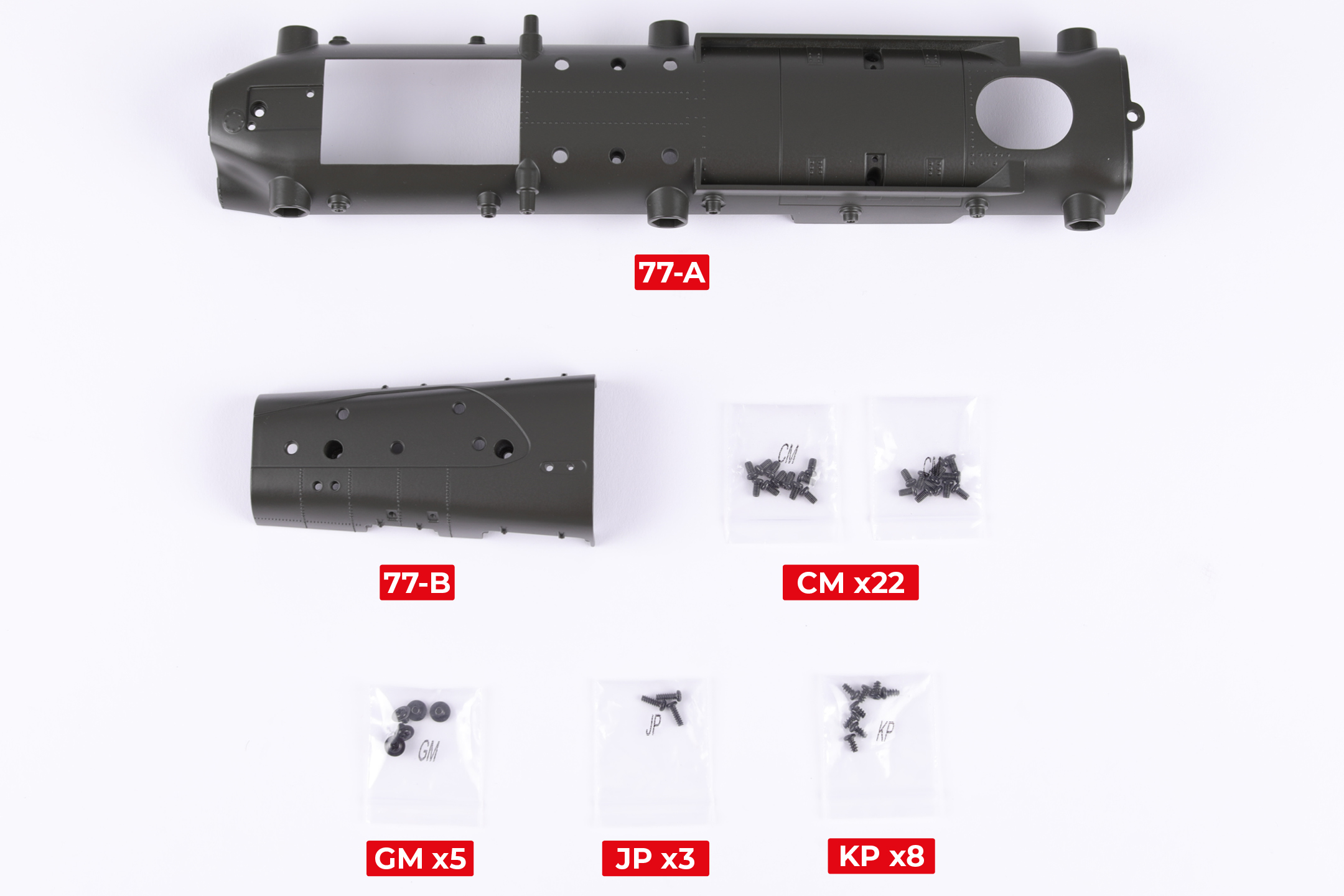
PARTS LIST
| 77-A | GM x5 |
| 77-B | JP x3 |
| CM x22 | KP x8 |
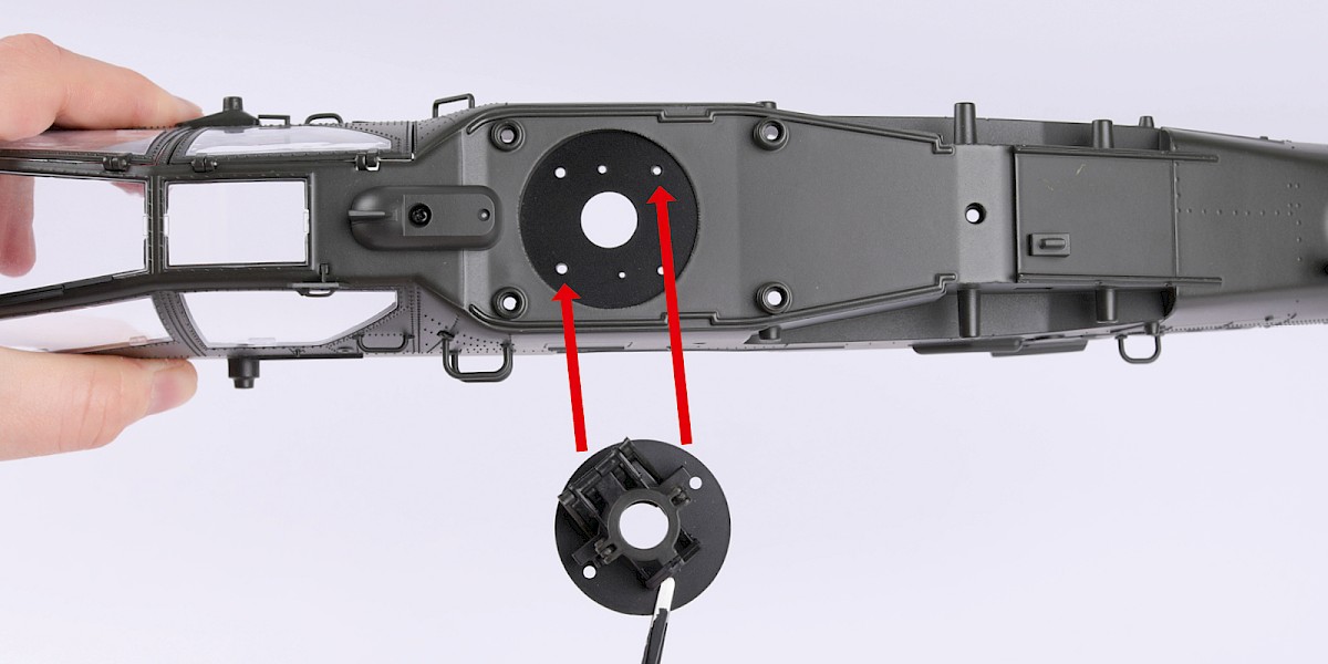
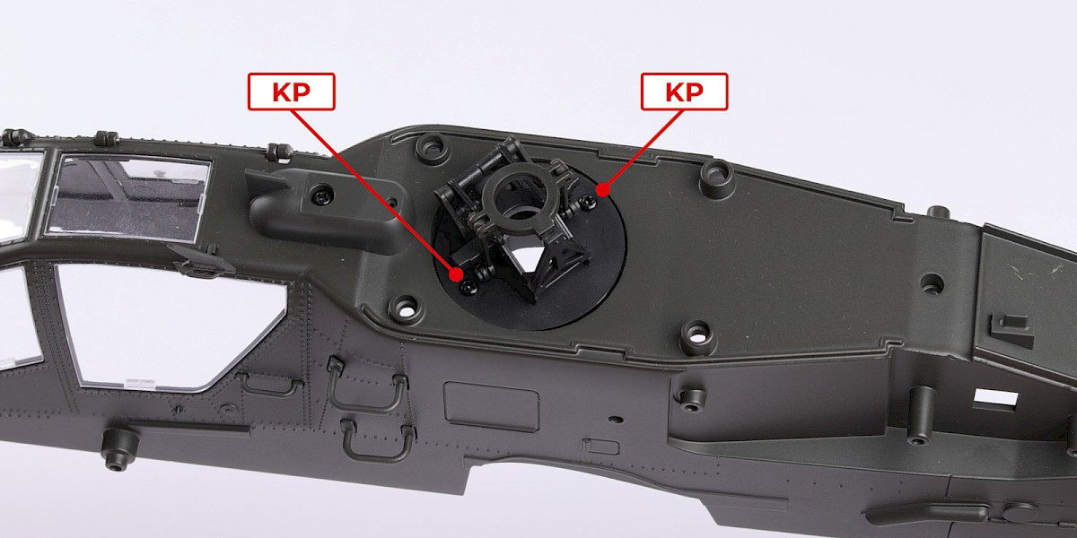
Step 1
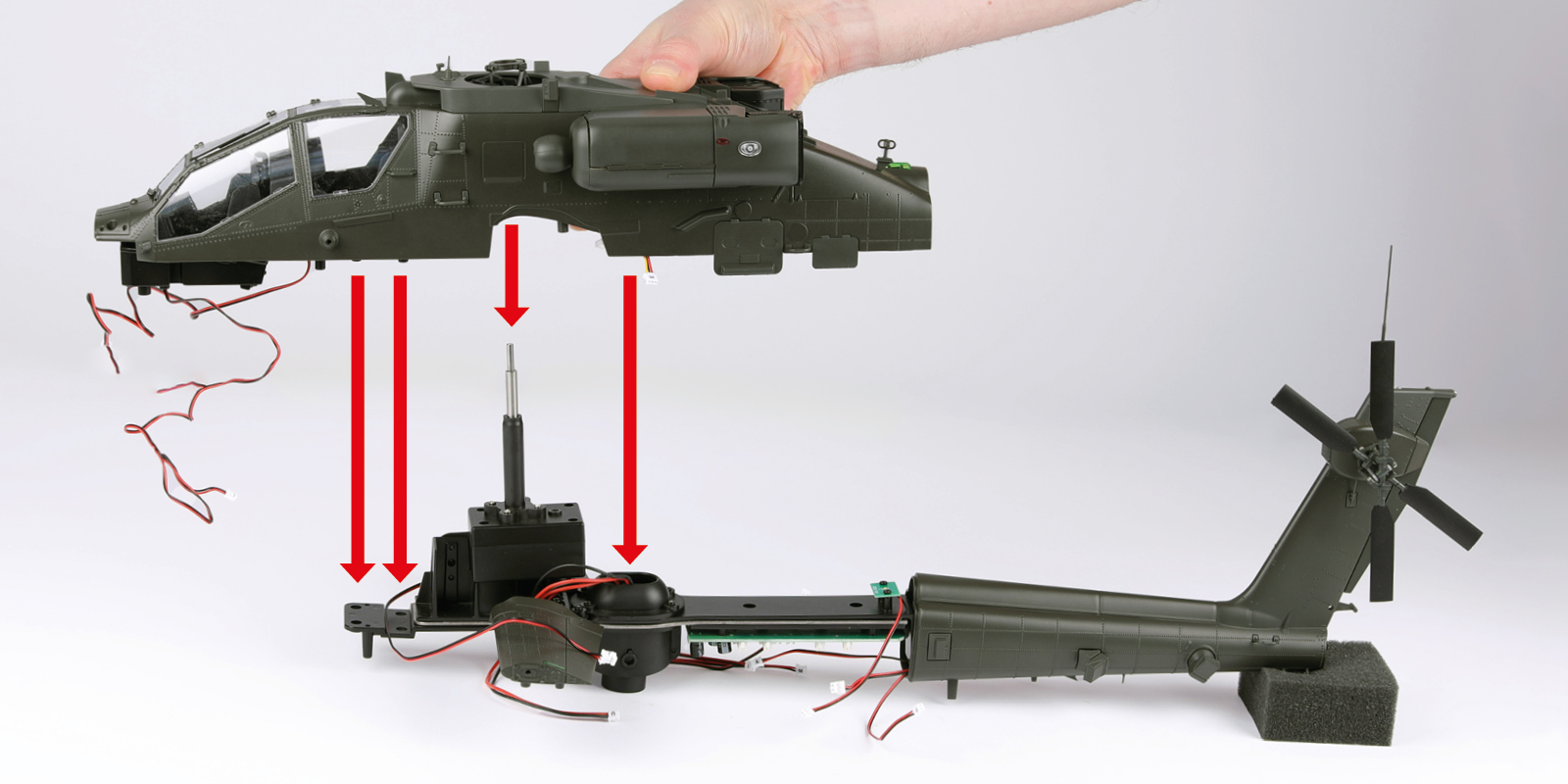
Fit the lower swashplate (stage 34) to the fuselage assembly.
Secure with 2x KP.
Step 2
Fit the top of the fuselage (stage 35) to the assembly.
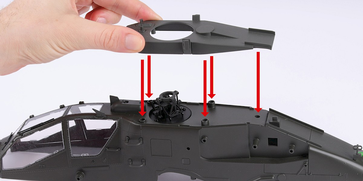
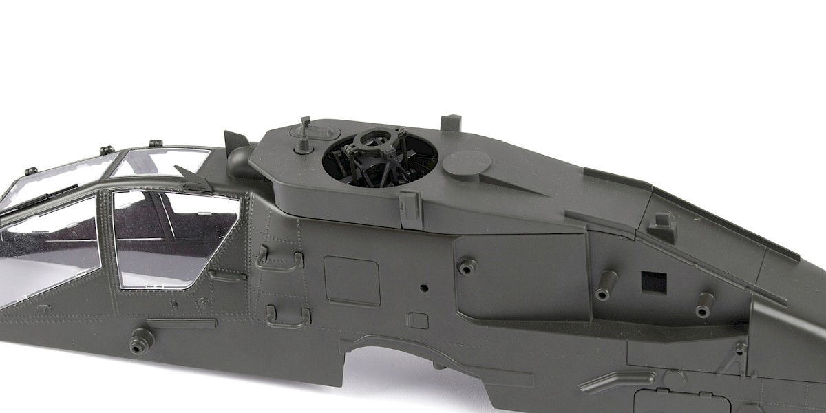
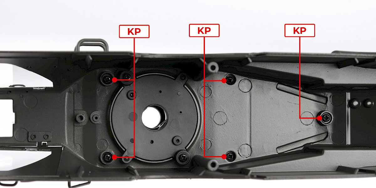
Step 3
Secure from underneath with 5x KP.

Step 4
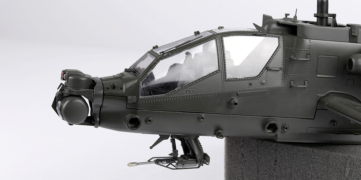
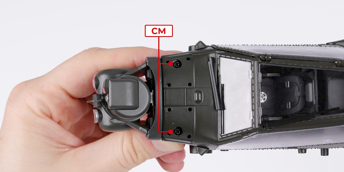
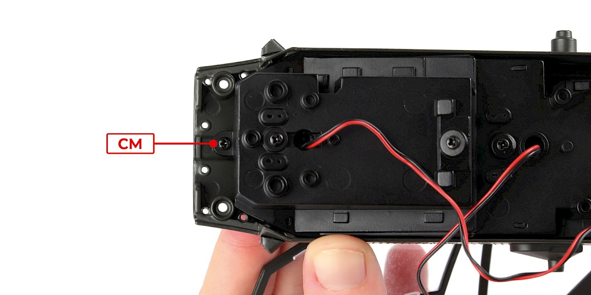
Fit the cockpit (stage 08) to the assembly.
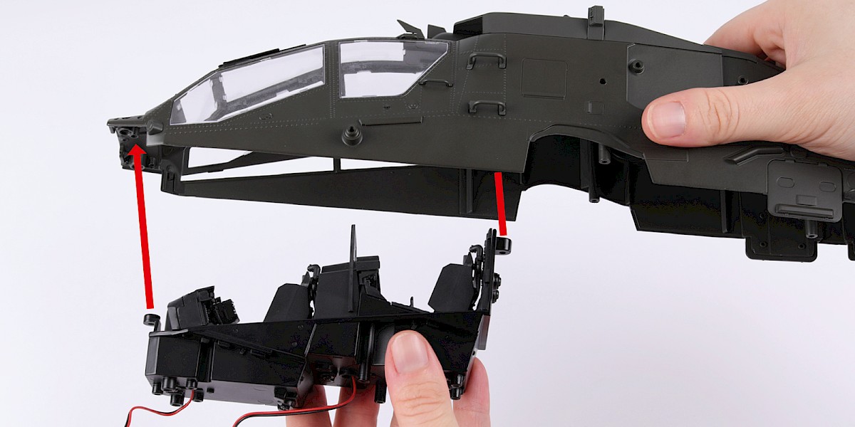
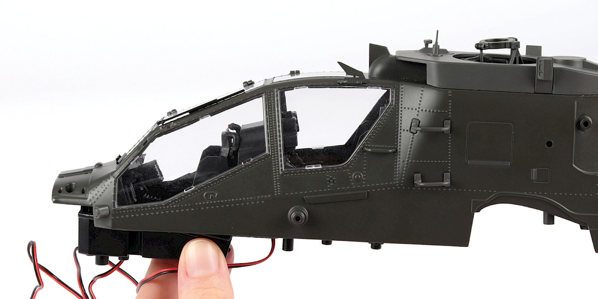
Step 5
Secure with 2x CM.


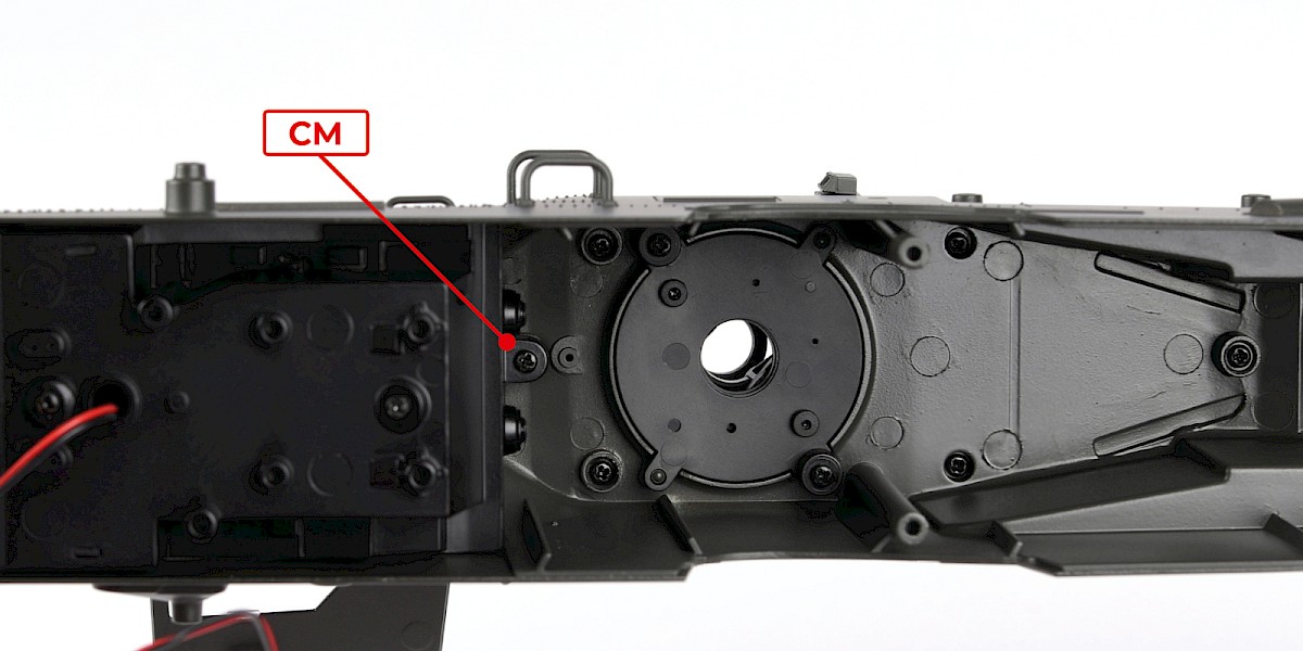
Step 6
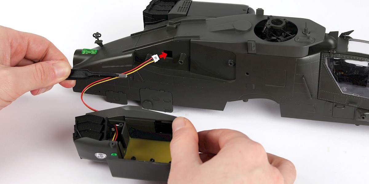
Take the left engine nacelle (stage 16) and thread the cable into the assembly.
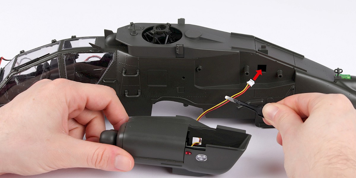
Step 7
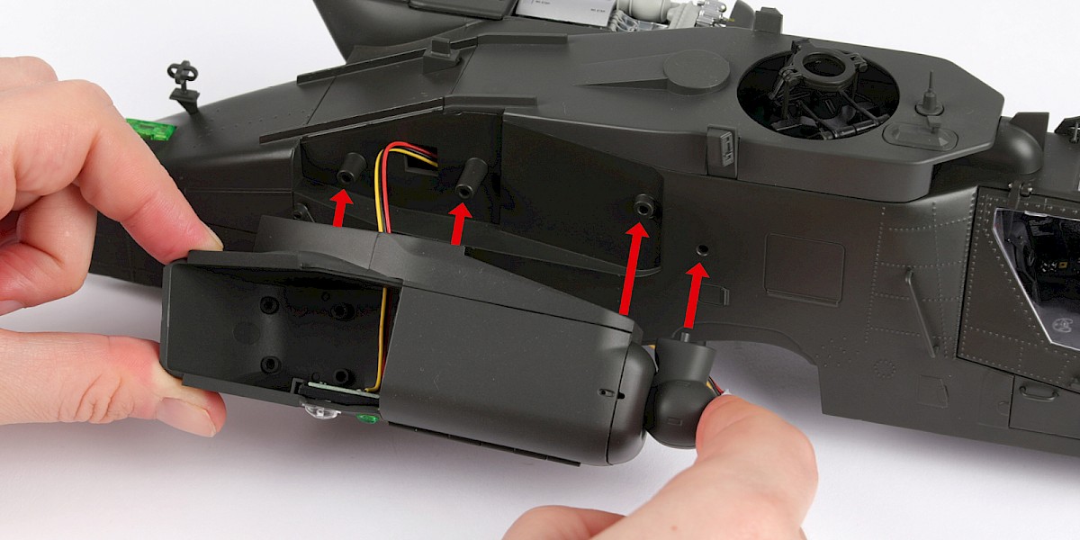
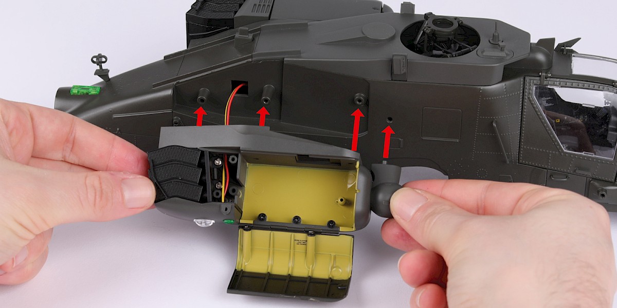
Fit the nacelle to the assembly.
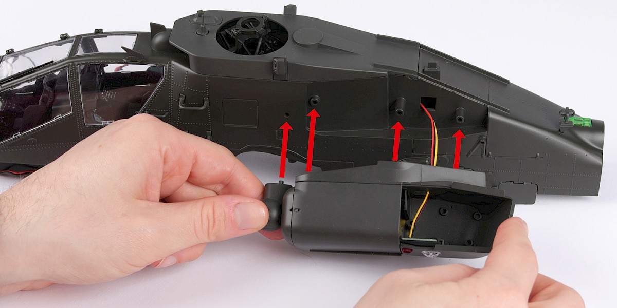
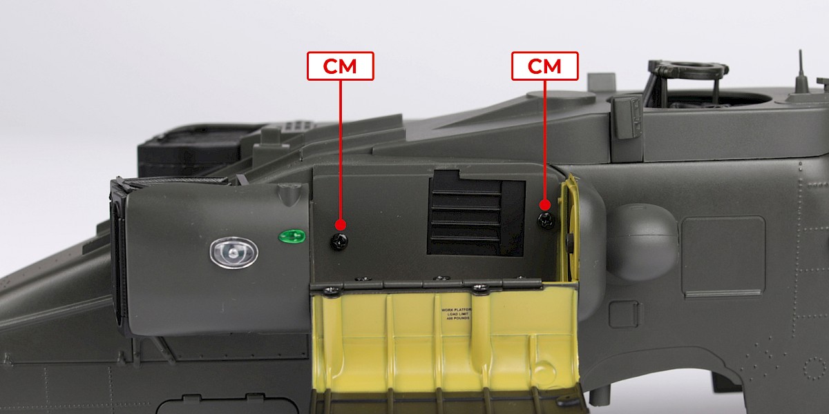
Step 8
Secure with 2x CM.
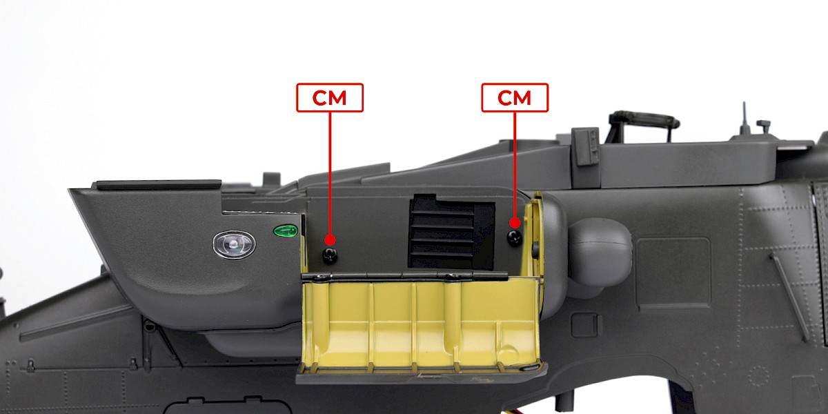
Step 9
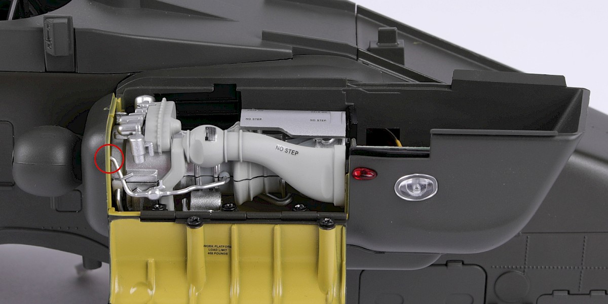
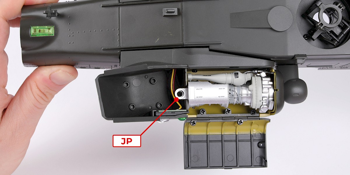
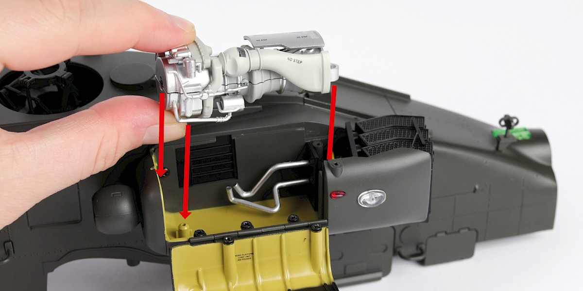
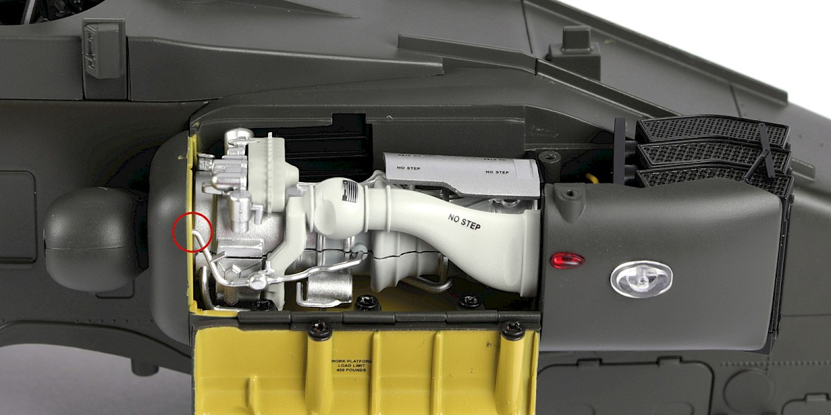
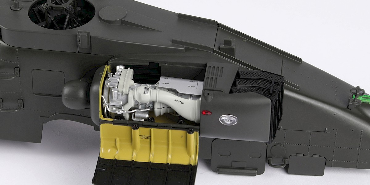
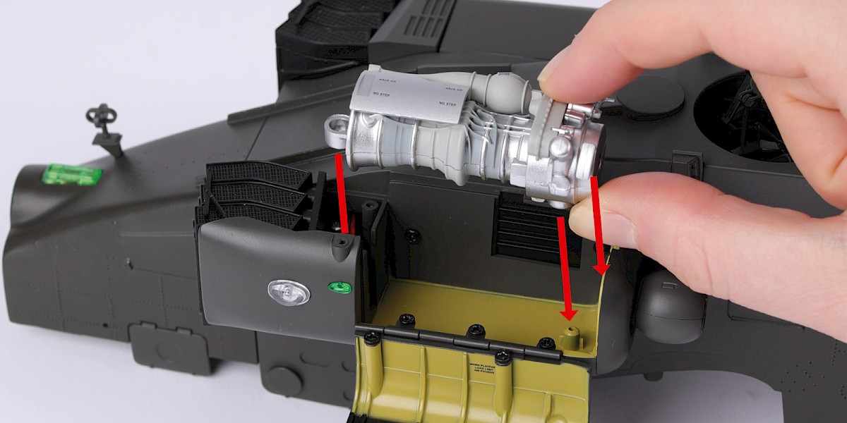
Fit the engine (stage 15) into the nacelle.
Make sure the small tube (circled) is in the correct position.
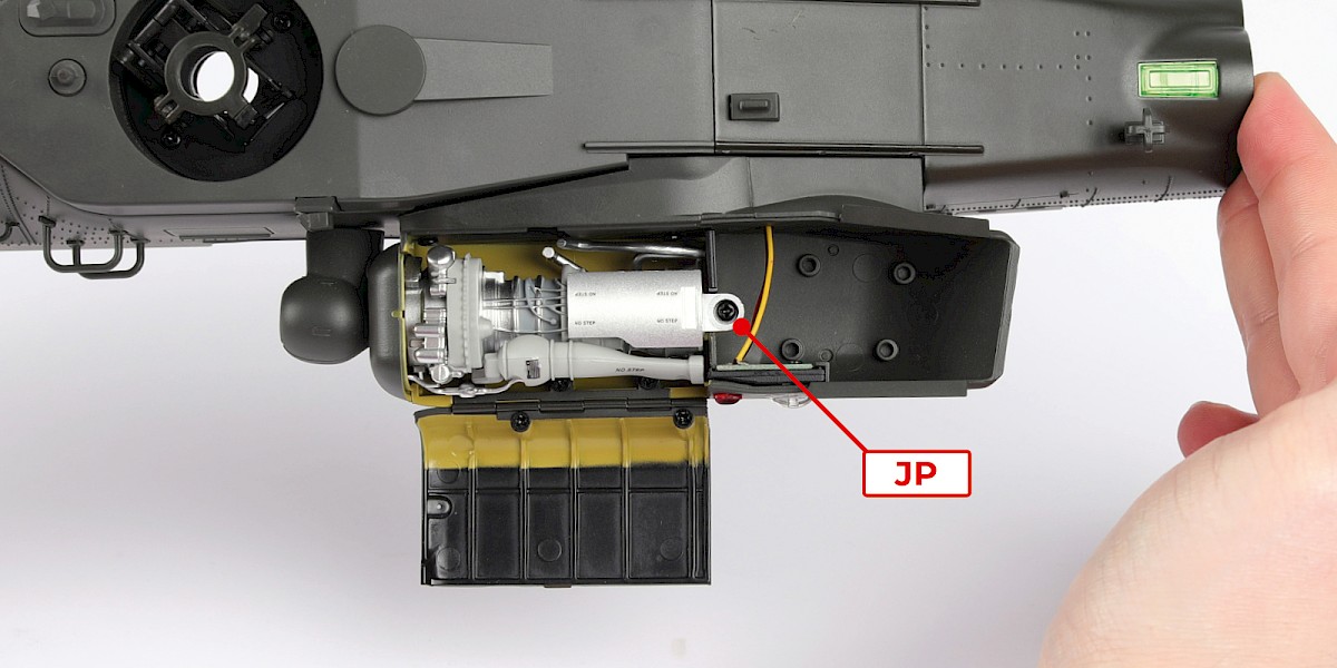
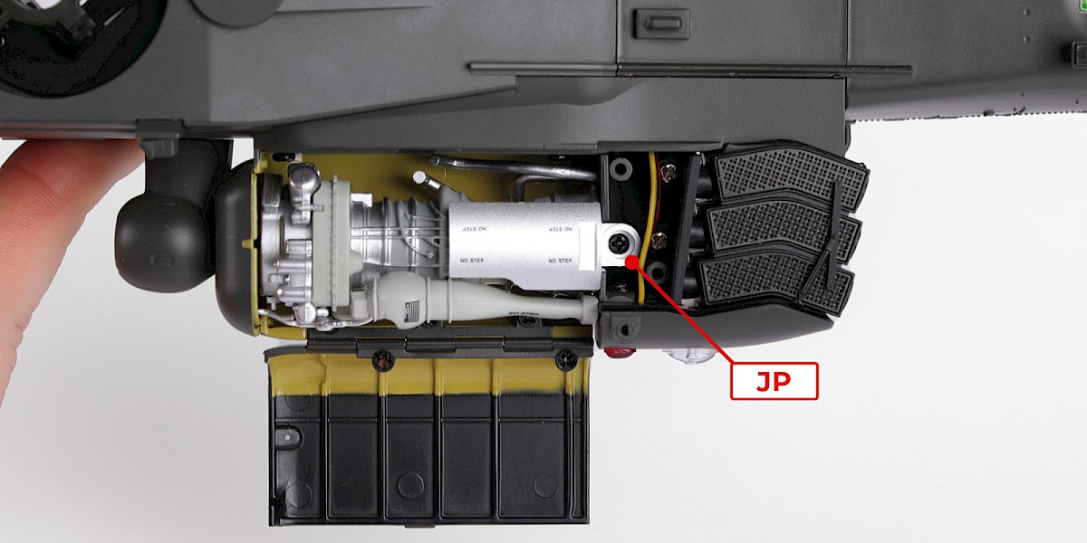
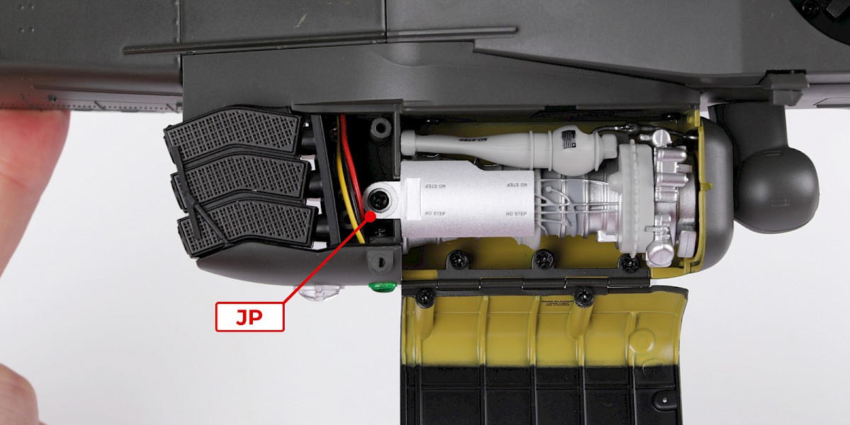
Step 10
Secure with 1x JP.
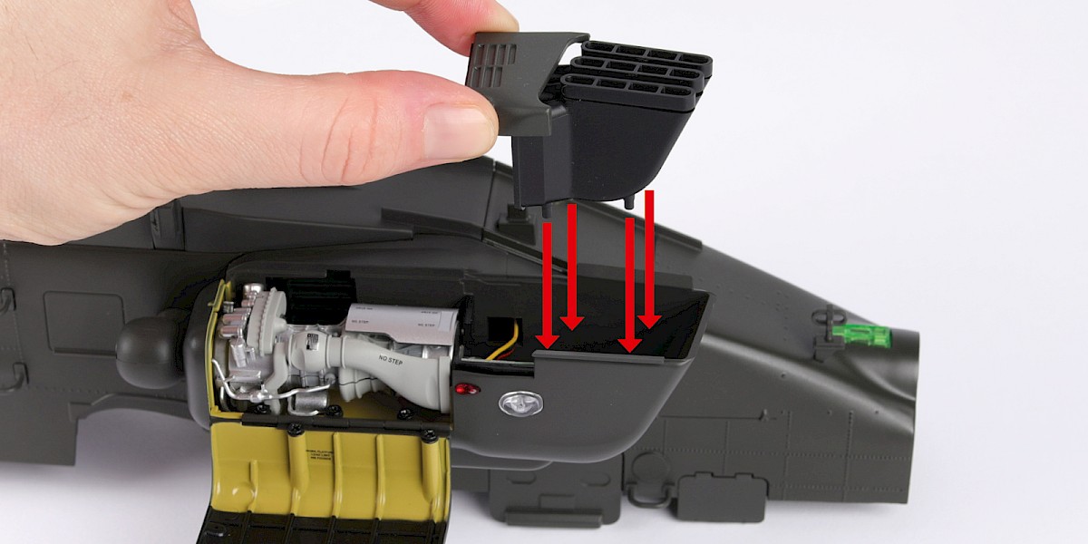
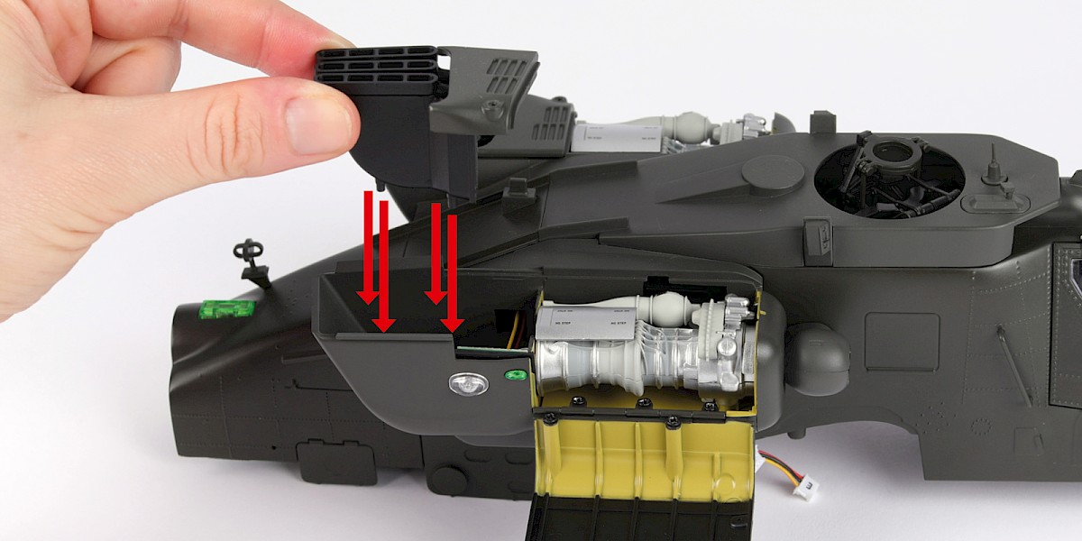
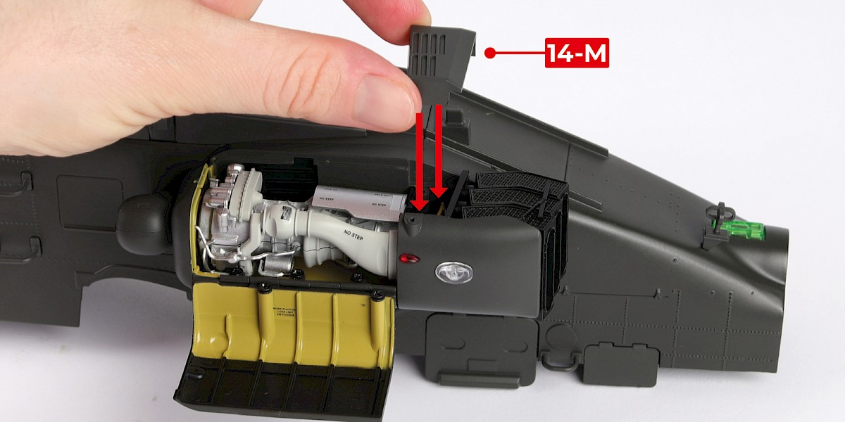
Step 11
Fit the left exhaust (stage 14) to the assembly.
Step 12
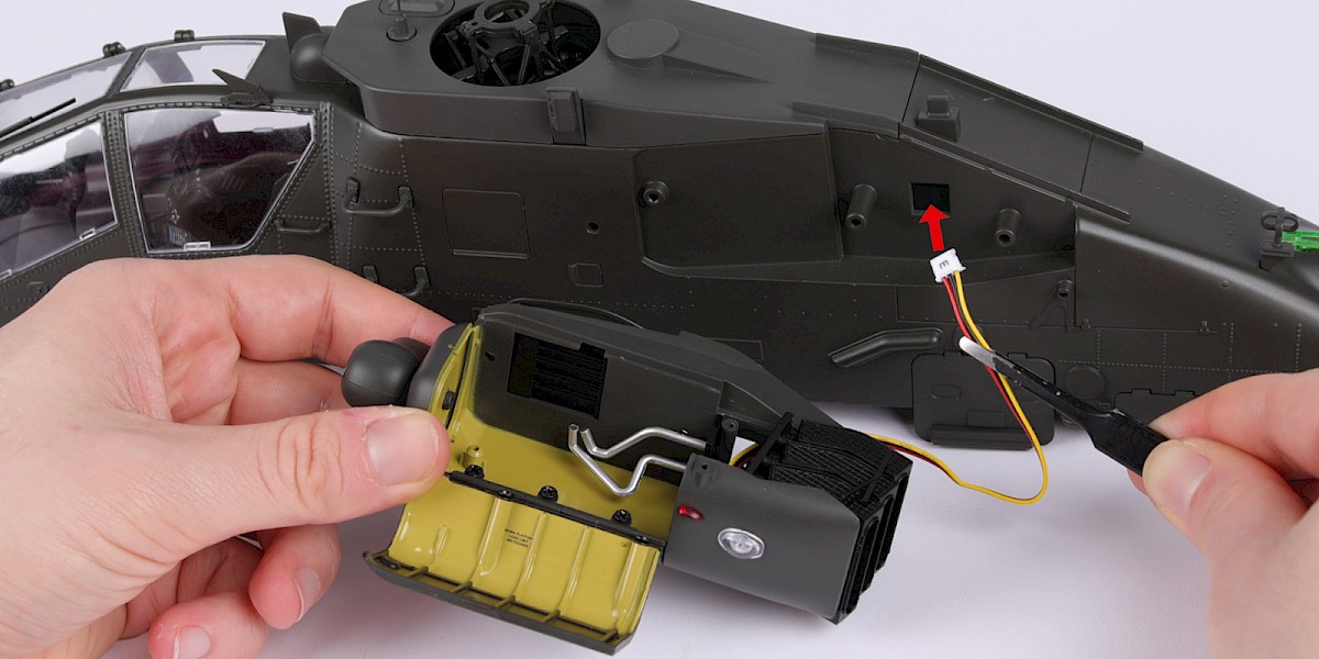
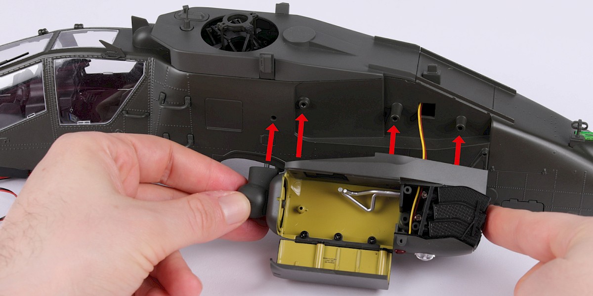
Take the right engine nacelle (stage 60) and thread the cable into the assembly.
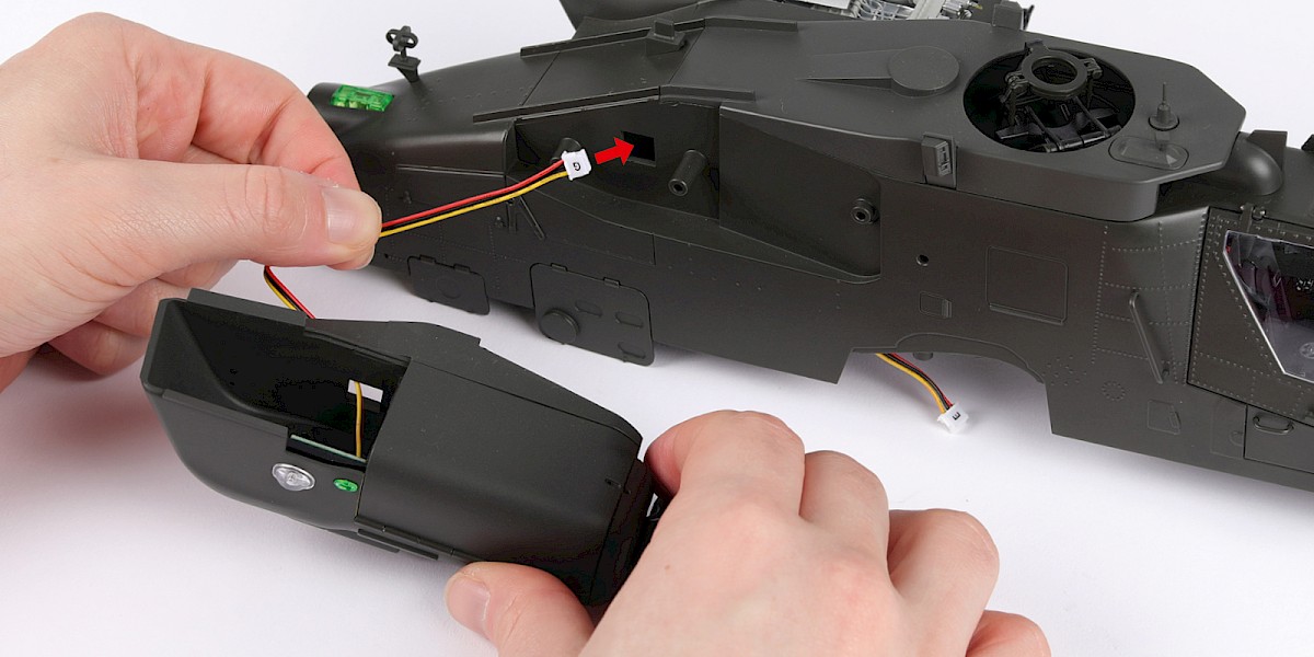
Step 13
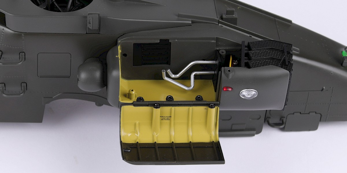
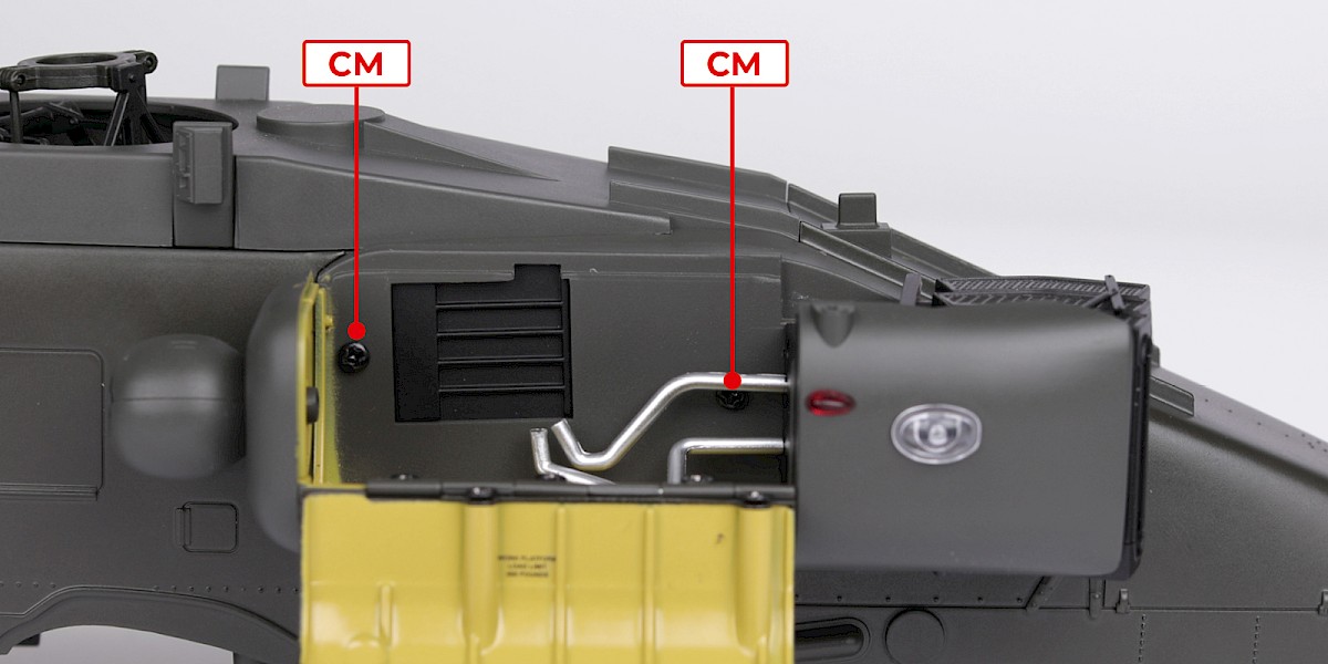
Fit the nacelle to the assembly.
Secure with 2x CM.
Step 14
Fit the engine (stage 23) into the nacelle.
Secure with 1x JP.
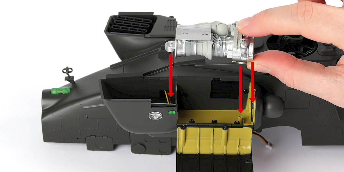
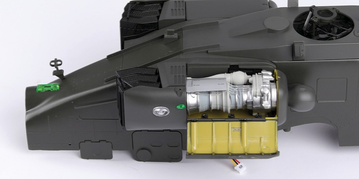
Step 15
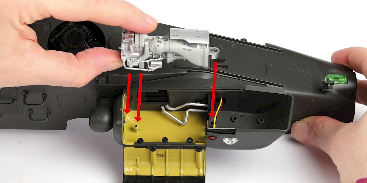
Fit the right exhaust (stage 21) to the assembly.
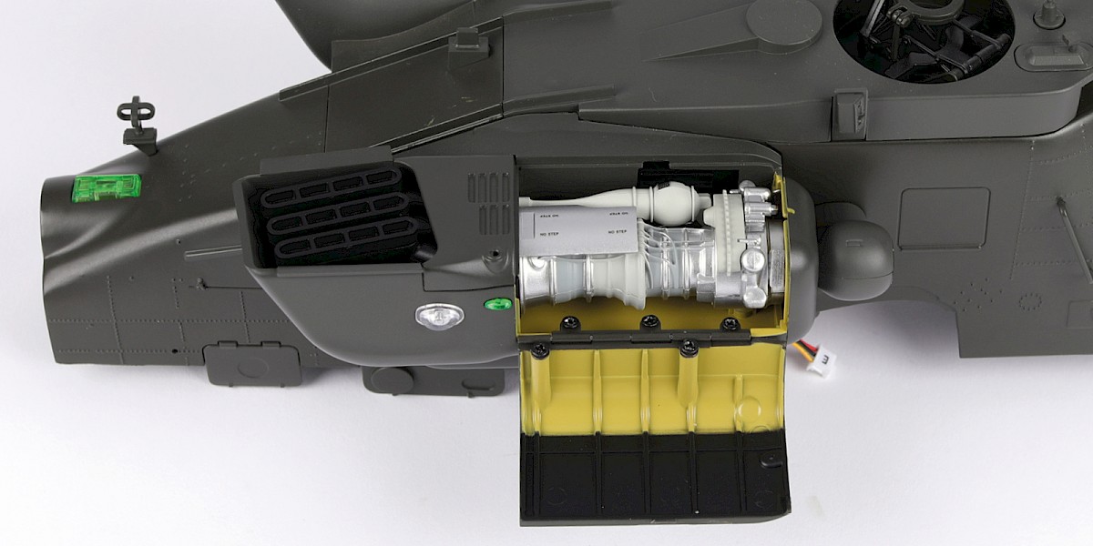
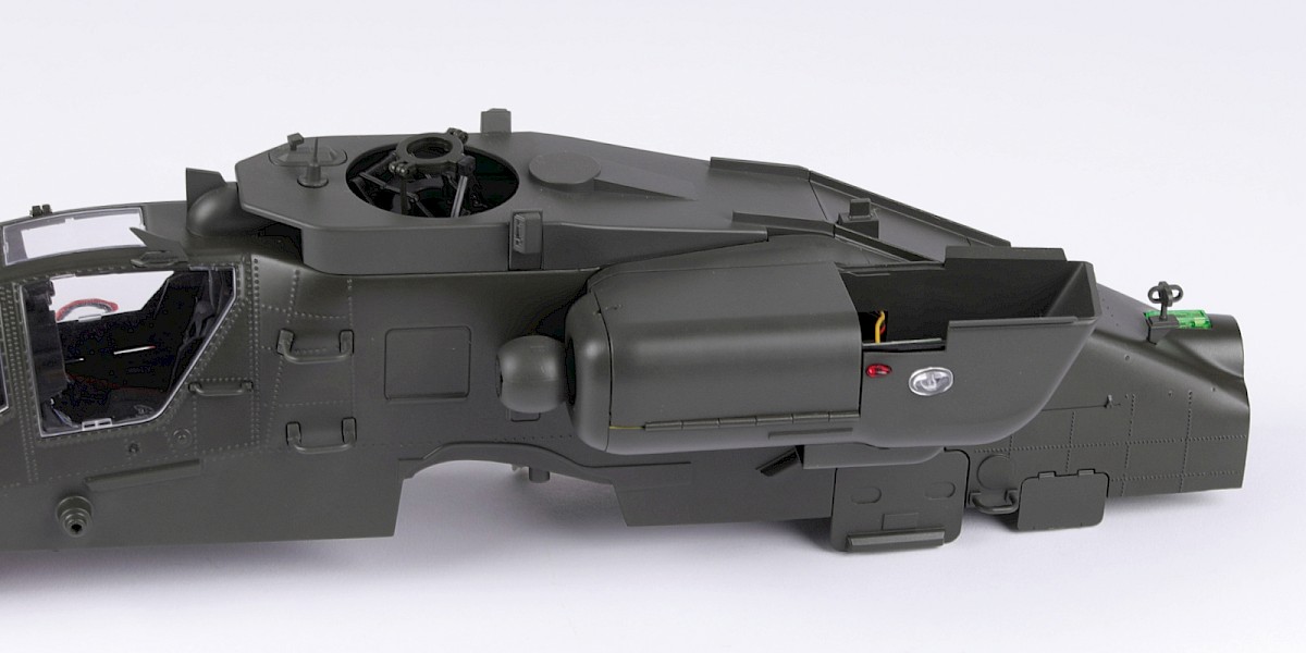
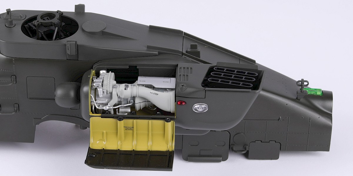
Step 16
Close the engine nacelle doors.
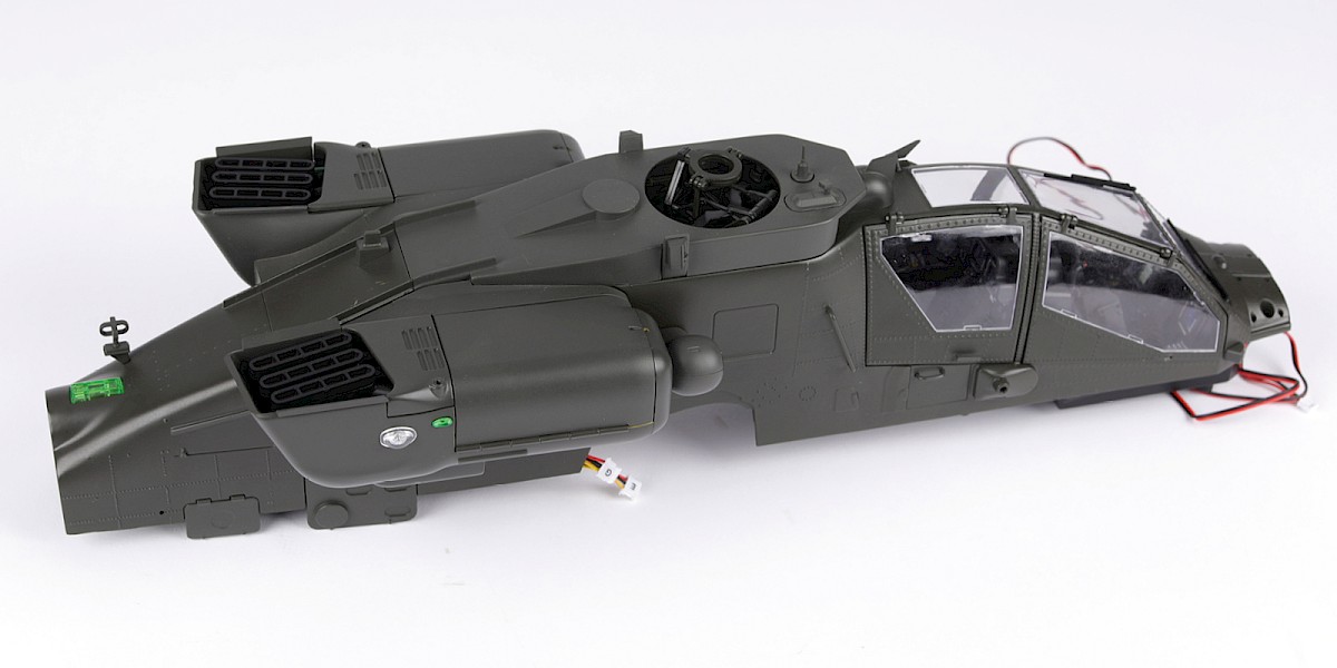
Step 17
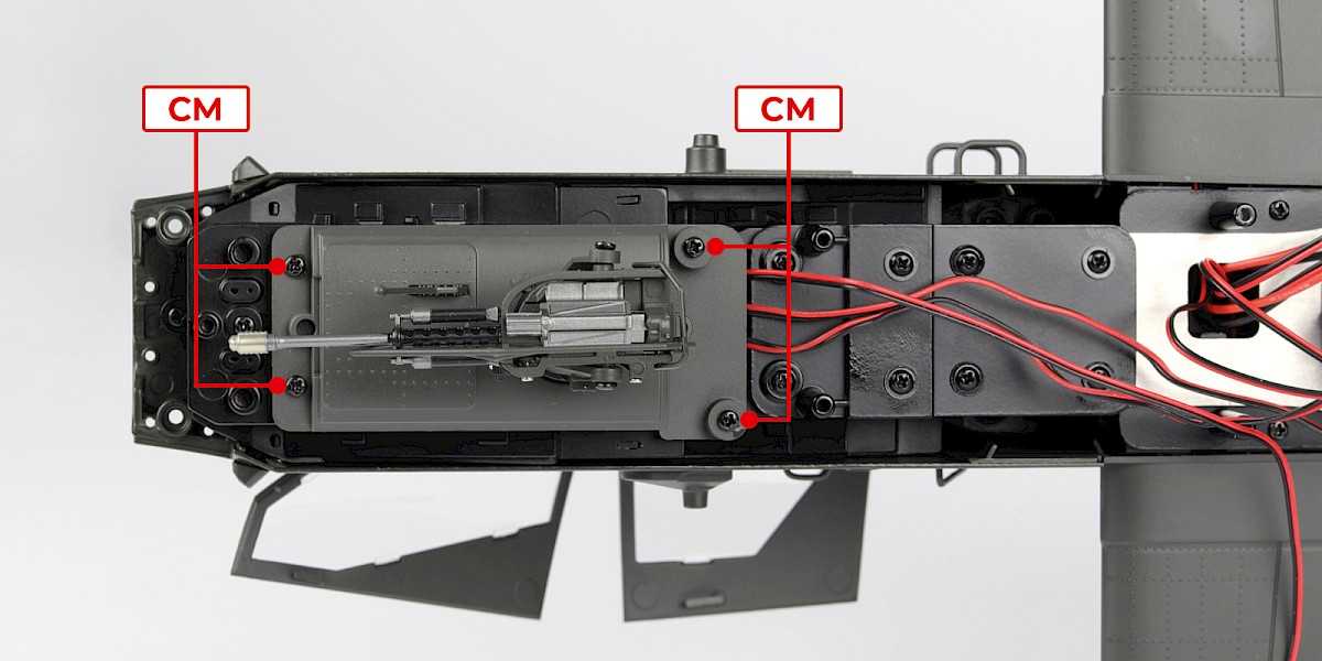
Fit the assembly to the main frame.

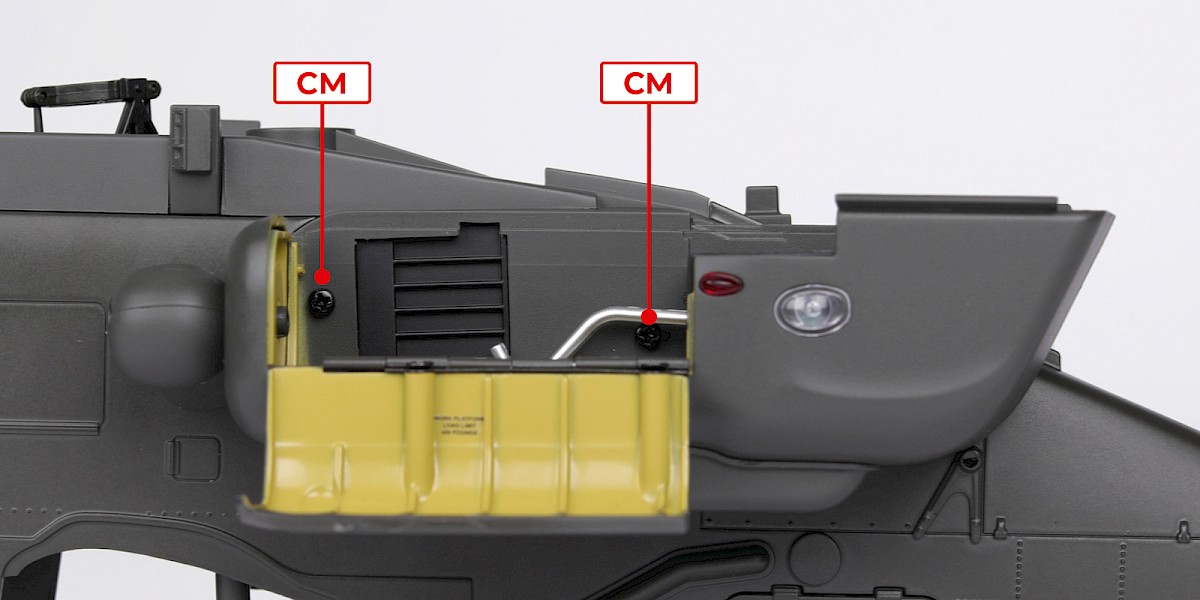
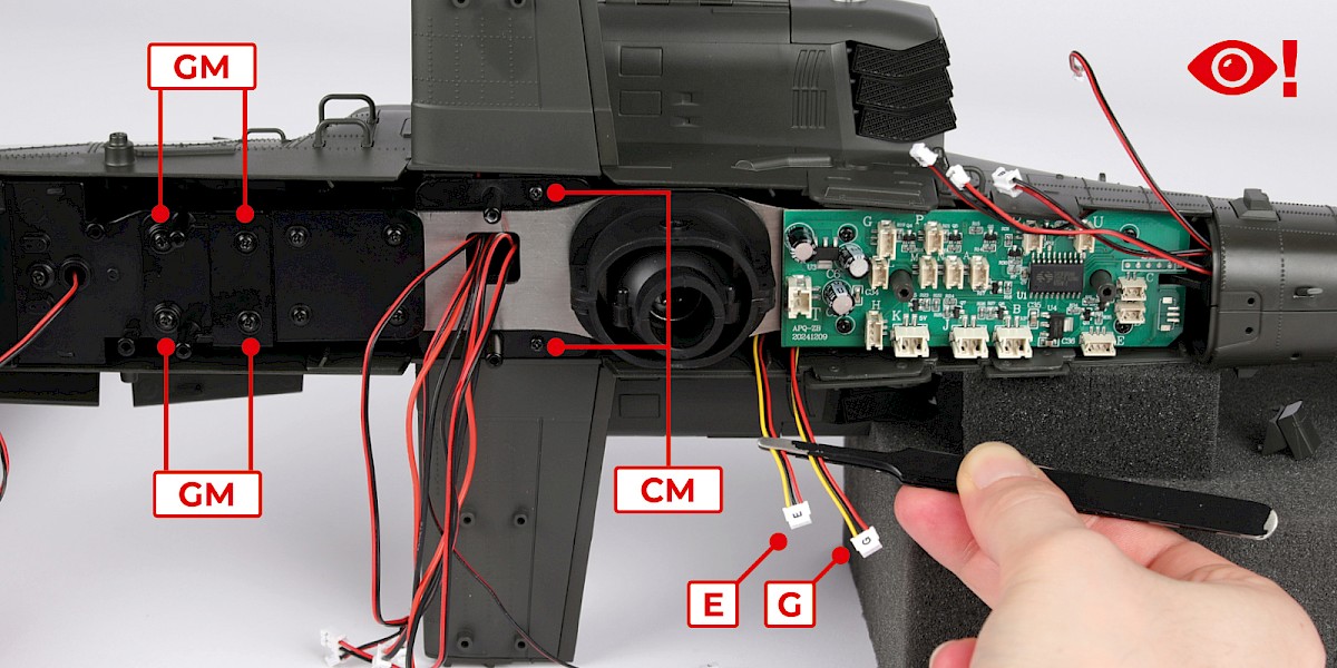
Step 18
Secure with 2x CM and 4x GM. We recommend screwing the CM screws first.
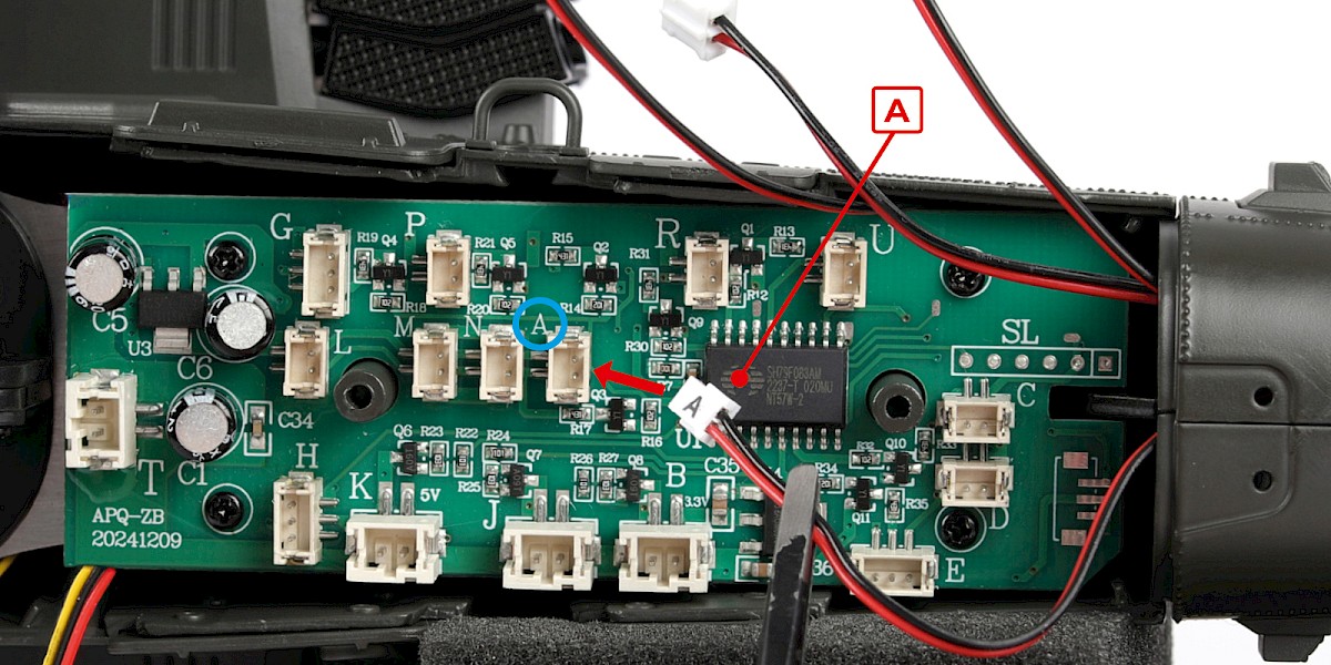
Make sure the cables "E" and "G" are positioned as shown.
Step 19
Plug the cable marked "A" into the socket marked "A".
Note: Test the cables by plugging them into the tester (2-V) before fitting them to the circuit board.

Step 20
Plug cables B, C, D, E, G, J, K, L, M, N, P, T and U into their corresponding sockets.
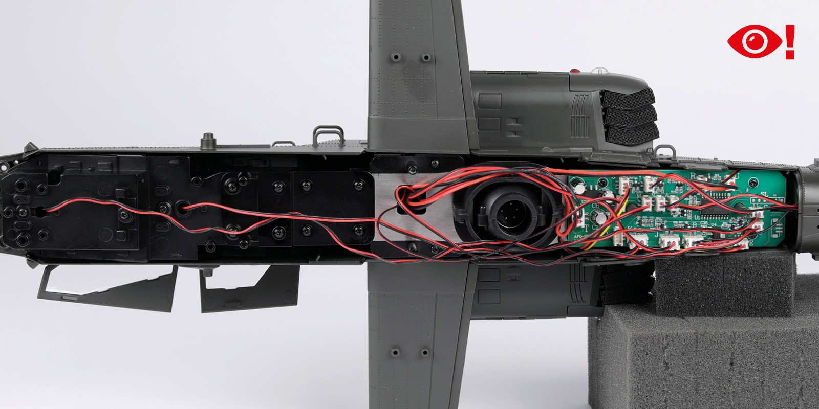
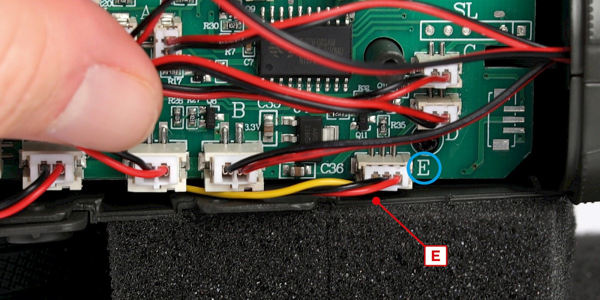
Step 21
Take care with cable E, you will need to position it between the circuit board and the fuselage as shown.
Step 22
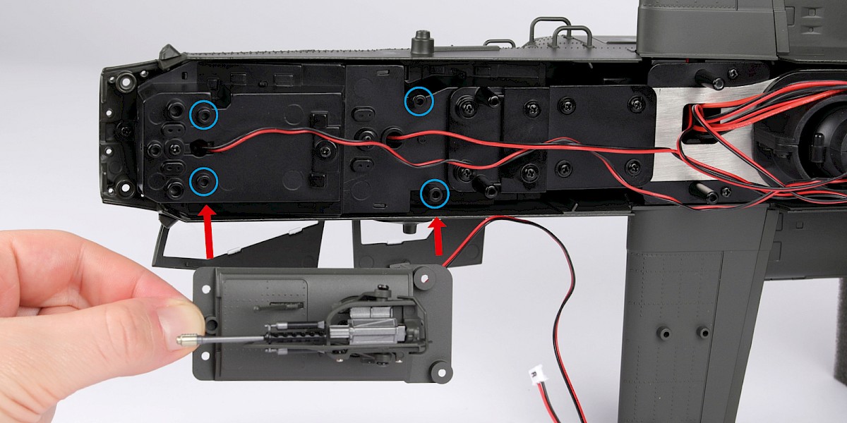
Fit the M230 chain gun (stage 61) to the assembly.
Secure with 4x CM.


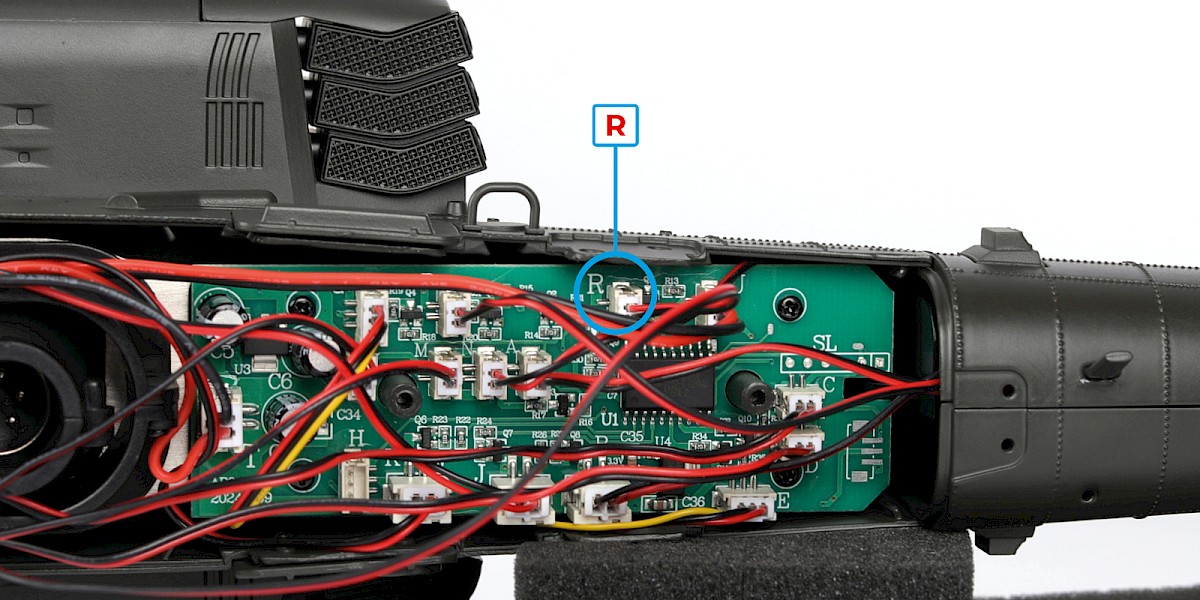
Step 23
Plug the M230 chain gun cable (marked "R") into the corresponding socket.
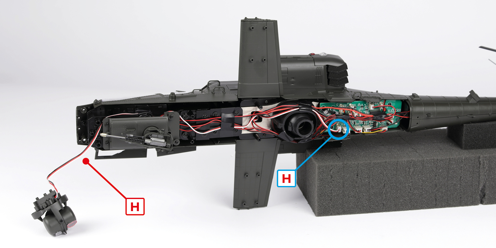
Step 24
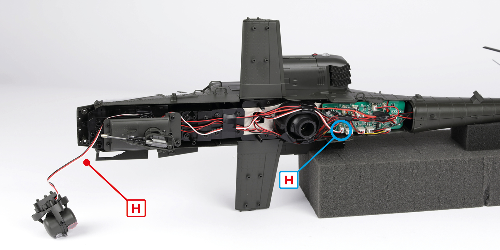
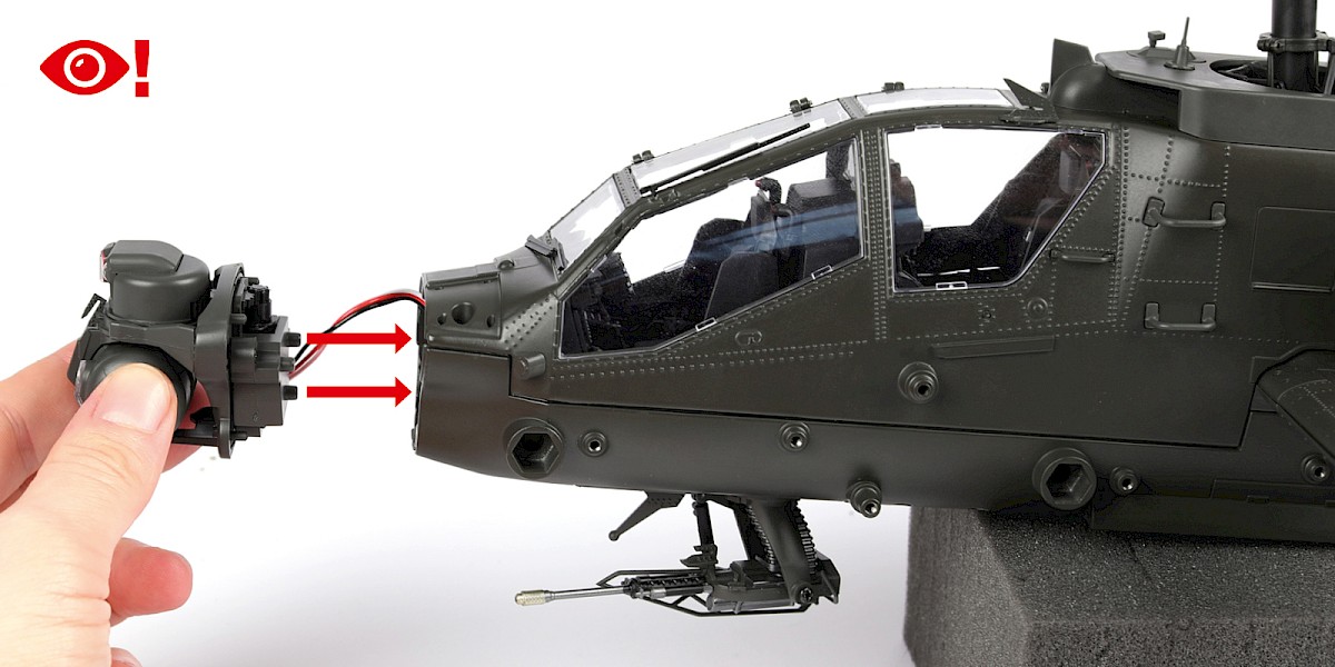
Take the M-TADS turret (stage 71) and plug the cable (marked "H") into the corresponding socket.
We recommend using tape to secure the cables as shown.
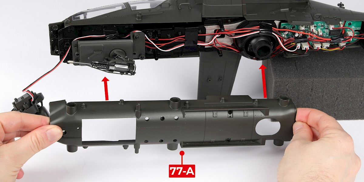
Step 25
Align 77-A with the assembly.
Start to fit 77-A by placing it carefully around the M230 chain gun.


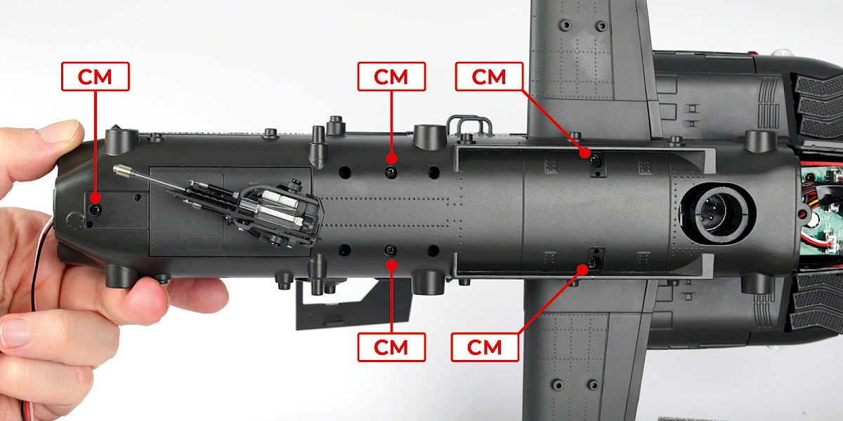
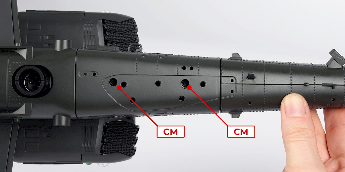
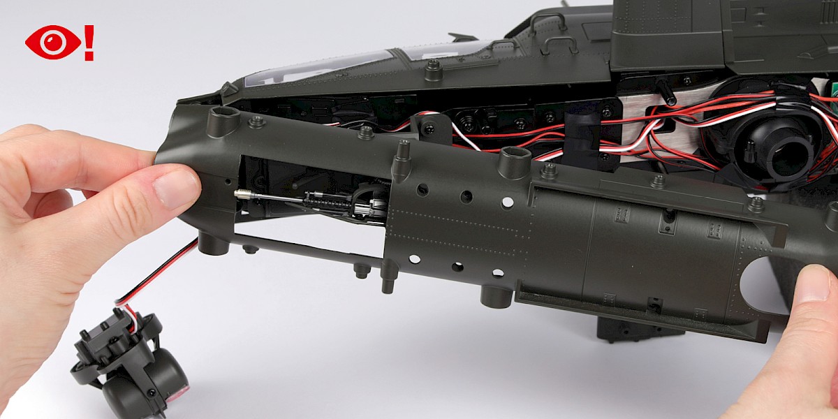
Step 26
Continue to fit 77-A in place, then secure with 5x CM.
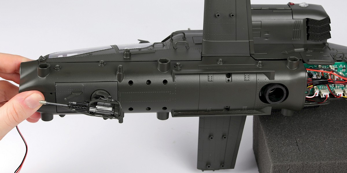
Step 27
Fit the M-TADS turret to the assembly. Make sure to push the cable inside the frame as you fit the part.

Step 28
Secure with 2x CM.
Note: Test cable H by plugging it into the tester (2-V) before fitting the last part of the fuselage.
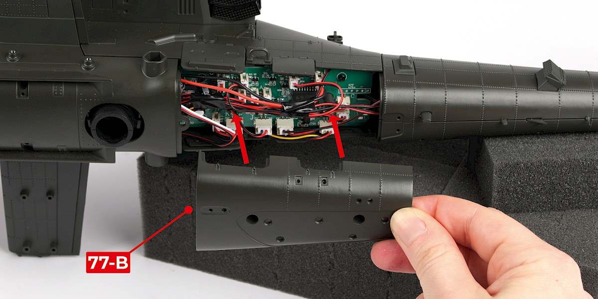
Step 29
Fit 77-B to the assembly. Make sure none of the cables are covering the screw posts.
Secure with 2x CM.
STAGE COMPLETE
In this stage you will fit the engine nacelles to your model.
If you chose to build the modified upward-facing exhaust (Version 1), follow Stage 77-v1.
If you chose to build the original exhaust (Version 2), follow this stage.
PARTS LIST
| 77-A | GM x5 |
| 77-B | JP x3 |
| CM x22 | KP x8 |

Step 1
Fit the lower swash plate (stage 34) to the fuselage assembly.
Secure with 2x KP.


Step 2
Fit the top of the fuselage (stage 35) to the assembly.


Step 3
Secure from underneath with 5x KP.
Step 4
Fit the cockpit (stage 08) to the assembly.


Step 5
Secure with 2x CM.
Step 6
Take the left engine nacelle (stage 16) and thread the cable into the assembly.
Step 7
Fit the nacelle to the assembly.
Step 8
Secure with 2x CM.
Step 9
Fit the engine (stage 15) into the nacelle.
Make sure the small tube (circled) is in the correct position.
Step 10
Secure with 1x JP.
Step 11
Fit 14-M (stage 14) to the assembly.
Step 12
Take the right engine nacelle (stage 60) and thread the cable into the assembly.
Step 13
Fit the nacelle to the assembly.
Secure with 2x CM.
Step 14
Fit the engine (stage 23) into the nacelle.
Secure with 1x JP.
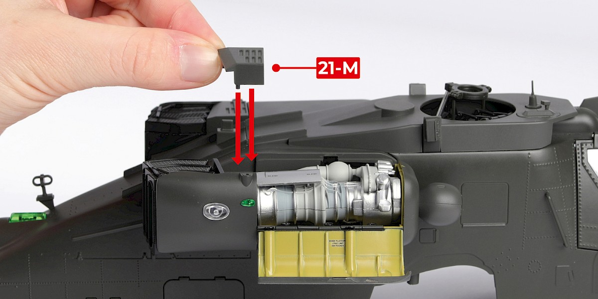
Step 15
Fit 21-M (stage 21) to the assembly.
Step 16
Close the engine nacelle doors.
Step 17
Fit the assembly to the main frame.

Step 18
Secure with 2x CM and 4x GM. We recommend screwing the CM screws first.
Make sure the cables "E" and "G" are positioned as shown.

Step 19
Plug the cable marked "A" into the socket marked "A".
Step 20
Plug cables B, C, D, E, G, J, K, L, M, N, P, T and U into their corresponding sockets.

Step 21
Take care with cable E, you will need to position it between the circuit board and the fuselage as shown.

Step 22
Fit the M230 chain gun (stage 61) to the assembly.
Secure with 4x CM.
Step 23
Plug the M230 chain gun cable (marked "R") into the corresponding socket.

Step 24
Take the M-TADS turret (stage 71) and plug the cable (marked "H") into the corresponding socket.
We recommend using tape to secure the cables as shown.
Step 25
Align 77-A with the assembly.
Start to fit 77-A by placing it carefully around the M230 chain gun.
Step 26
Continue to fit 77-A in place, then secure with 5x CM.


Step 27
Fit the M-TADS turret to the assembly. Make sure to push the cable inside the frame as you fit the part.

Step 28
Secure with 2x CM.

Step 29
Fit 77-B to the assembly. Make sure none of the cables are covering the screw posts.
Secure with 2x CM.


STAGE COMPLETE

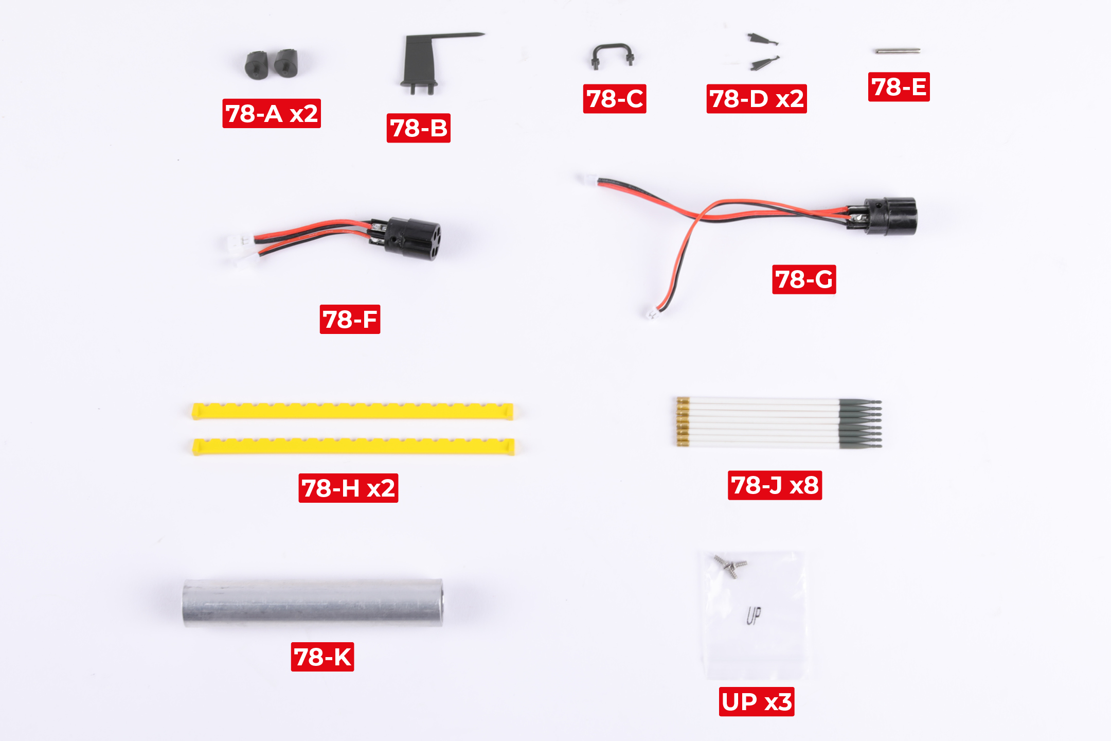
PARTS LIST
| 78-A x2 | 78-G |
| 78-B | 78-H x2 |
| 78-C | 78-J x8 |
| 78-D x2 | 78-K |
| 78-E | UP x3 |
| 78-F |
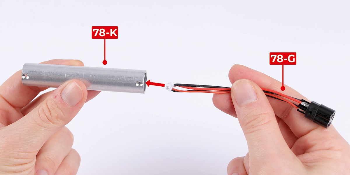
Step 1
Fit 78-G into 78-K.
Make sure to align the screw holes.
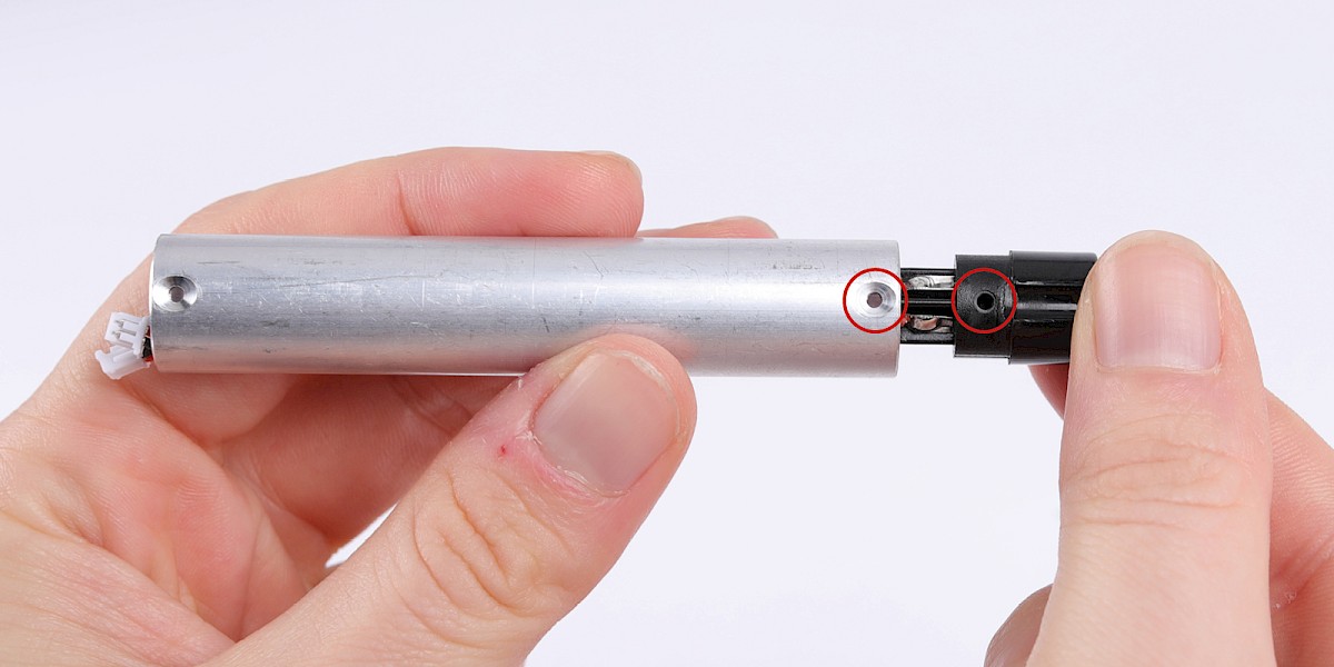
Step 2
Secure with 1x UP.
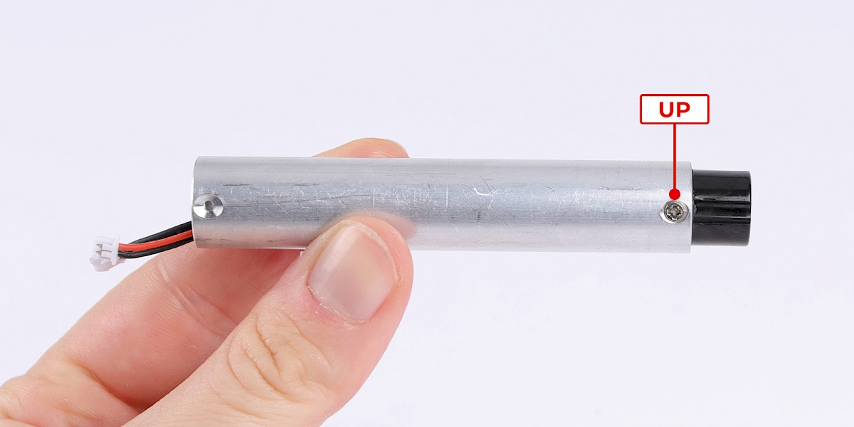
Step 3
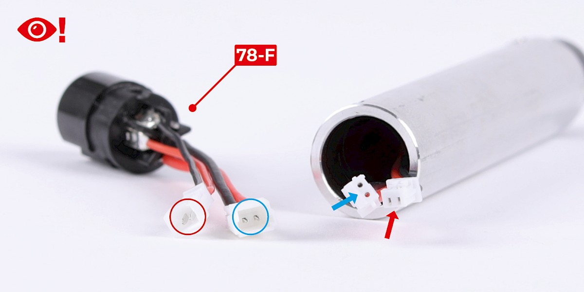
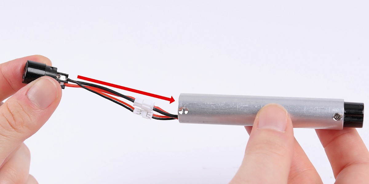
Take 78-F. Note that the pins and connectors on the cables are different shapes.
Connect the cables then fit 78-F into 78-K.
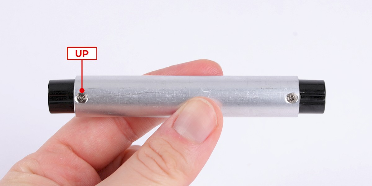
Step 4
Secure with 1x UP.
Step 5
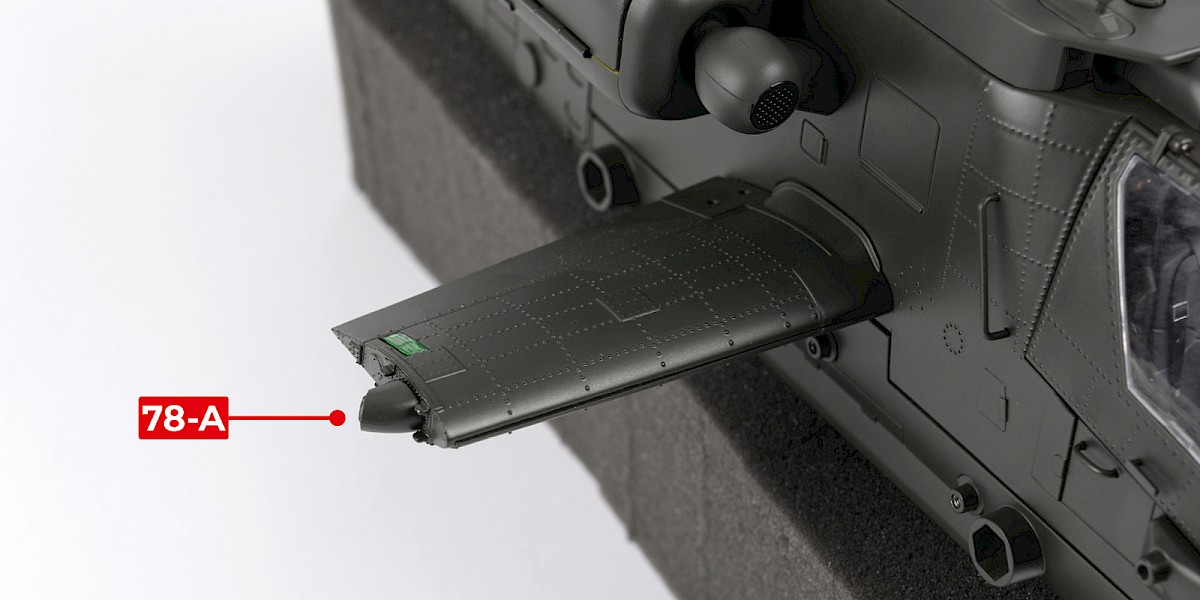
Fit 78-A to the left wing.
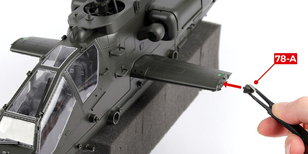
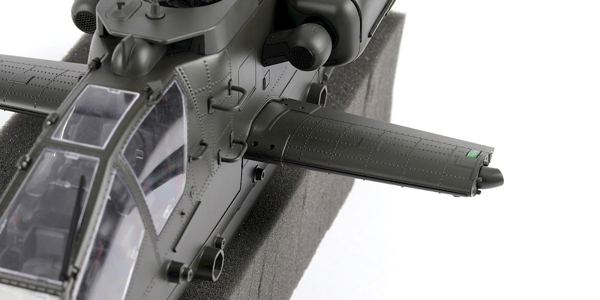
Step 6
Fit the other 78-A to the right wing.
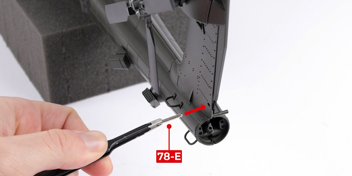
Step 7
Fit 78-E through the tail.
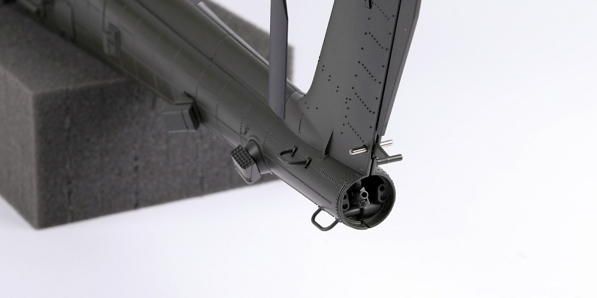
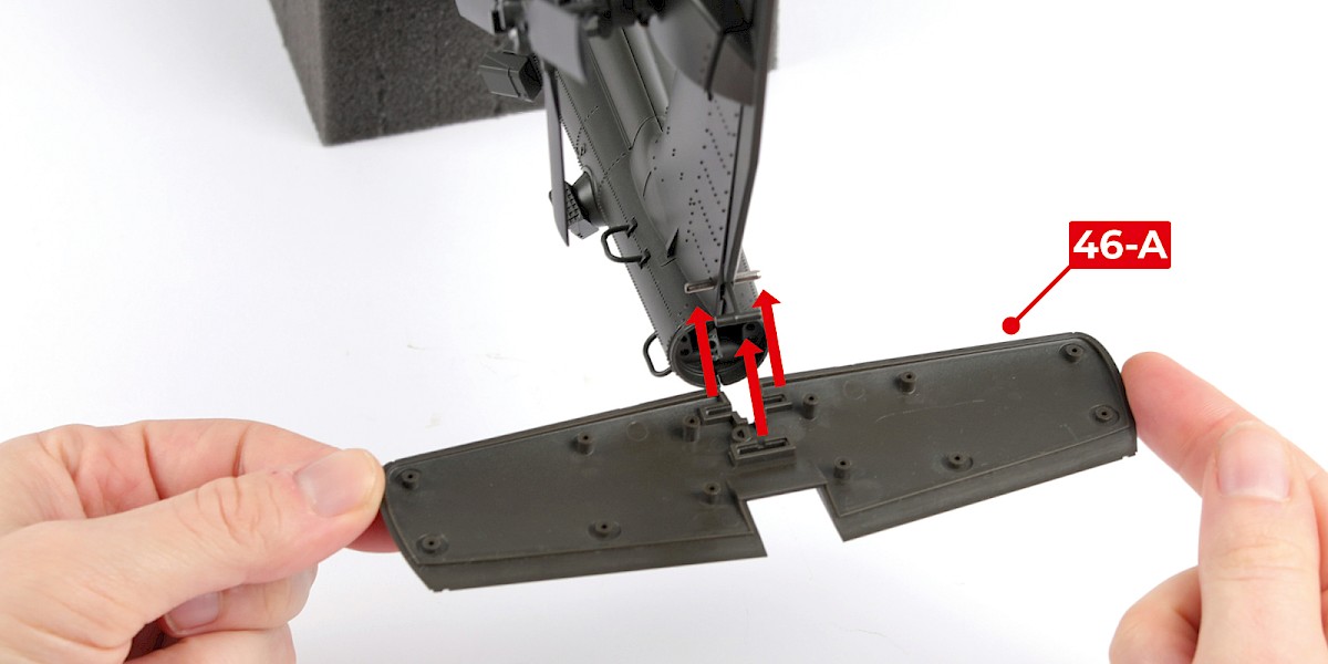
Step 8
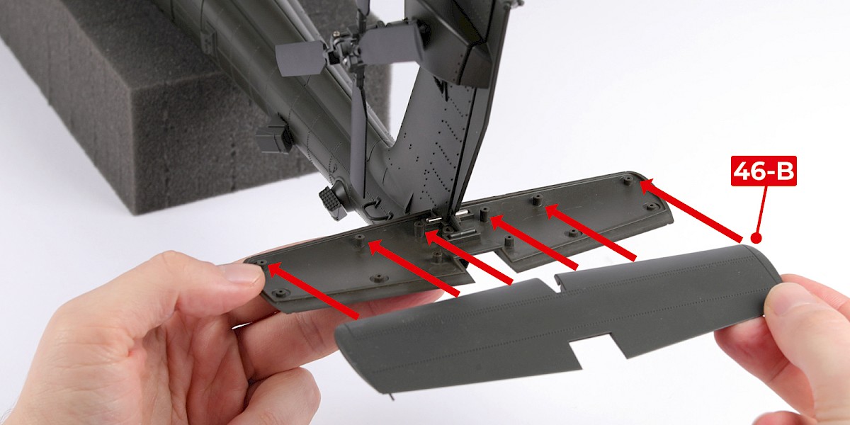
Position 46-A on the tail.
Press 46-B firmly onto 46-A. Both parts were supplied with stage 46.
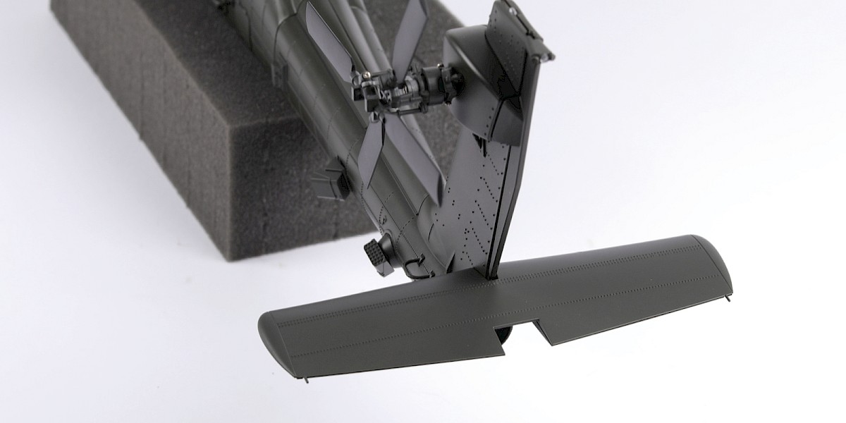
Step 9
The tail should look like this.
Step 10
You will now add the decals to a set of rockets.
Cut the decals outlined in red from 76-N.
Step 11
Take 78-J and a set of decals.
Apply decals A, B, C and D to 78-J. Use the rockets from the previous rocket assemblies as a reference when positioning the decals.
Step 12
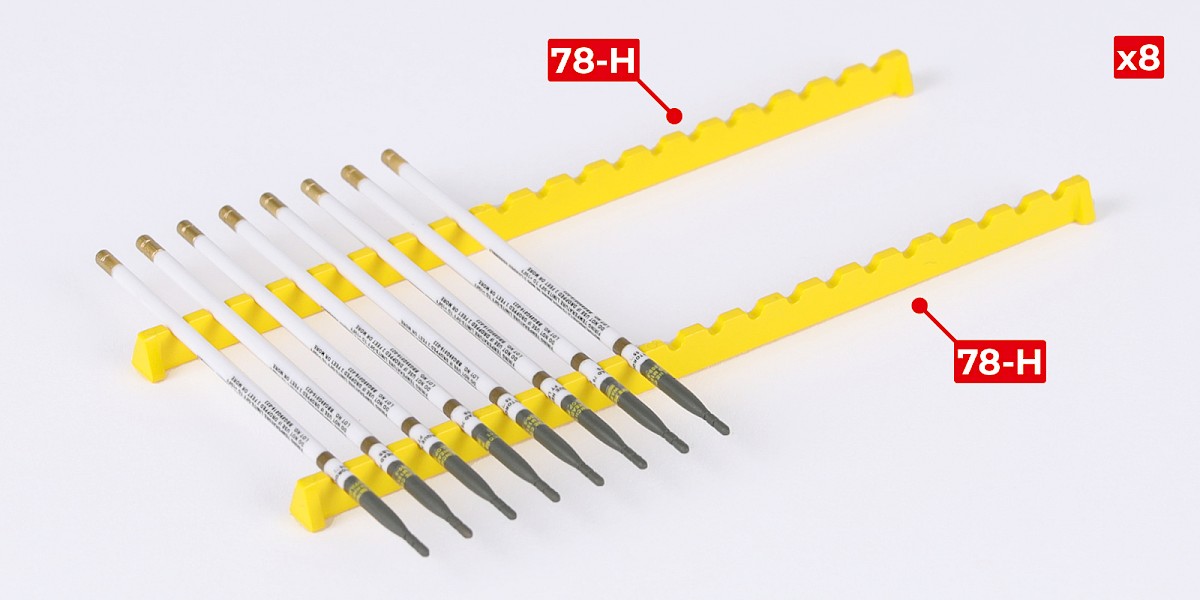
Repeat to make 8 rockets.
The rockets can be displayed on the racks – parts 78-H.
STAGE COMPLETE
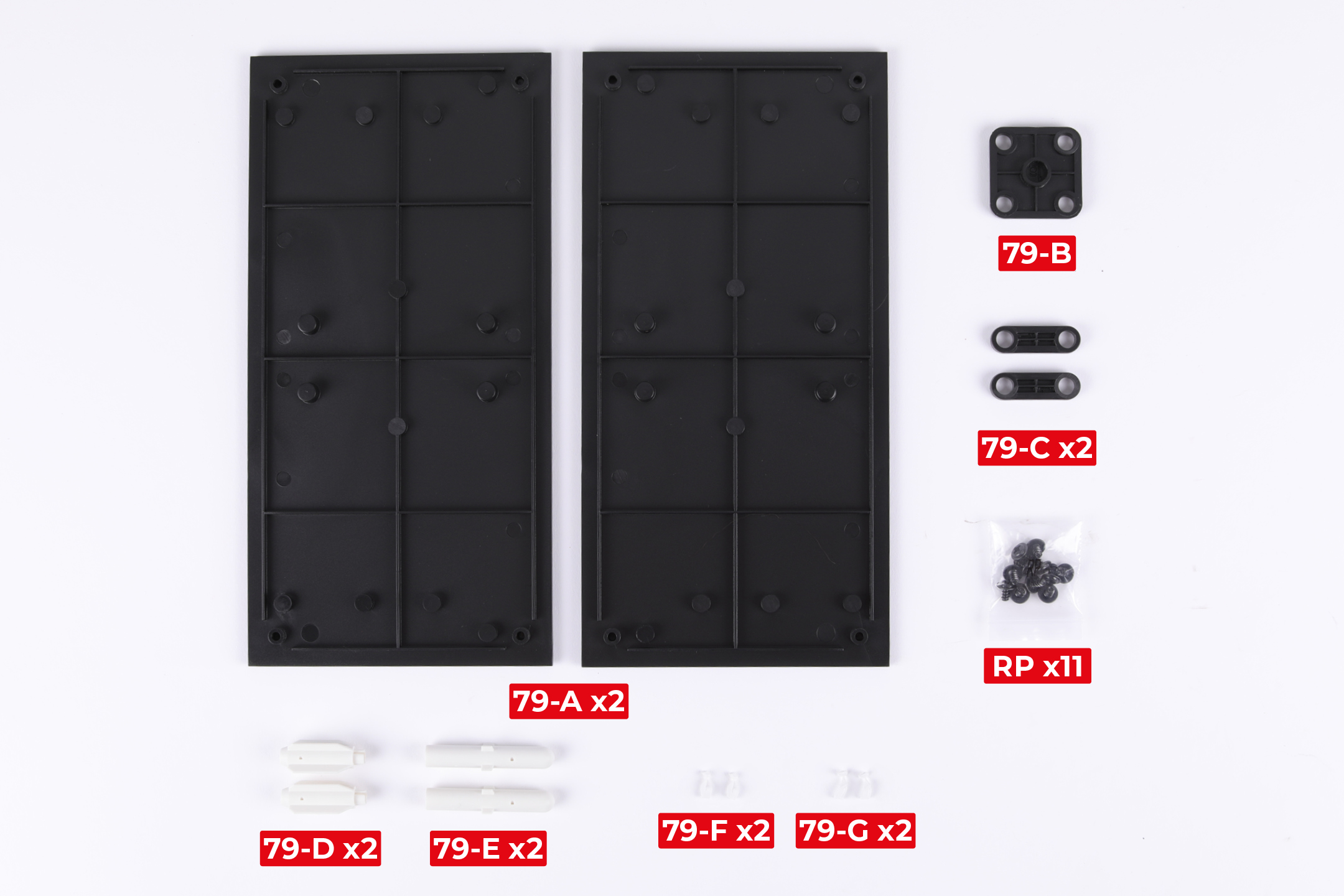
PARTS LIST
| 79-A x2 | 79-E x2 |
| 79-B | 79-F x2 |
| 79-C x2 | 79-G x2 |
| 79-D x2 | RP x11 |
Step 1
Fit both parts 79-A to the assembly from stage 72. Make sure the parts are in the orientation shown.
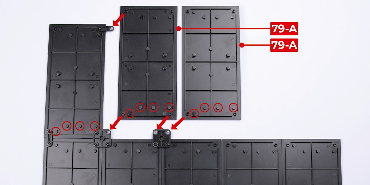
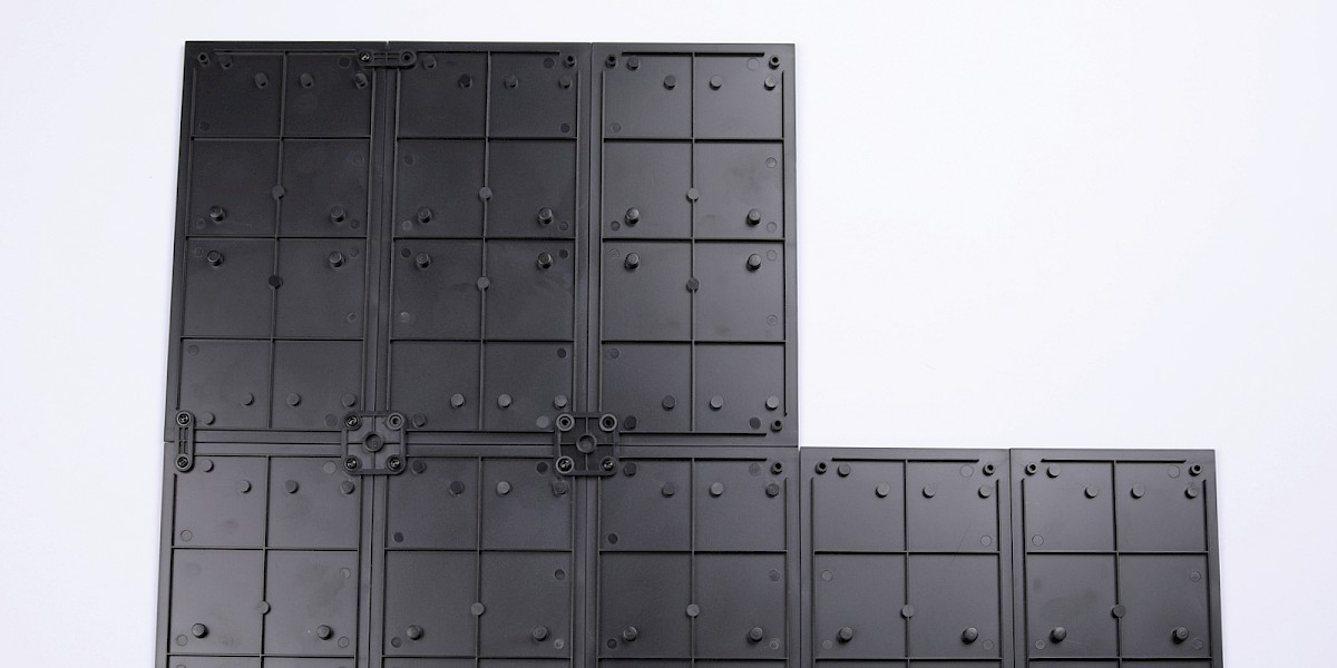
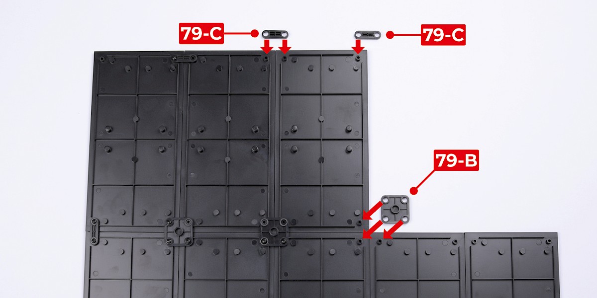
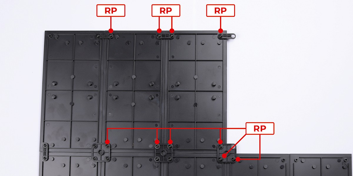
Step 2
Fit parts 79-B and 79-C as shown.
Secure with 10x RP.
Step 3
Fit 79-D to 79-E.


Step 4
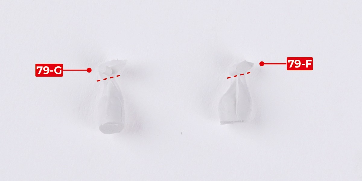
Cut parts 79-G and 79-F off the sprues.
Step 5
Glue 79-F to the assembly.

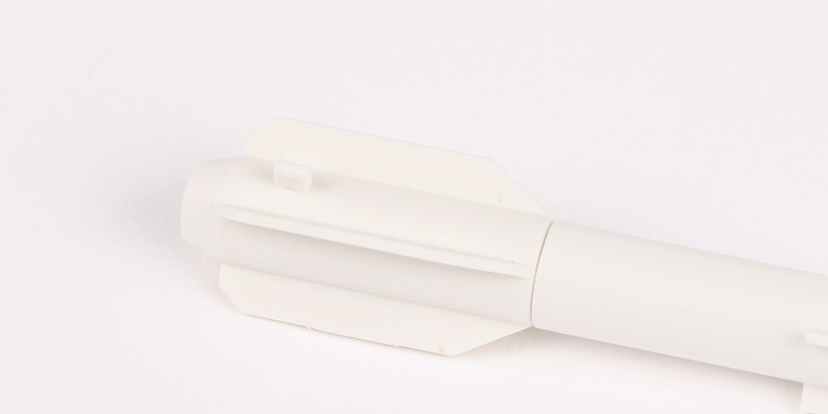
Step 6
Glue 79-G to the assembly.

Step 7
Cut the decals outlined in red from 76-N.

Step 8
Apply decals A, B, C and D to the missile.
Repeat this process to assemble two missiles.

STAGE COMPLETE
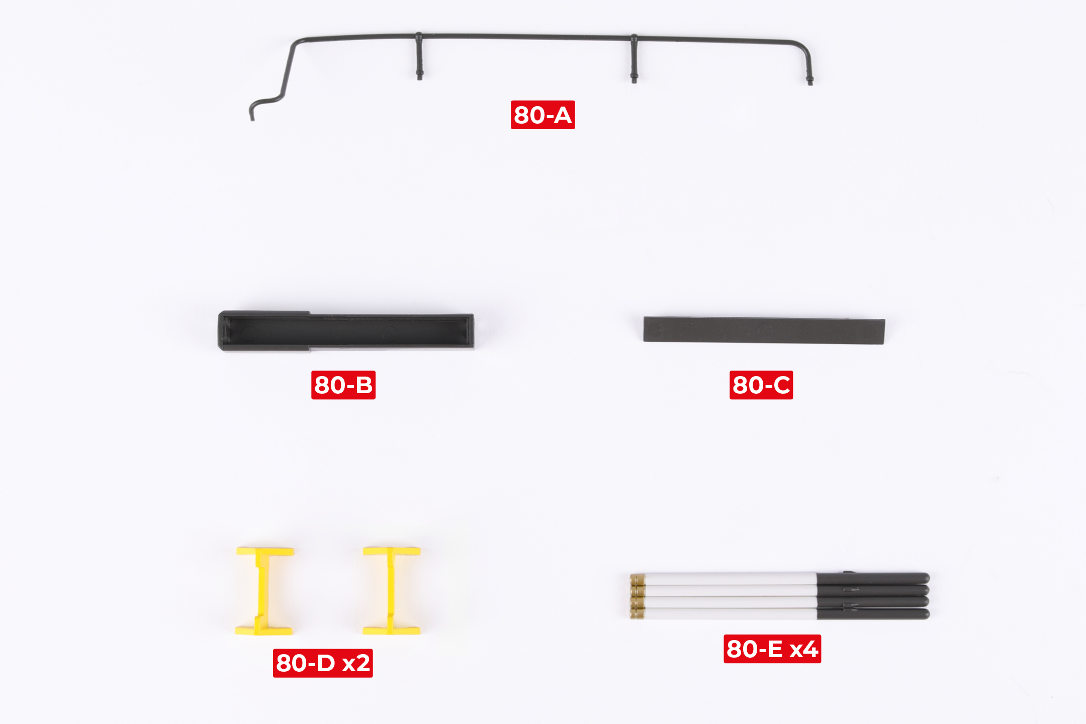
PARTS LIST
| 80-A |
| 80-B |
| 80-C |
| 80-D* x2 |
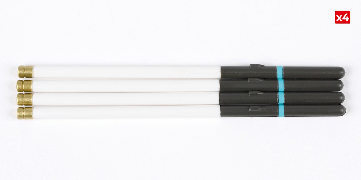
| 80-E x4 |
* These racks are for a Spike missile launcher. You will receive racks for the DAGR missile launcher in a later stage.
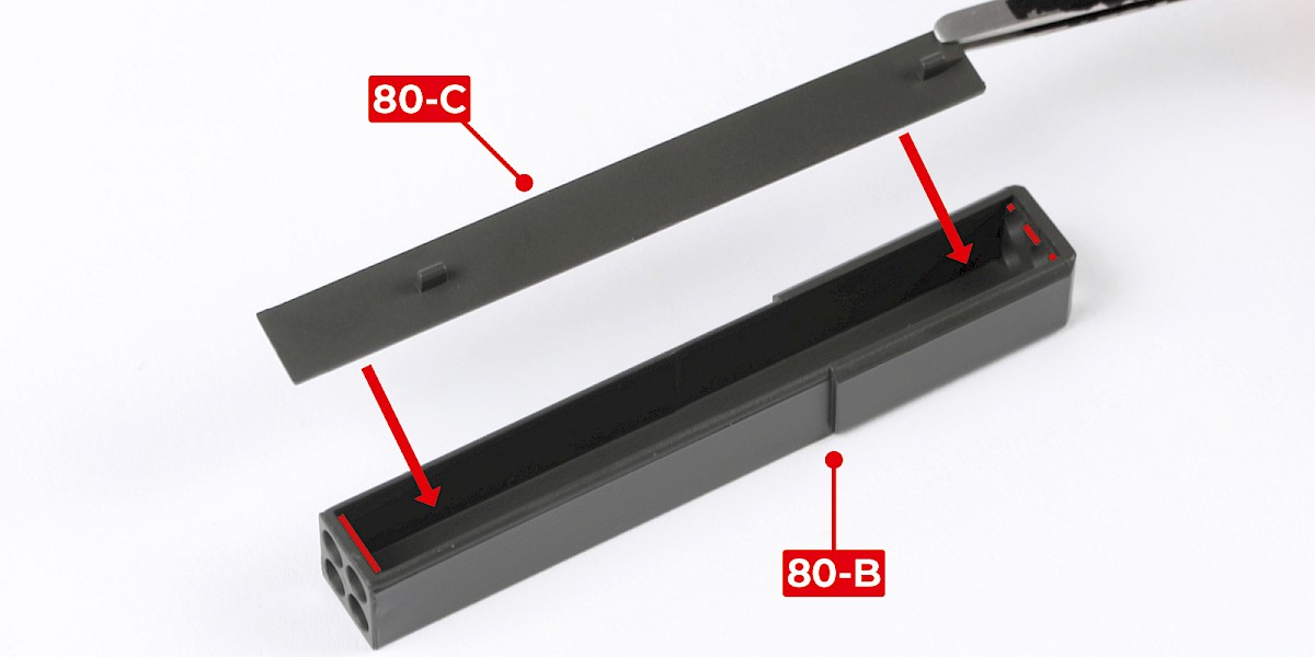
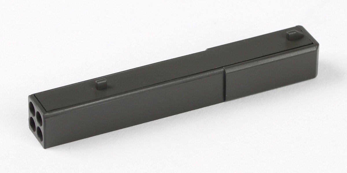
Step 1
Apply glue to 80-B as shown by the red lines.
Glue 80-C to 80-B.
Step 2
Cut the decals outlined in red from 76-N.
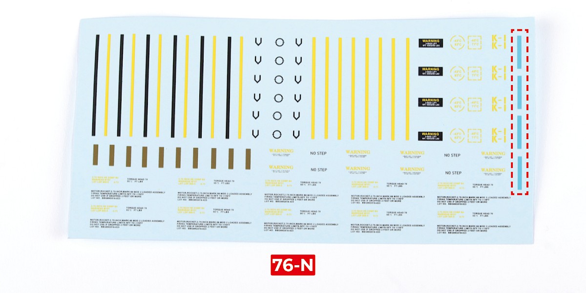
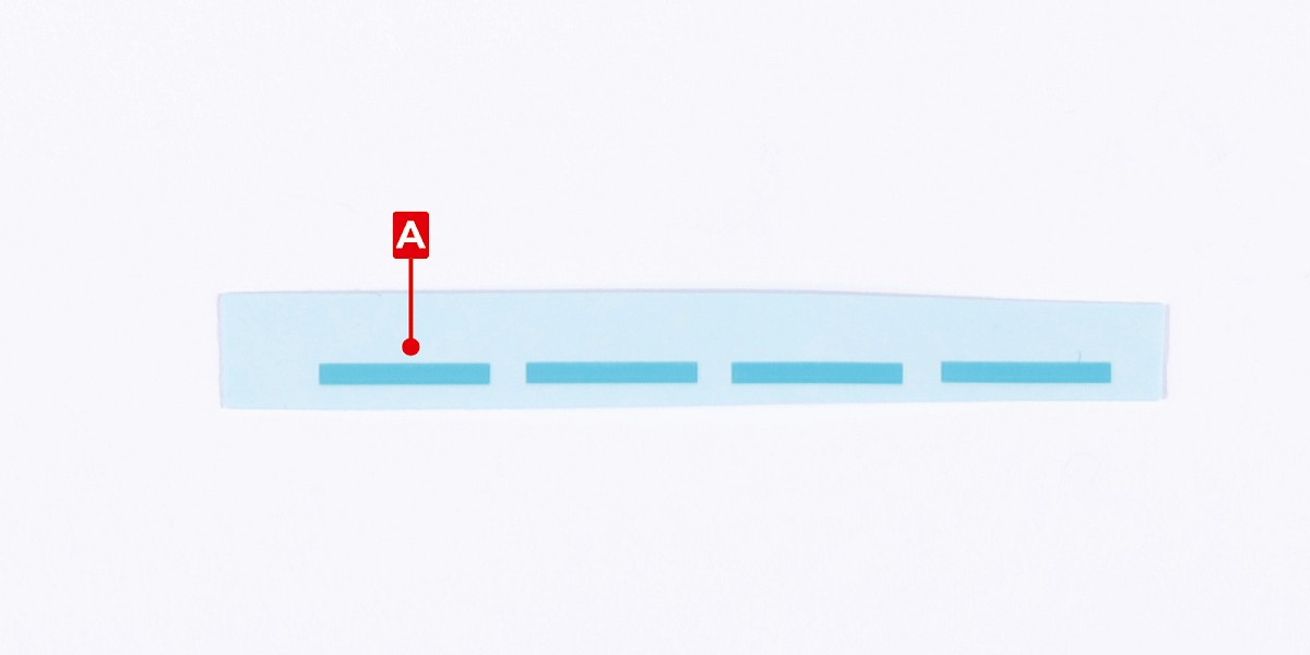
Step 3
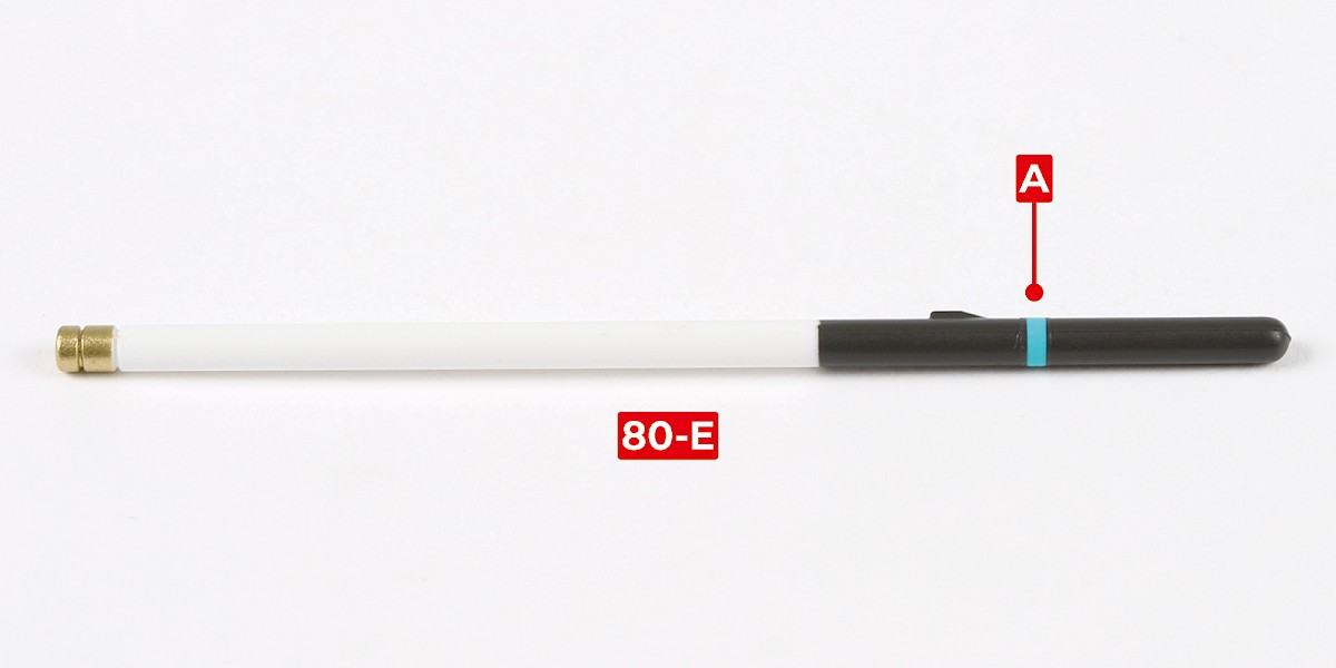
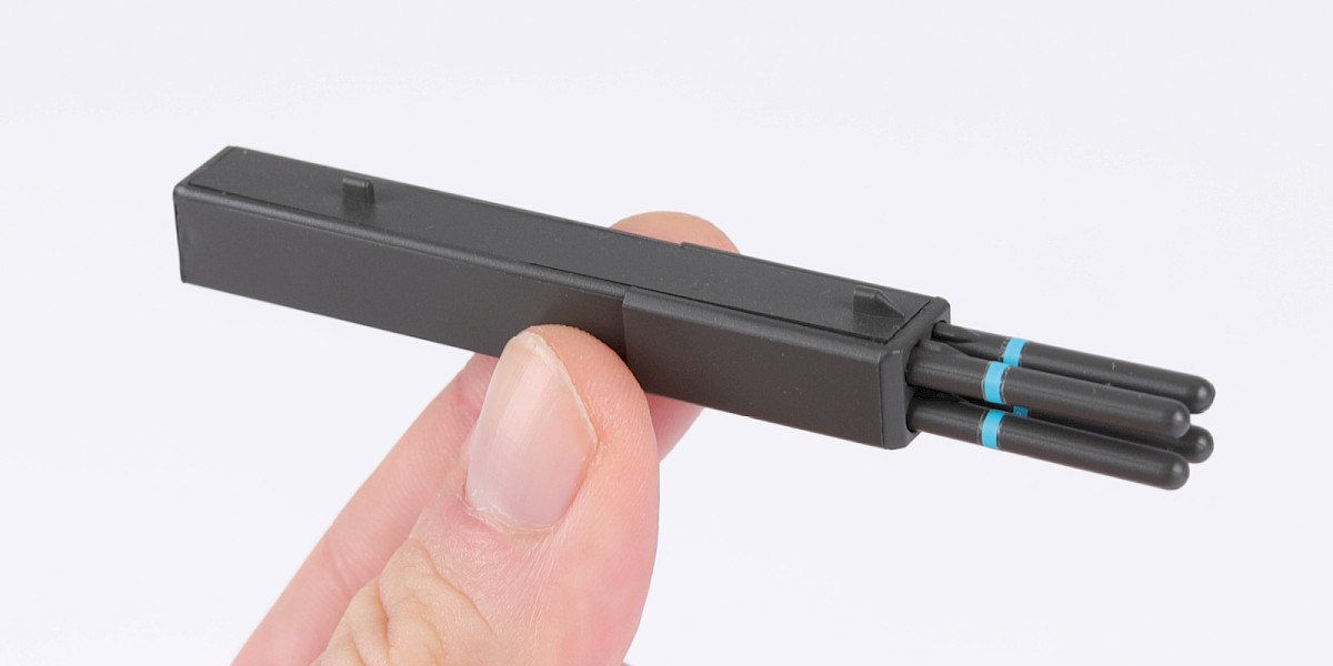
Apply decal A to 80-E.
Repeat to make four missiles ensuring the blue decals are aligned.
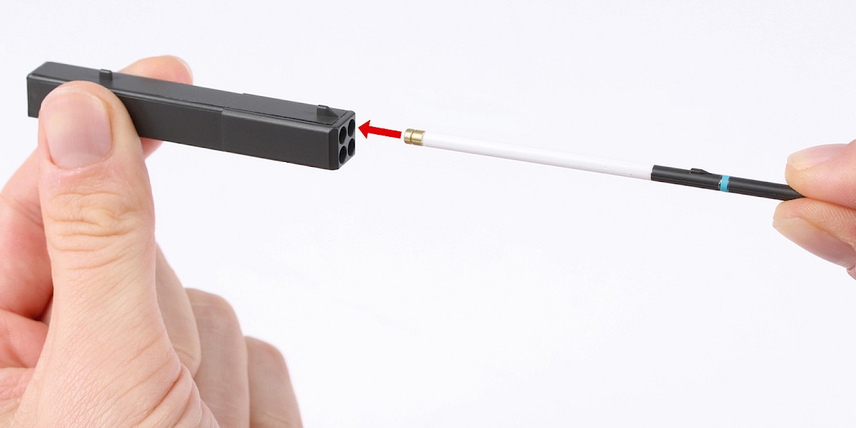
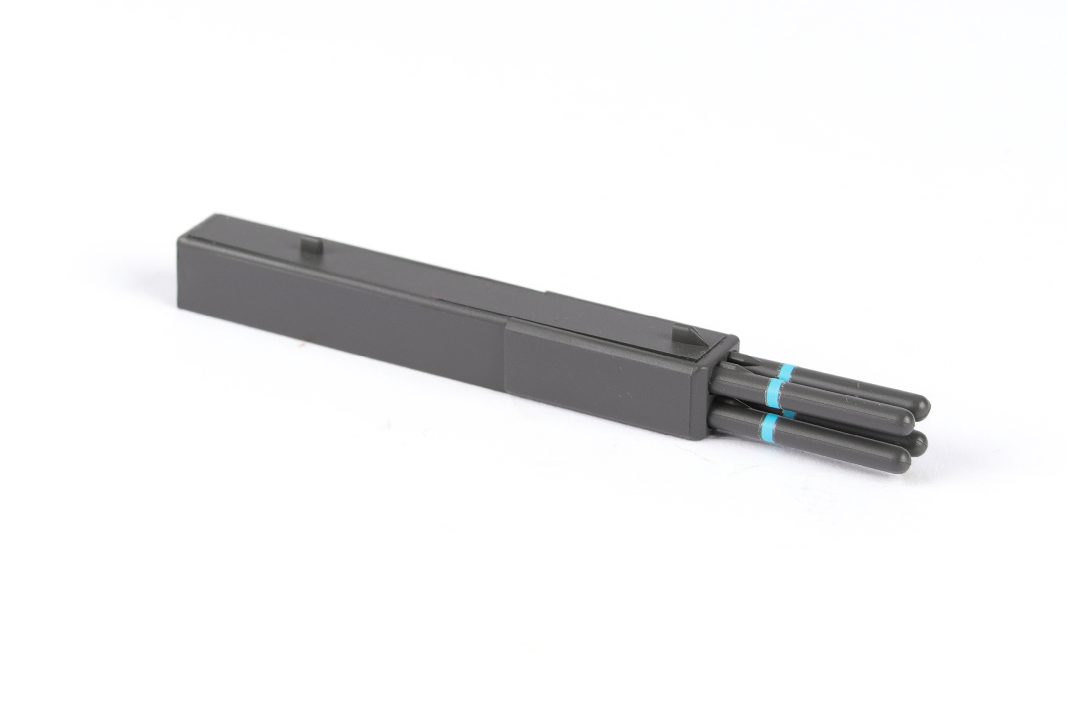
Step 4
Load the missiles into the missile launcher.
STAGE COMPLETE
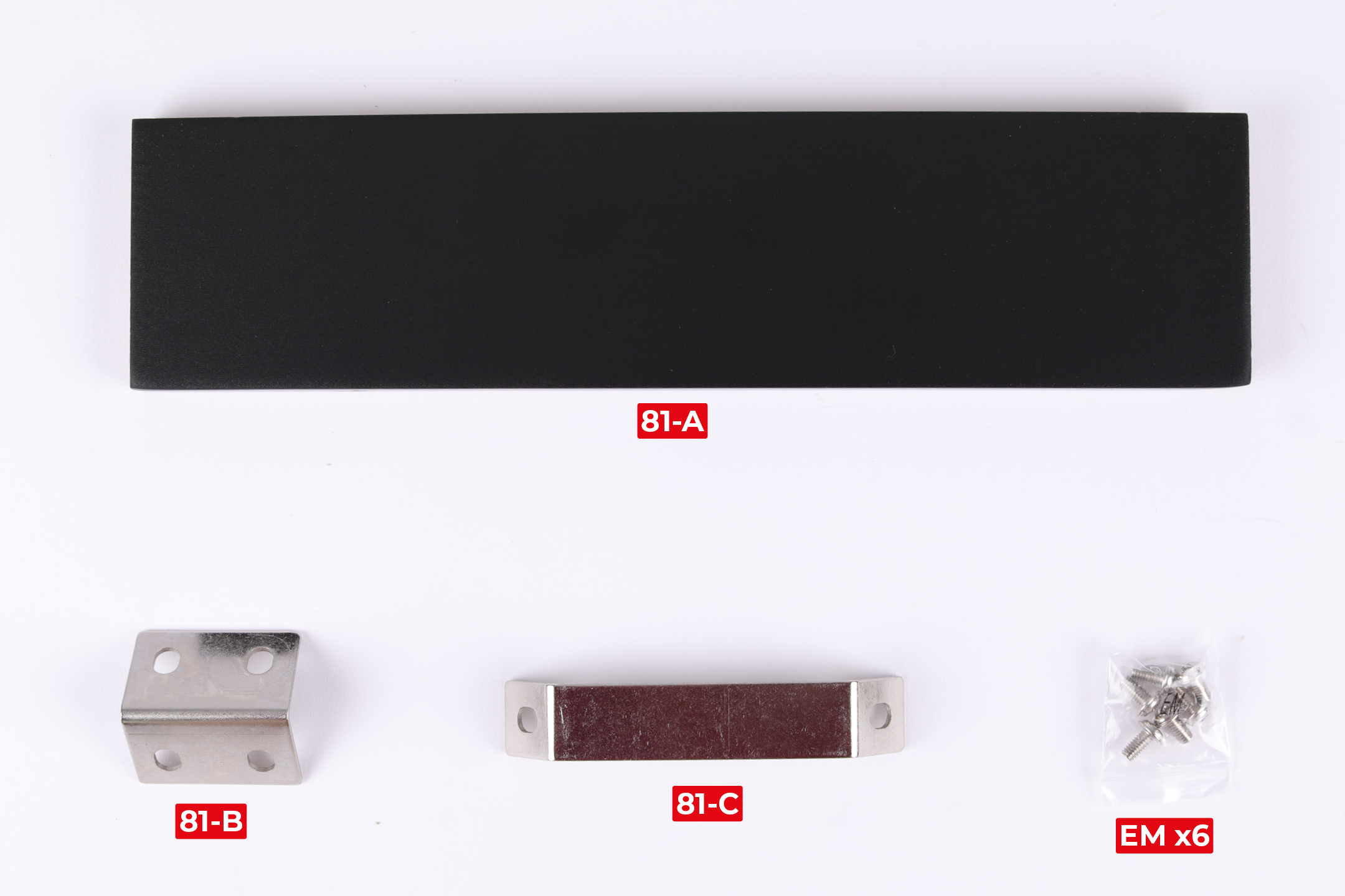
PARTS LIST
| 81-A |
| 81-B |
| 81-C |
| EM x6 |
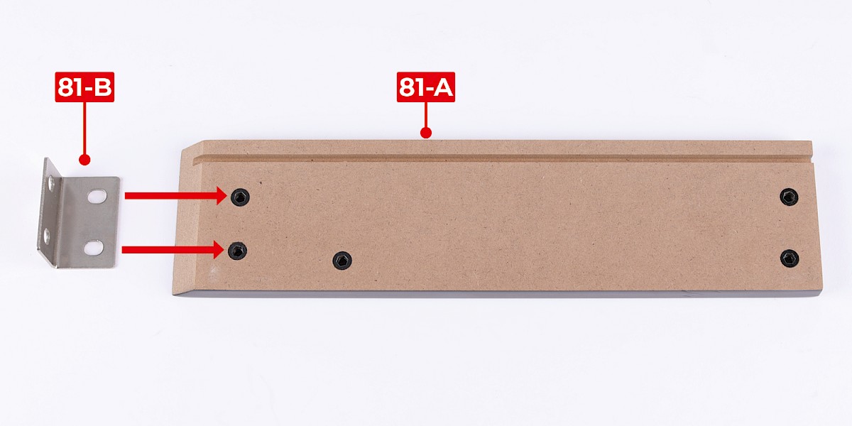
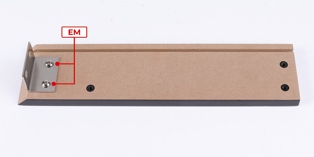
Step 1
Fit 81-B to 81-A.
Secure with 2x EM.
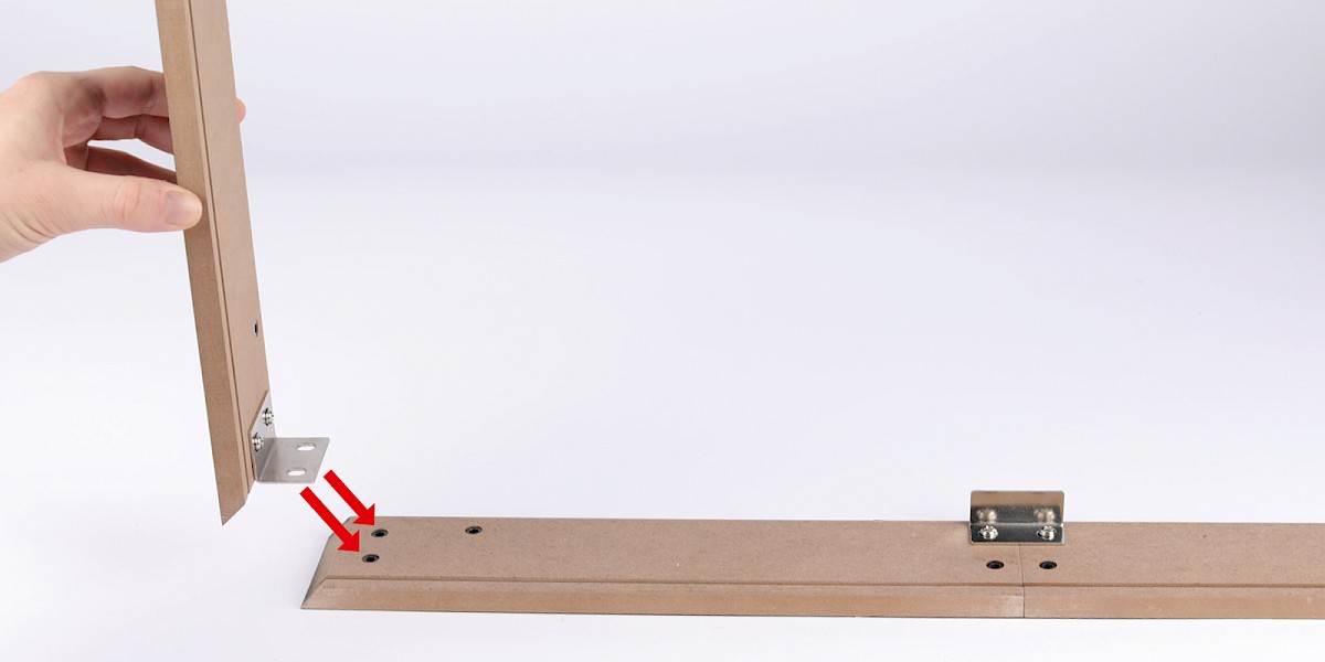
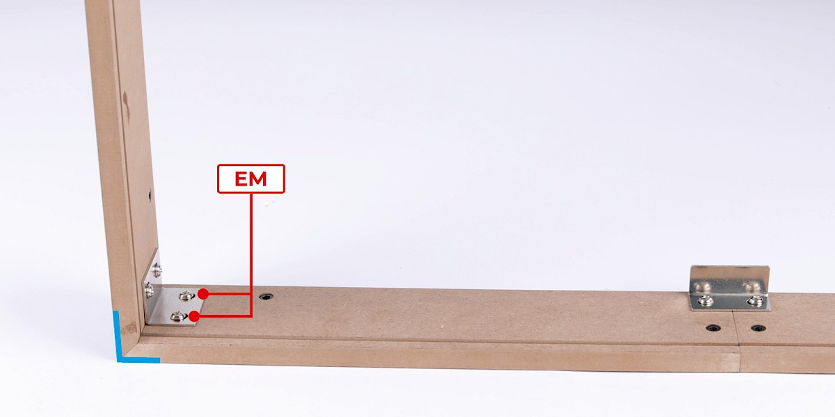
Step 2
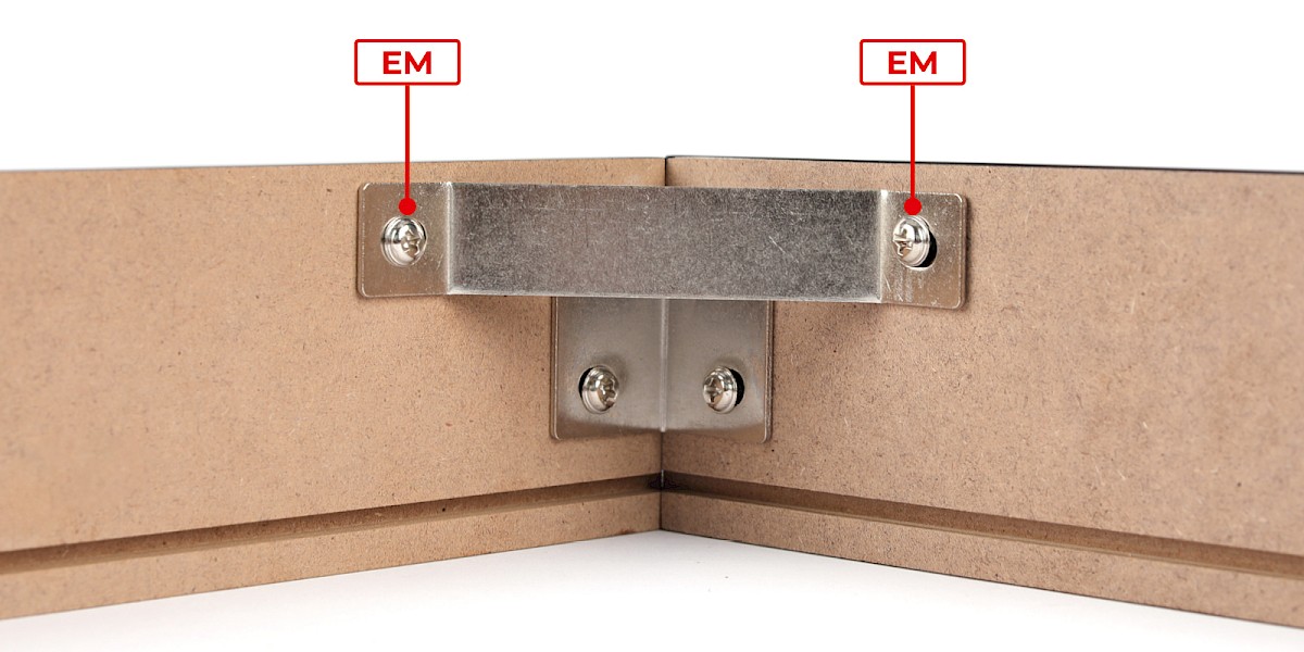
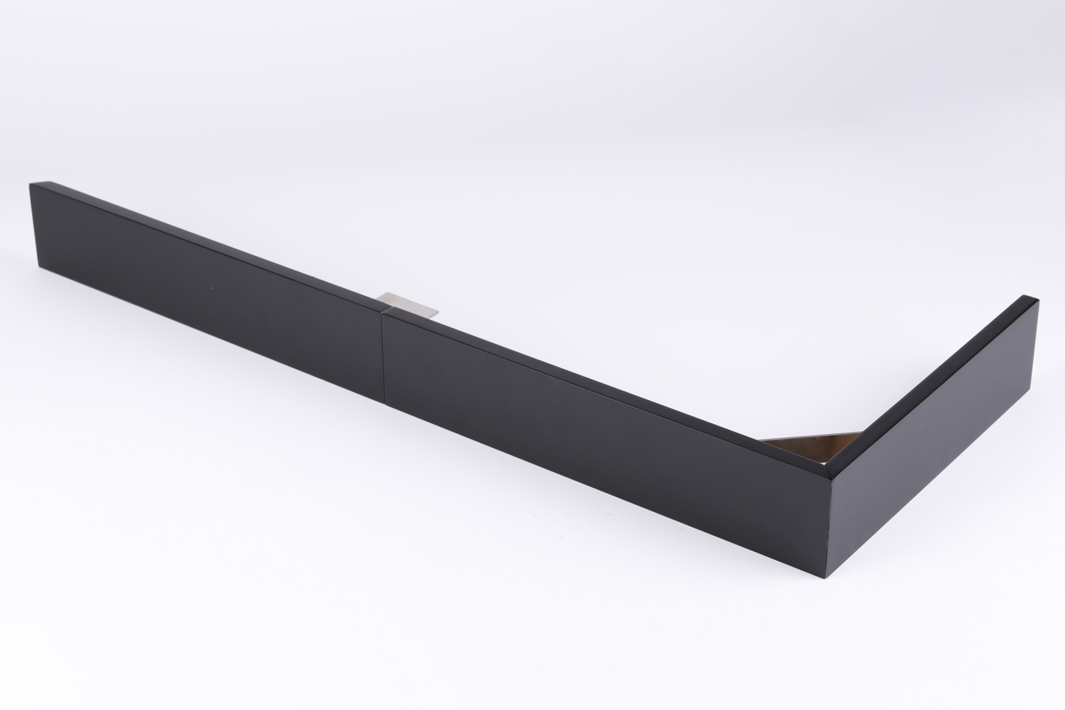
Fit the assembly to the display base panels from stage 55.
Secure with 2x EM. Make sure the panels are aligned at 90 degrees as indicated by the blue line.
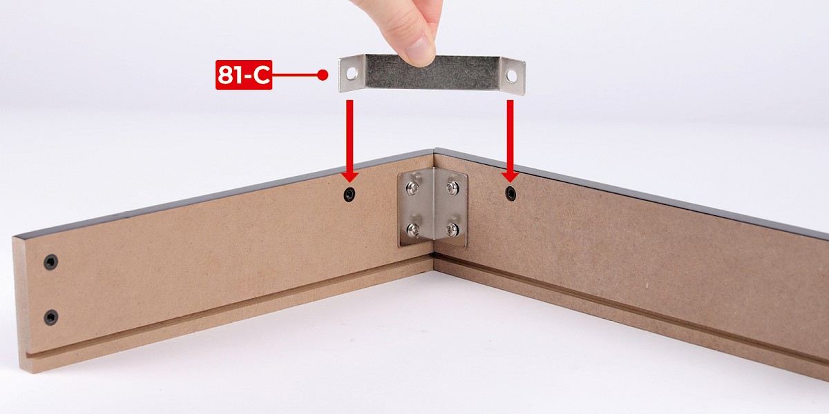
Step 3
Fit 81-C to the assembly.
Secure with 2x EM.
STAGE COMPLETE
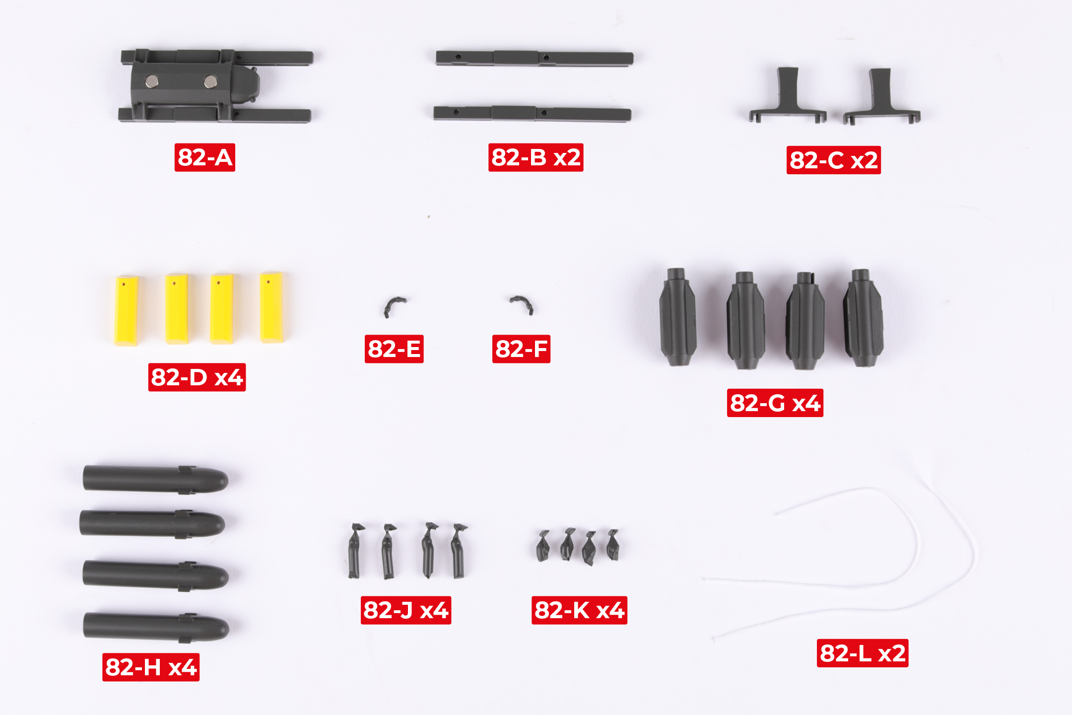
PARTS LIST
| 82-A | 82-G x4 |
| 82-B x2 | 82-H x4 |
| 82-C x2 | 82-J x4 |
| 82-D x4 | 82-K x4 |
| 82-E | 82-L x2 |
| 82-F |
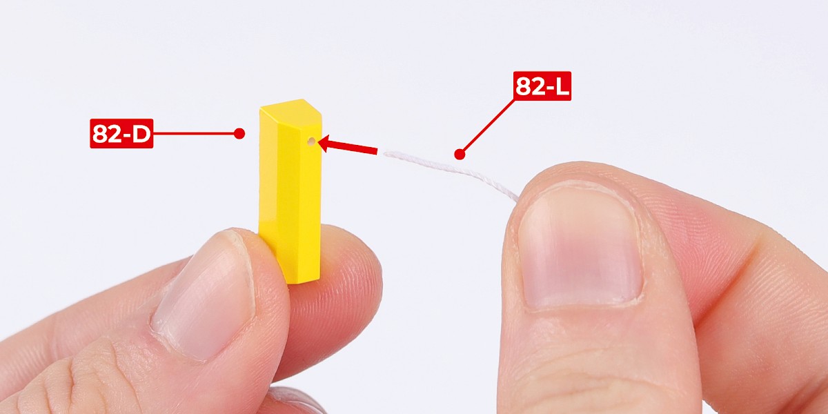
Step 1
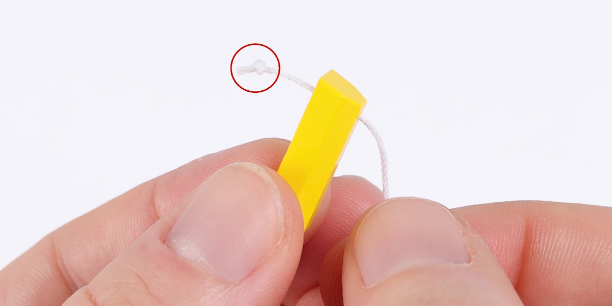
Thread 82-L through 82-D.
Tie a knot in the end as shown.
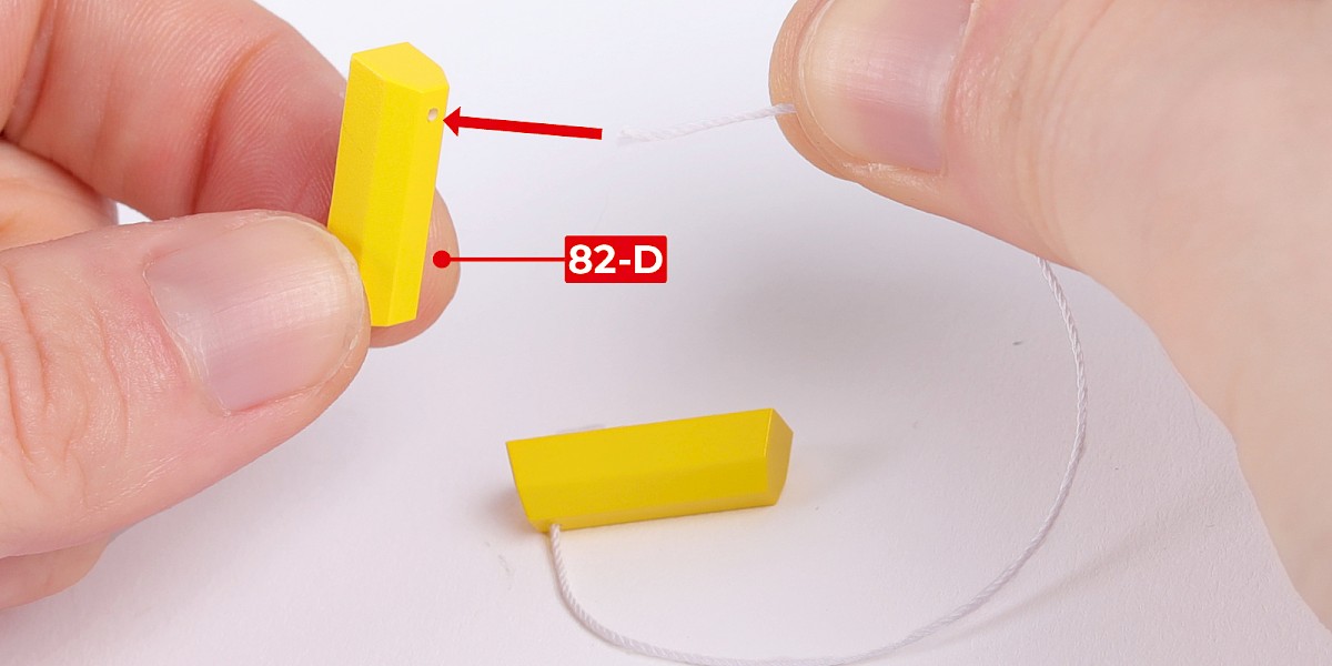
Step 2
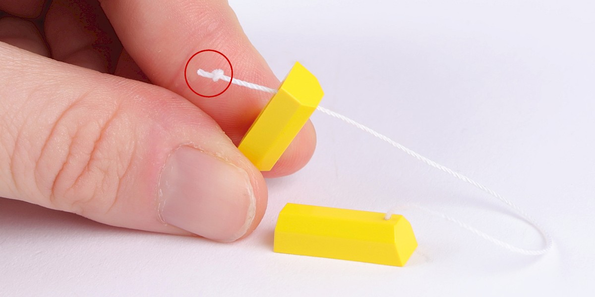
Thread the other end through another 82-D.
Tie a knot in the end as shown.
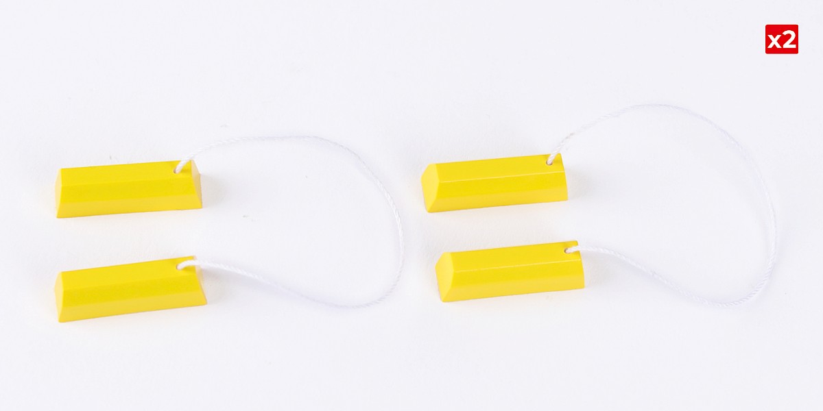
Step 3
Repeat steps 1 and 2 to assemble another wheel chock.
Step 4
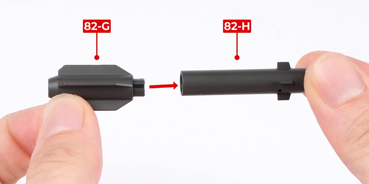
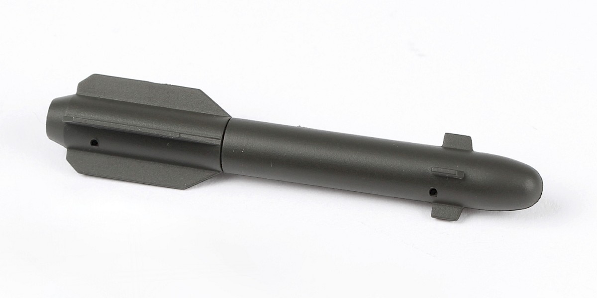
You will now build the Hellfire missiles and an M299 missile launcher.
Fit 82-G to 82-H.
Step 5
Cut parts 82-K and 82-J off the sprues.
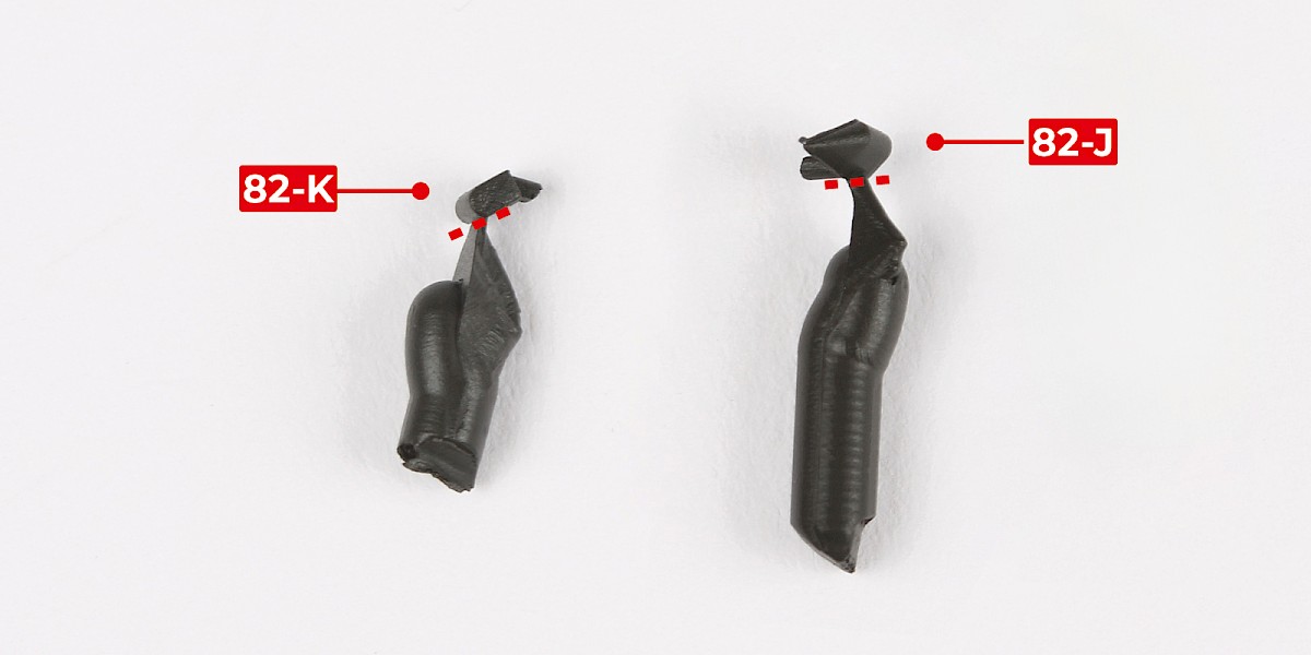
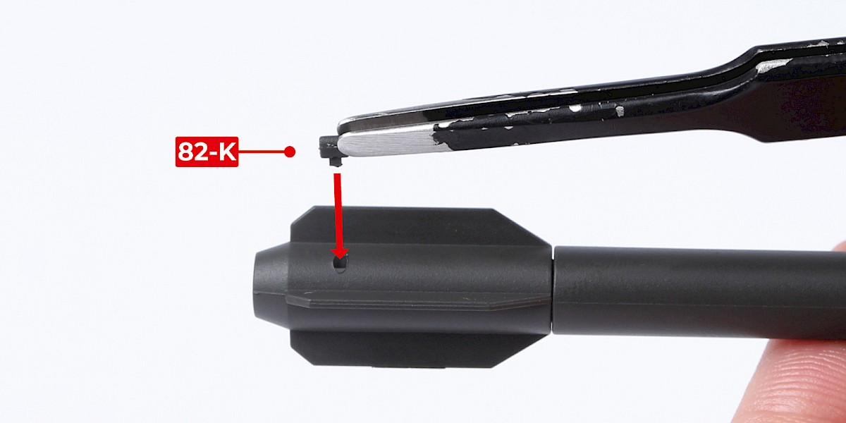
Step 6
Glue 82-K to the assembly.
Step 7
Glue 82-J to the assembly.
Step 8
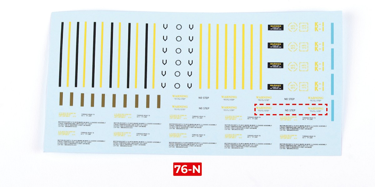
Cut the decals outlined in red from 76-N.
Step 9
Apply decals A, B, C and D to the missile.
Repeat this process to assemble four missiles.
Step 10
Glue one of the missiles to 82-A.
Step 11
Glue a second missile in the same way.
Step 12
Fit 82-C to 82-B. Make sure the parts are in the orientation shown. The recesses on parts 82-B (blue arrows) should face outwards.
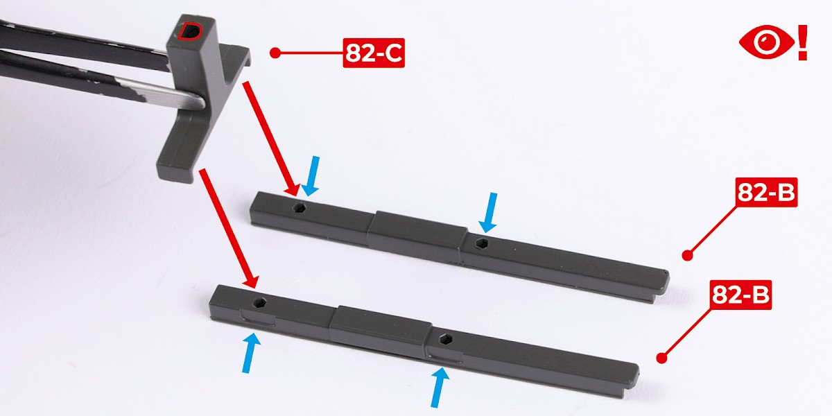
Step 13
Fit another 82-C as shown.

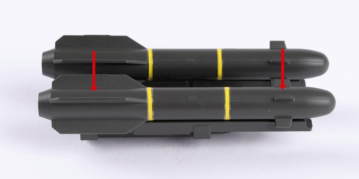
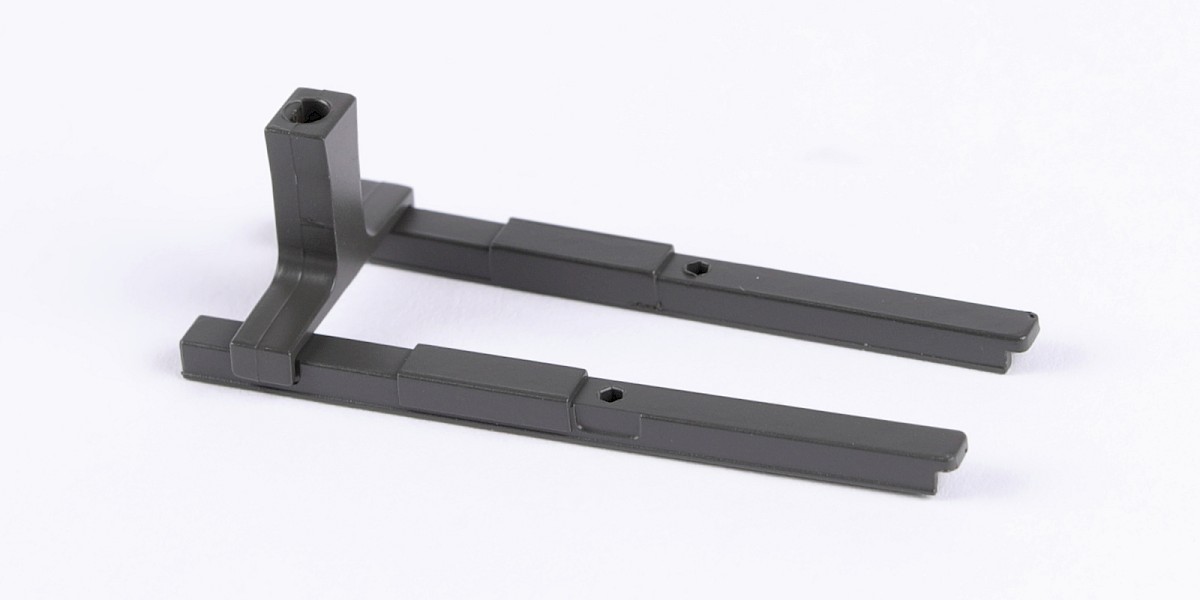
Step 14
Fit the two assemblies together.
Step 15
Glue two missiles to the assembly.
Step 16
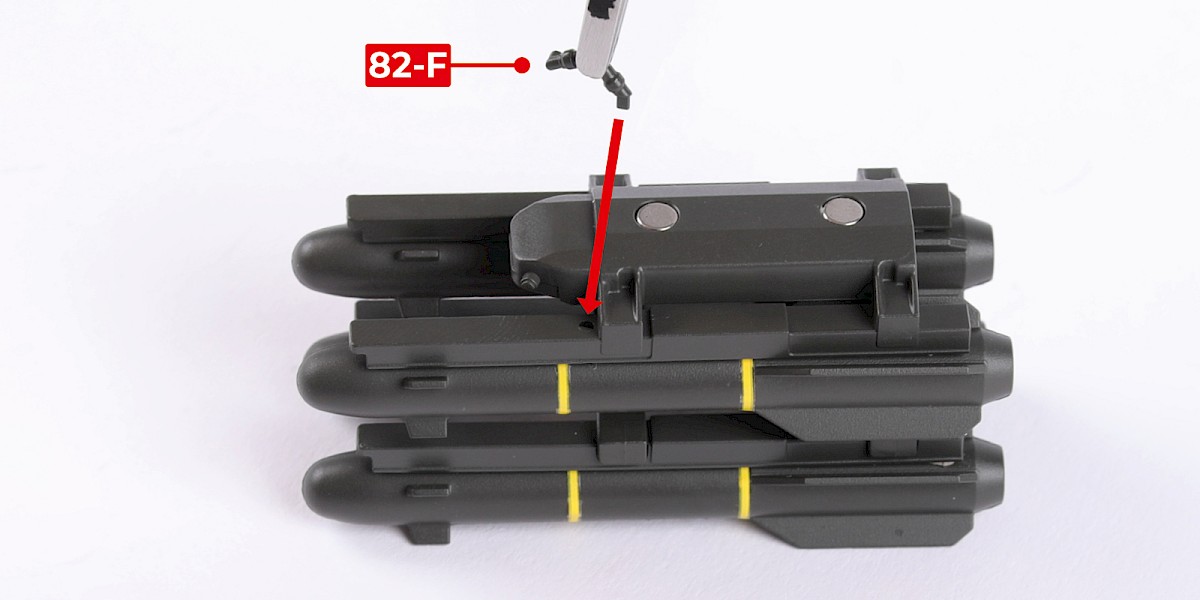
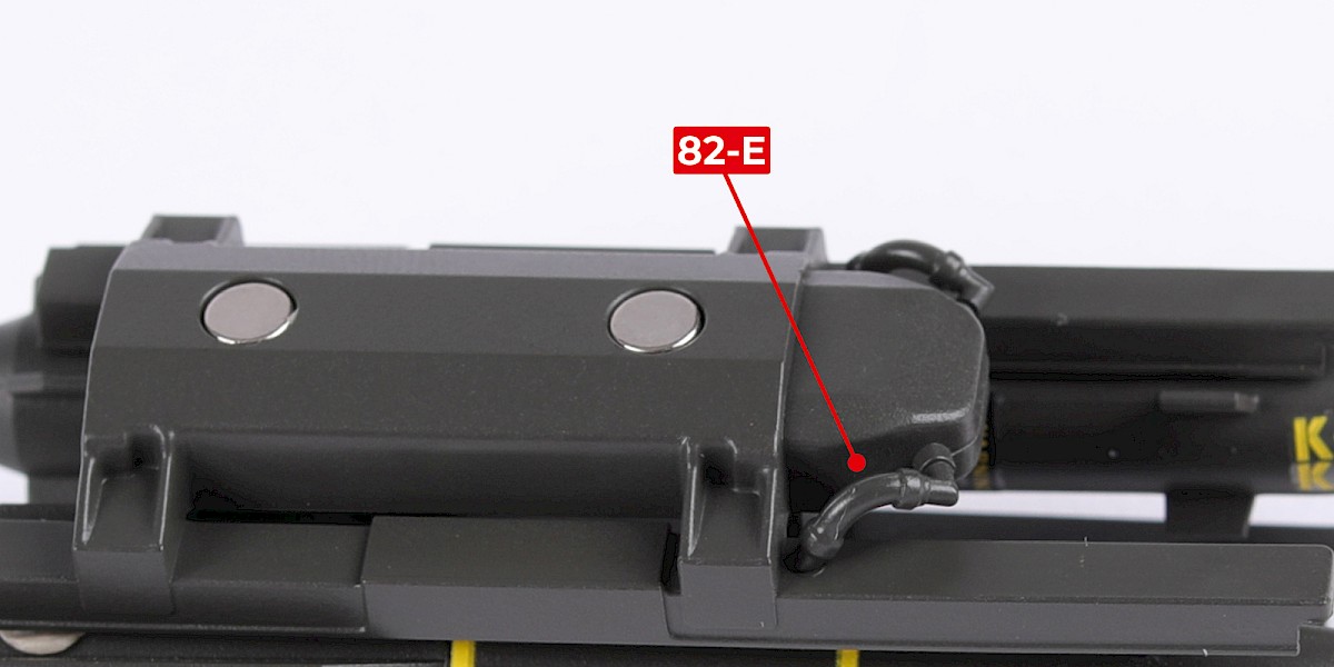
Parts 82-E and 82-F have shaped fittings.
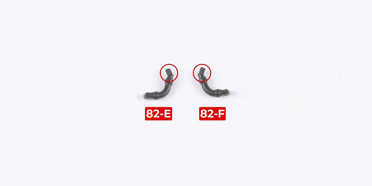
Step 17
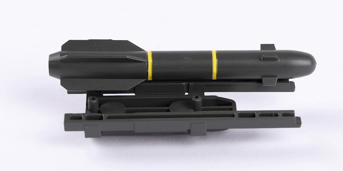
Fit 82-F to the assembly.
Step 18
Fit 82-E to the assembly.
Step 19
Cut the decals outlined in red from 76-N.
Step 20
Apply decals E and F to the assembly.
STAGE COMPLETE
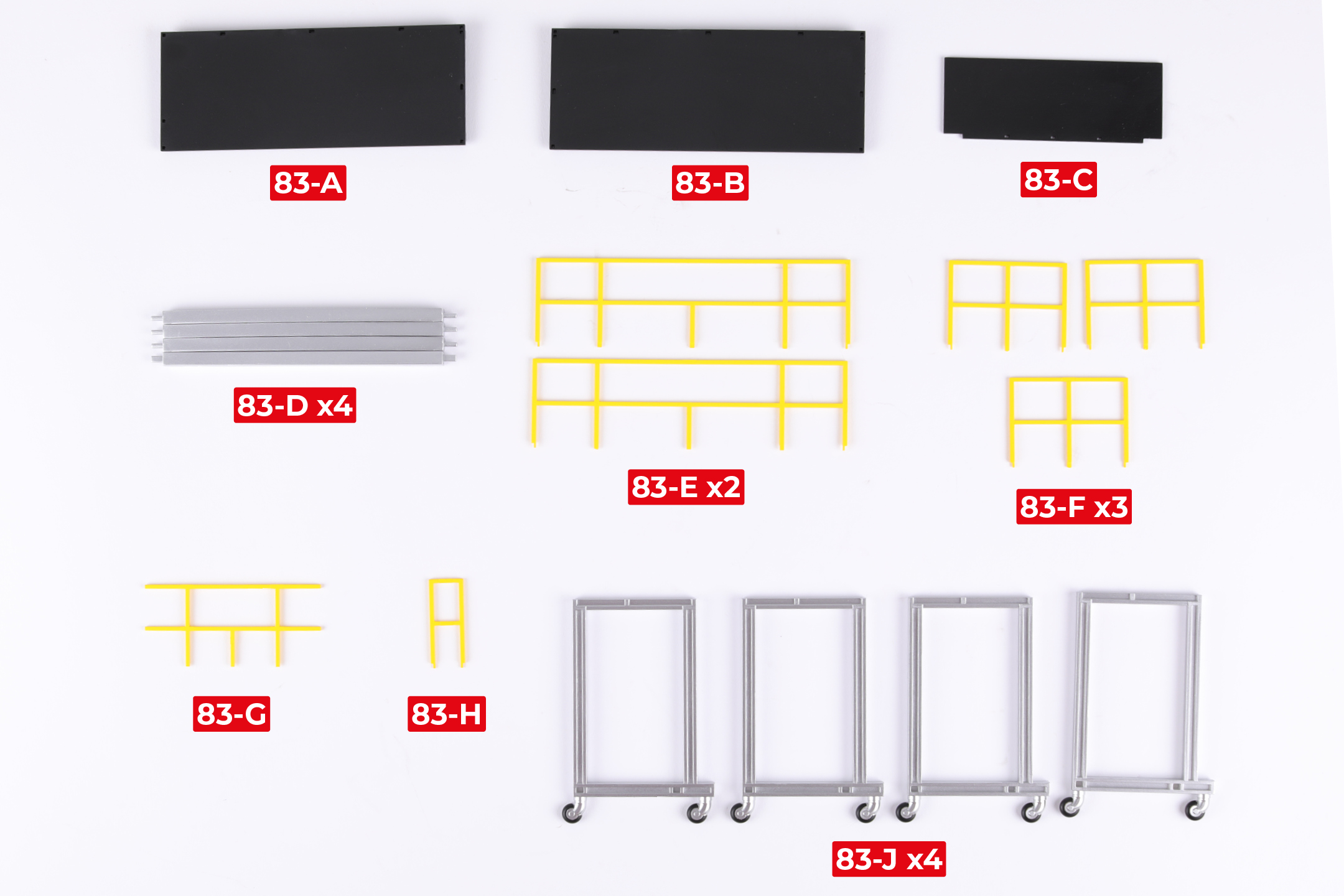
PARTS LIST
| 83-A | 83-F* x3 |
| 83-B | 83-G |
| 83-C | 83-H |
| 83-D x4 | 83-J x4 |
| 83-E x2 |
* An extra part 83-F will be included in Pack 12.
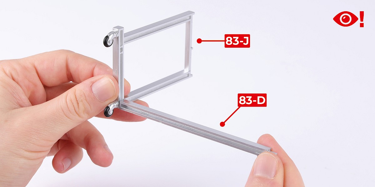
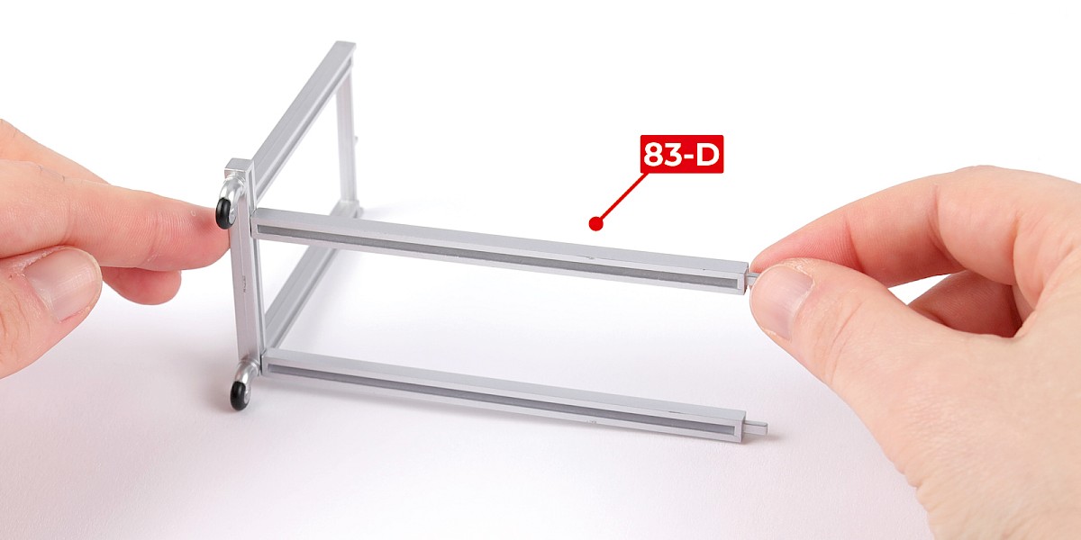
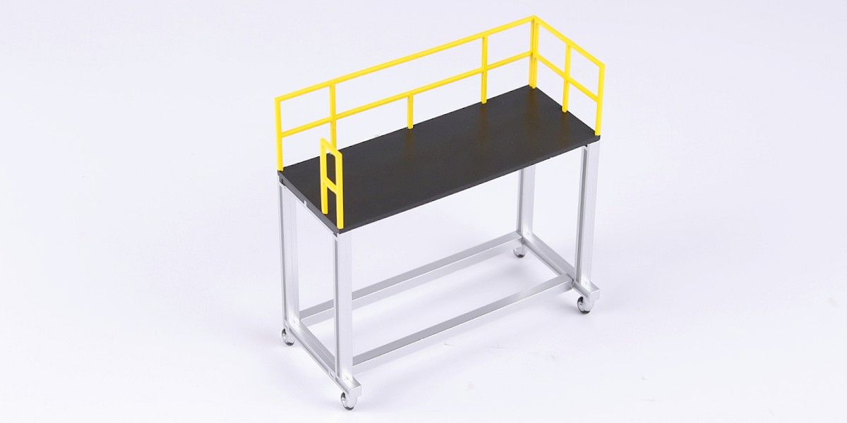
Step 1
Glue 83-D to 83-J. Do not allow the glue to dry, you may need to adjust the parts.
Glue another 83-D to the assembly.
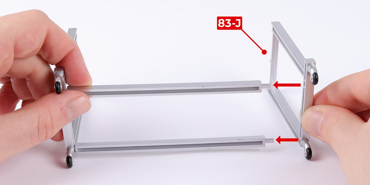
Step 2
Glue 83-J to the assembly.
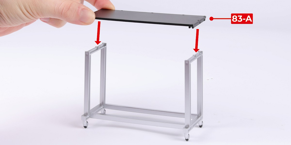
Glue 83-A (marked "1") to the assembly.
Step 3
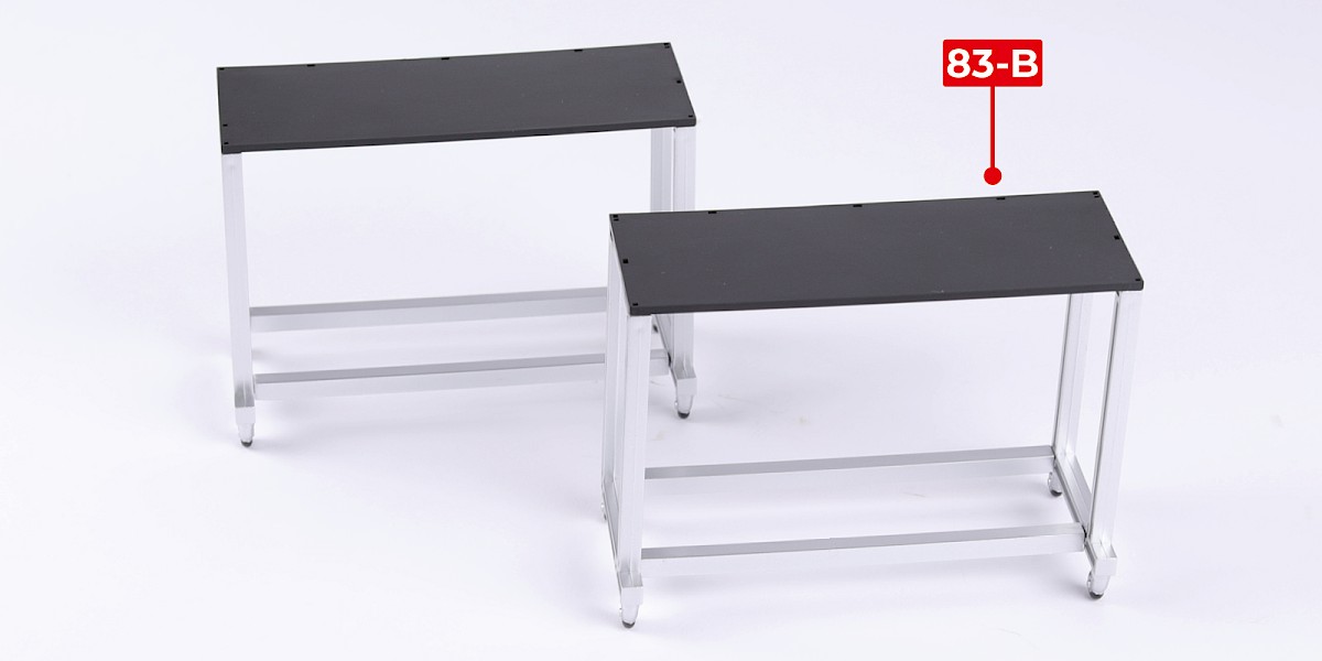
Repeat steps 1 and 2 with 83-B (marked "2").
Step 4
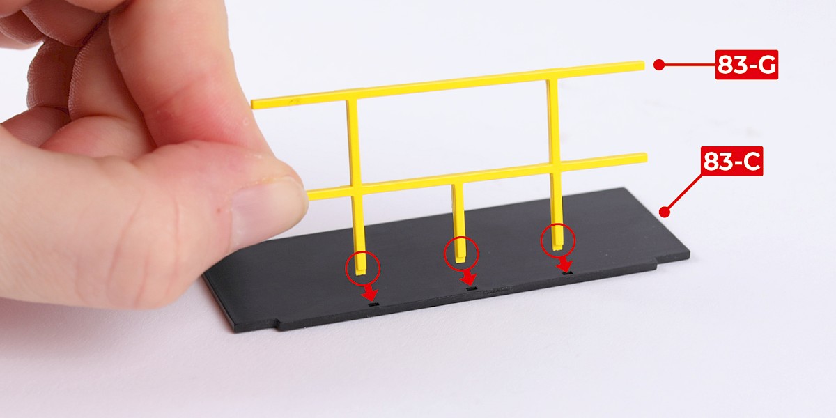
Glue 83-G to 83-C.
The rails should always be glued with the recesses (circled) facing outwards.
Step 5
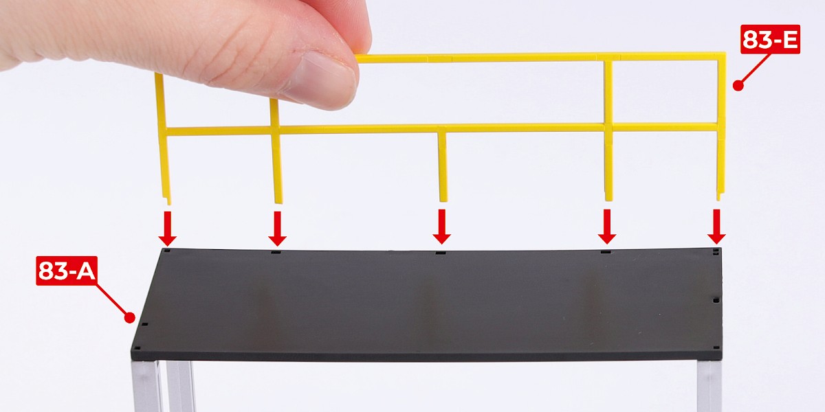
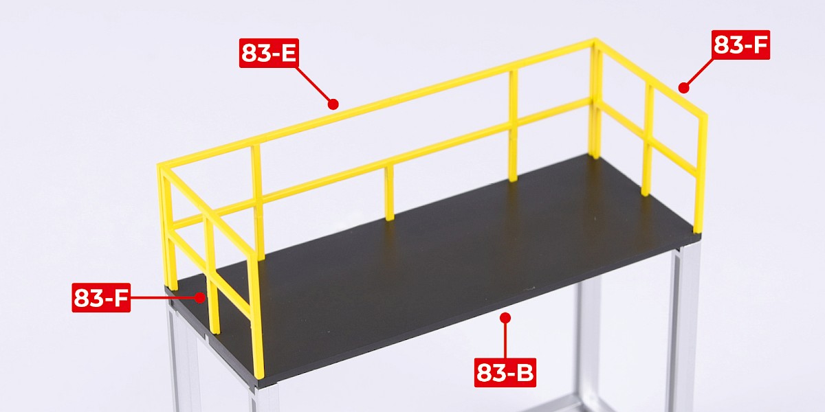
Glue 83-E to 83-A.
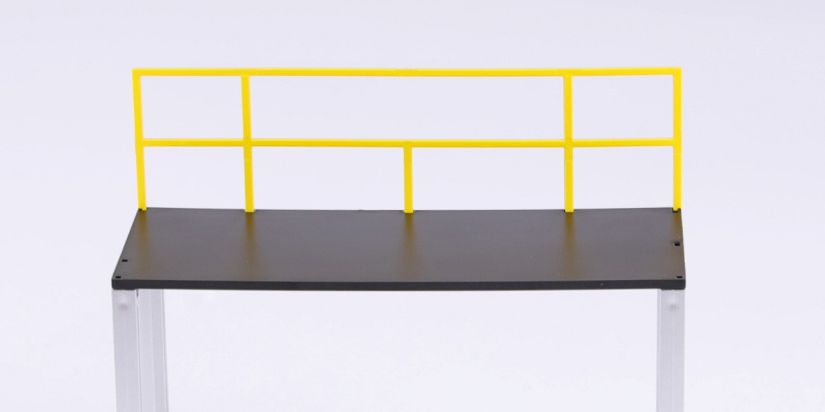
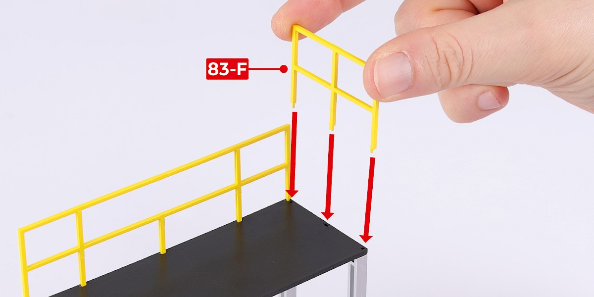
Step 6
Glue 83-F to the assembly.
An extra part 83-F will be included in Pack 12.
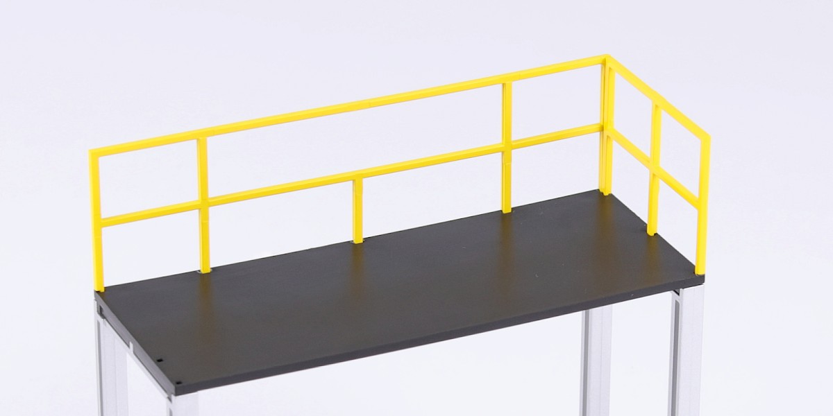
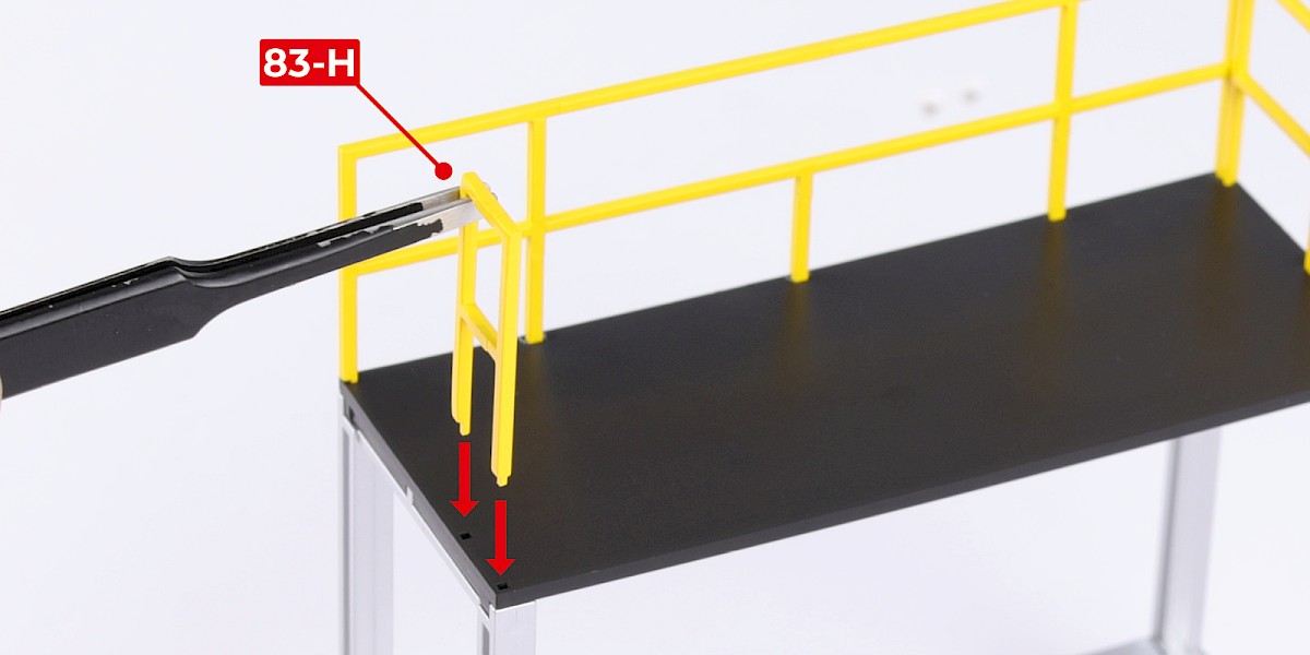
Step 7
Glue 83-H to the assembly.
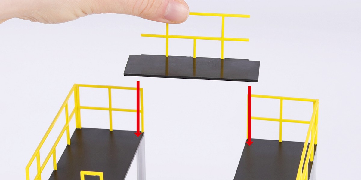
Step 8
Glue the rails to the second platform in the same way.
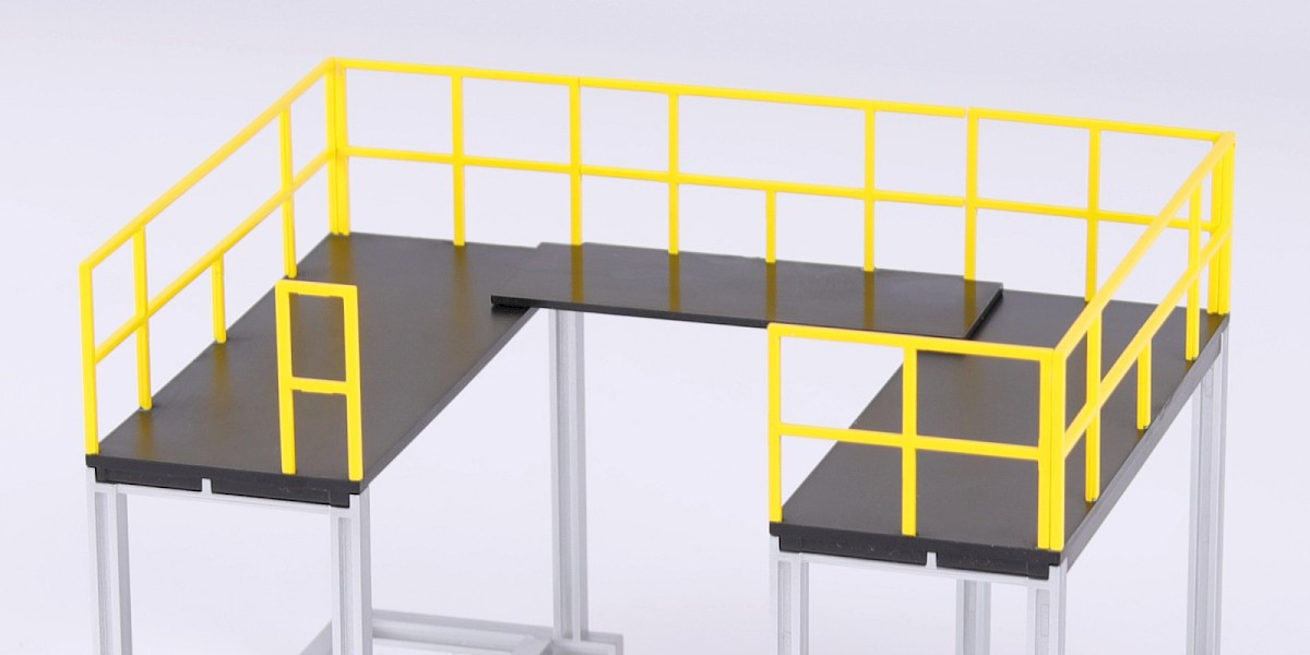
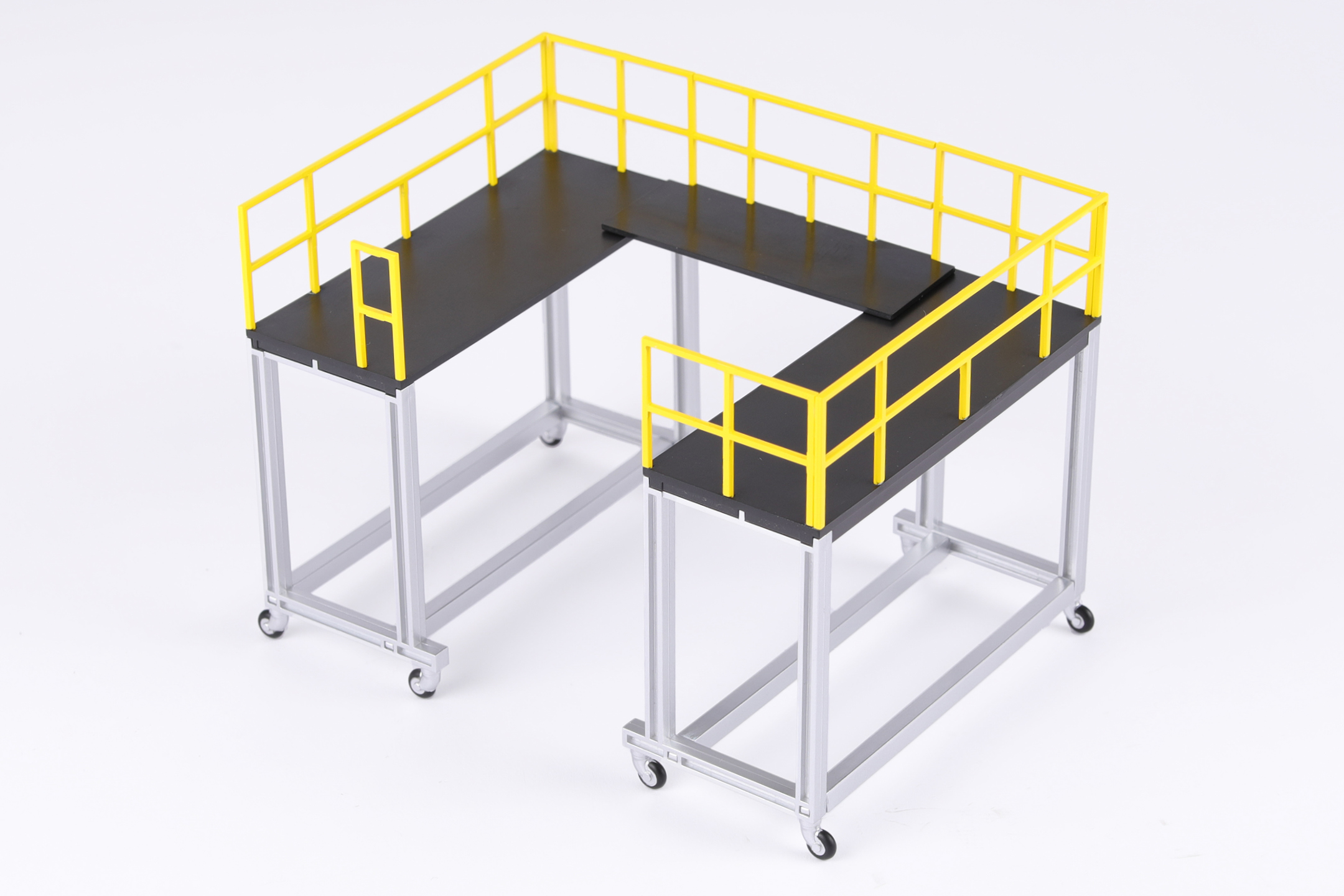
Step 9
The small platform can be used to link the two mobile platforms.
STAGE COMPLETE
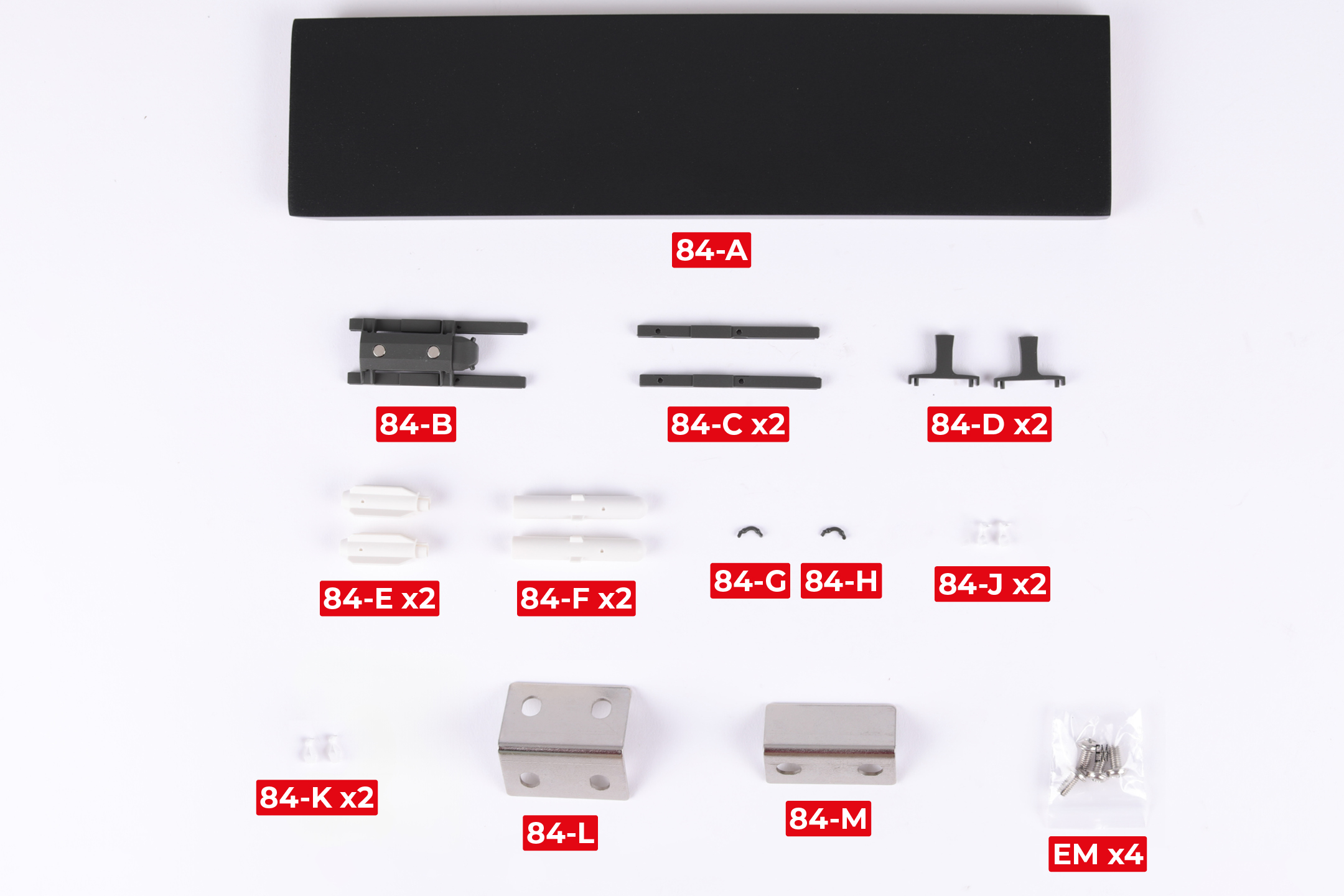
PARTS LIST
| 84-A | 84-H |
| 84-B | 84-J x2 |
| 84-C x2 | 84-K x2 |
| 84-D x2 | 84-L |
| 84-E x2 | 84-M |
| 84-F x2 | EM x4 |
| 84-G |
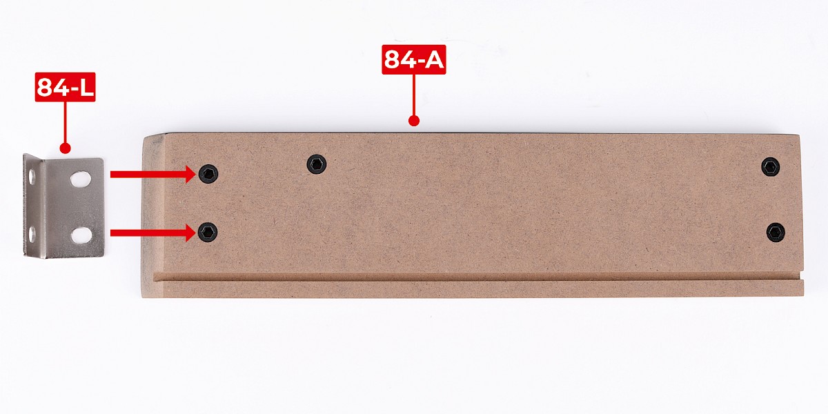
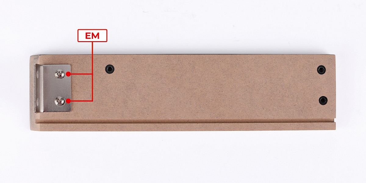
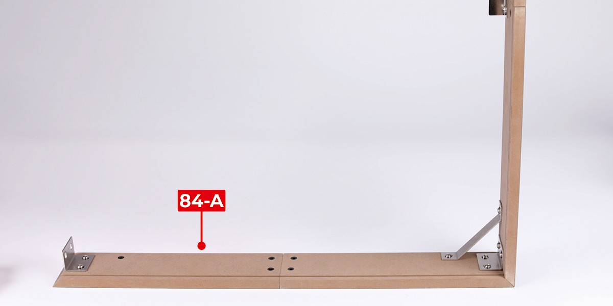
Step 1
Fit 84-L to 84-A.
Secure with 2x EM.
Step 2
Fit the assembly to the display base panels from stage 81.
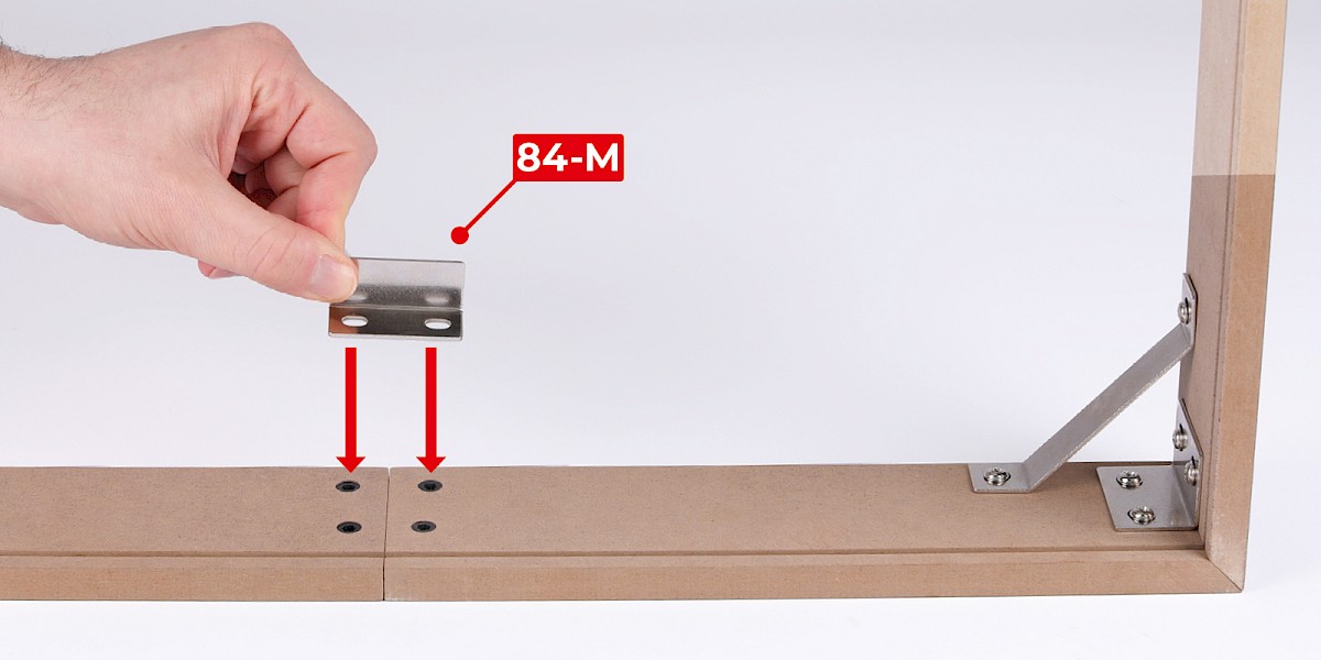
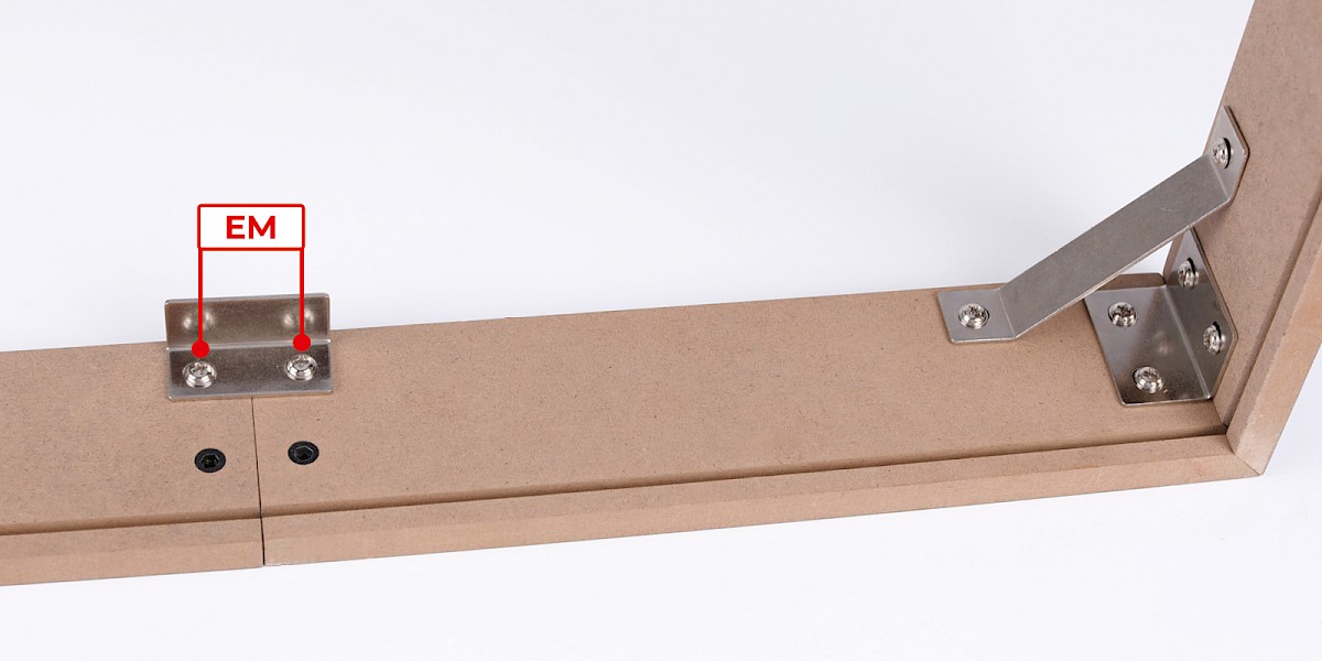
Step 3
Fit 84-M to the assembly.
Secure with 2x EM.
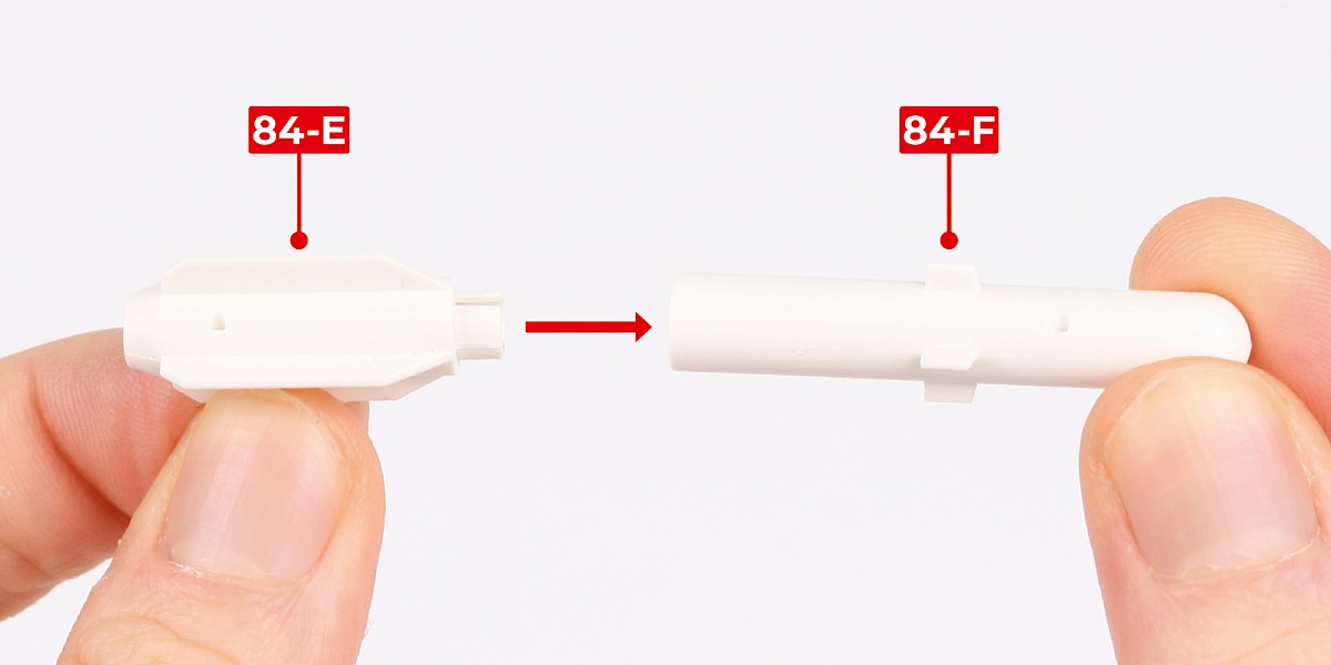
Step 4
Fit 84-E to 84-F.

Step 5
Cut parts 84-K and 84-J off the sprues.

Step 6
Glue 84-J to the assembly.


Step 7
Glue 84-K to the assembly.

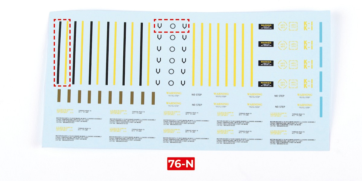
Step 8
Cut the decals outlined in red from 76-N.

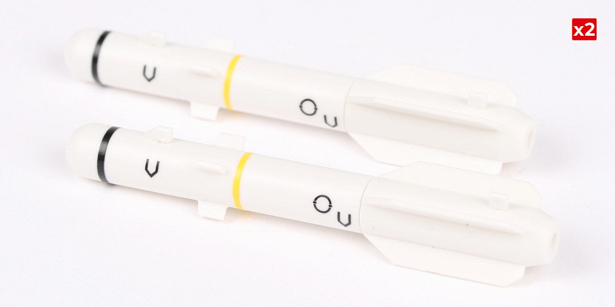
Step 9
Apply decals A, B, C and D to the missile.
Repeat this process to assemble two missiles.

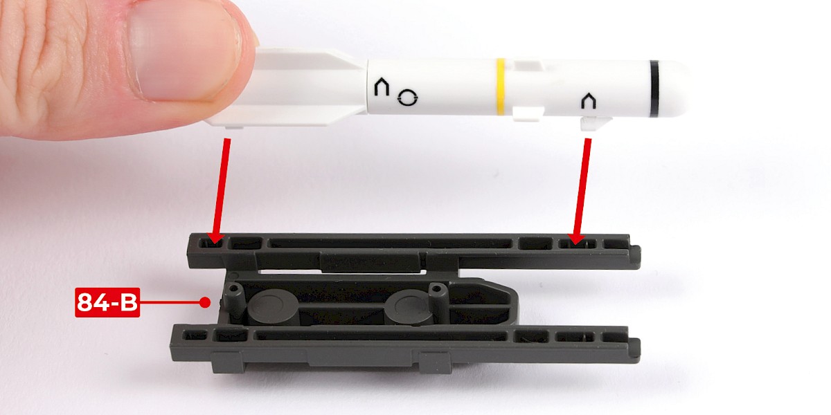
Step 10
Glue one of the missiles to 84-B.
Step 11
Glue a second missile in the same way.

Step 12
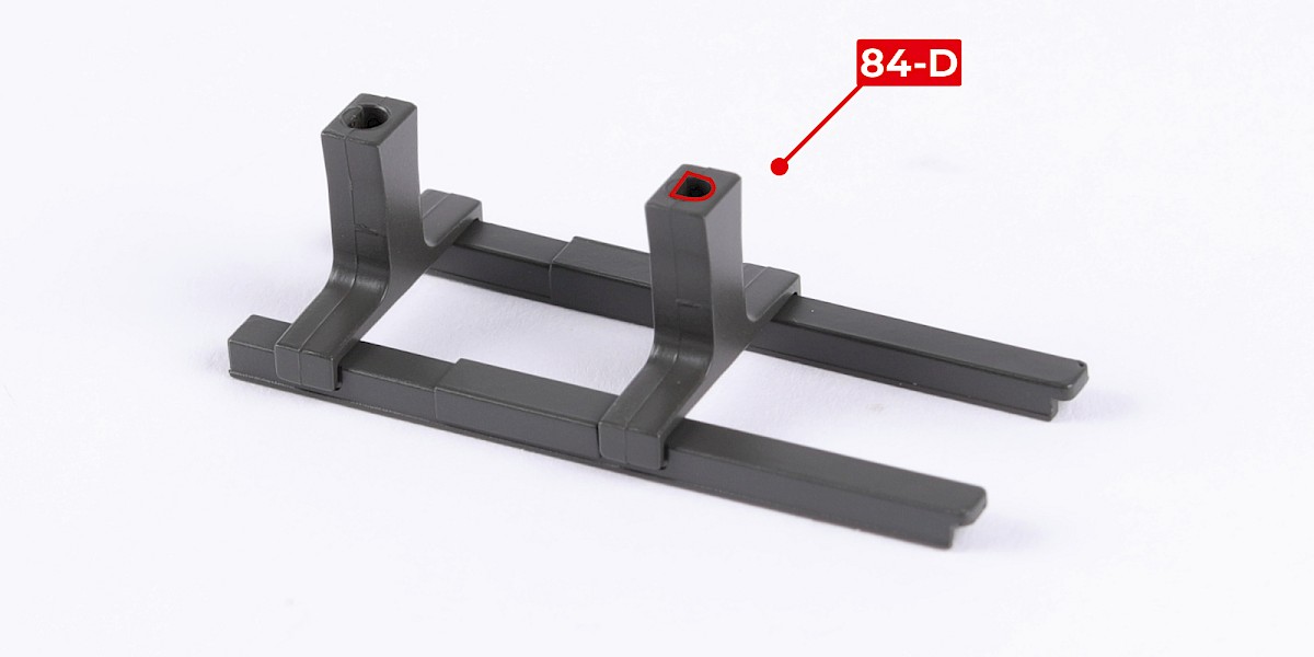
Fit 84-D to 84-C. Make sure the parts are in the orientation shown.


Step 13
Fit another 84-D as shown.
Step 14
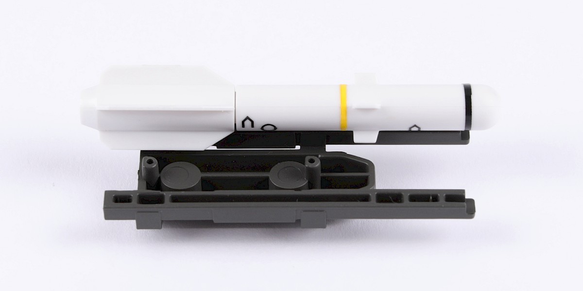
Fit the two assemblies together.
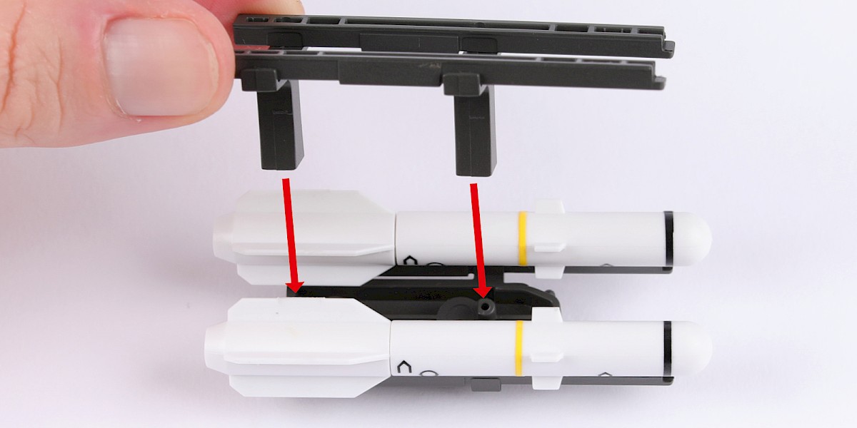

Step 15
Glue two missiles (stage 79) to the assembly.

Step 16
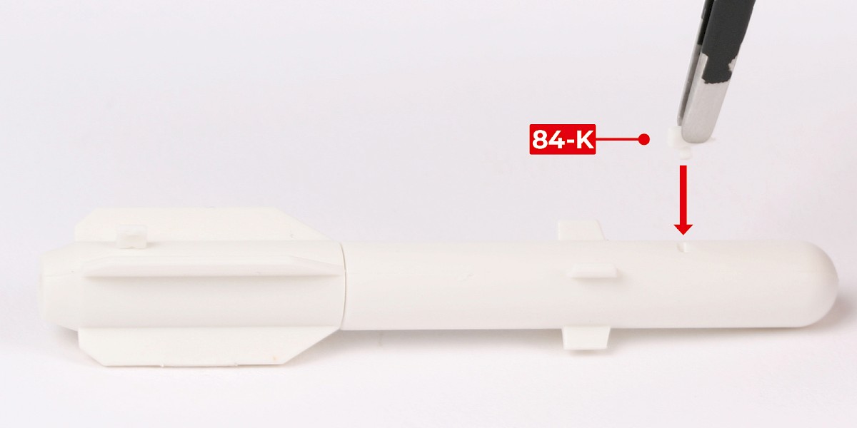
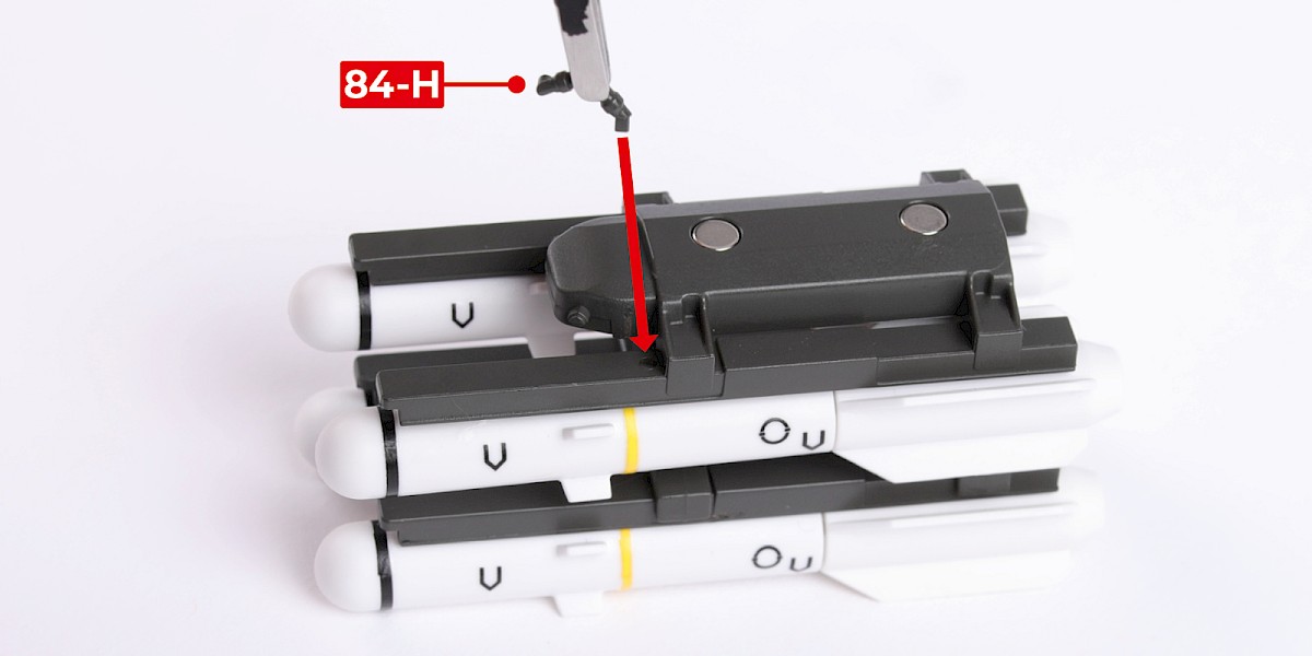
Parts 84-H and 84-G have shaped fittings.
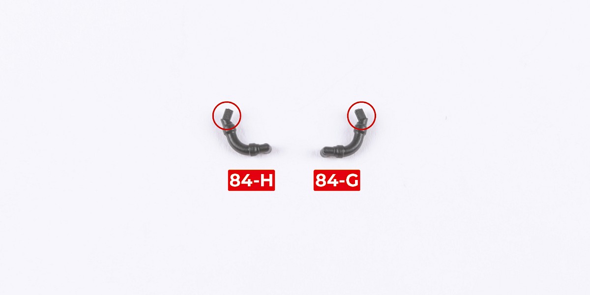
Step 17
Fit 84-H to the assembly.
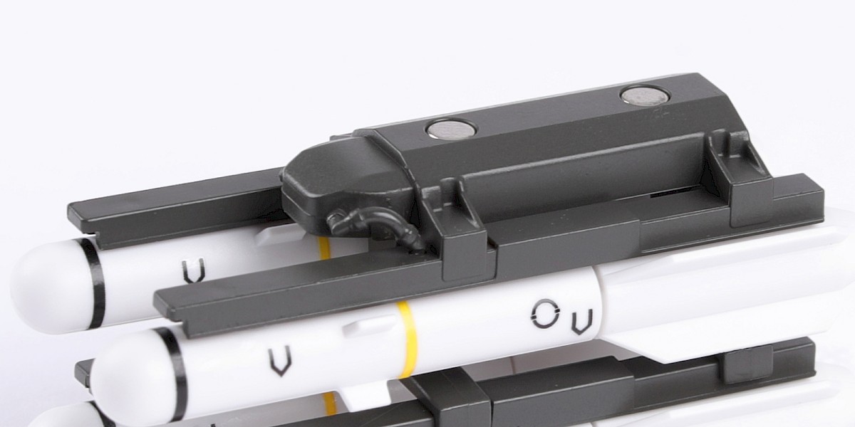
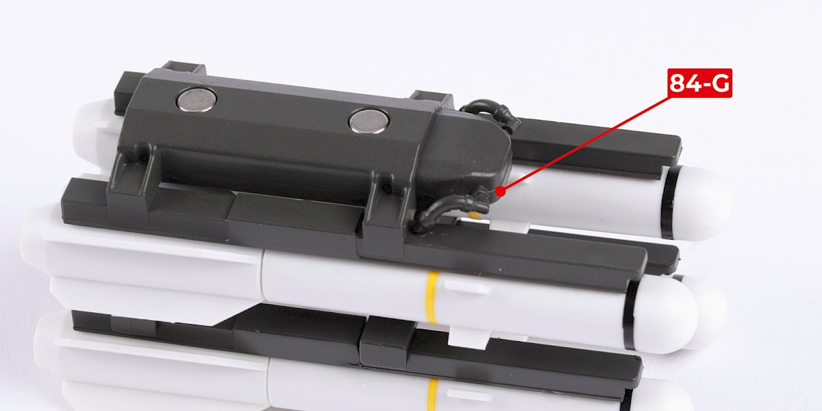
Step 18
Fit 84-G to the assembly.
Step 19
Cut the decals outlined in red from 76-N.

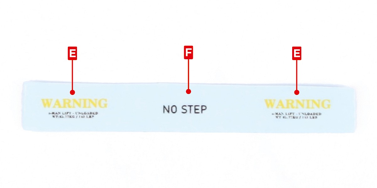
Step 20
Apply decals E and F to the assembly.


STAGE COMPLETE