Pack 11
BUILD INSTRUCTIONS
Advice from the experts
Spare screws are included with each part. Occasionally, you may be instructed to keep spare or unused screws for a later stage. Keep these spares in a safe place and label them correctly.
Please make sure you don’t mix up the screws. They look quite similar, but the threads do vary slightly. Using the wrong screws may damage the parts. Only use the correct size screwdriver that fits the screw head firmly.
When securing parts together using multiple screws, fit each screw loosely to ensure all the parts are correctly aligned before gently tightening them firmly, but not overtight, in the order in which you placed them.
The screwdriver can be magnetized by stroking it with a magnet (fridge magnet, etc.) enabling it to hold the screws and make assembly easier.
If a screw is tight going into a metal part, do not force it as you may shear the head off. Remove it and put a tiny smear of Vaseline, soap or light oil on the thread. That will lubricate it and make it easier to tighten.
Some parts will require a little glue for assembly. Please apply glue sparingly and use a cocktail stick so that you don’t use too much nor apply the glue too heavily. We recommend superglue gel or Extra Thin Liquid modeling glue. Where possible, parts should be test-fitted in place before gluing.
Make sure you have good ventilation when using adhesives and to replace caps firmly.
Use a magnet to help find screws that have fallen on the floor.
Use masking tape to hold parts temporarily in place.
Cut parts from a sprue (framework) with side cutters or a craft knife. Side cutters tend to be easiest.
During the course of this build, you will receive many pieces that you will assemble immediately – following the instructions in the corresponding stage – and other pieces that you should store safely to one side, for use in future assembly stages.
Always protect the paint finish on components by placing a cutting mat, sheet of white paper or soft cloth on your work surface.
When plugging cables in, ensure the power is switched off. Tweezers can be used to fit the PVC cables by gripping carefully around 5mm from the end of the cable. If a cable needs to be removed from a socket, do not pull on the cable as this could damage the connection. Grip the plug with tweezers to remove it.
Left and Right! When building your AH-64 Apache, the left- or right-hand side refers to that side as if you are sitting in the cockpit.
![]() When you see this symbol, pay attention to the instruction text in bold and check the orientation of the parts in the image as this will be particularly important for assembly in later stages.
When you see this symbol, pay attention to the instruction text in bold and check the orientation of the parts in the image as this will be particularly important for assembly in later stages.
WARNING: Some parts are assembled using magnets. These magnets can cause serious injury if they are swallowed. Keep away from children. If you suspect a magnet has been swallowed, seek medical help straight away.
This is not a toy. Not suitable for children under 14 years old due to small parts. Adult supervision required.
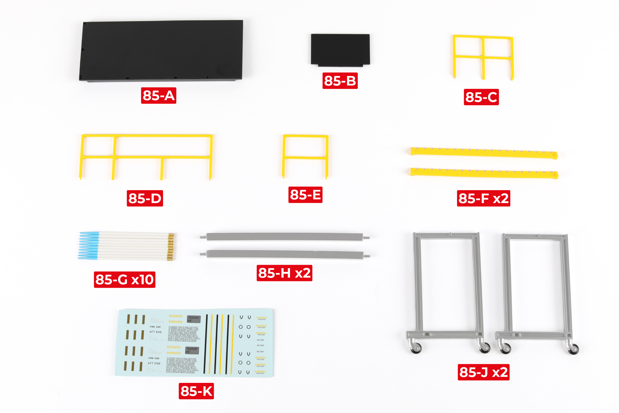
PARTS LIST
| 85-A | 85-F x2 |
| 85-B | 85-G x10 |
| 85-C | 85-H x2 |
| 85-D | 85-J x2 |
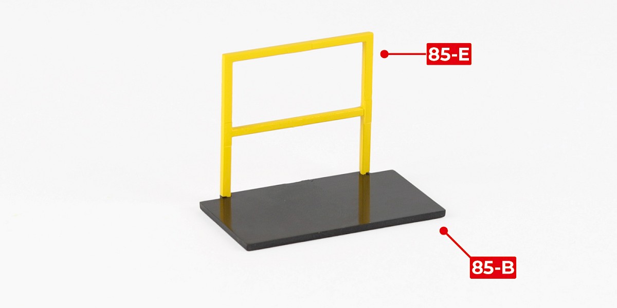
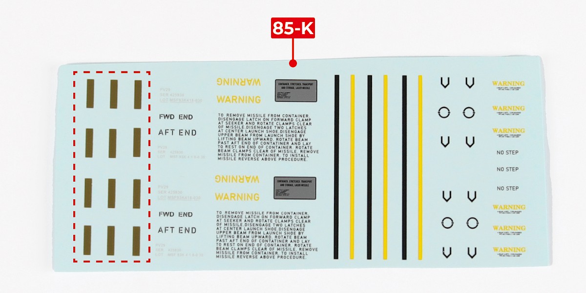
| 85-E | 85-K |
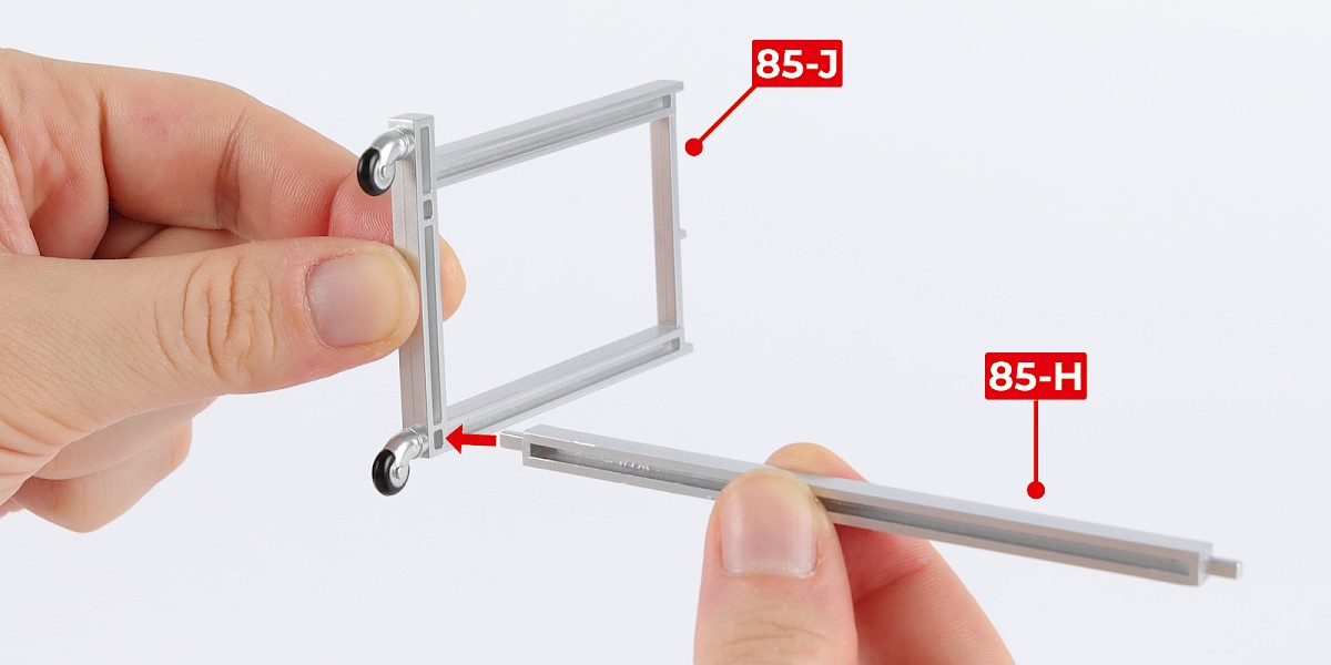
Step 1
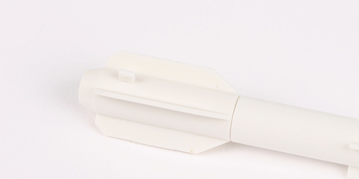
Glue 85-H to 85-J. Do not allow the glue to dry, you may need to adjust the parts.
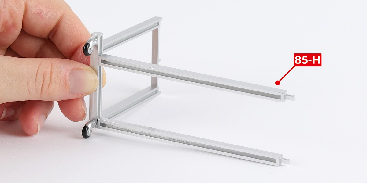
Glue another 85-H to the assembly.
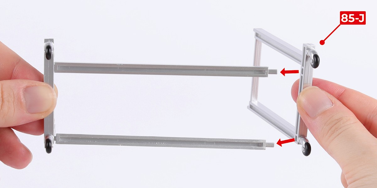
Step 2
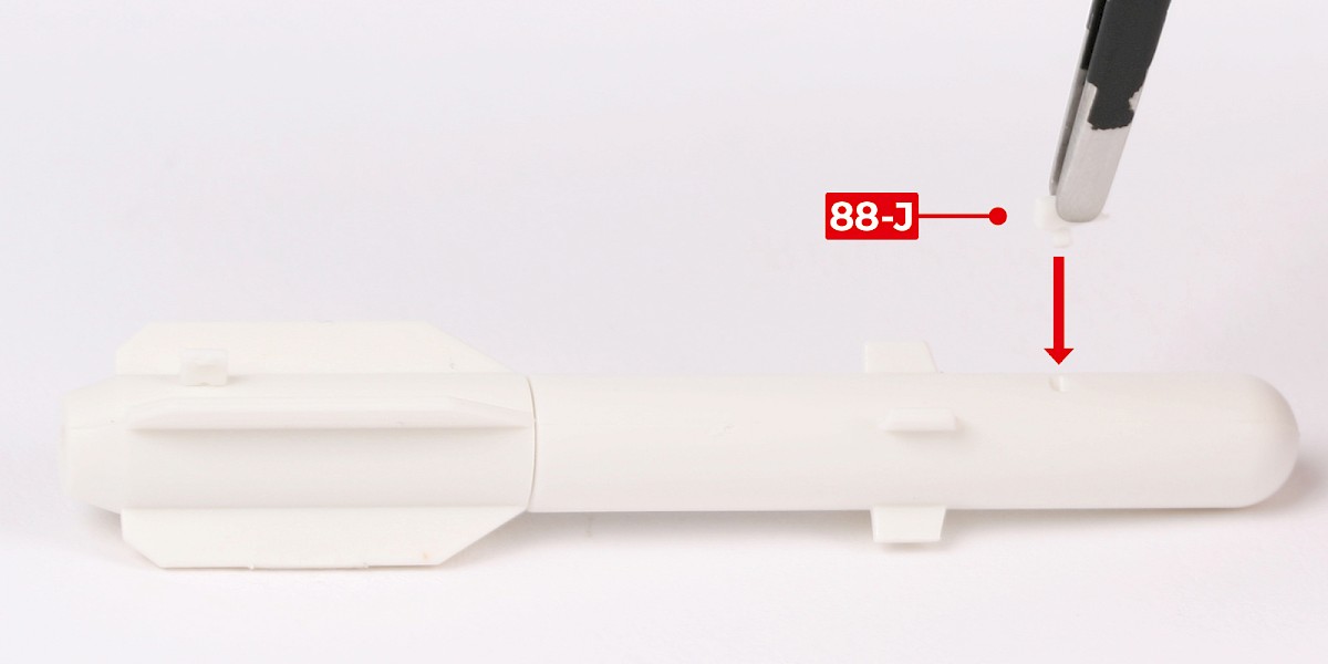
Glue 85-J to the assembly.
Step 3
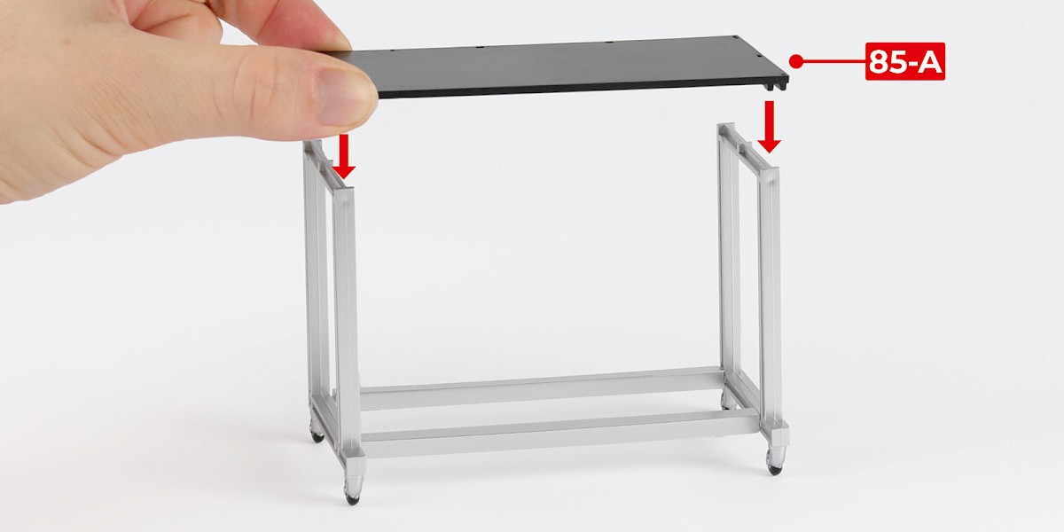
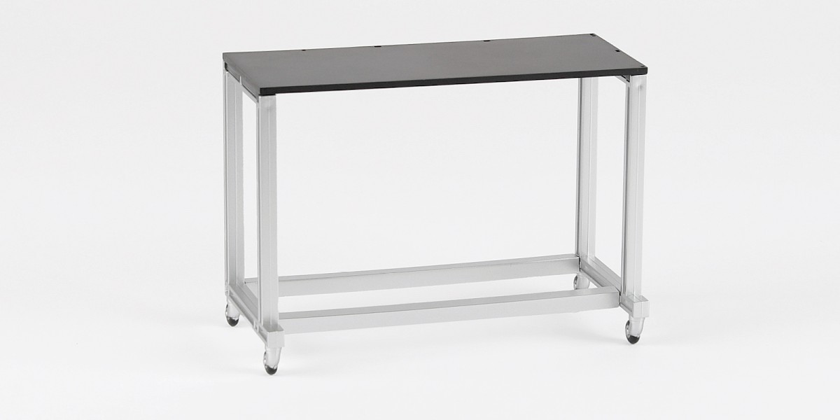
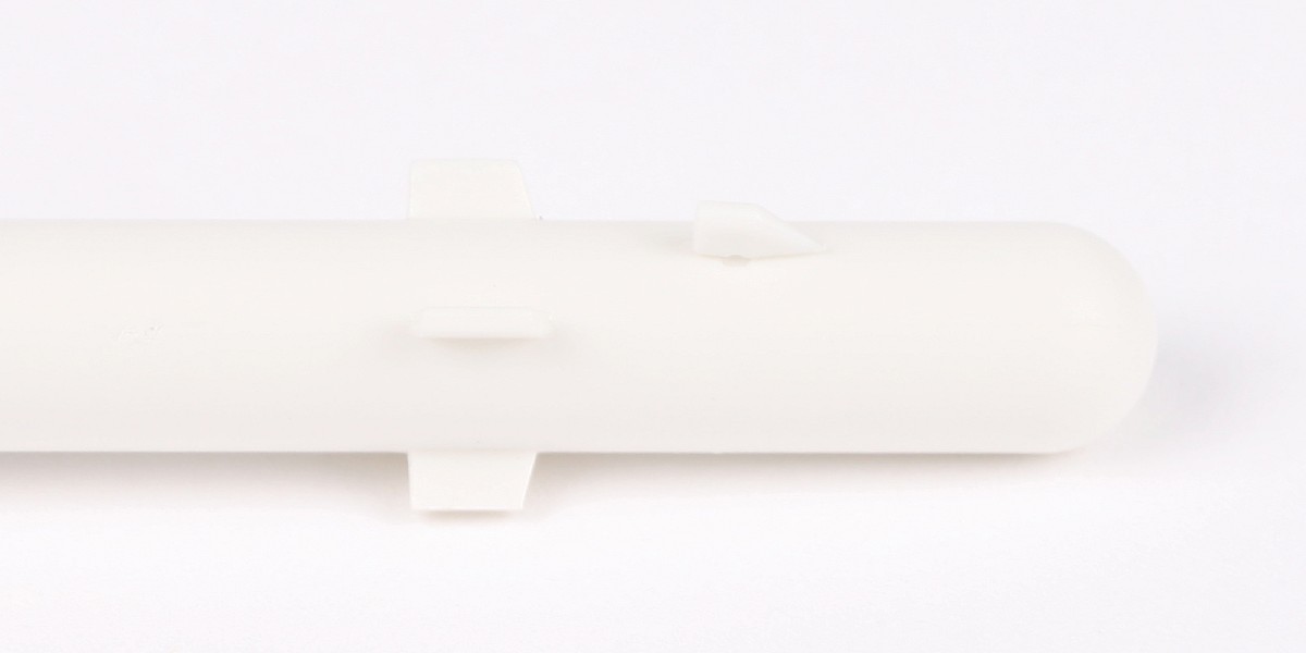
Glue 85-A to the assembly.
Step 4
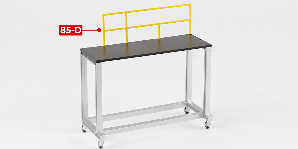
Glue 85-D to the assembly.
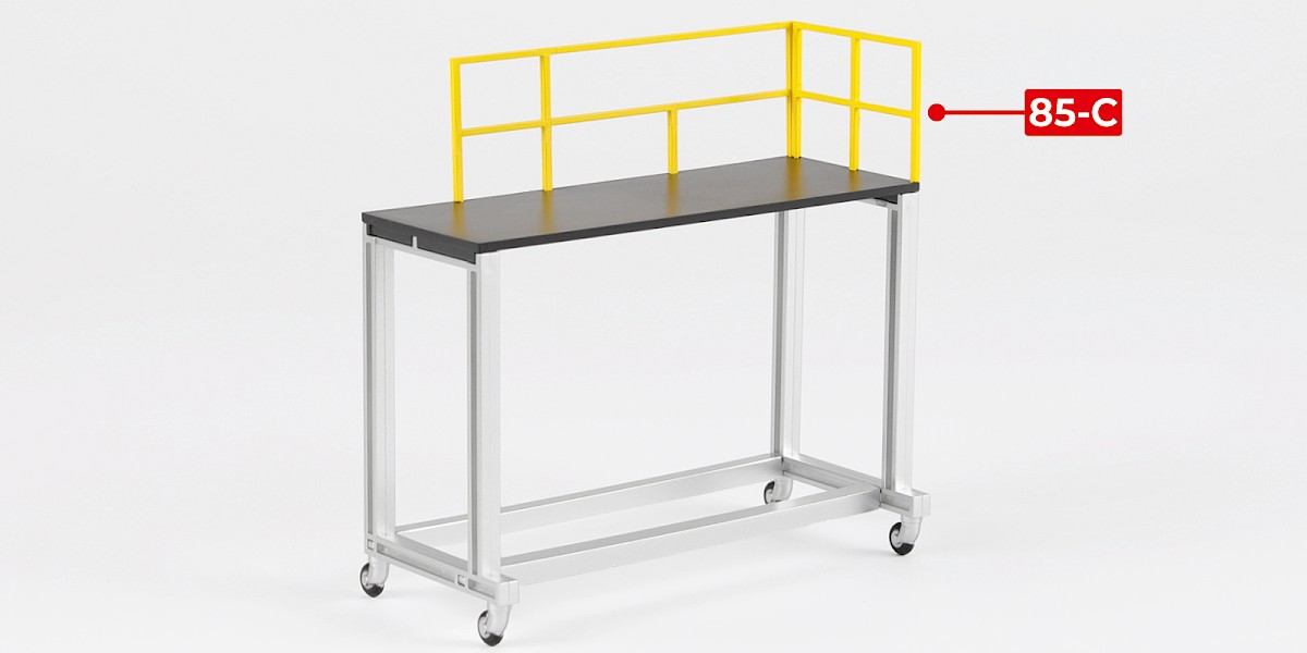
Glue 85-C to the assembly.
Step 5
Glue 85-E to 85-B.
Step 6
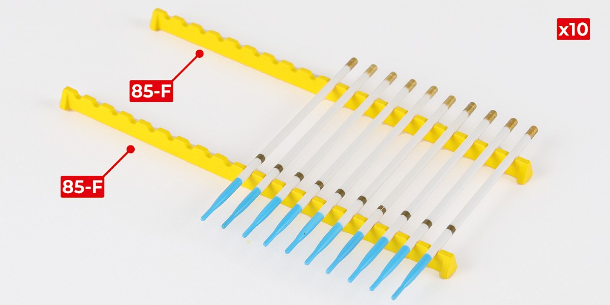
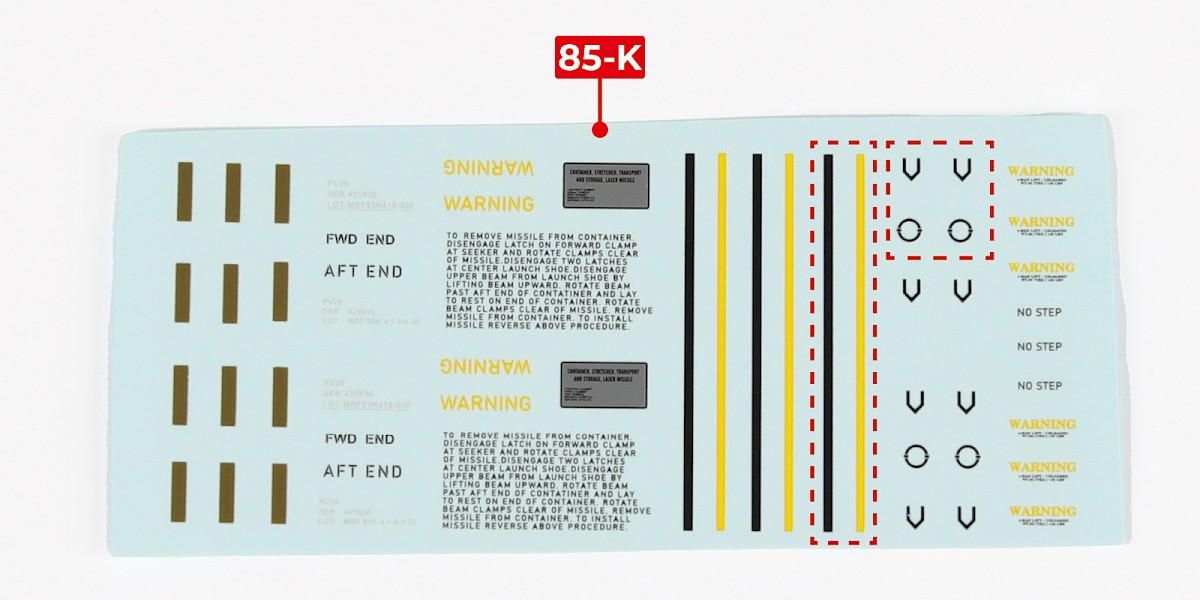
You will now add the decals to a set of rockets.
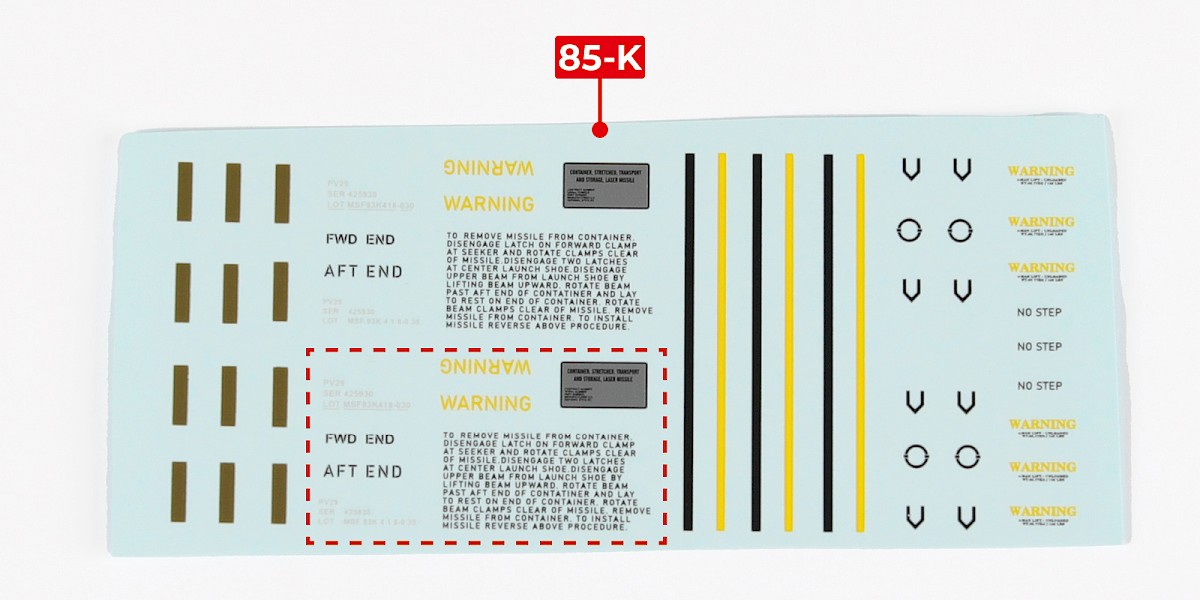
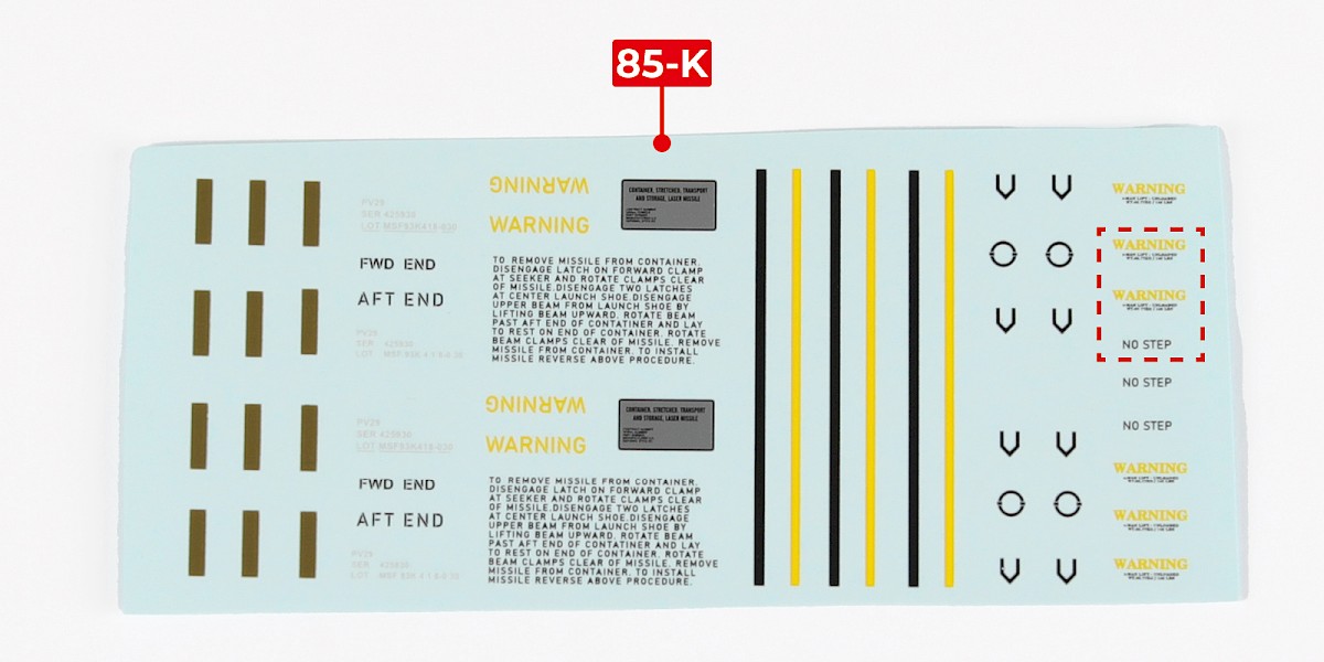
Cut the decals outlined in red from 85-K.
Step 7
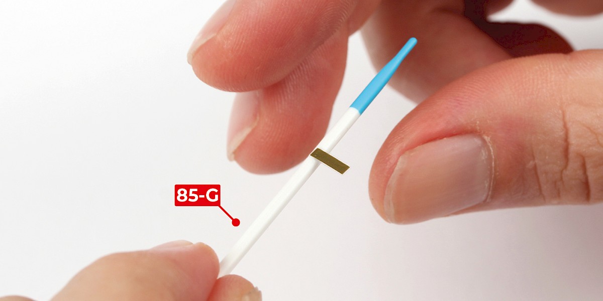
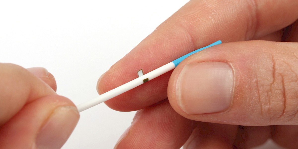
Apply a decal to 85-G. Use the rockets from previous stages as a reference when positioning the decals.
Step 8
Repeat to make 10 rockets.
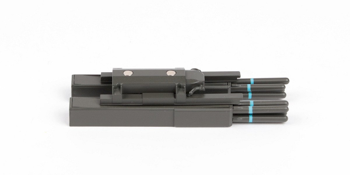
The rockets can be displayed on the storage racks – parts 85-F.
STAGE COMPLETE
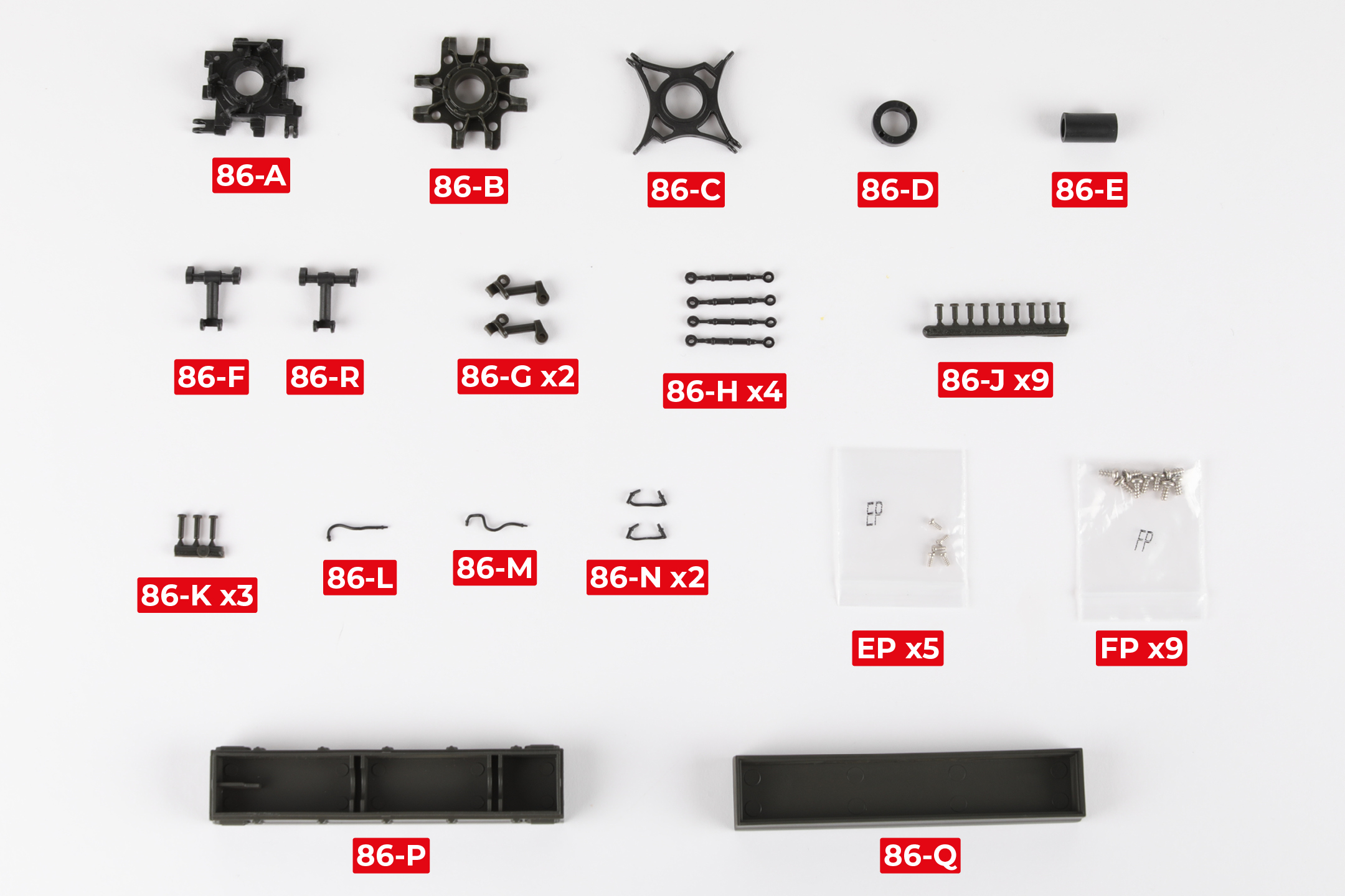
PARTS LIST
| 86-A | 86-G x2 | 86-N x2 |
| 86-B | 86-H x4 | 86-P |
| 86-C | 86-J x9 | 86-Q |
| 86-D | 86-K x3 | 86-R |
| 86-E | 86-L | FP x9 |
| 86-F | 86-M | EP x5 |
Step 1
Fit 86-F and 86-R to 86-A. Make sure the parts are in the orientation shown.
Note that 86-R is slightly wider than 86-F, as shown by the blue line.
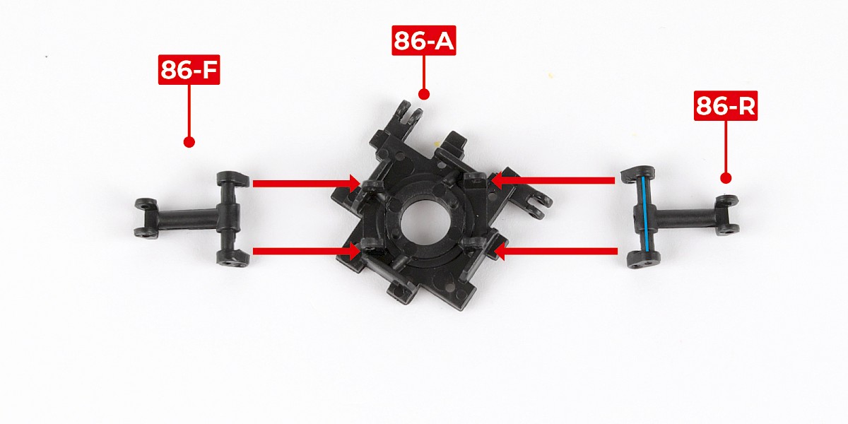
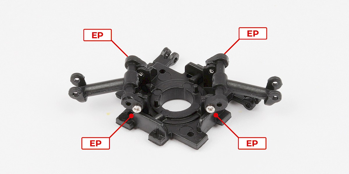
Step 2
Secure with 4x EP.
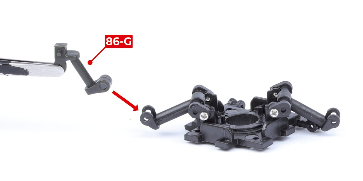
Step 3
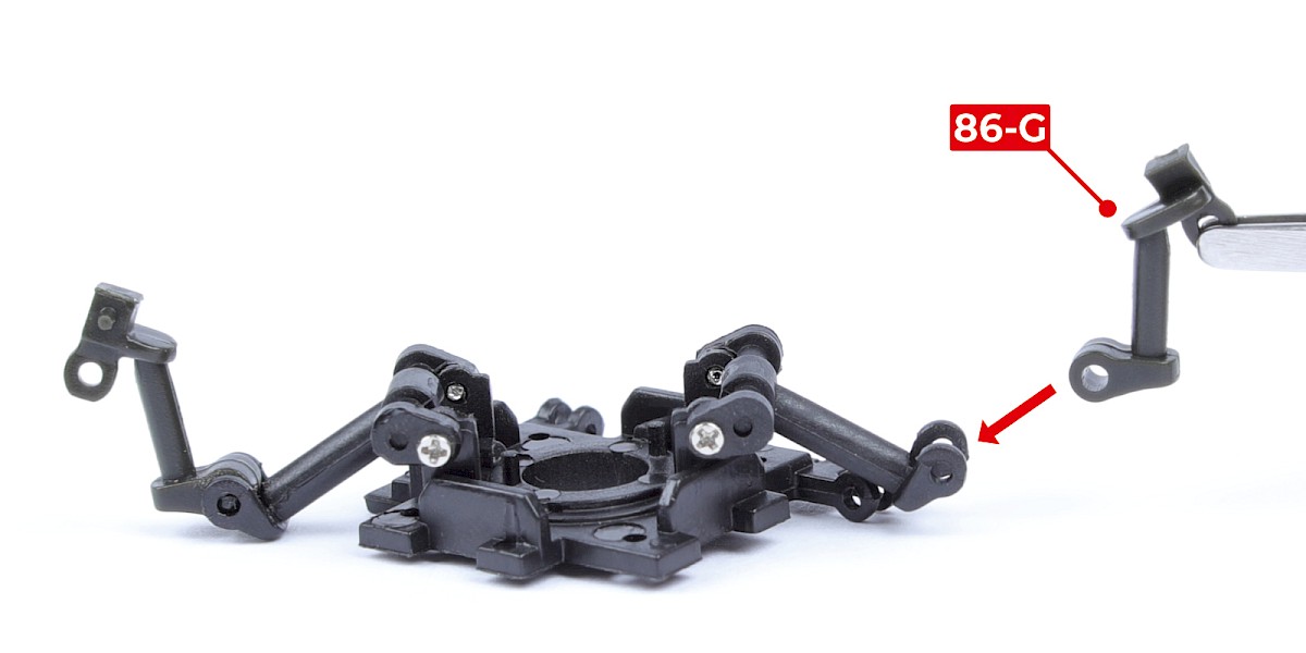
Fit 86-G to the assembly. Make sure the parts are in the orientation shown.
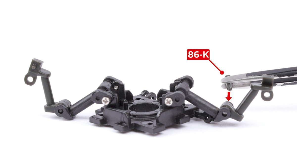
Secure with 86-K.
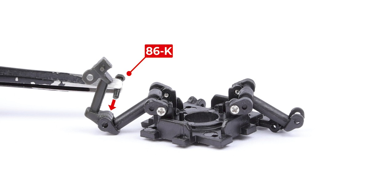
Step 4
Fit 86-G to the other side in the same way.
Secure with 86-K.
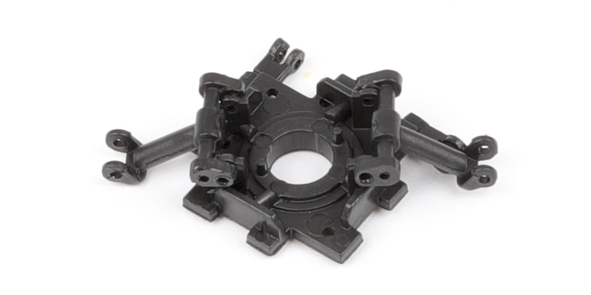
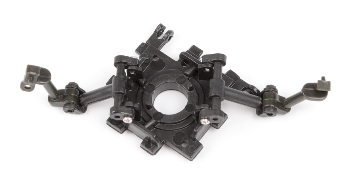
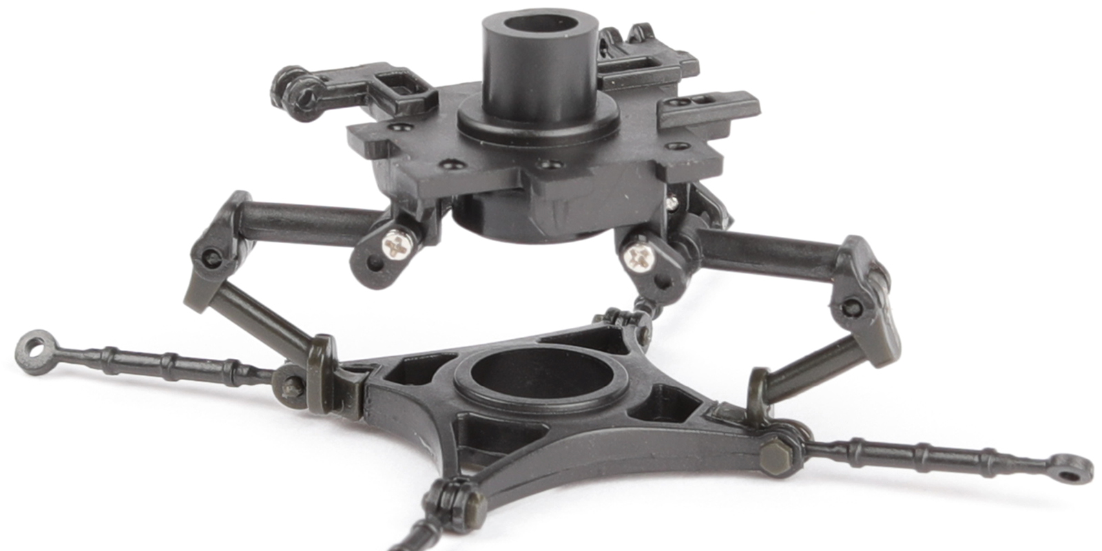
Step 5
The assembly should now look like this.
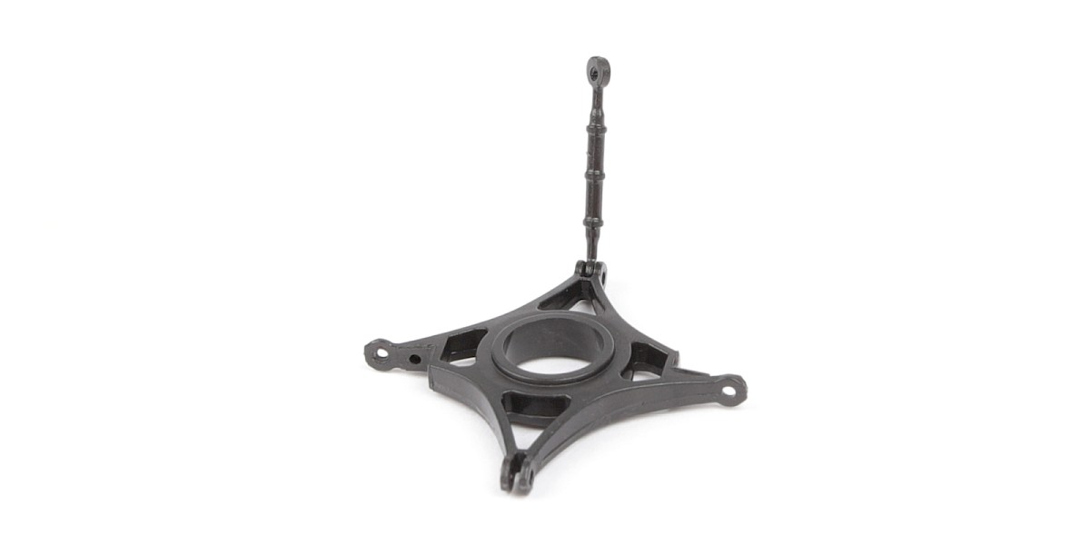
Step 6
Fit 86-H to 86-C. Make sure the parts are in the orientation shown.
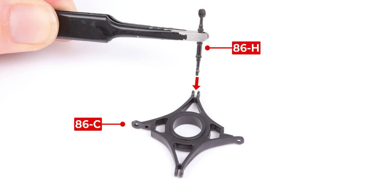
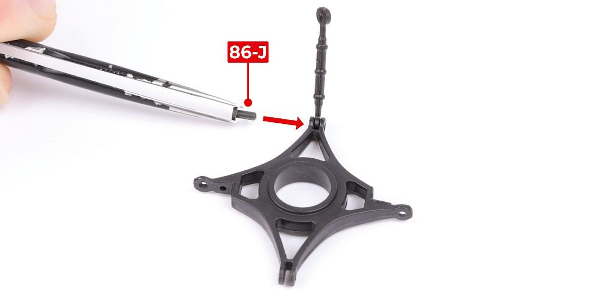
Step 7
Secure with 86-J.
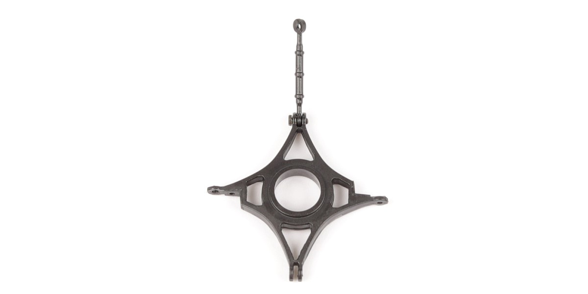
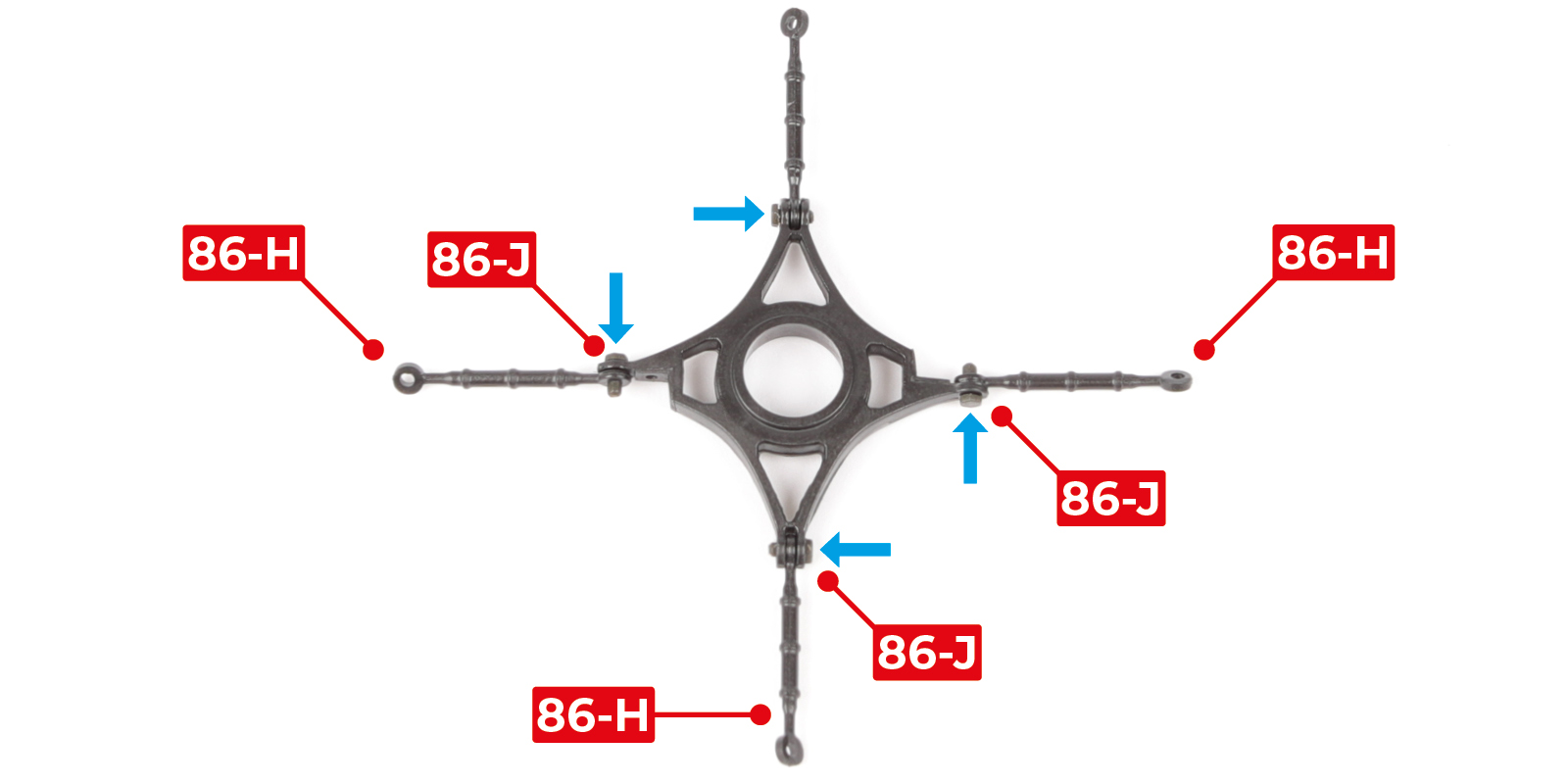
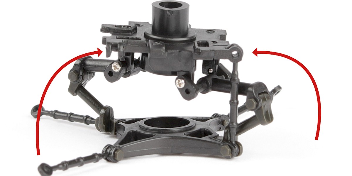
Step 8
Fit three more 86-H to the assembly and secure each 86-H with an 86-J. Press 86-J into the parts in the direction shown by the blue arrows.
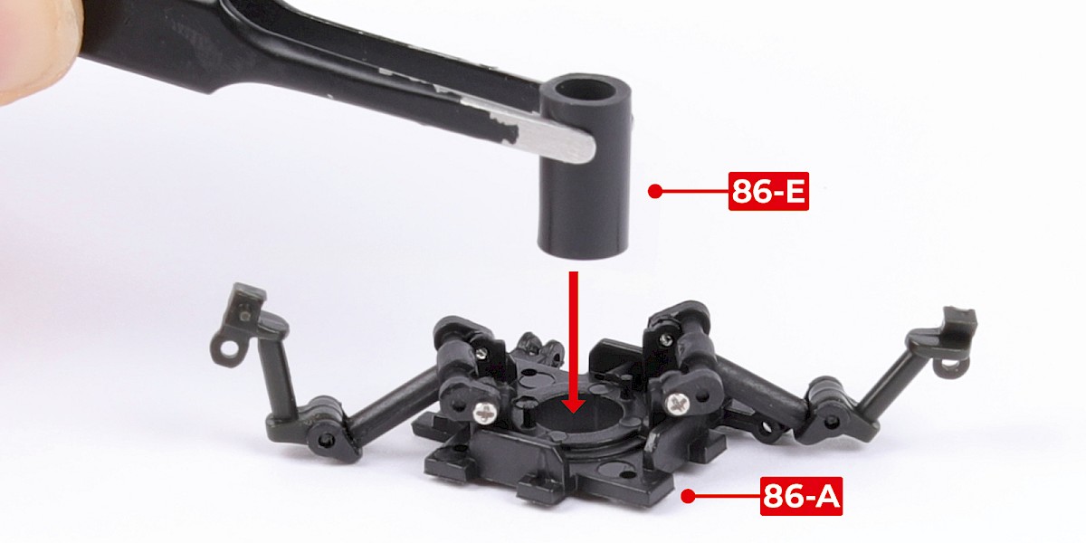
Step 9
Fit 86-E into 86-A.
Fit 86-D over 86-E and onto the pins.
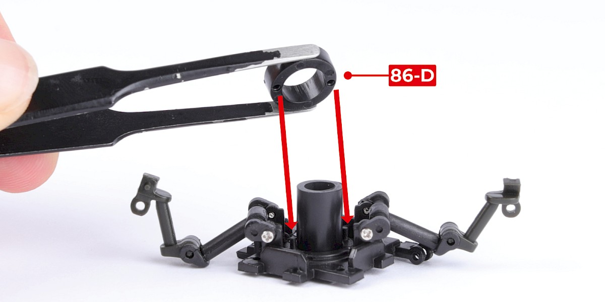
Step 10
Push 86-E through until it is flush with 86-D as shown.
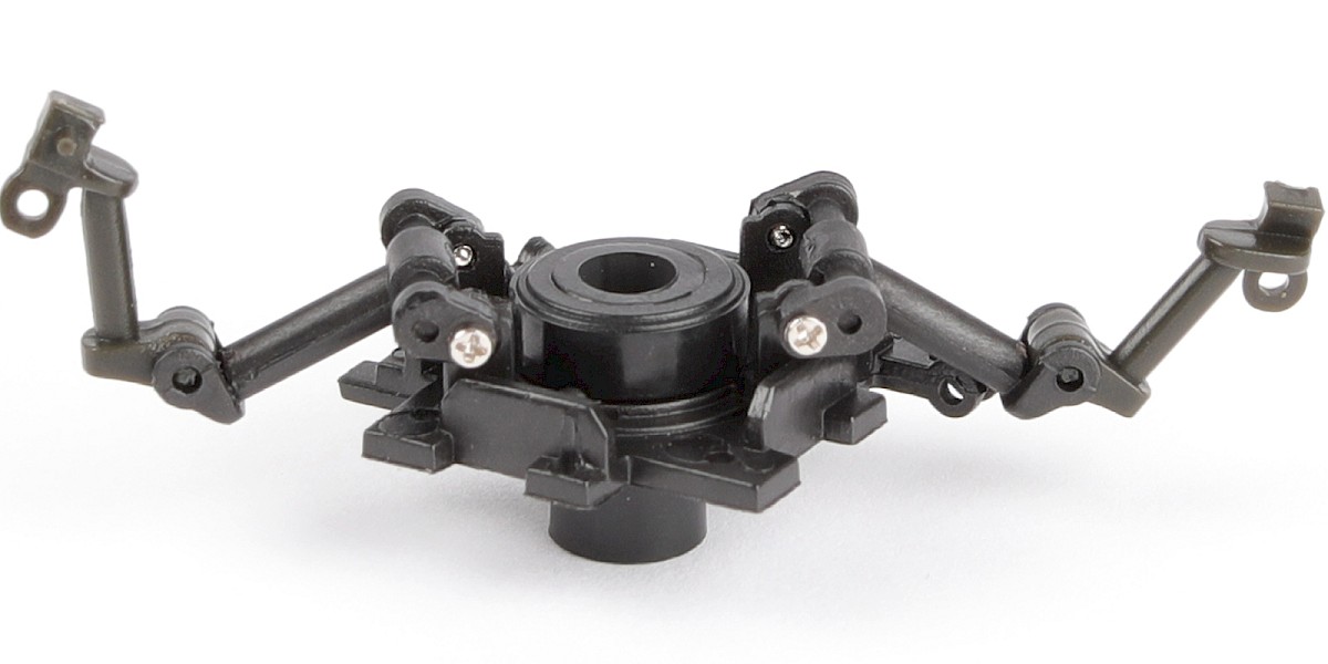
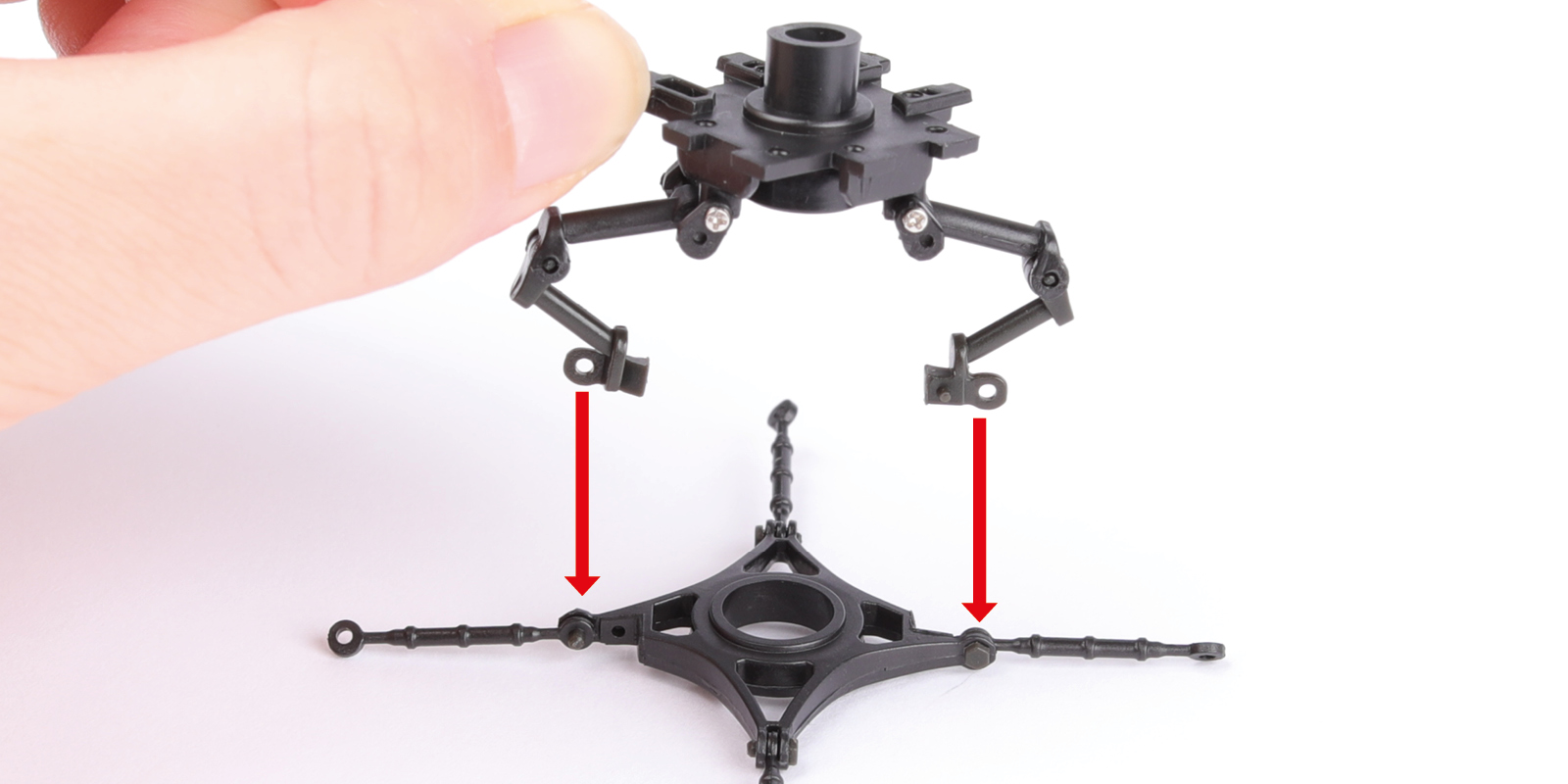
Step 11
Turn the assembly over and fit it to the other assembly from step 8.
You may want to glue the parts together. Do not apply glue to the bolts (86-J steps 7 & 8).
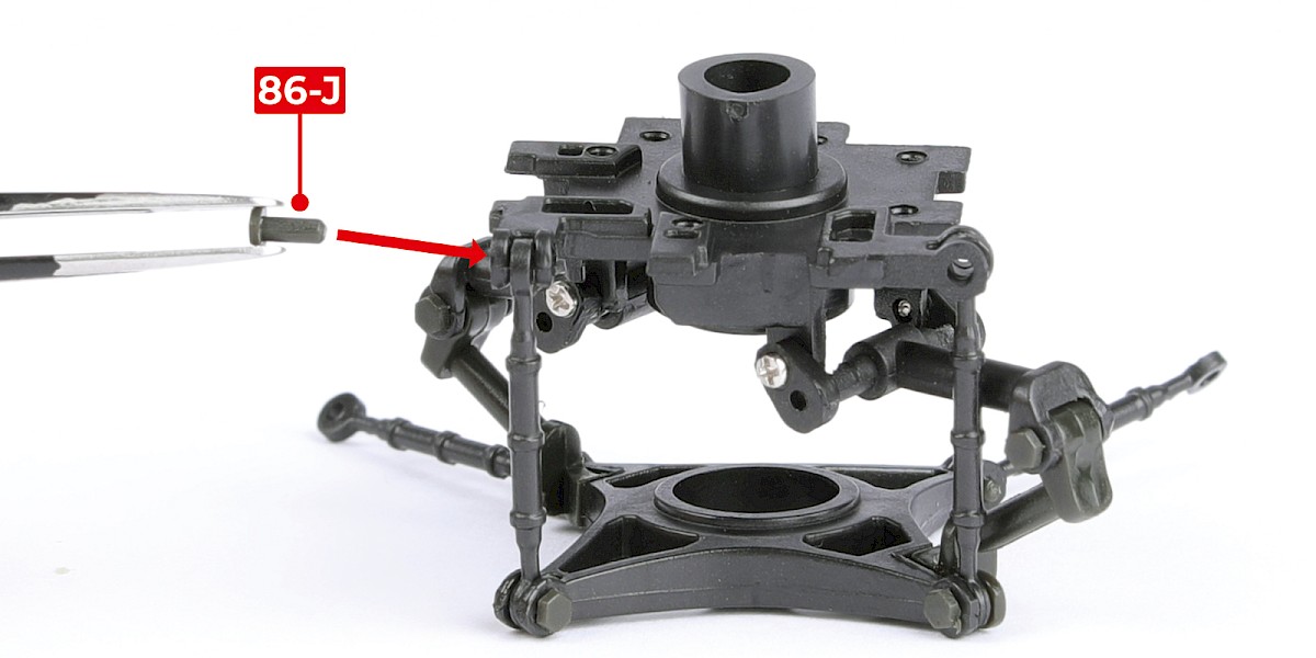
Step 12
Fit the control rods (86-H) in place as shown.
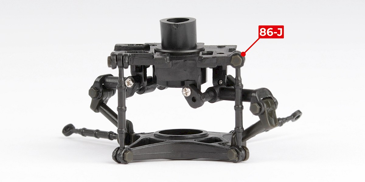
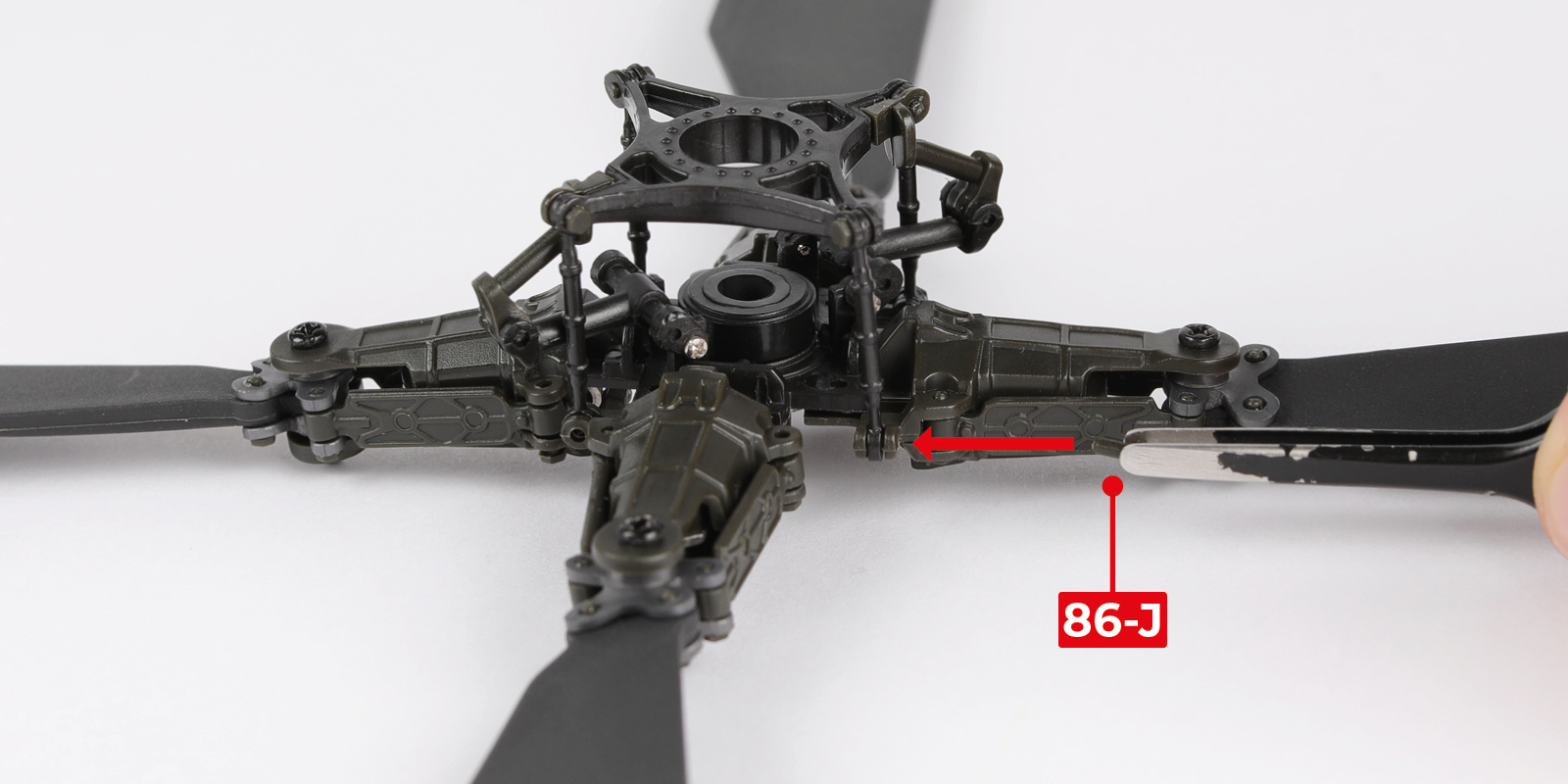
Step 13
Secure the control rods with 2x 86-J.
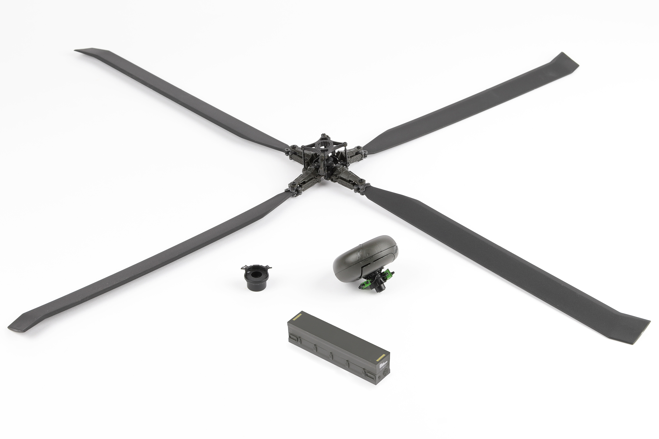
Step 14
Place the rotor blade assembly (stage 17) on your work surface in the orientation shown.
Step 15
Fit the assembled parts onto the rotor blades. Fit the remaining two control rods in place as shown.
Step 16
Secure the control rods with 2x 86-J.
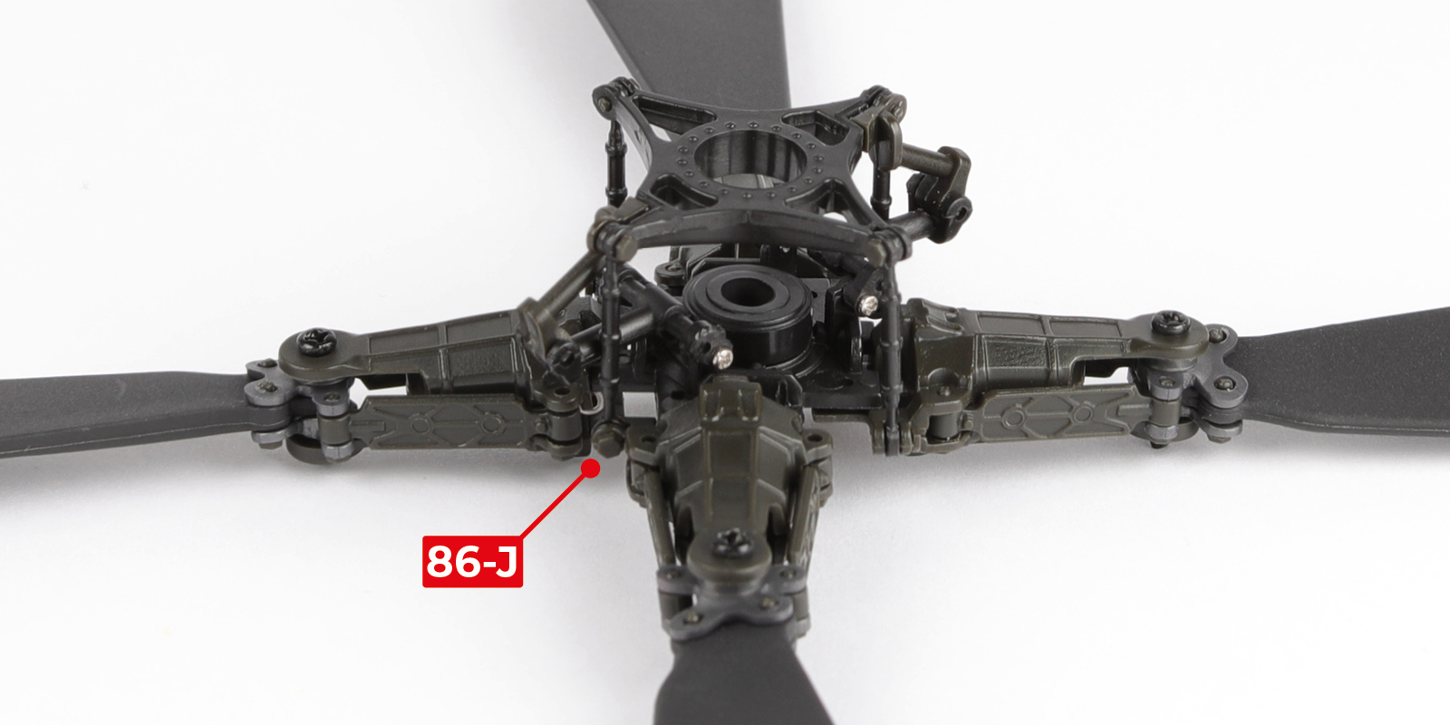
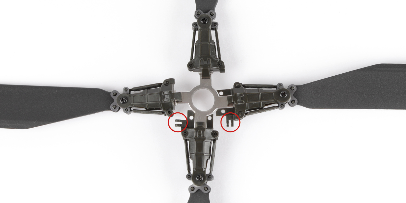
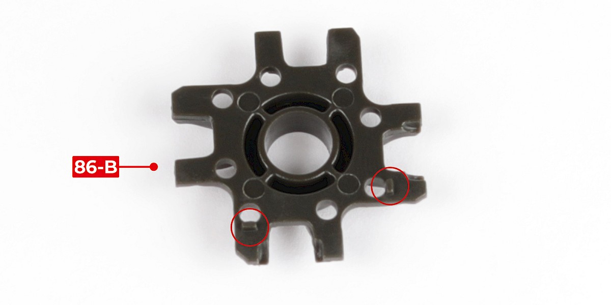
Step 17
Locate the two pins on 86-B (circled).
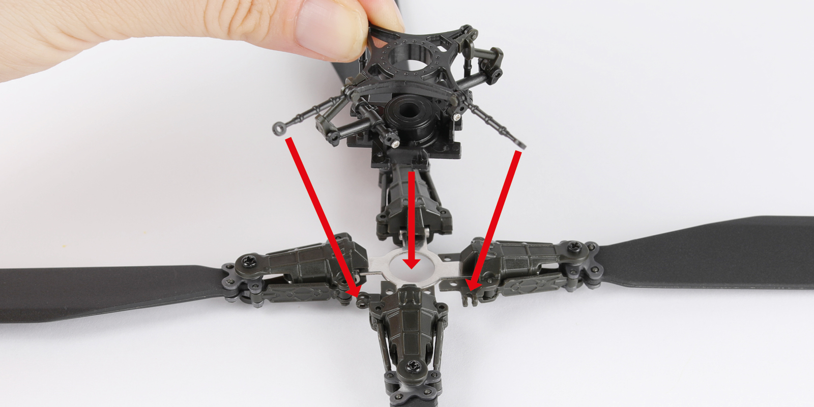
Step 18
Fit 86-B to the assembly. The two pins fit into the recessed parts as indicated by the arrows.
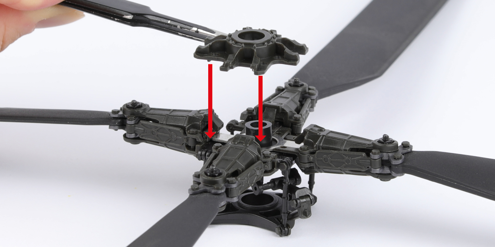
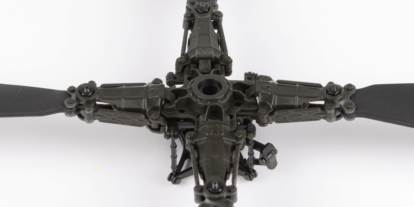
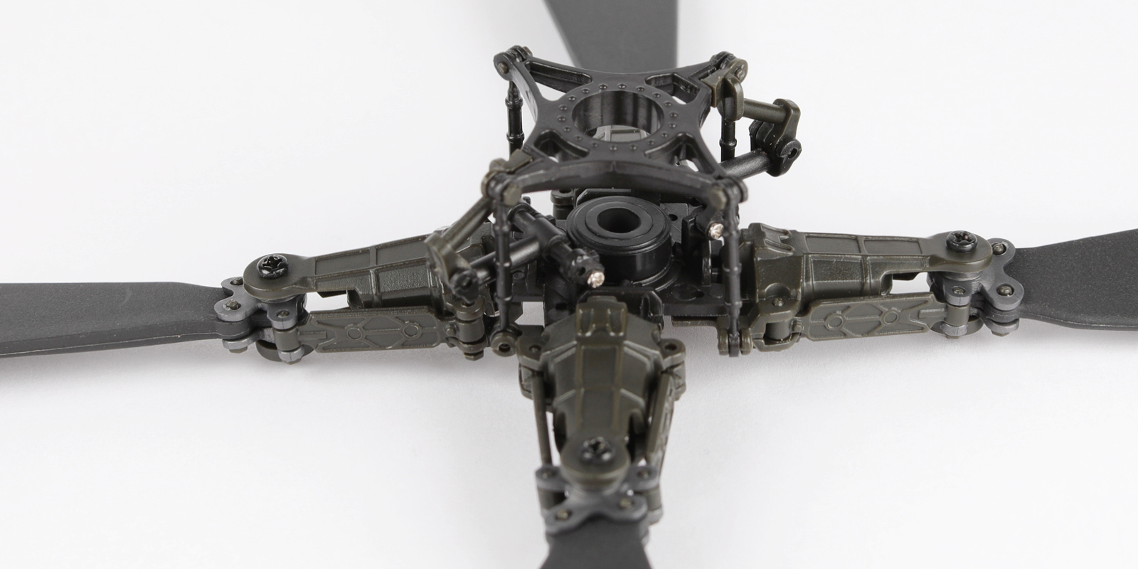
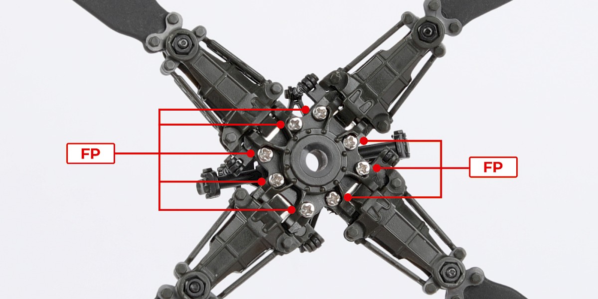
Step 19
Secure with 8x FP.
Step 20
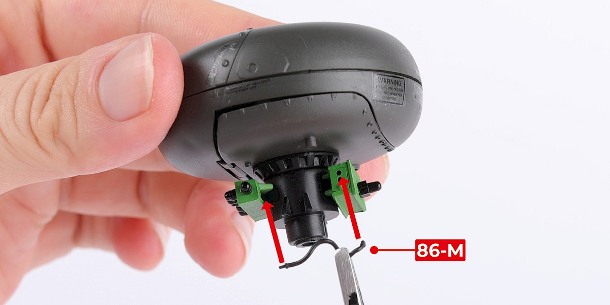
You will now add details to the radar dome and mount.
Glue 86-M to the radar assembly (stage 18).
Step 21
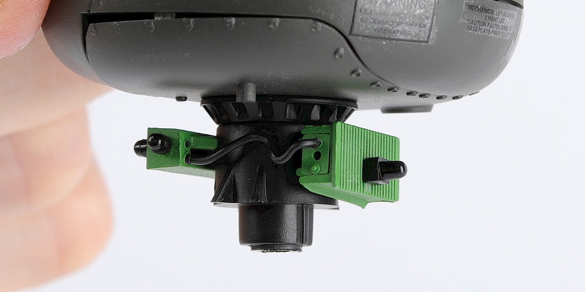
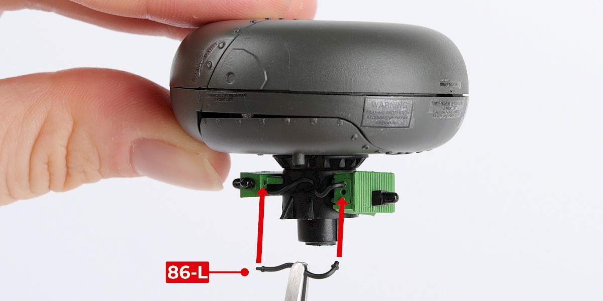
Glue 86-L to the assembly.
Part 86-L should cross underneath 86-M at the point indicated by the circle.
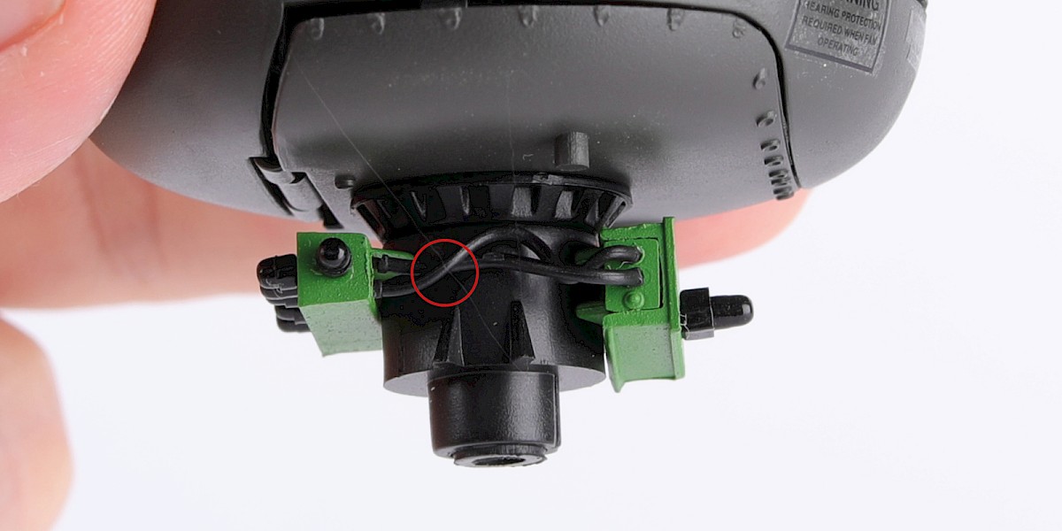
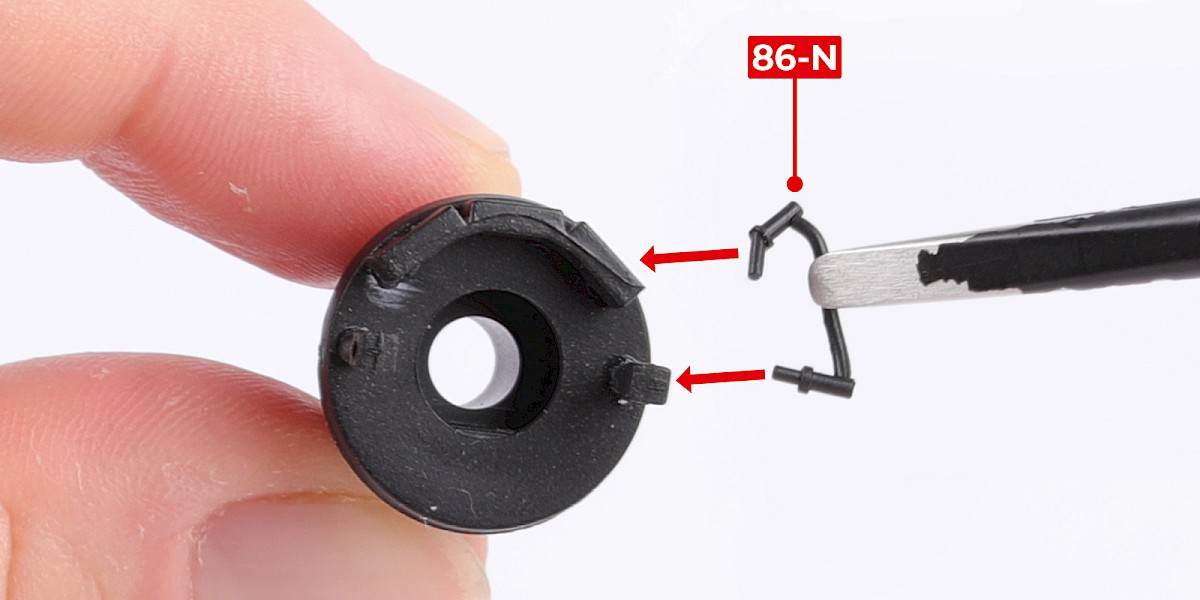
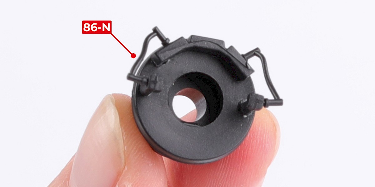
Step 22
Glue 86-N to each side of the radar mount (stage 18).
Step 23
You will now build a missile crate.
Cut the decals outlined in red from 85-K.
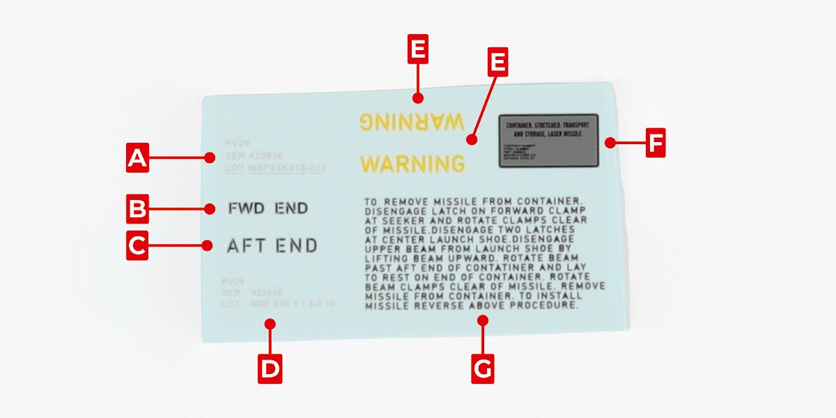
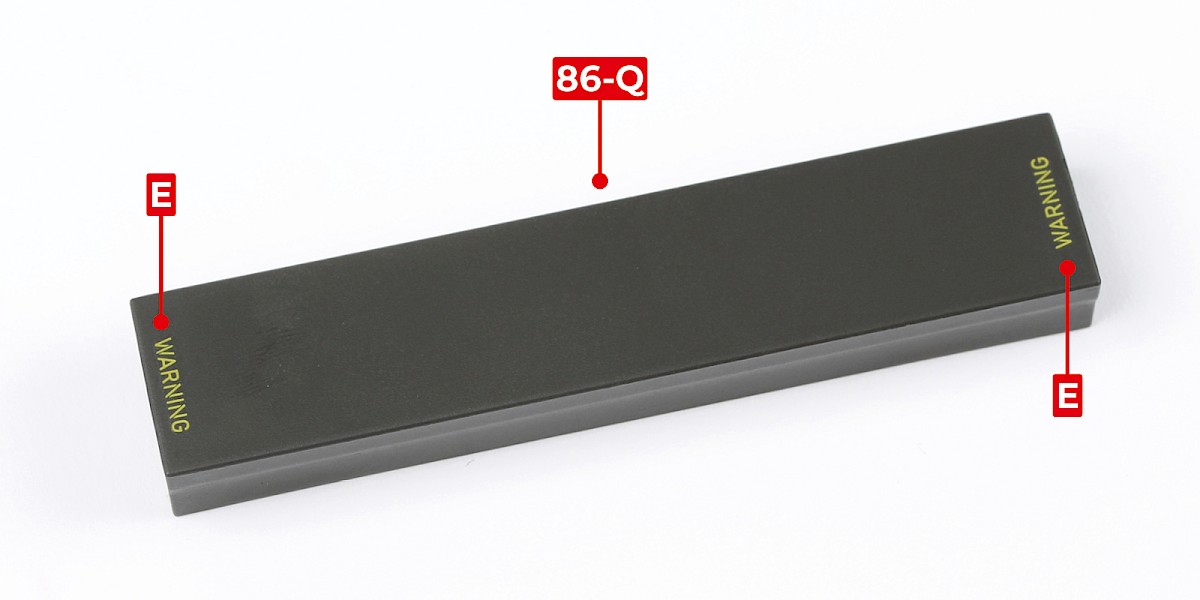
Step 24
Apply the two decals labelled E to 86-Q.
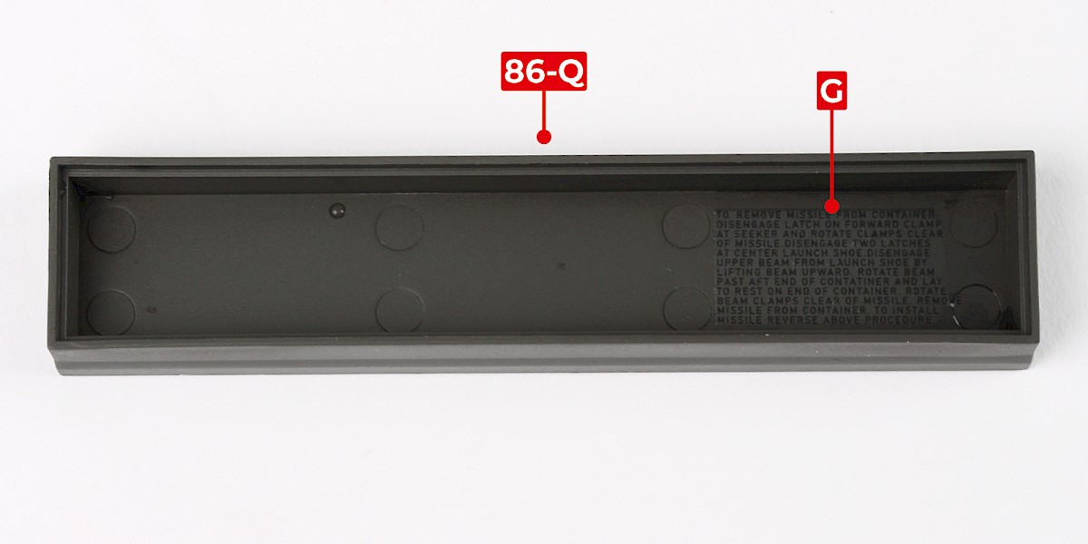
Apply decal G to the inside of 86-Q.
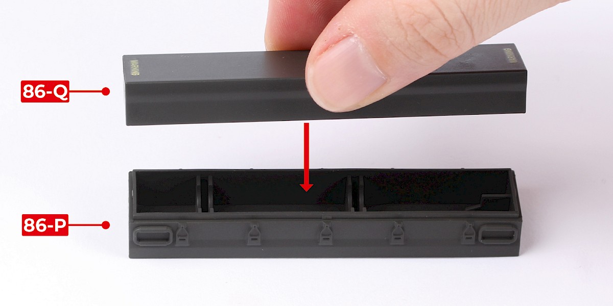
Step 25
Press 86-Q onto 86-P.
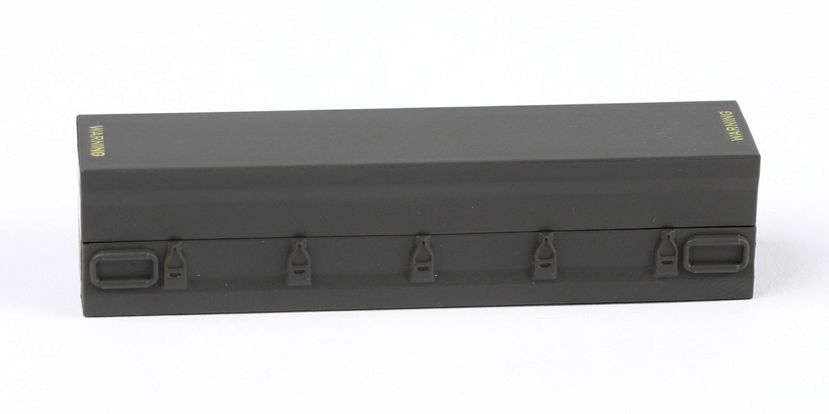
Step 26
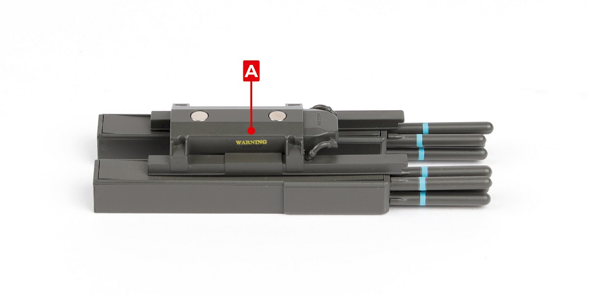
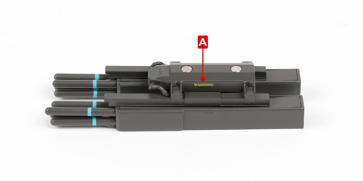
Apply decals A, B, C, D and F to the ends of the missile crate.
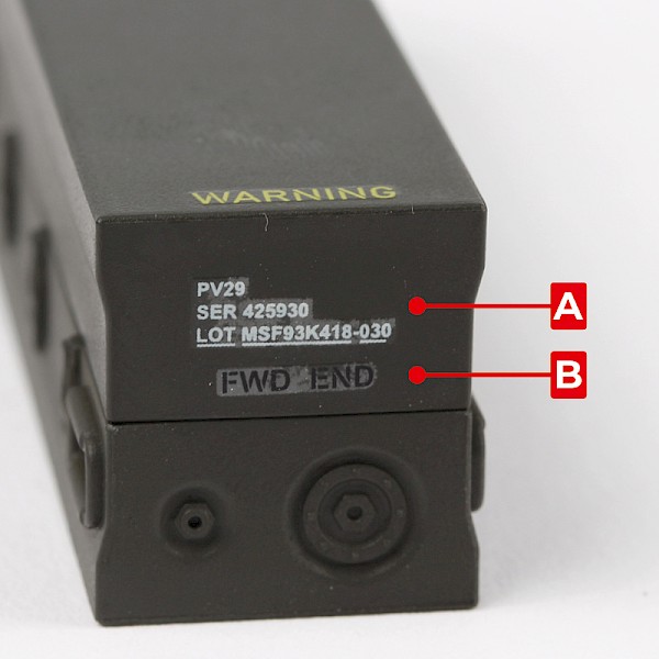
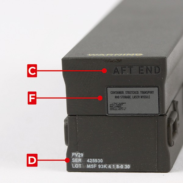
STAGE COMPLETE
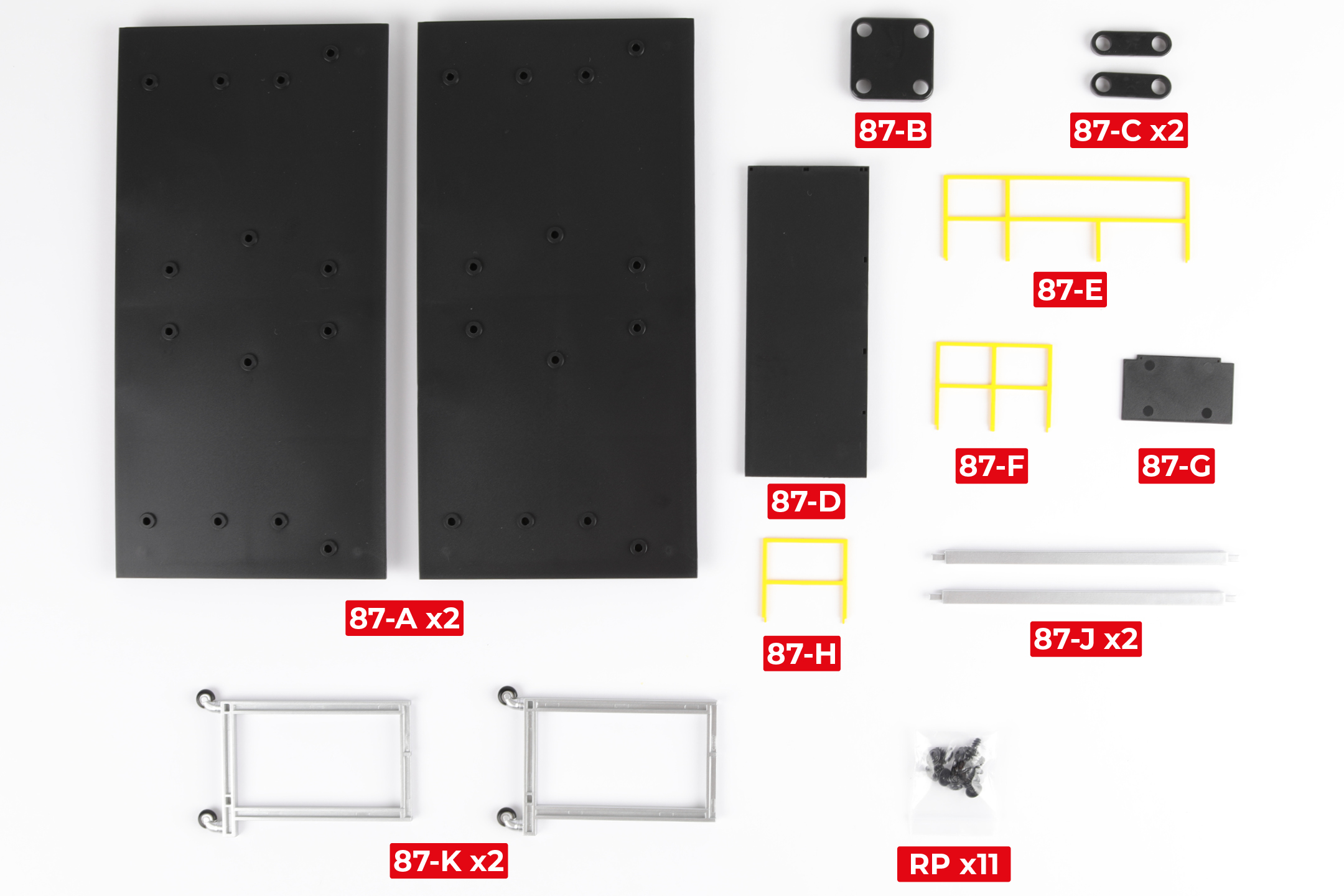
PARTS LIST
| 87-A x2 | 87-G |
| 87-B | 87-H |
| 87-C x2 | 87-J x2 |
| 87-D | 87-K x2 |
| 87-E | RP x11 |
| 87-F |
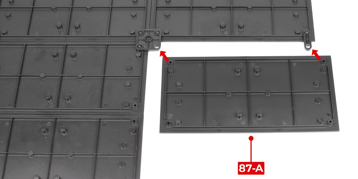
Step 1
Fit 87-A to the bottom of the display base assembly (stage 79).
Make sure the parts are in the orientation shown.
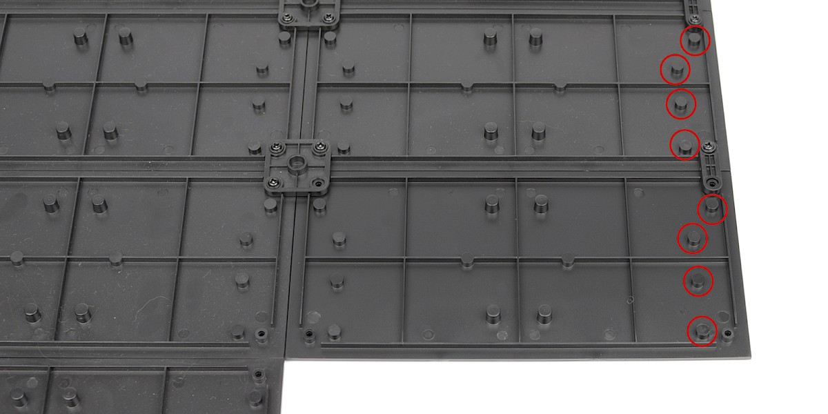
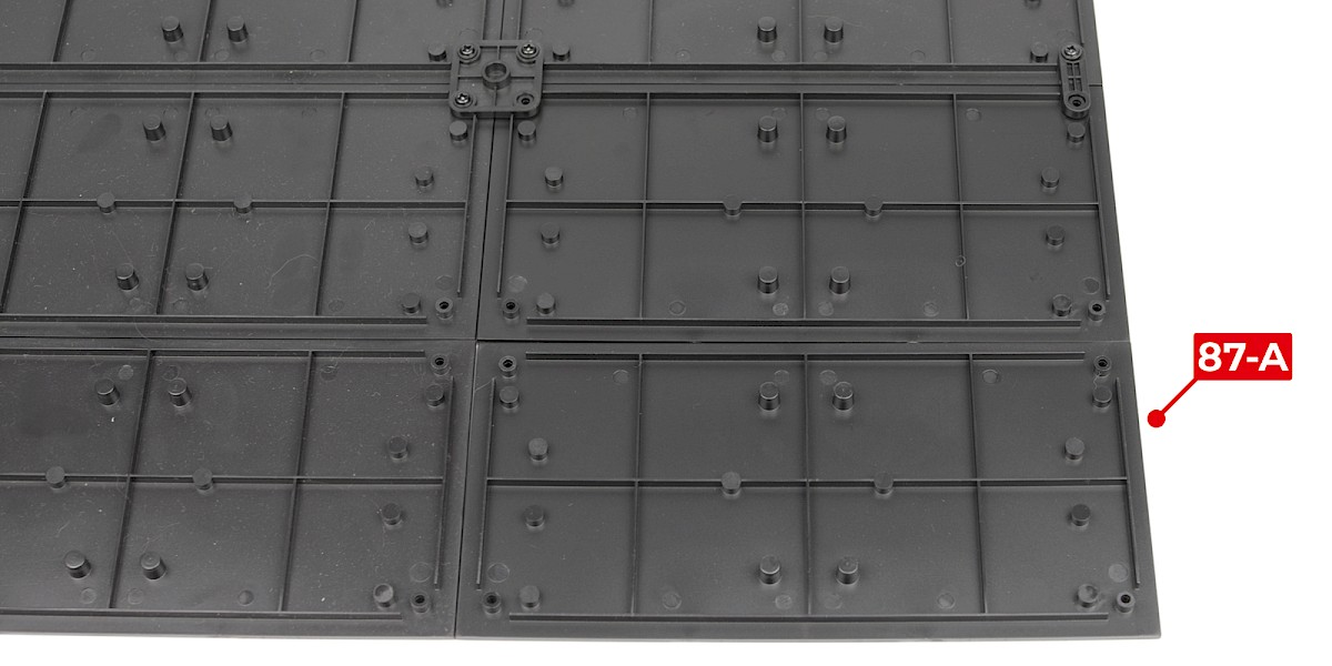
Step 2
Fit the other 87-A.
Step 3
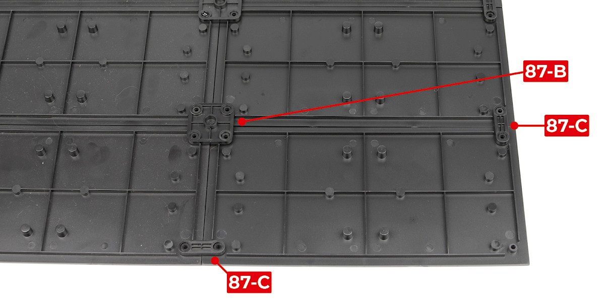
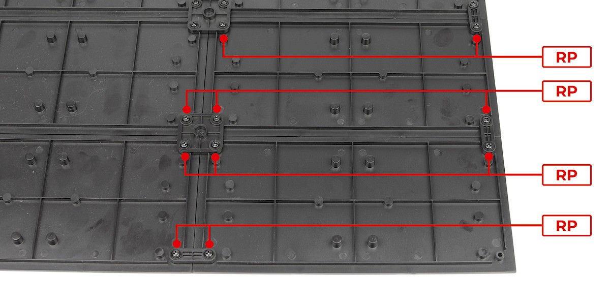
Fit 87-B and the two 87-C pieces to the assembly as shown.
Secure with 10x RP.
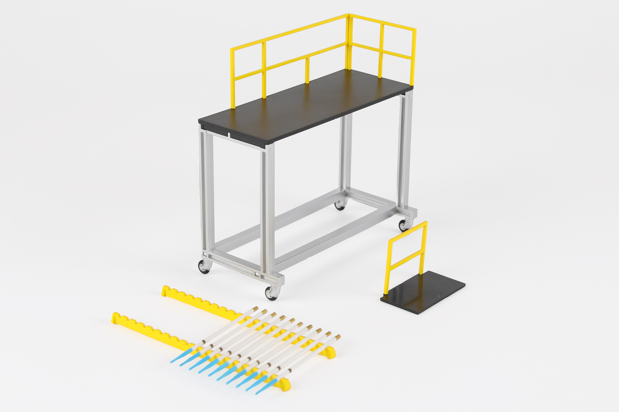
Step 4
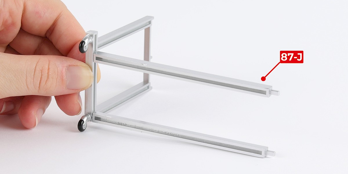
You will now build a mobile platform.
Glue 87-J to 87-K. Do not allow the glue to dry, you may need to adjust the parts.
Glue another 87-J to the assembly.

Step 5
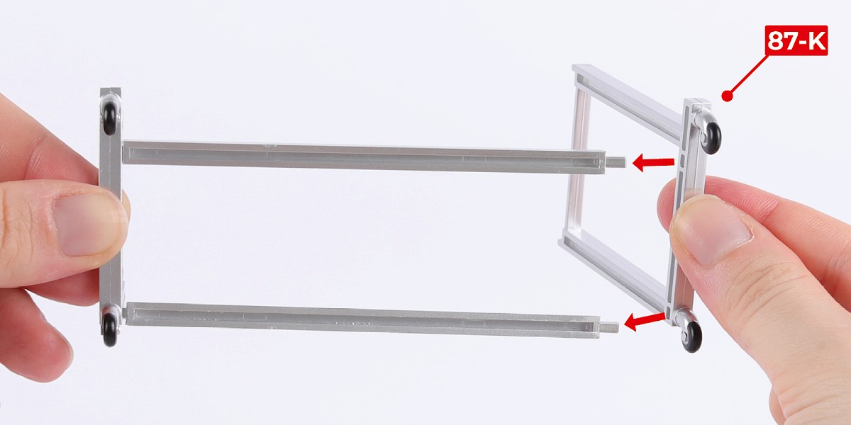
Glue 87-K to the assembly.

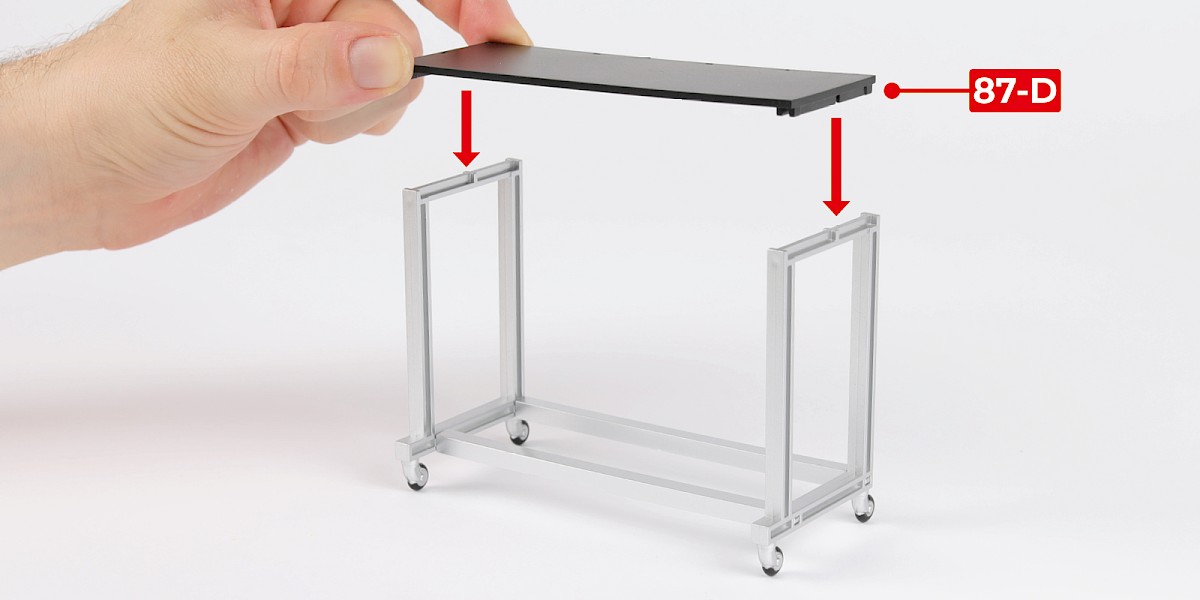
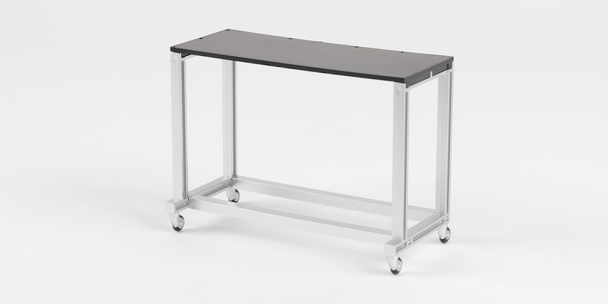
Step 6
Glue 87-D to the assembly.
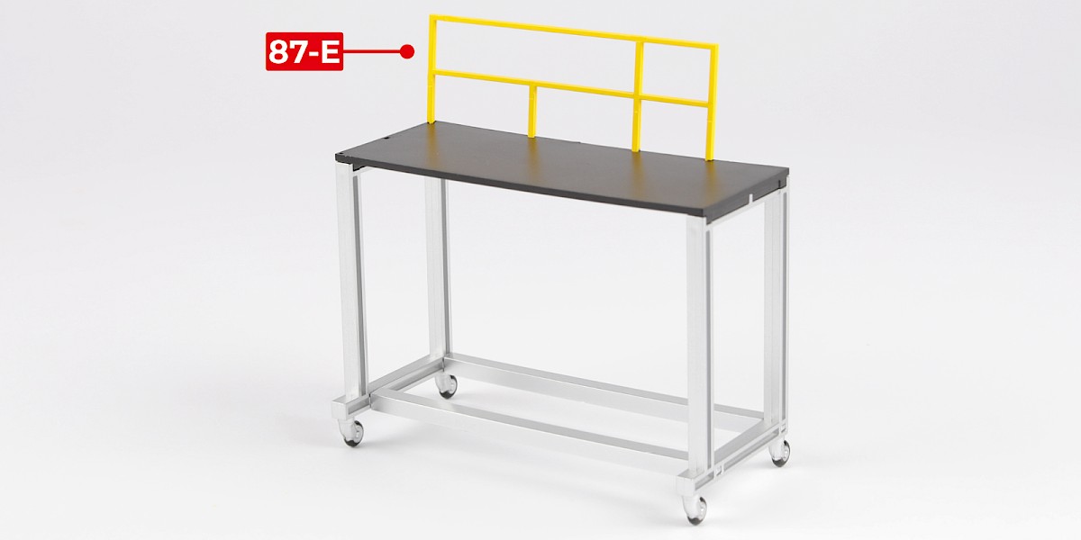
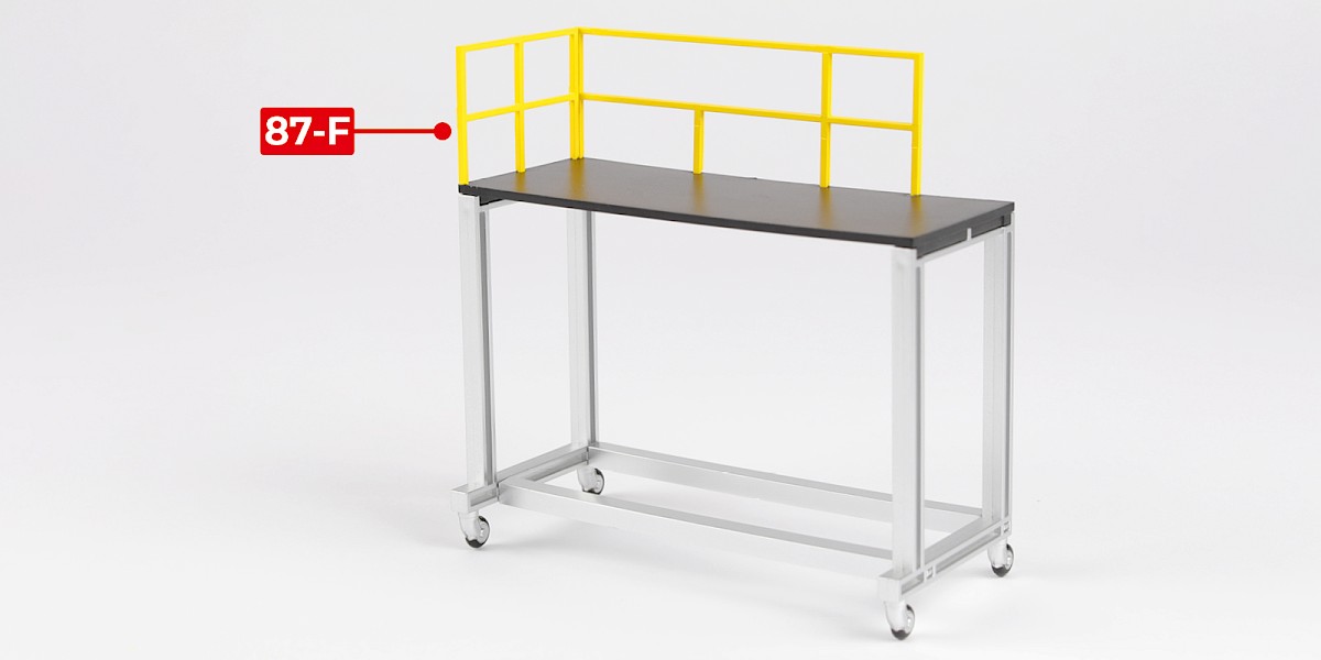
Step 7
Glue 87-E and 87-F to the assembly.
Step 8
Glue 87-H to 87-G.

STAGE COMPLETE
PARTS LIST
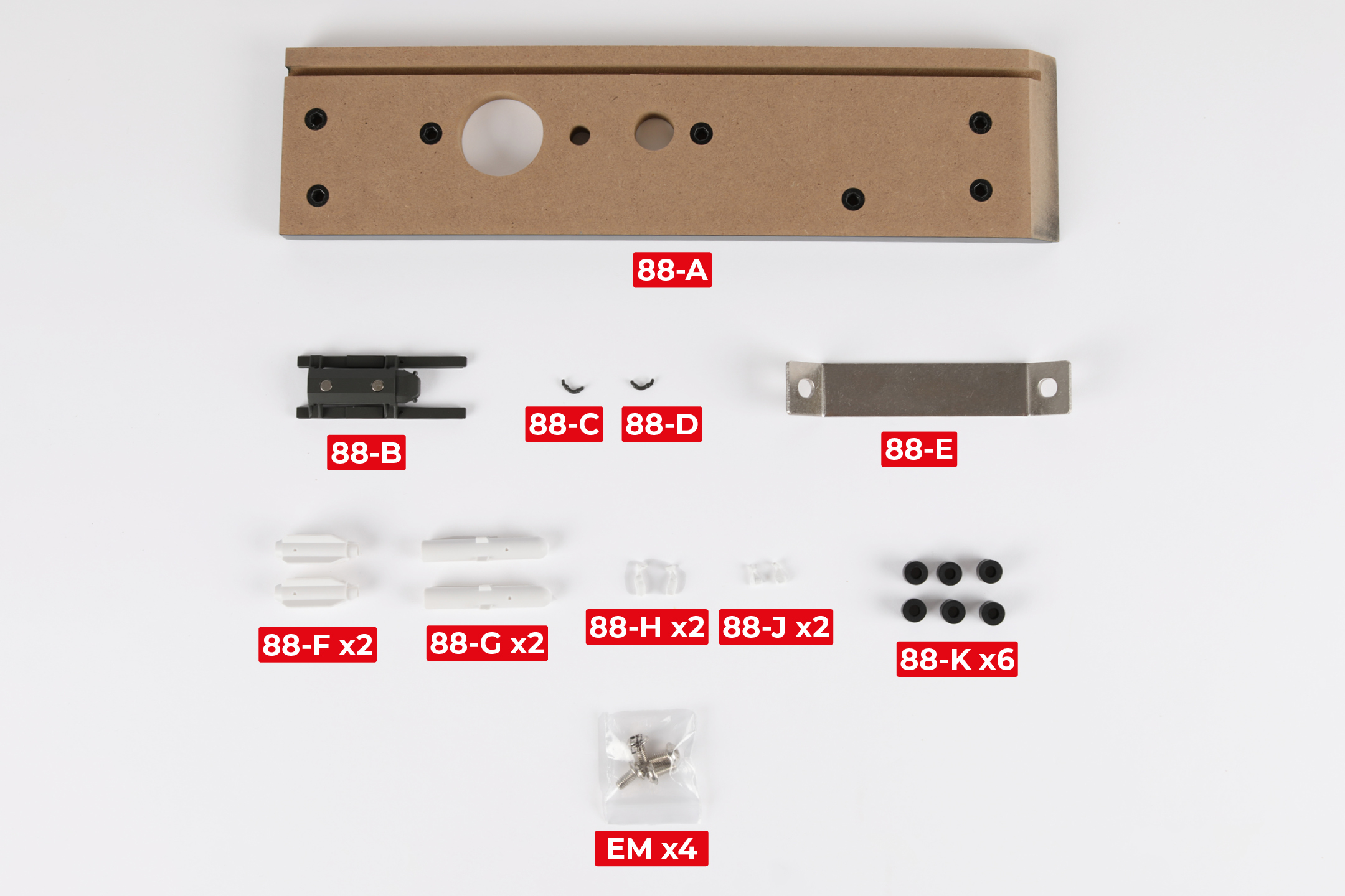
| 88-A | 88-G x2 |
| 88-B | 88-H x2 |
| 88-C | 88-J x2 |
| 88-D | 88-K x6 |
| 88-E | EM x4 |
| 88-F x2 |
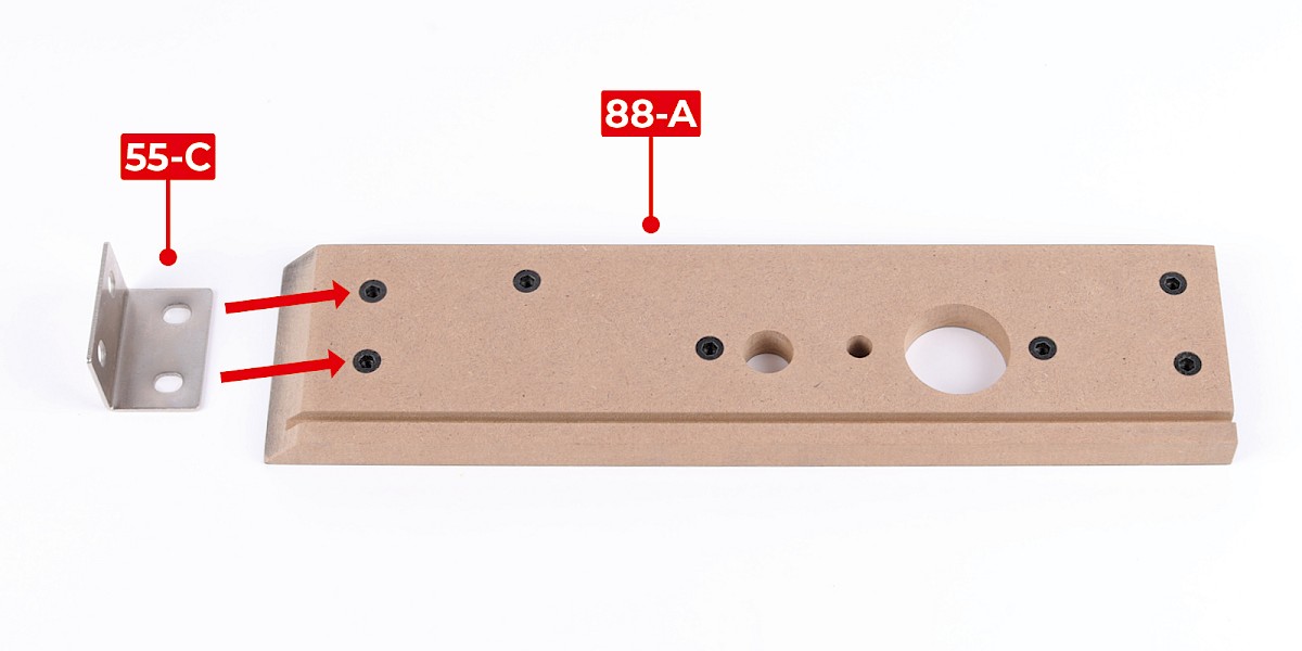
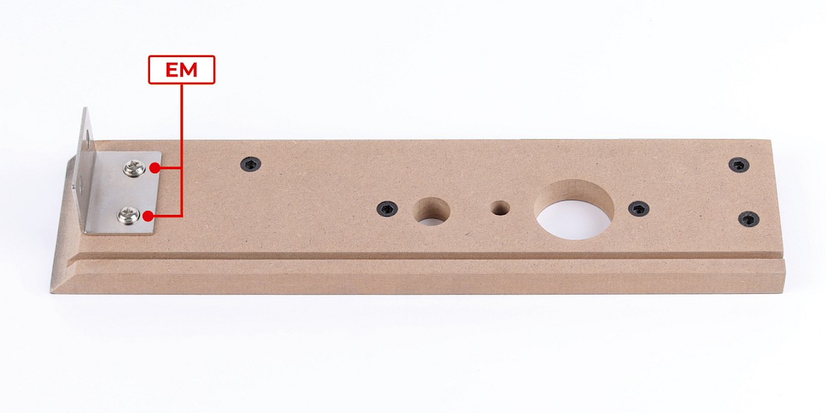
Step 1
Fit 55-C (stage 55) to 88-A.
Secure with 2x EM (supplied with stage 55).
Step 2
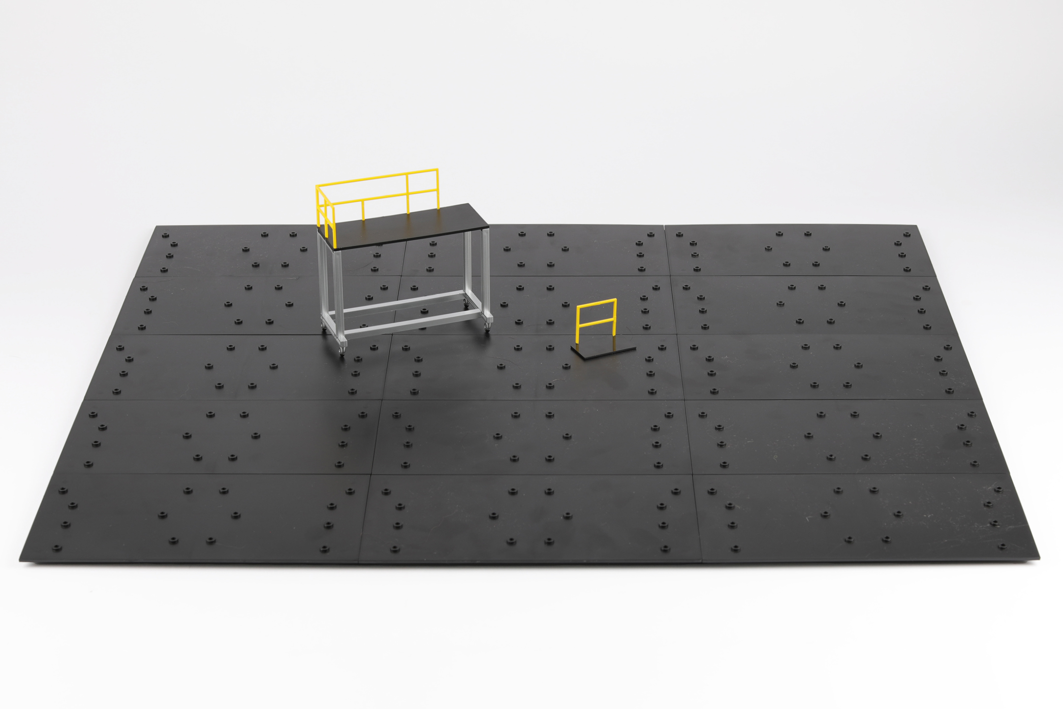
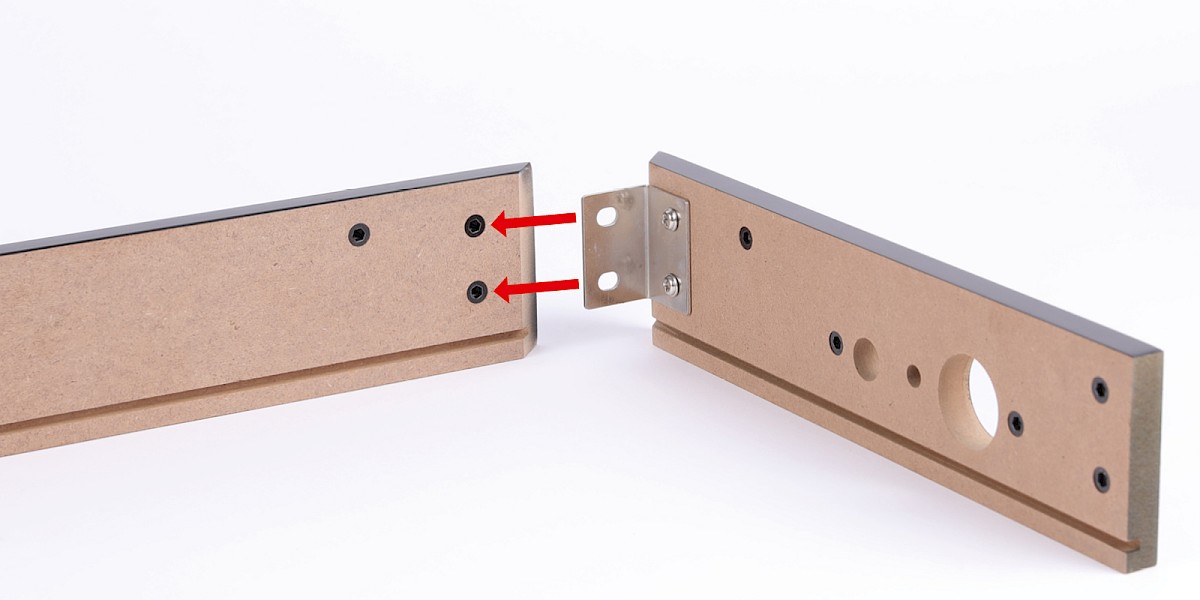
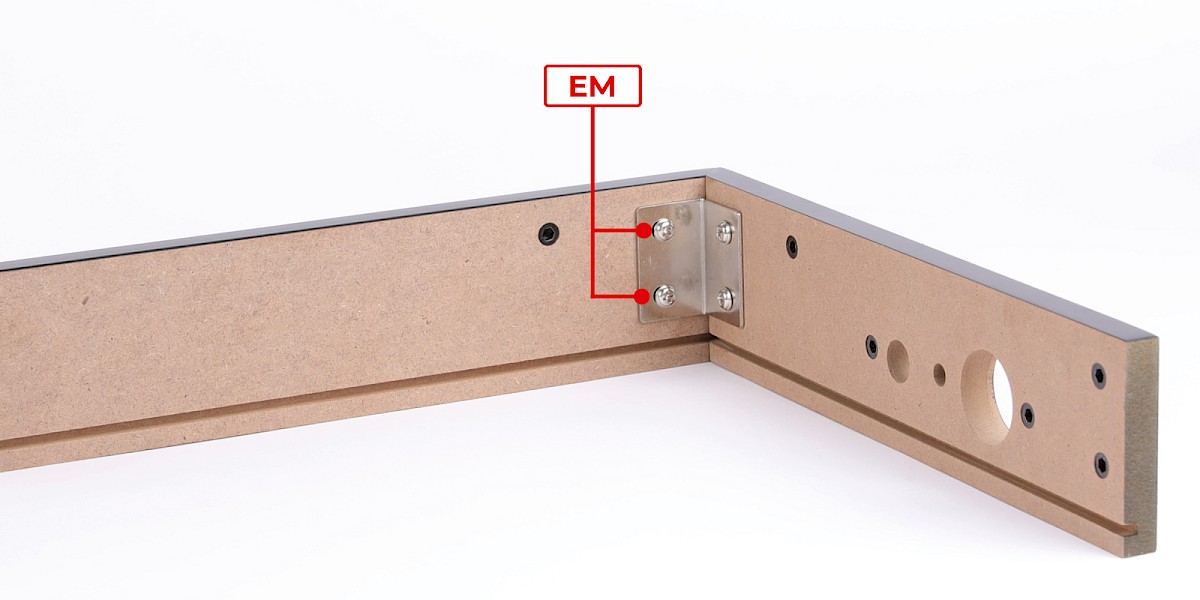
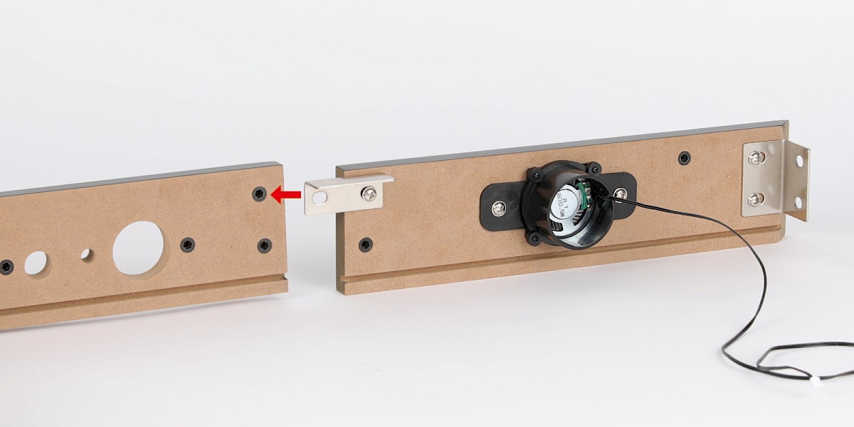
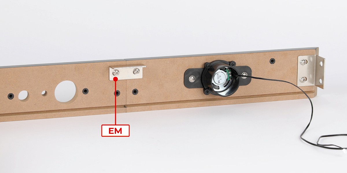
Fit the assembly to the display base frame (stage 84).
Secure with 2x EM.
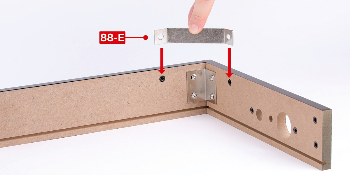
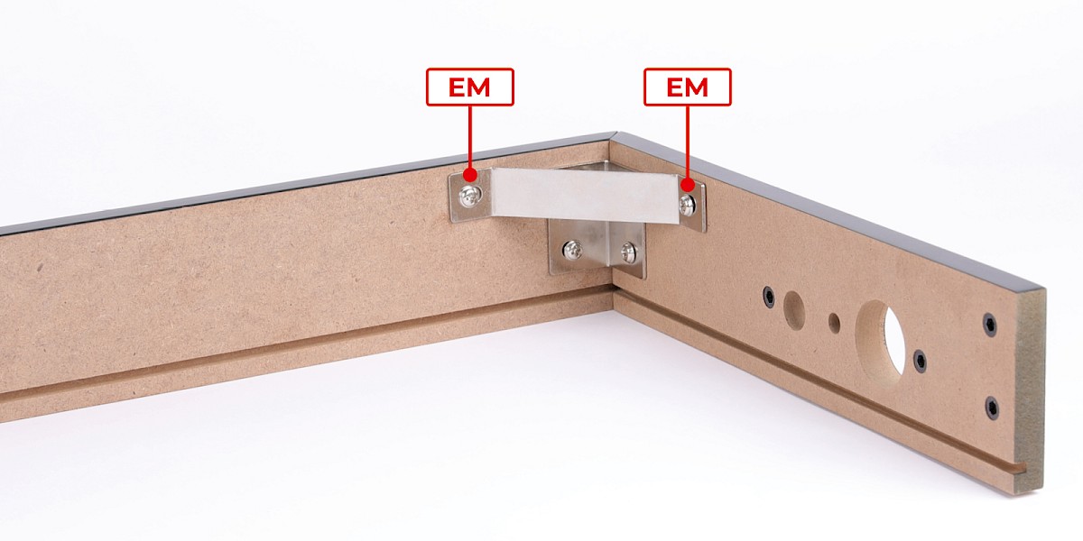
Step 3
Fit 88-E to the assembly.
Secure with 2x EM.
Step 4
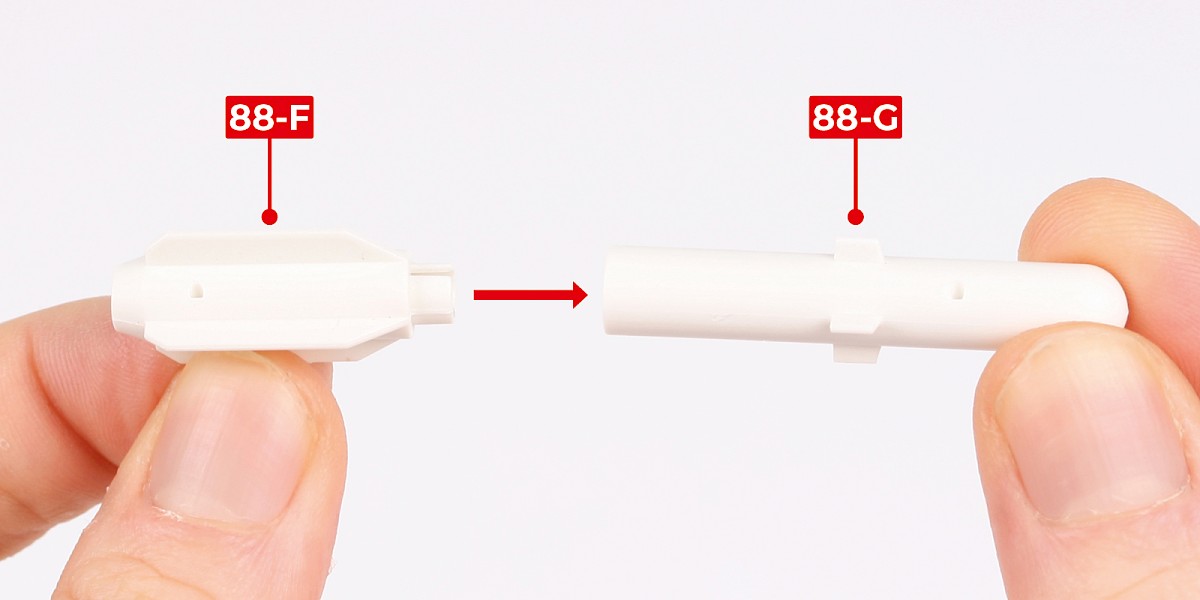
You will now build the Brimstone missiles.
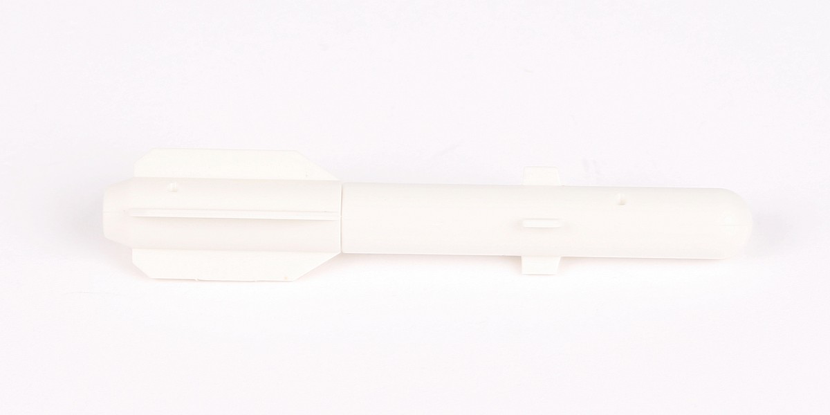
Fit 88-F to 88-G.
Step 5
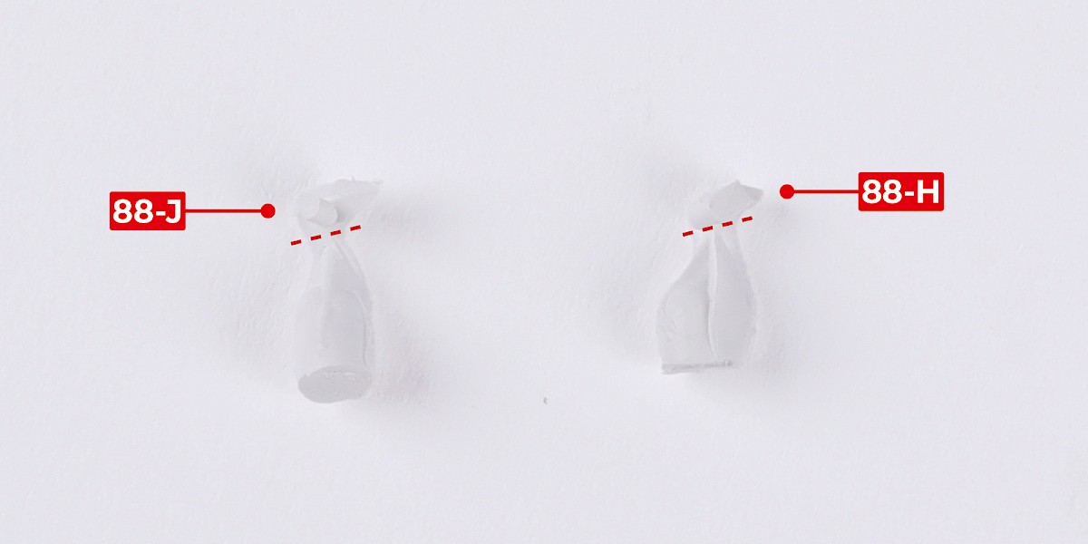
Cut parts 88-J and 88-H off the sprues.
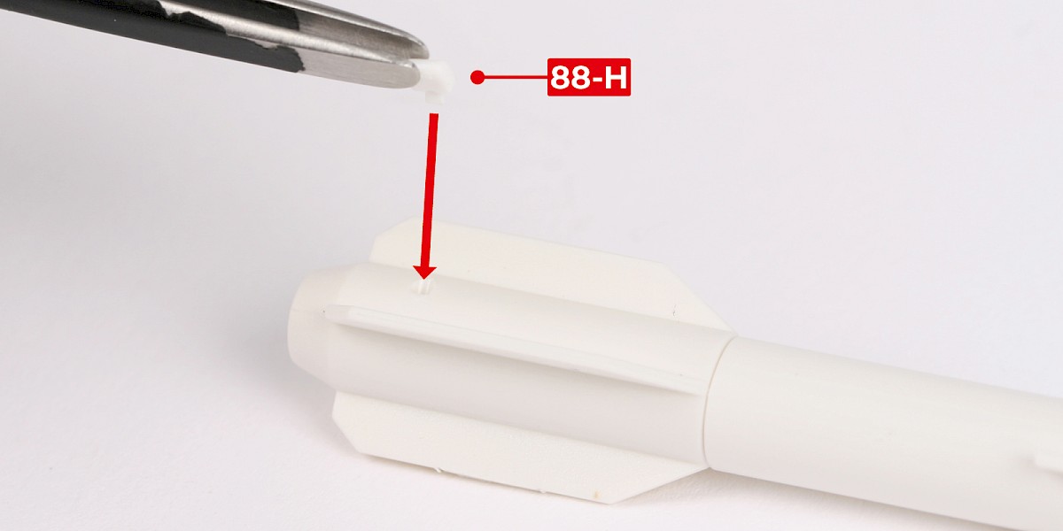
Step 6
Glue 88-H to the assembly.
Step 7
Glue 88-J to the assembly.
Step 8
Cut the decals outlined in red from 85-K.
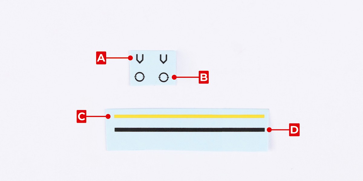
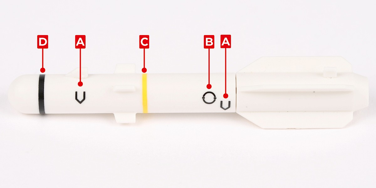
Step 9
Apply decals A, B, C and D to the missile.
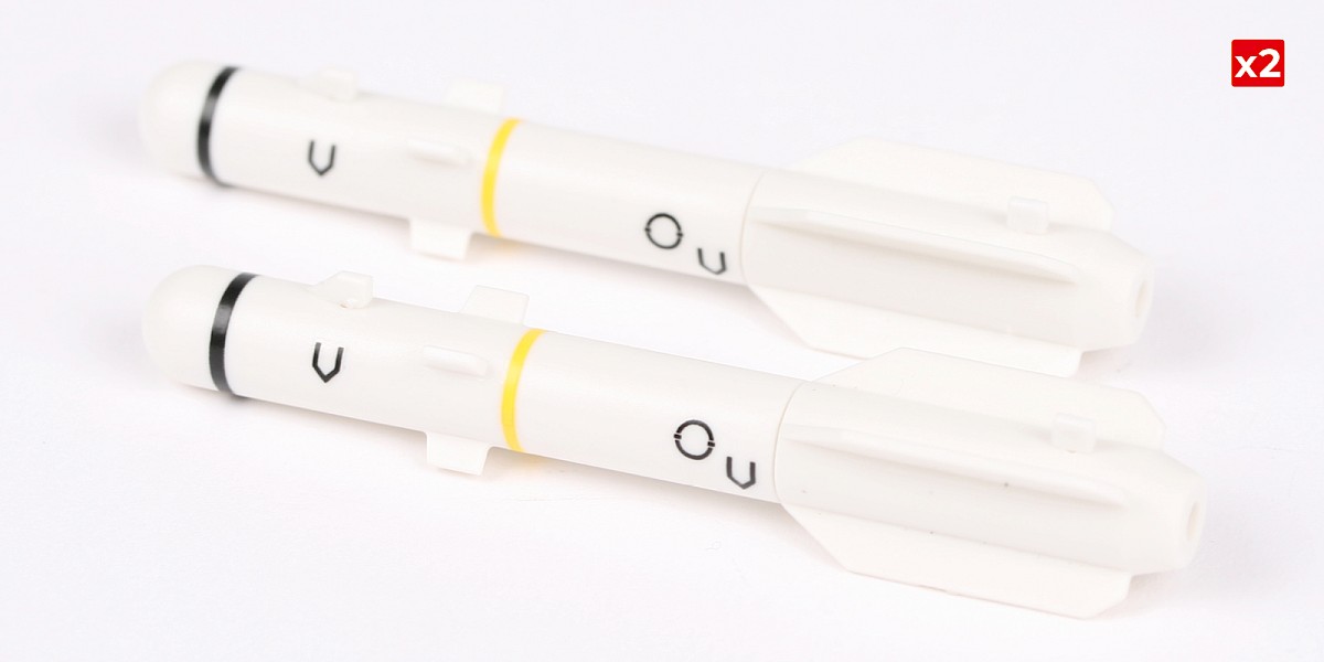
Repeat this process to assemble two missiles.
Step 10
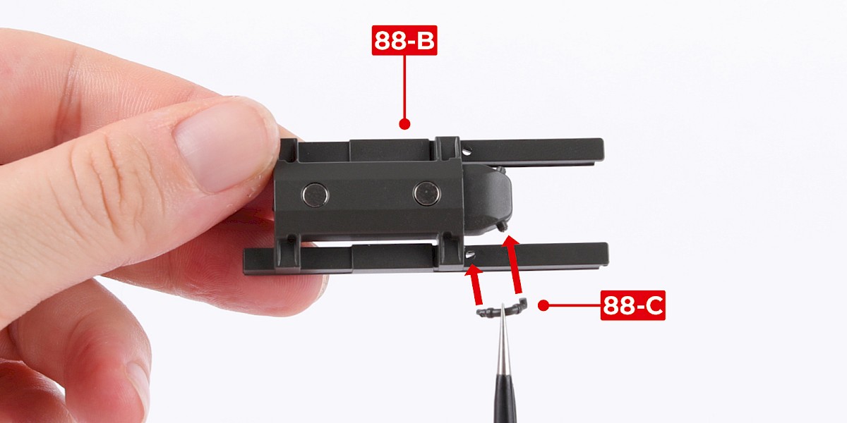
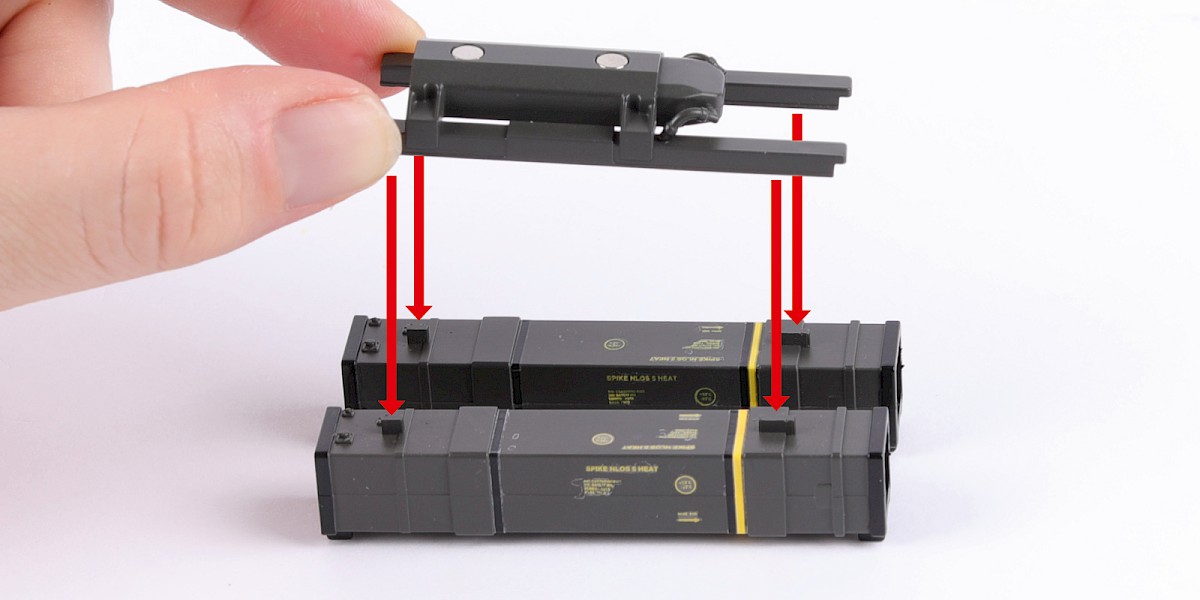
You will now assemble an M299 launcher with Spike missiles.
Fit 88-C to 88-B.
Fit 88-D to the assembly.

Step 11
Fit the assembly to two Spike missile launchers (stage 23).

Step 12
Cut the decals outlined in red from 85-K.

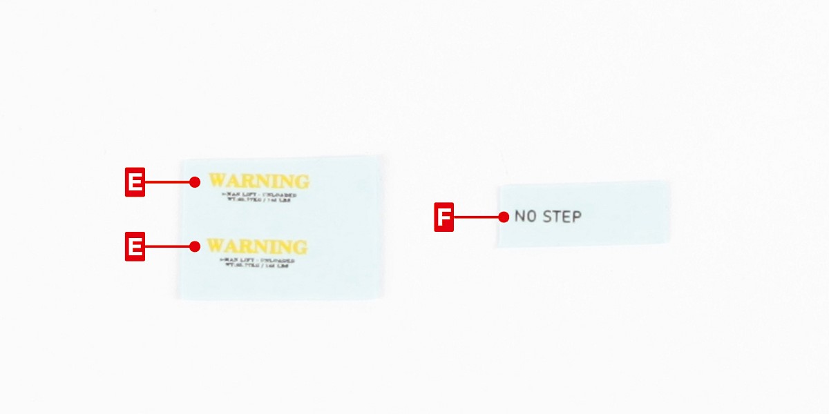
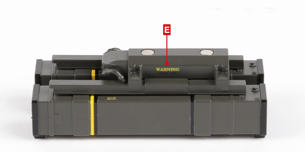
Step 13
Apply decals E to the sides of the assembly.

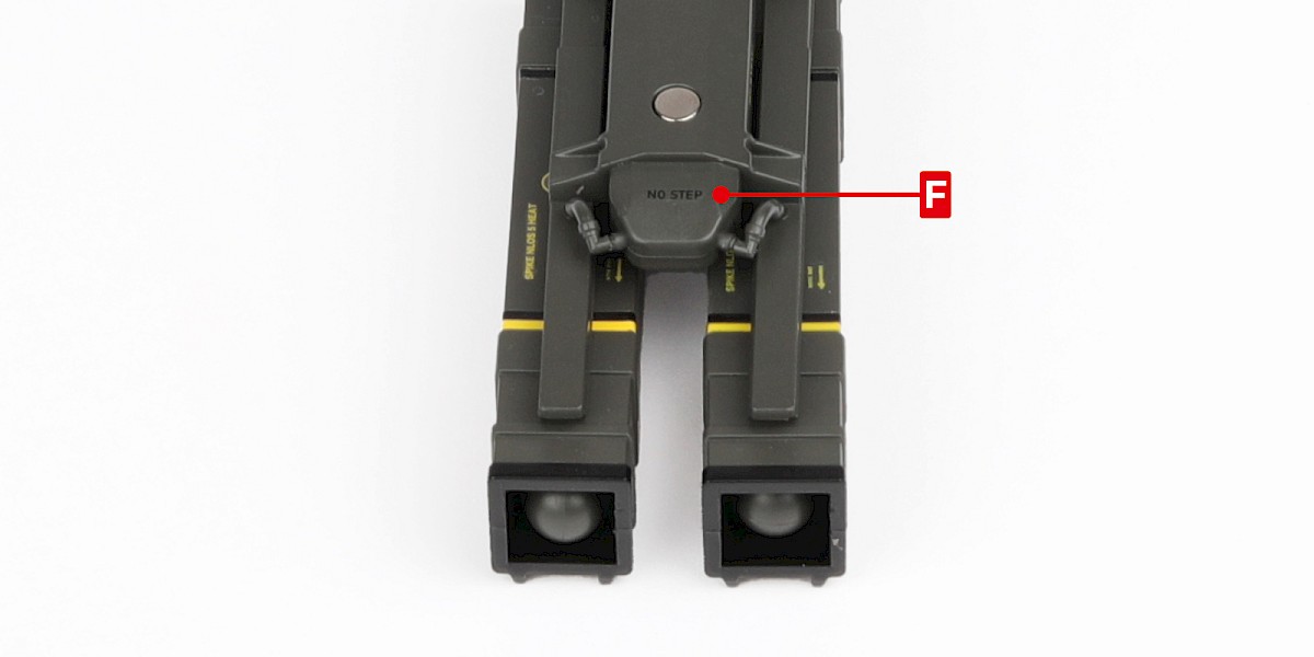
Step 14
Apply decal F to the front of the assembly.
STAGE COMPLETE
PARTS LIST
| 89-A | FP x5 |
| 89-B | HM x11 |
| 89-C | JM x3 |
| BM x5 | SP x7 |
Step 1
Fit 89-C into 89-A.
Step 2
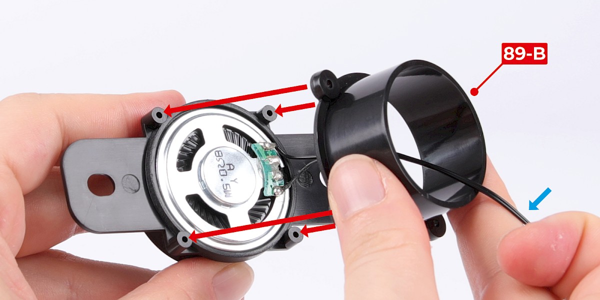
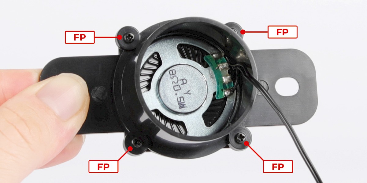
Fit 89-B to the assembly. Make sure to thread the cable through 89-B (blue arrow).
Secure with 4x FP.
Step 3
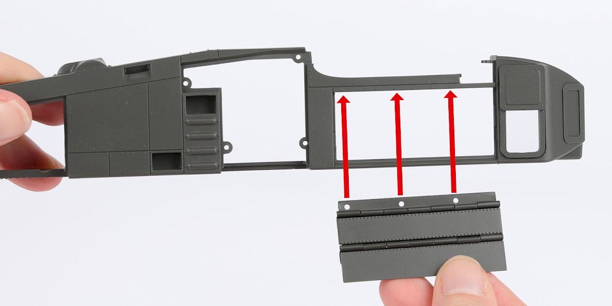
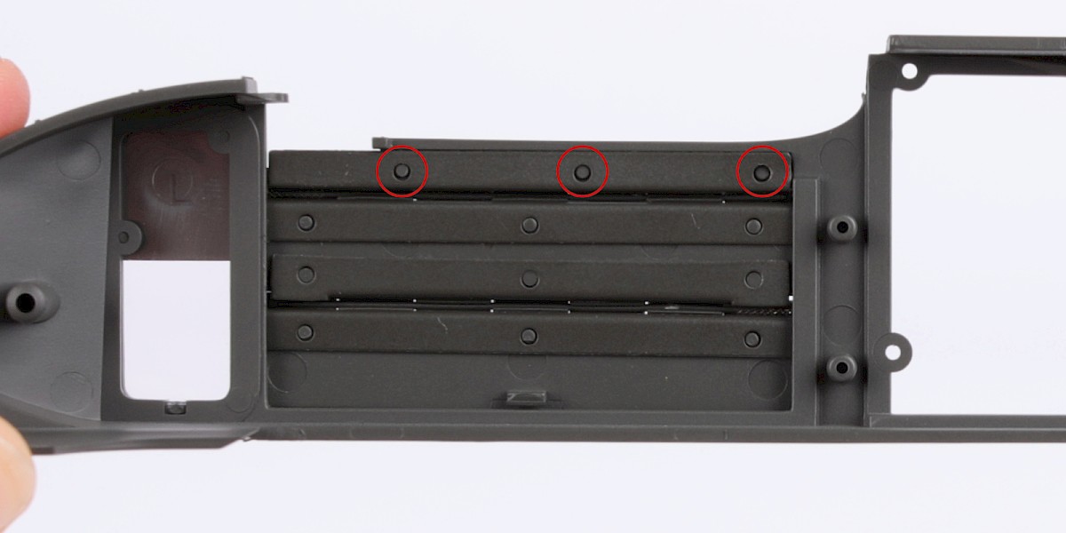
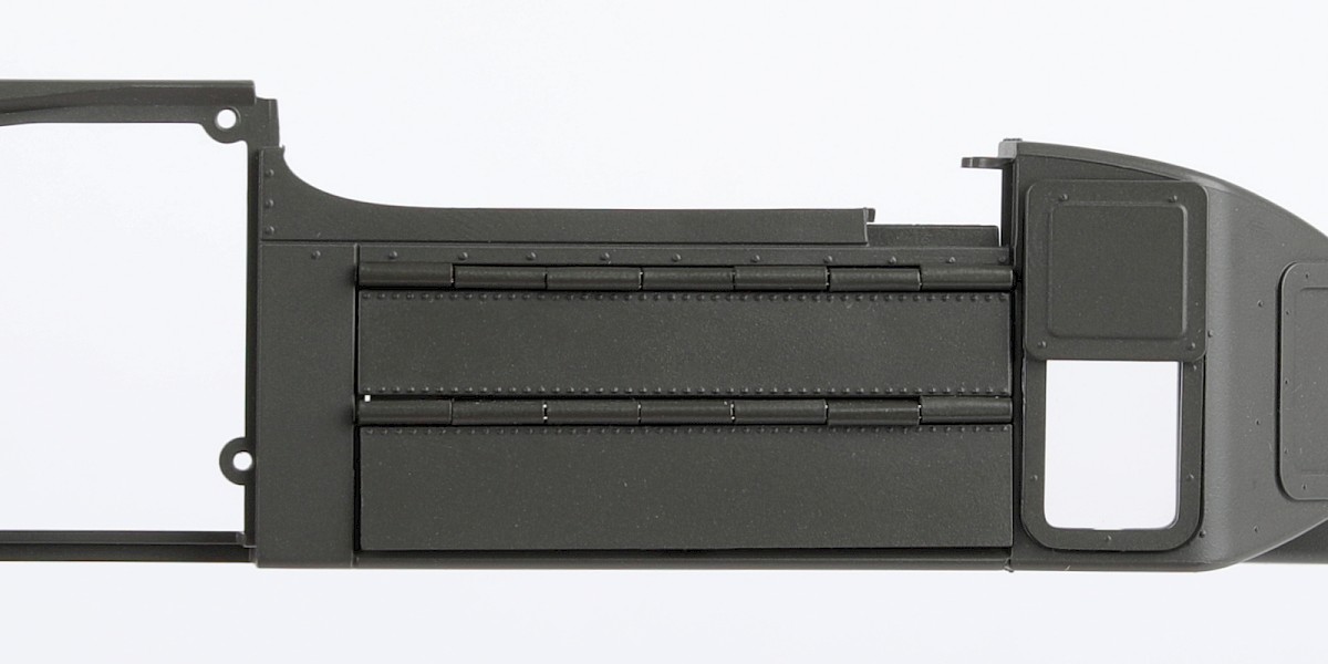
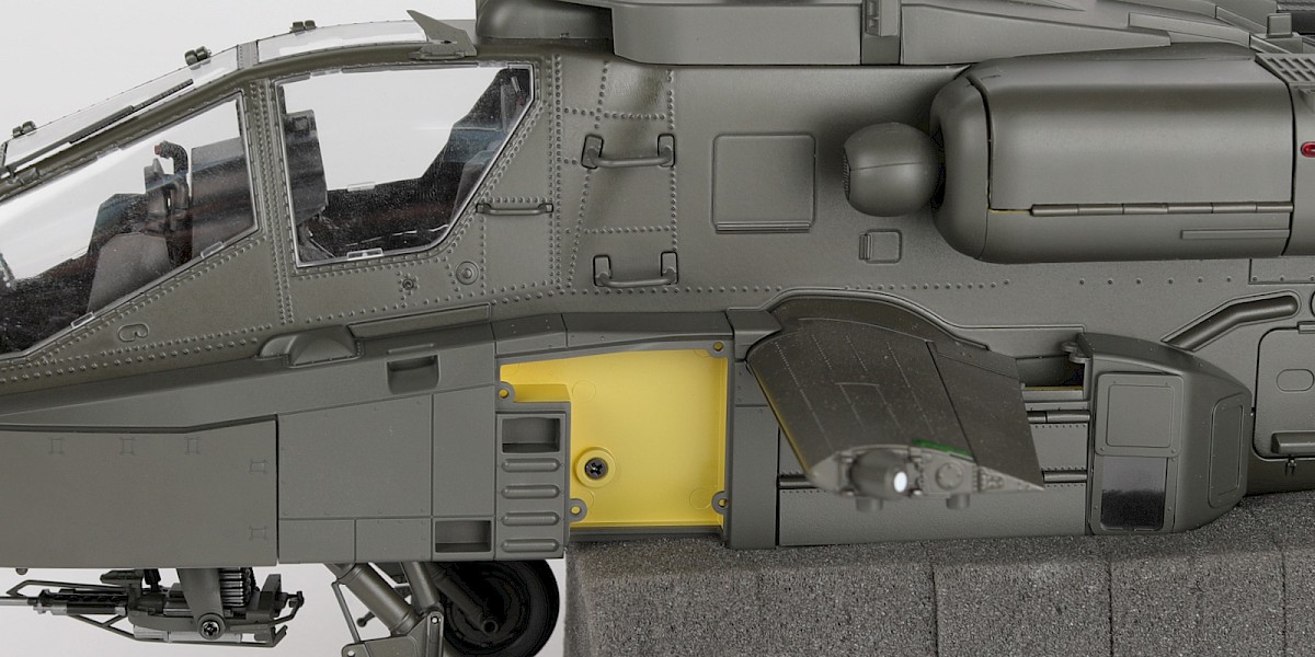
Fit the ammunition-bay door (stage 69) to the left avionics bay (stage 68).
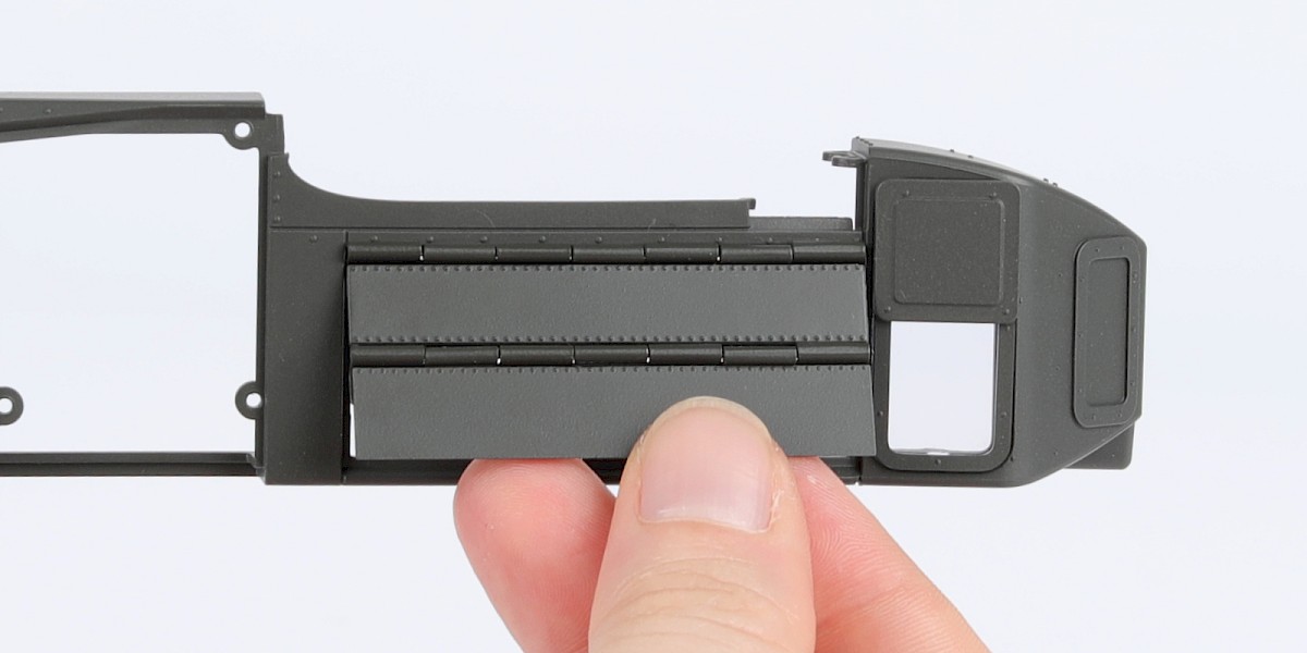
Step 4
Glue the ammunition-bay door at the points indicated by the red circles.
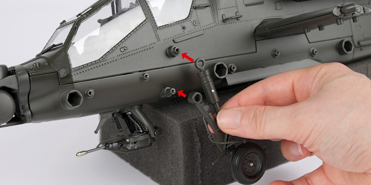
Step 5
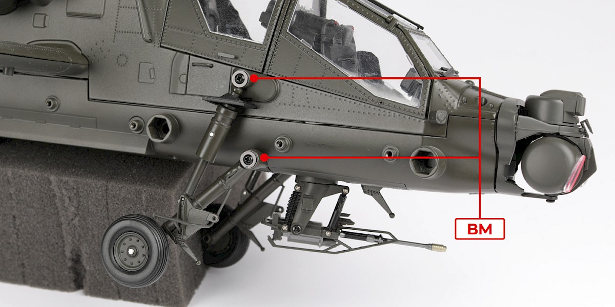
You will now fit the landing gear.
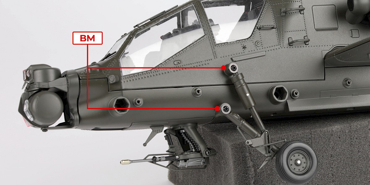
Fit the left landing gear (stage 44) to the fuselage (stage 78).
Secure with 2x BM.
Step 6
Fit the right landing gear (stage 47) to the fuselage.
Secure with 2x BM.
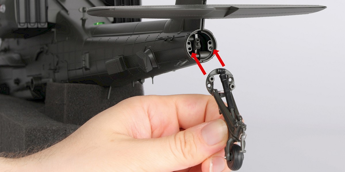
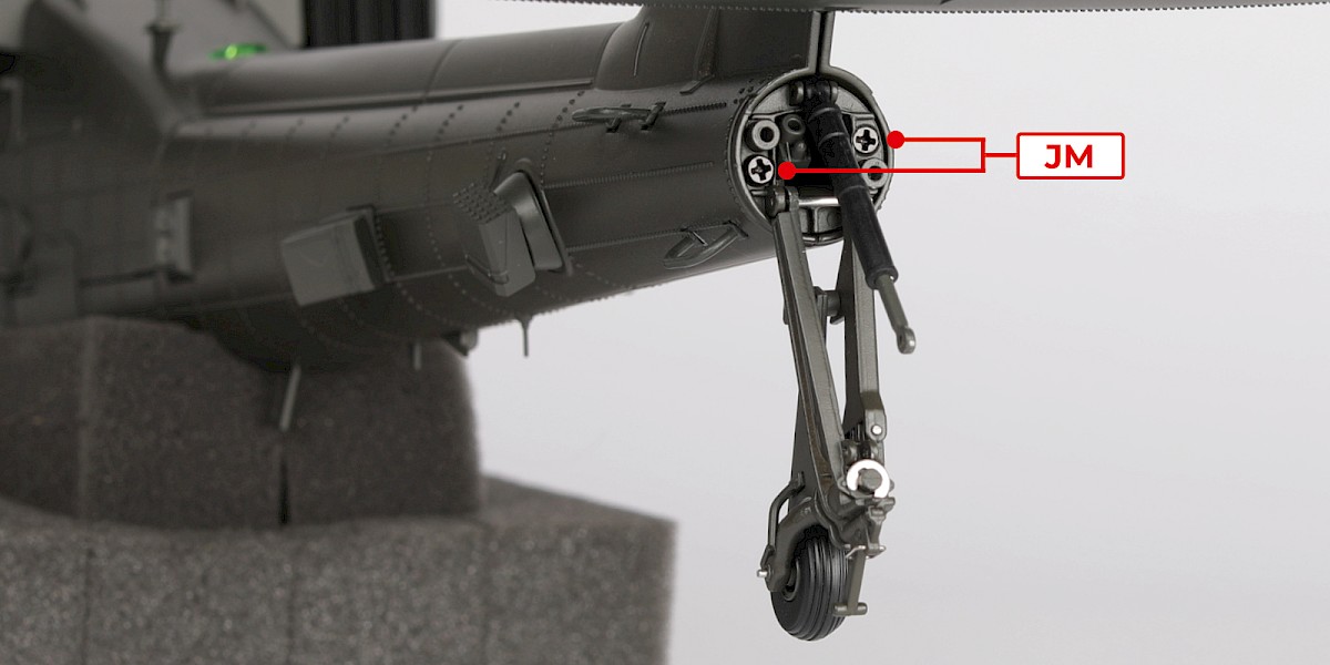
Step 7
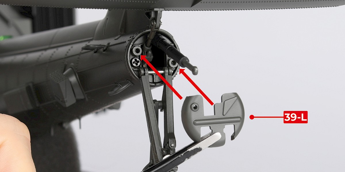
Fit the tail landing gear (stage 39) to the tail.
Secure with 2x JM.
Note: If the cover has already been fitted to the tail landing gear, remove the pin (39-U) holding the piston and then pull off the cover (39-L).
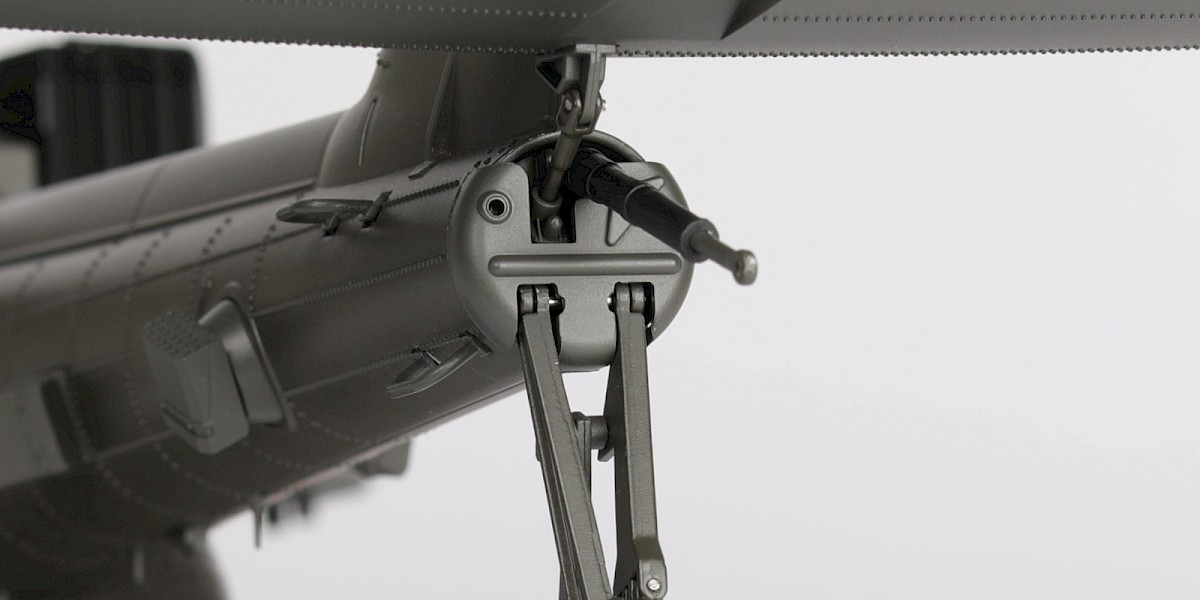
Step 8
Fit the stabilator strut (stage 39) to the assembly as shown.
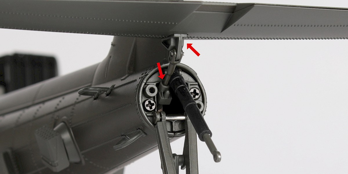
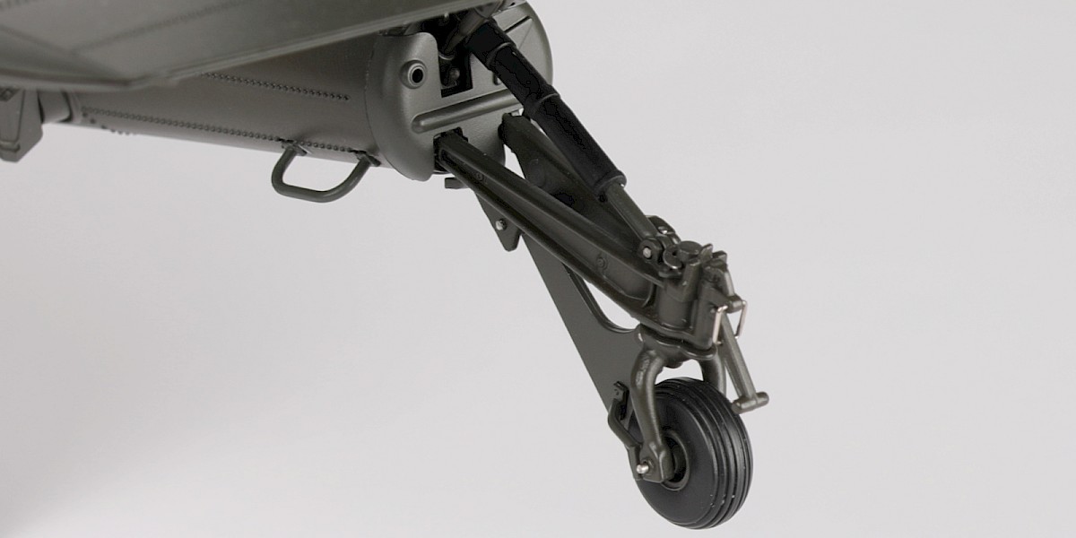
Step 9
Fit 39-L to the assembly.
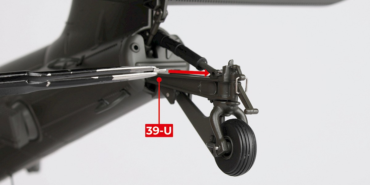
Step 10
Fit the control rod in place and secure with 39-U.
Step 11
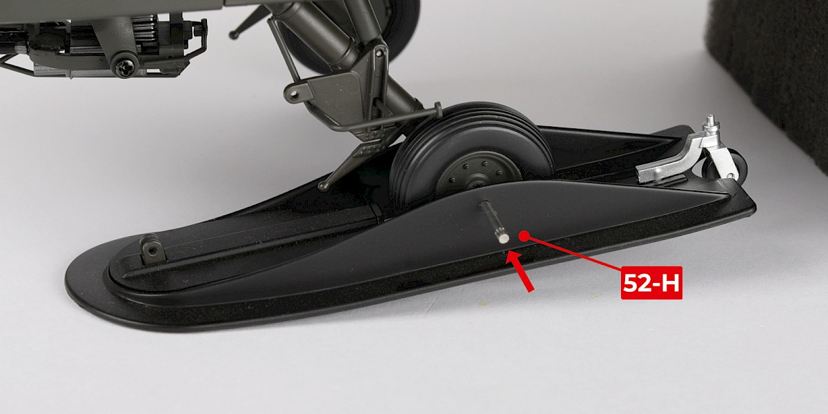
Fitting the skis.
Steps 11 – 18 are optional . If you choose not to fit the skis to your model, you can skip to step 19. You will not be able to remove the skis once they are fitted.
Fit the left ski (stage 52) as shown. Secure with 52-H.
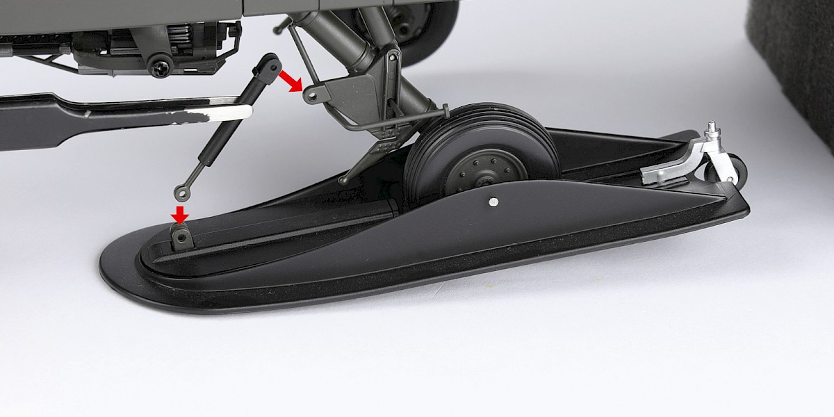
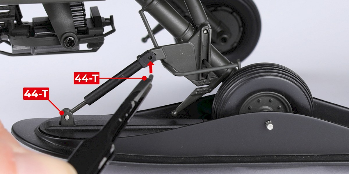
Step 12
Fit the piston (stage 44).
Secure with two 44-T.
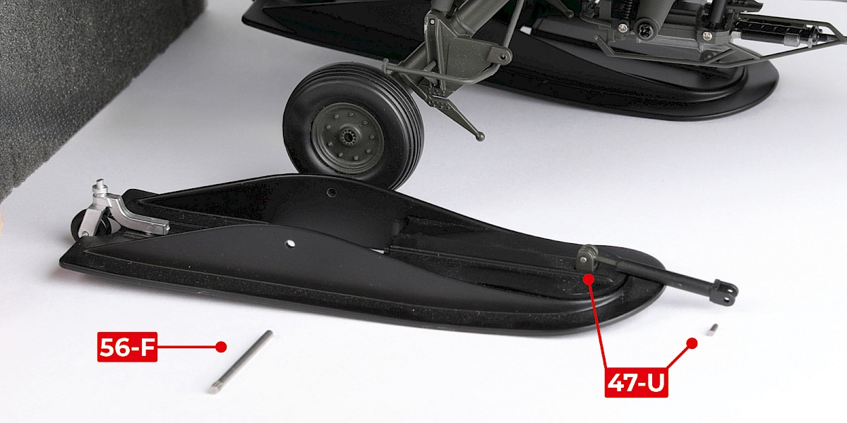
Step 13
Repeat this process to fit the right ski (stage 56) and piston (stage 47).
Secure with 56-F and two 47-U.
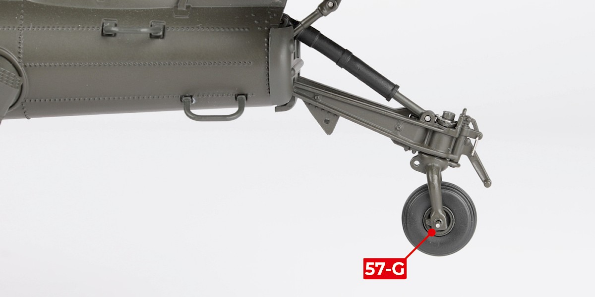
Step 14
Fit the tail wheel (stage 57) in place using 57-G.
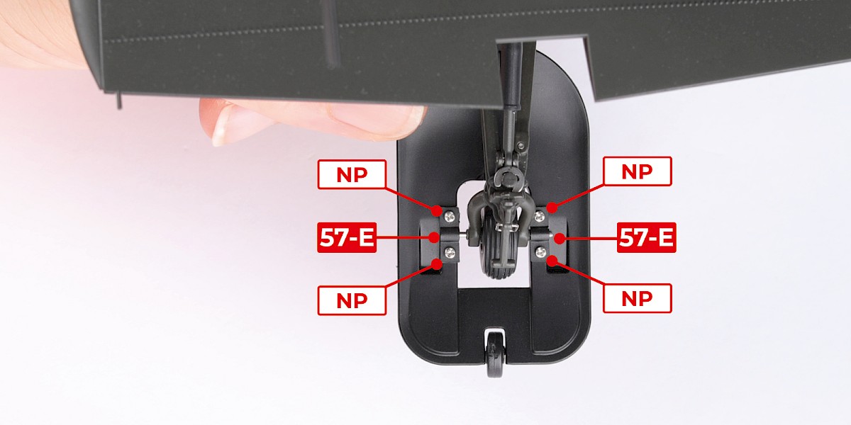
Step 15
Fit the tail ski (stage 57). Secure in place with two 57-E and 4x NP (supplied with stage 57) as shown.
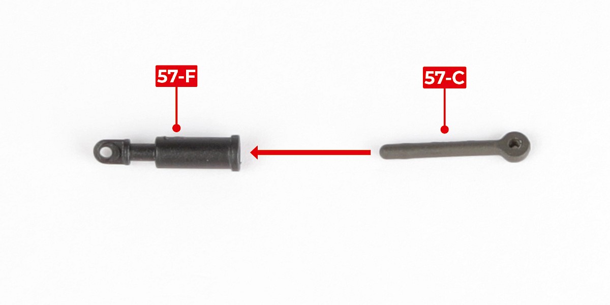
Step 16
Fit 57-C into 57-F.
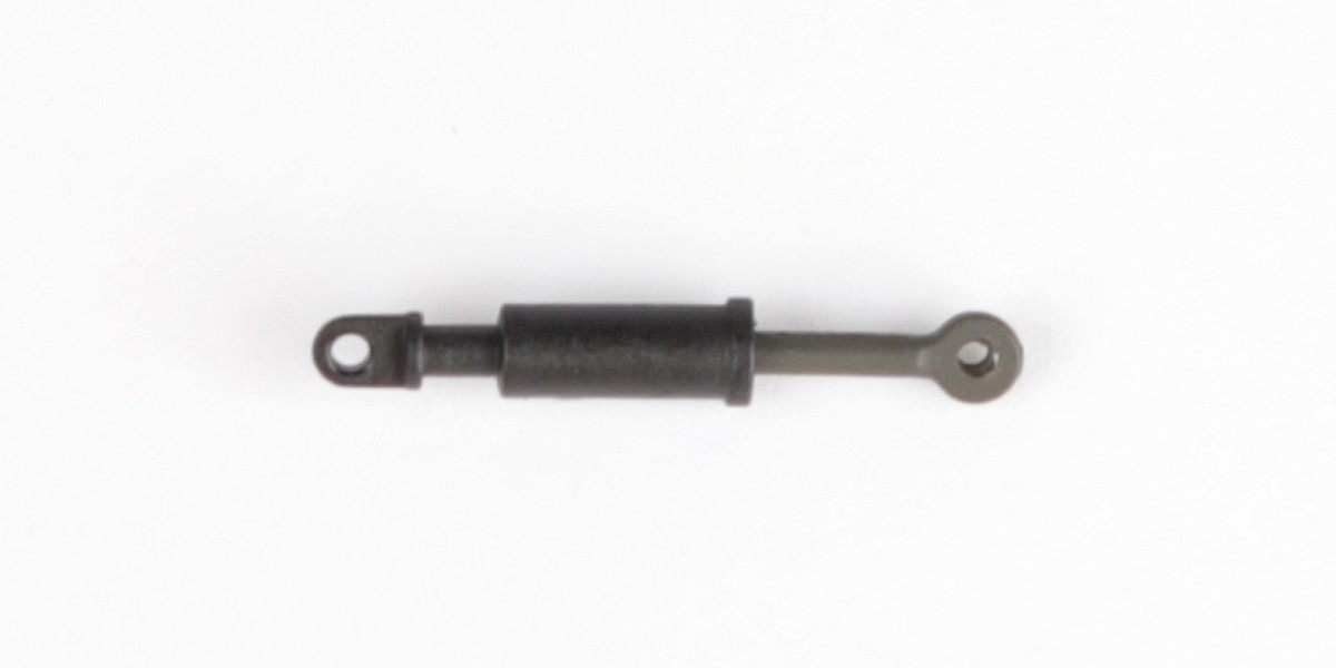
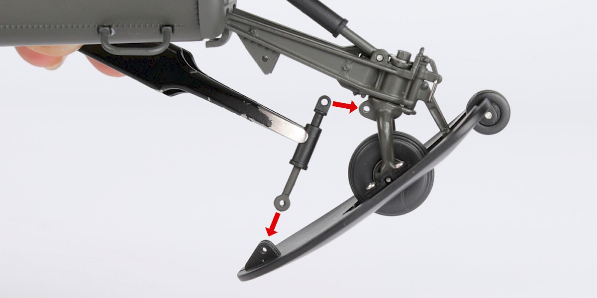
Step 17
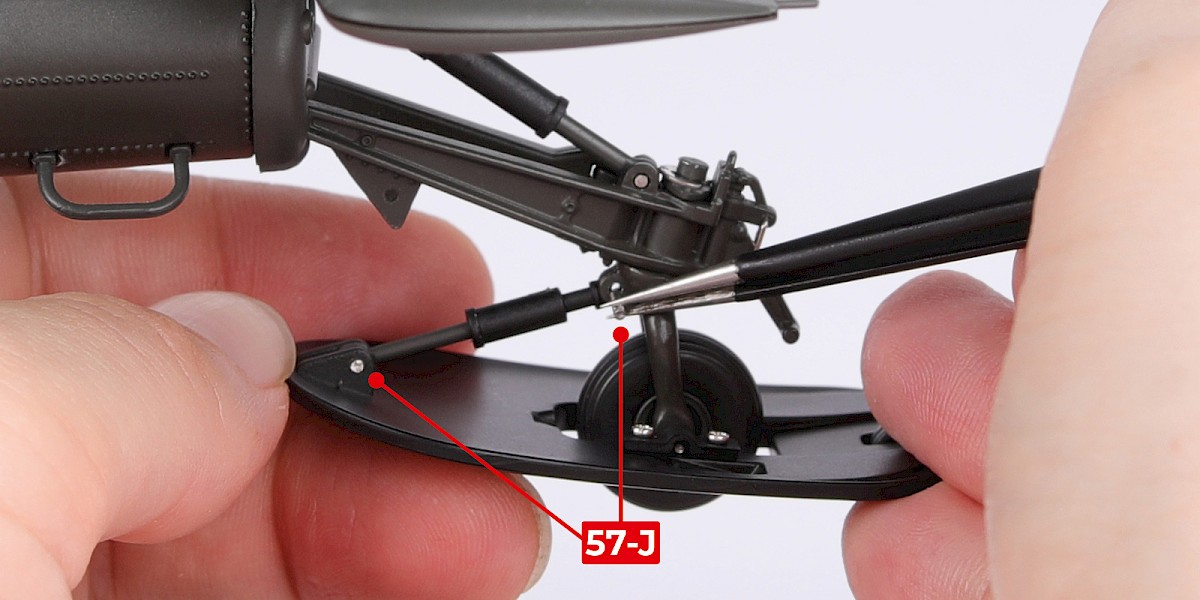
Fit the piston to the assembly.
Secure with two 57-J.
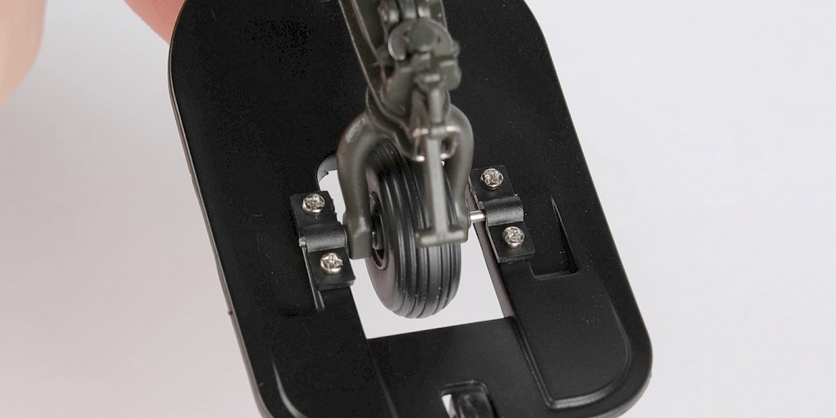
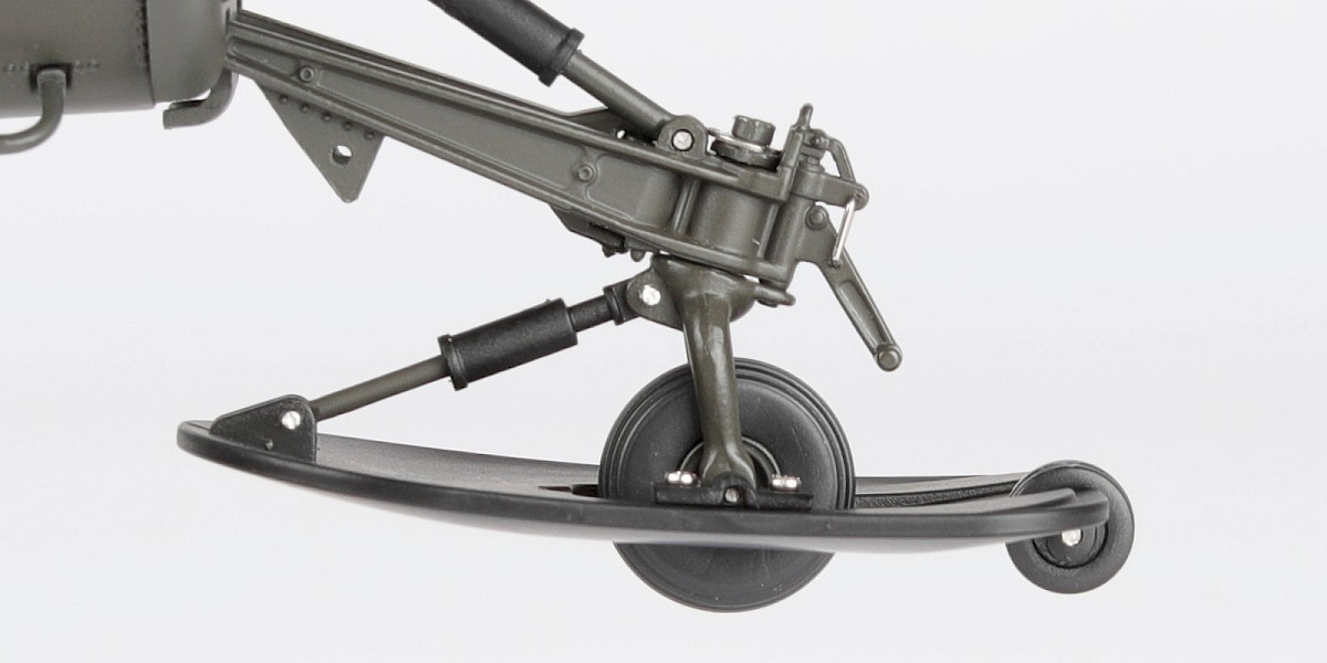
Step 18
The tail ski should look like this.
Step 19
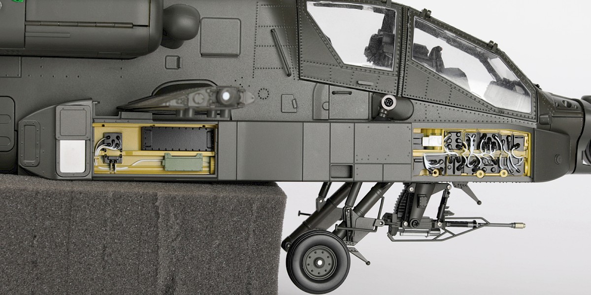
You will now fit the avionics bays.
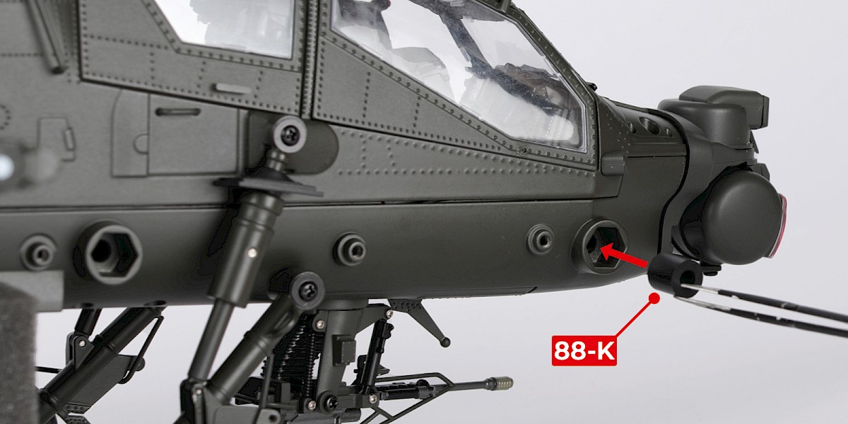
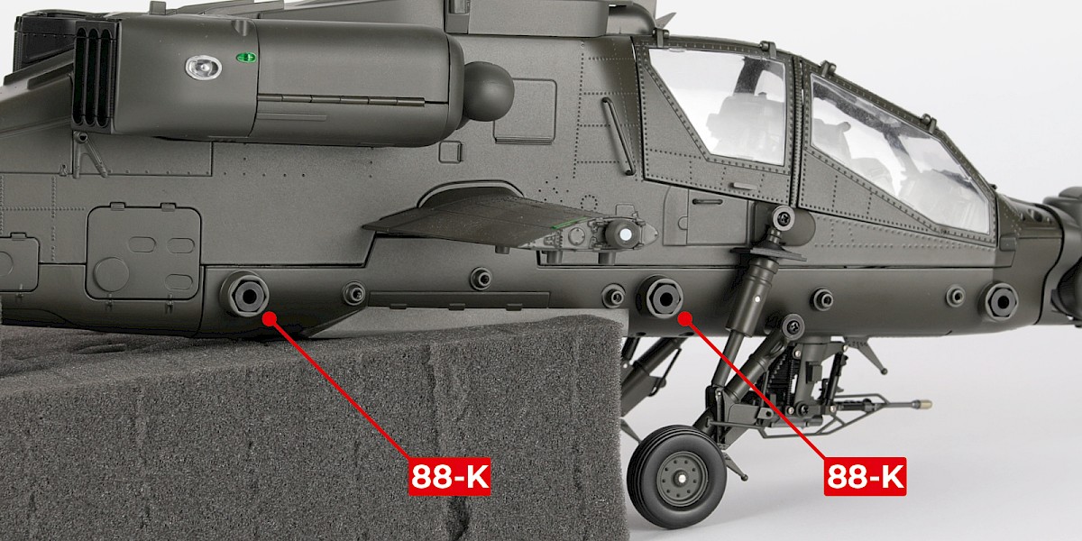
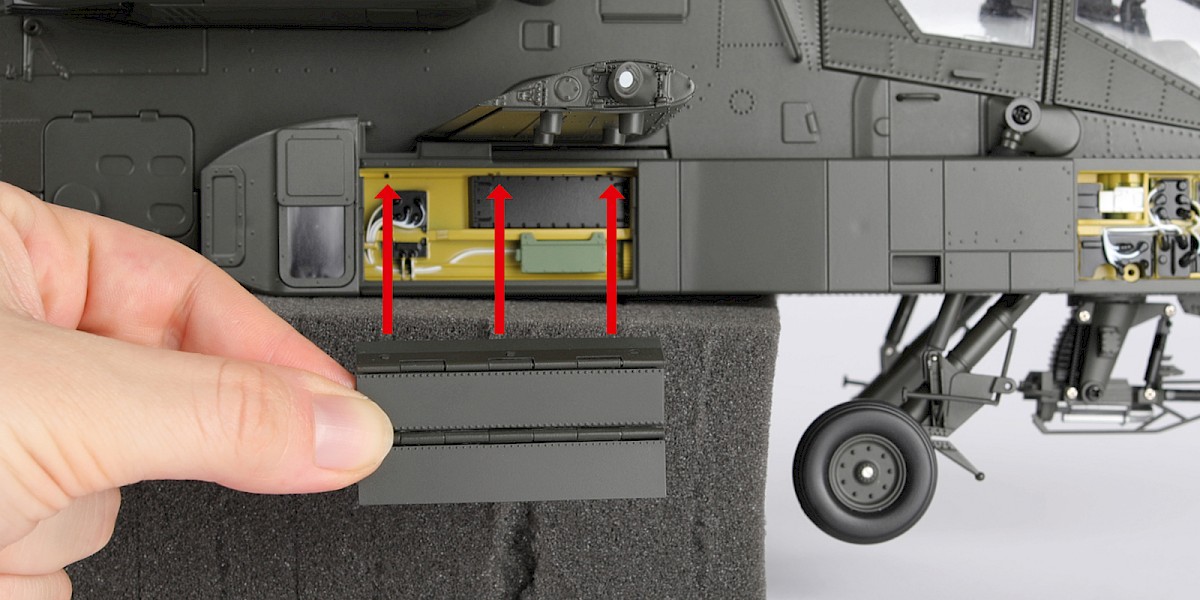
Press 88-K into the right-side of the assembly.
Press two more 88-K into the assembly as shown.
Step 20
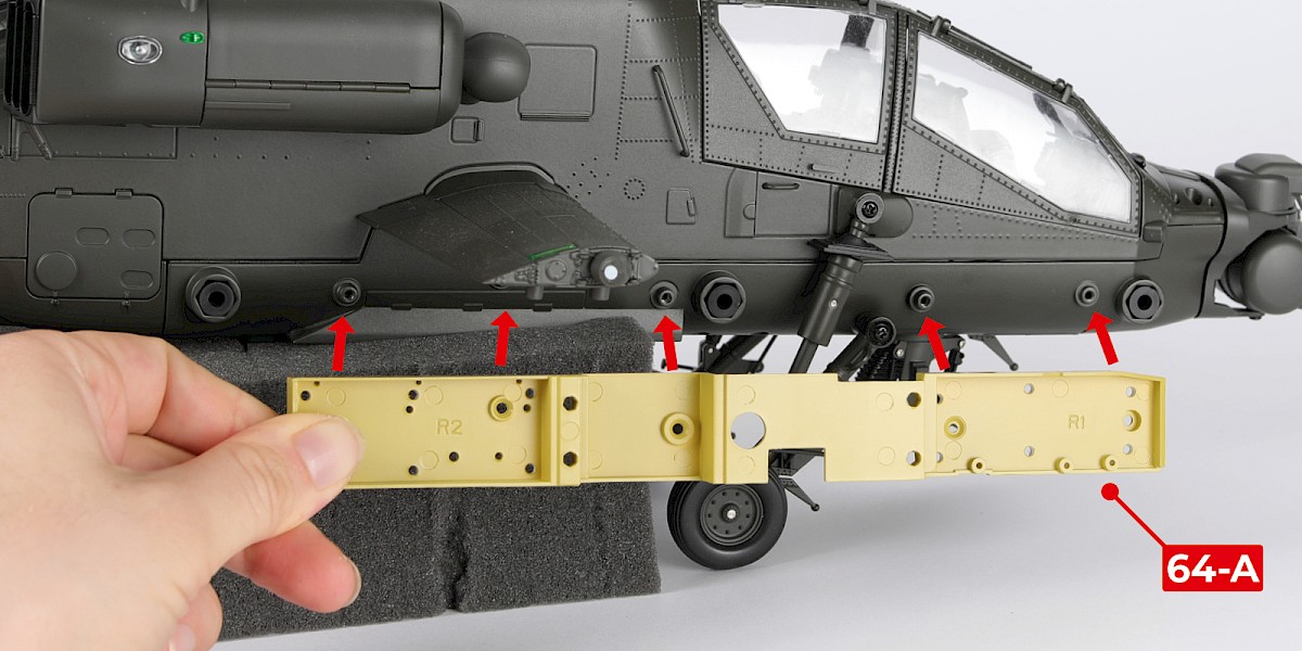
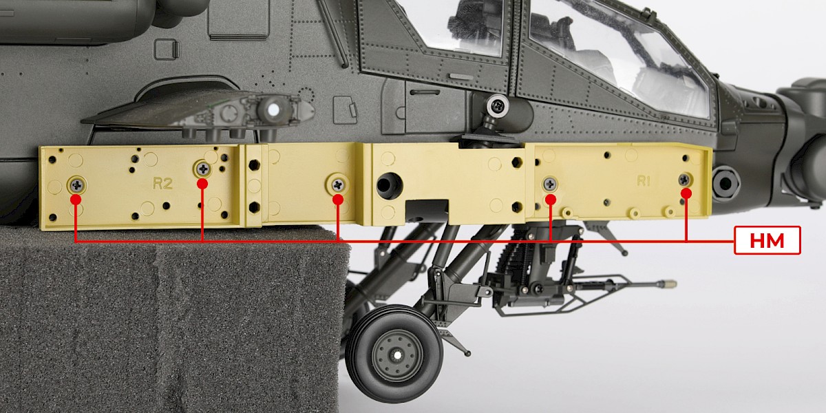
Fit 64-A to the assembly.
Secure with 5x HM.
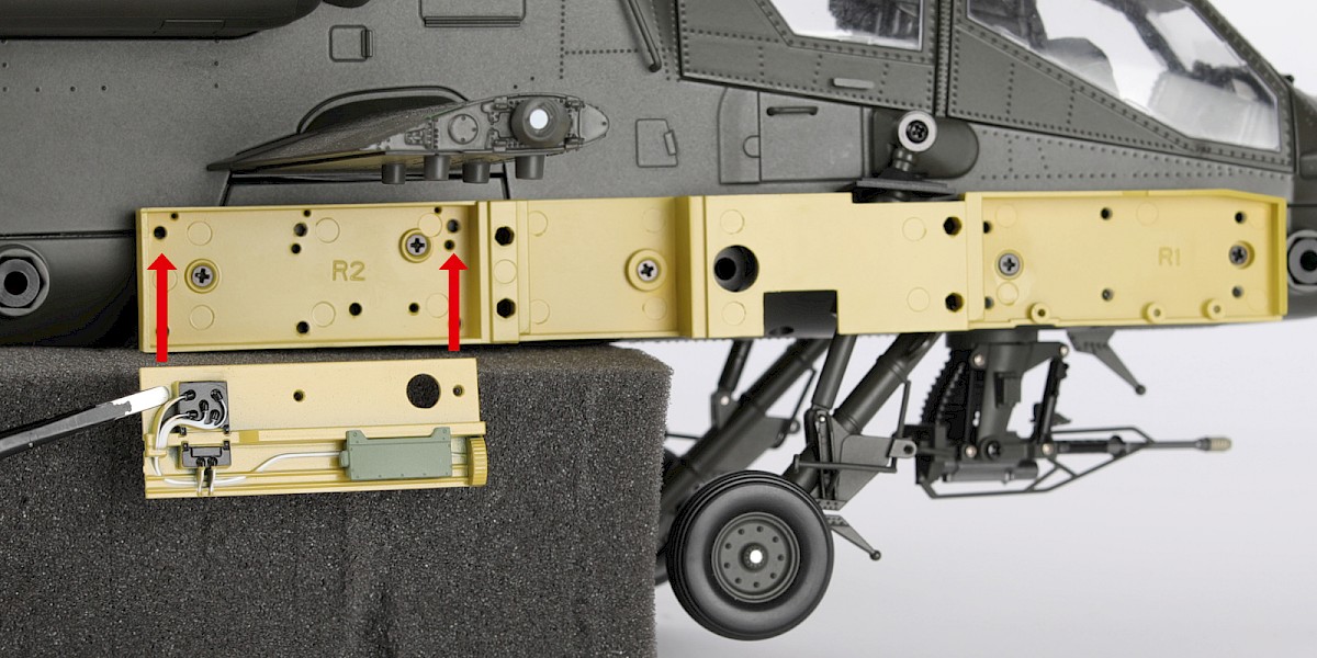
Step 21
Fit the rear EFAB panel (stage 64) to the assembly. You may need to file off excess paint from the pins.
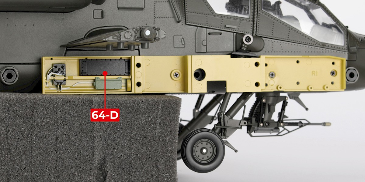
Fit 64-D to the assembly.
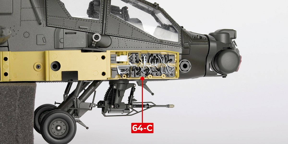
Step 22
Fit 64-C to the assembly. You may need to file off excess paint from the pins.
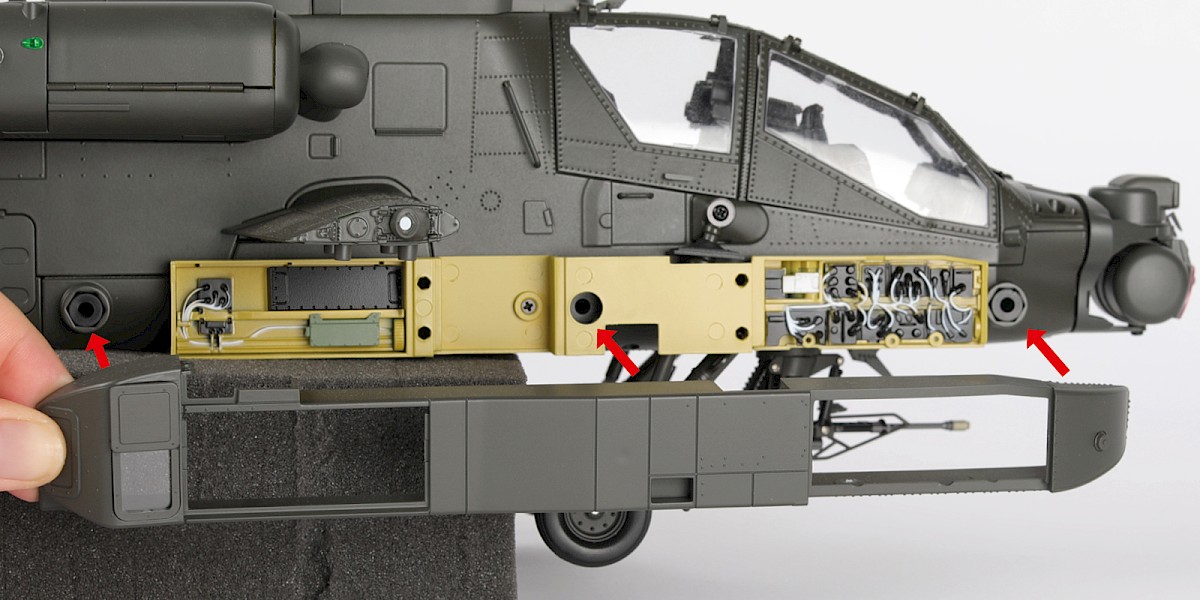
Step 23
Fit the right avionics bay (stage 65) to the assembly.
Step 24
Fit the right ammunition bay door (stage 65) to the assembly.
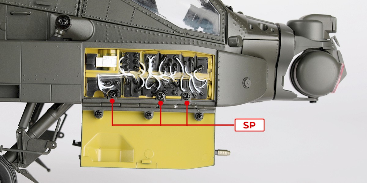
Step 25
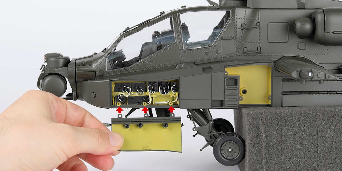
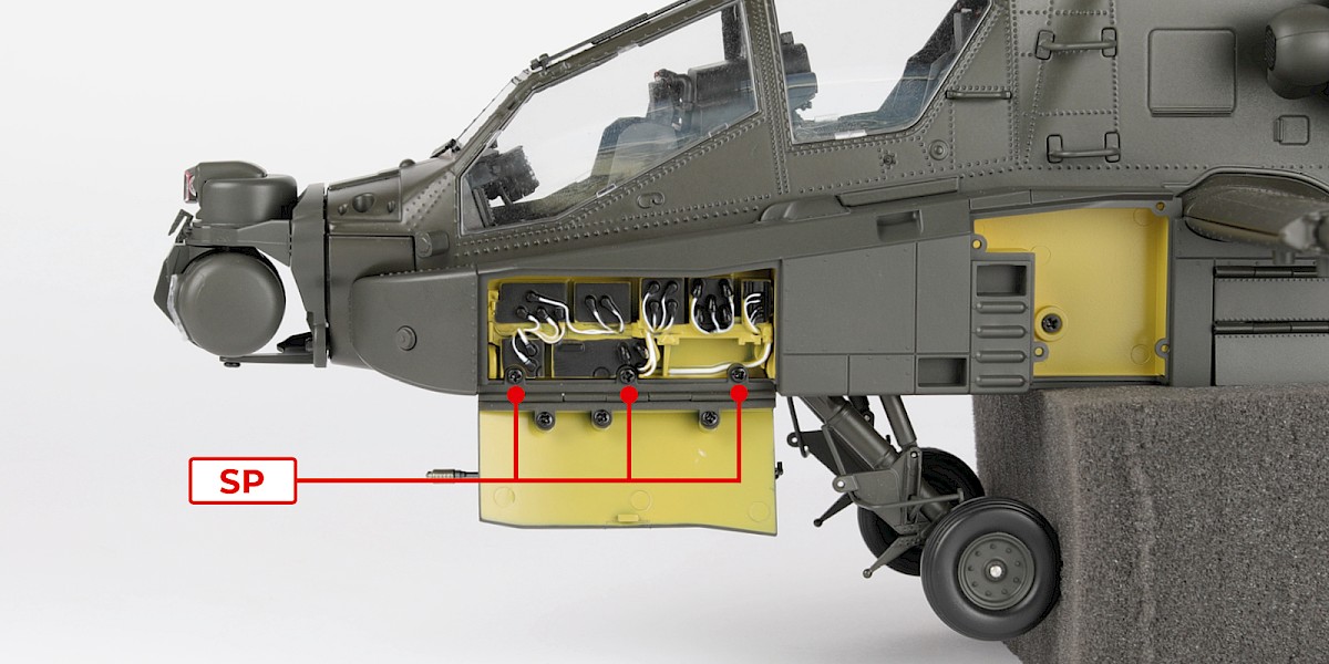
Fit the right avionics bay door (stage 63) to the assembly.
Secure with 3x SP.
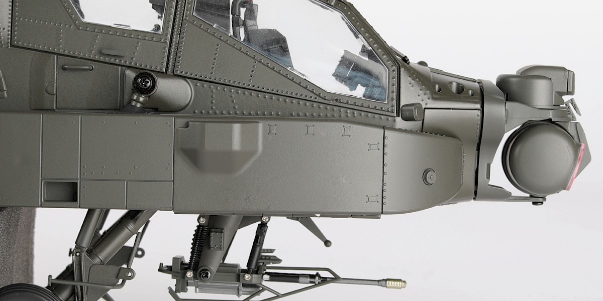
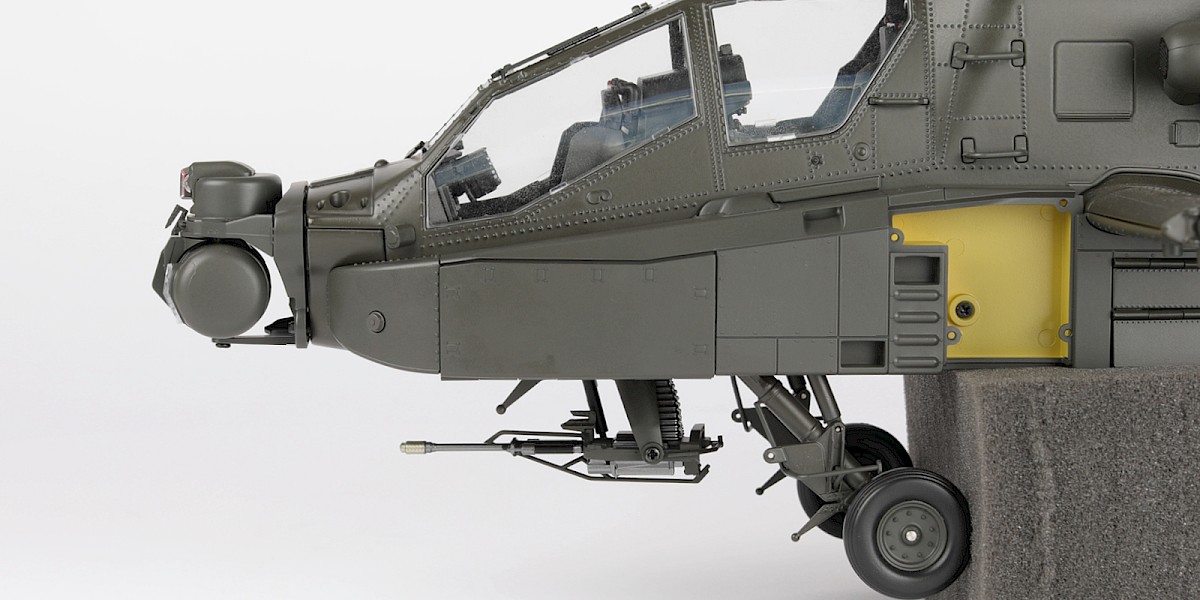
Step 26
Check the door closes. You may need to adjust the screws.
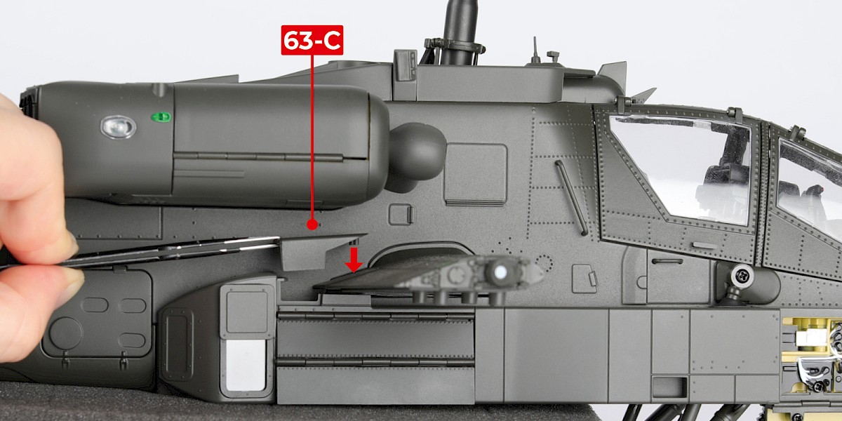
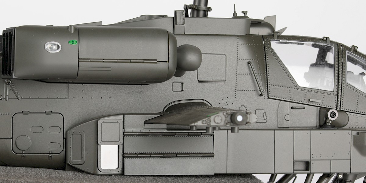
Step 27
Fit 63-C to the assembly.
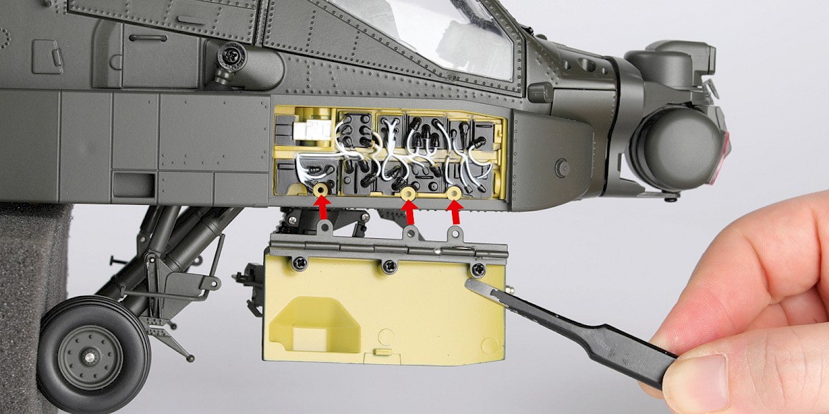
Step 28
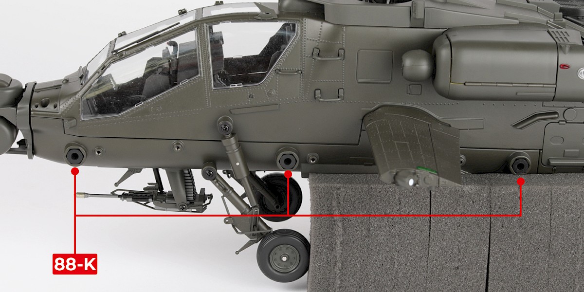
Press three 88-K into the left-side of the assembly.
Step 29
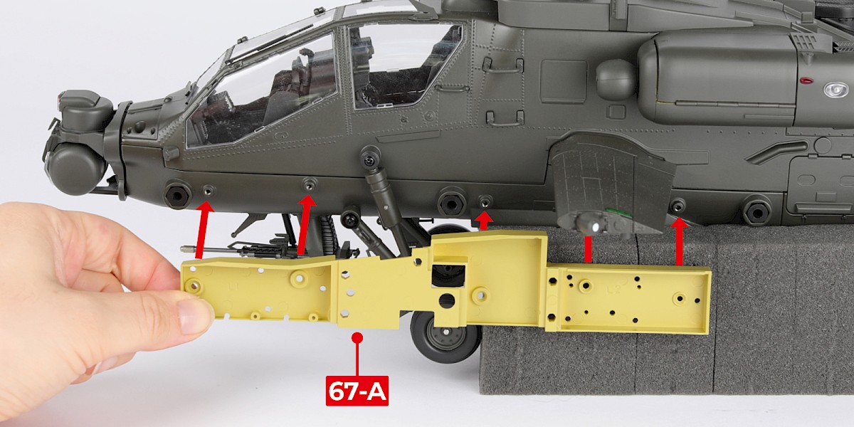
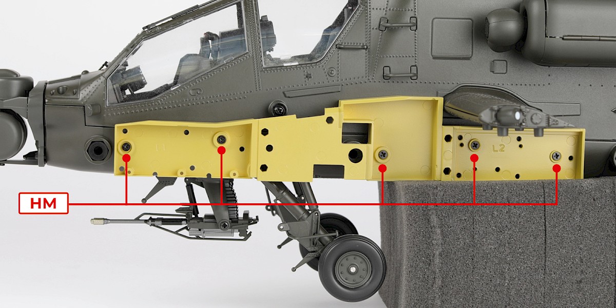
Fit 67-A to the assembly.
Secure with 5x HM.
Step 30
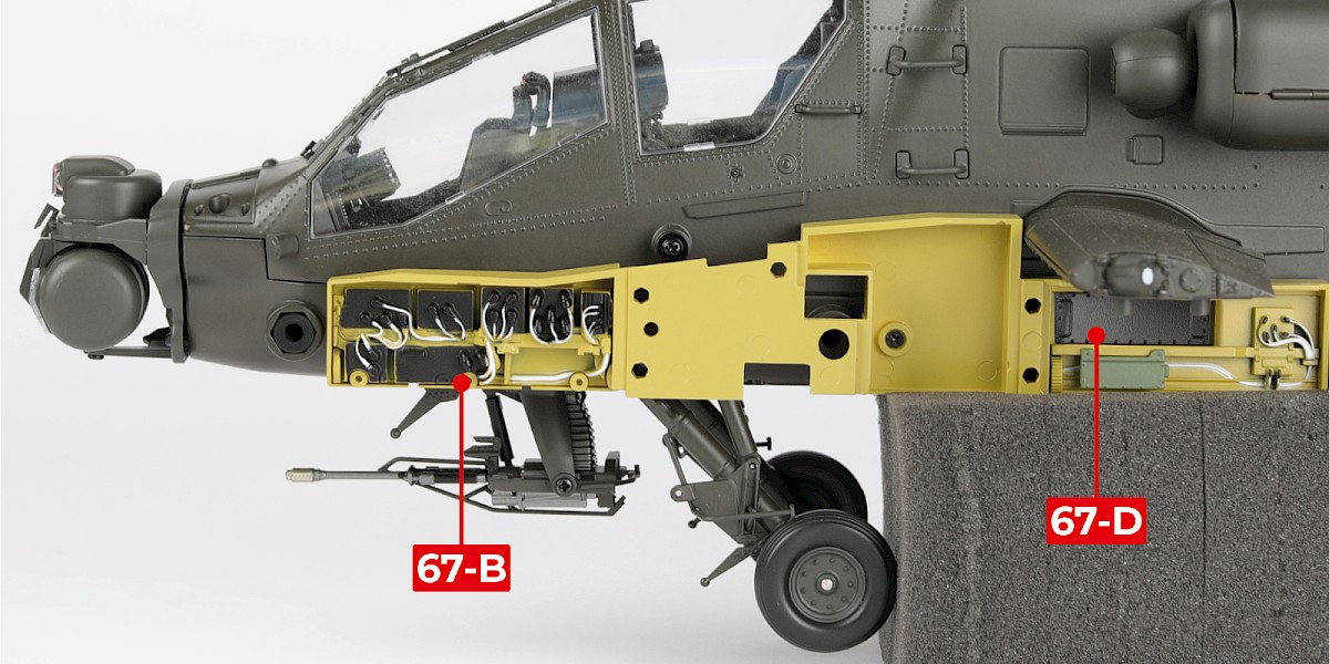
Fit the rear EFAB panel (stage 67) to the assembly. You may need to file off excess paint from the pins.
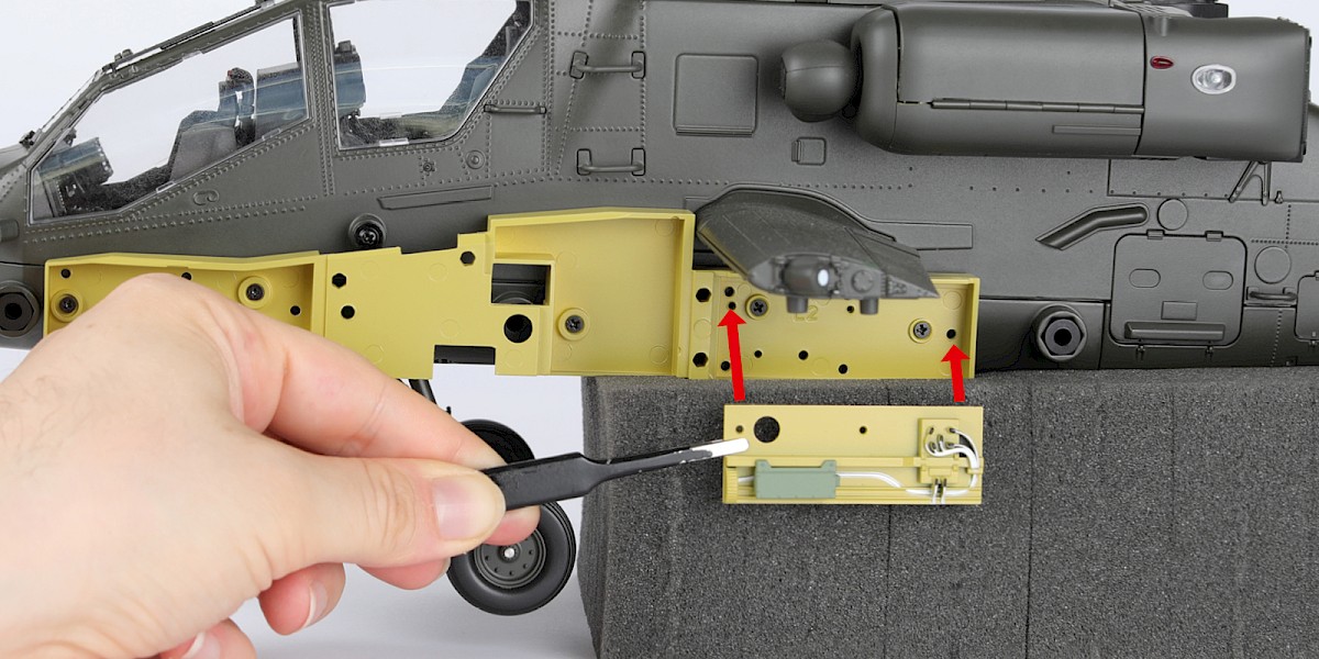
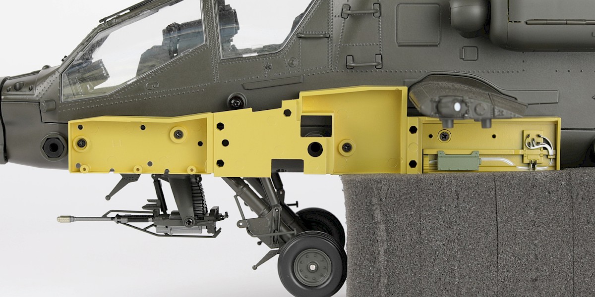
Step 31
Fit 67-B and 67-D to the assembly. You may need to file off excess paint from the pins.
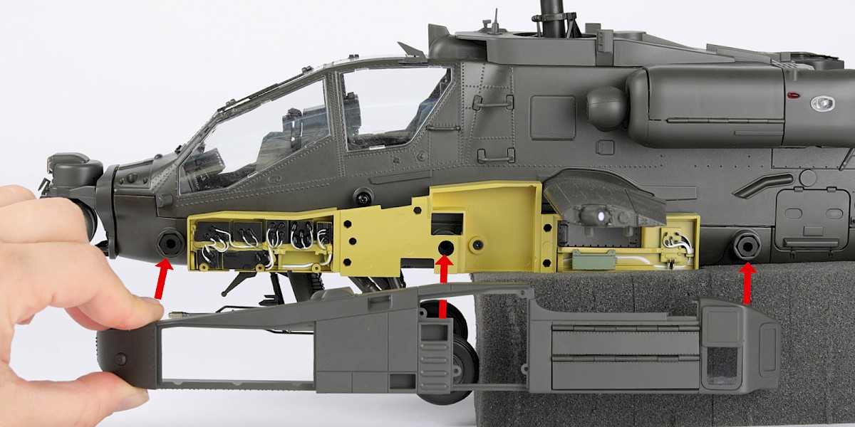
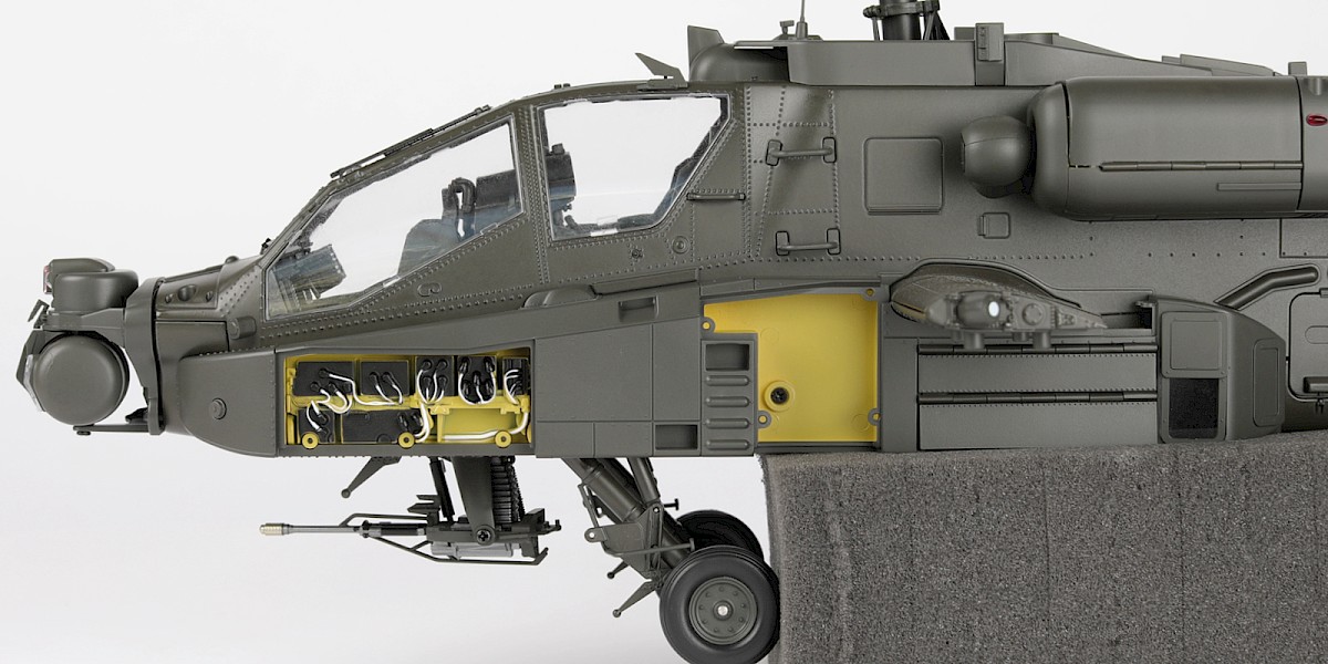
Step 32
Fit the left avionics bay (step 4) to the assembly.
Step 33
Fit the left avionics bay door (stage 69) to the assembly.
Secure with 3x SP.
Step 34
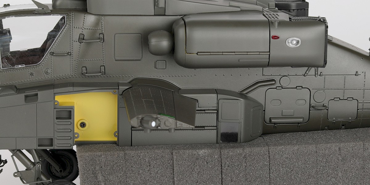
Check the door closes. You may need to adjust the screws.
Step 35
Fit 68-H to the assembly.
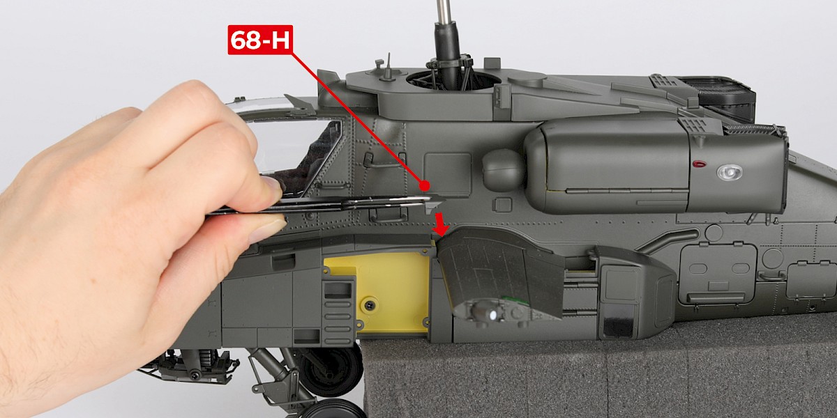
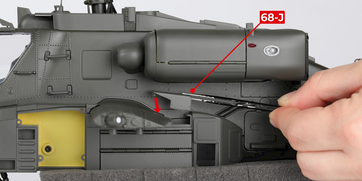
Step 36
Fit 68-J to the assembly.
STAGE COMPLETE
PARTS LIST
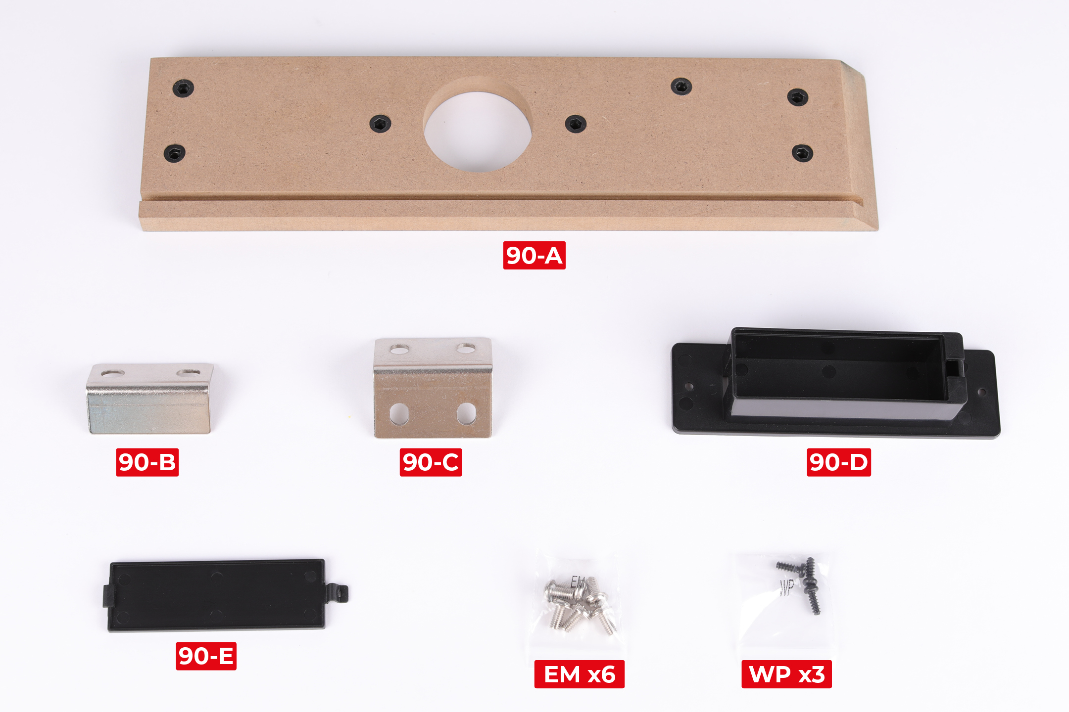
| 90-A | 90-E |
| 90-B | EM x6 |
| 90-C | WP x3 |
| 90-D |
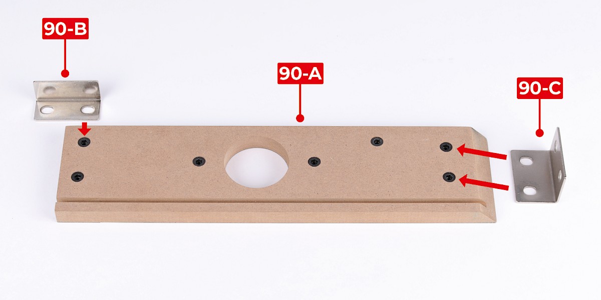
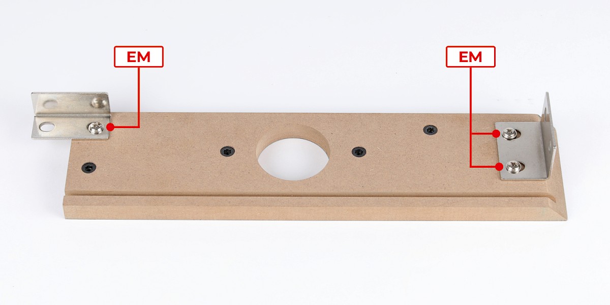
Step 1
Fit 90-B and 90-C to 90-A.
Secure with 3x EM.
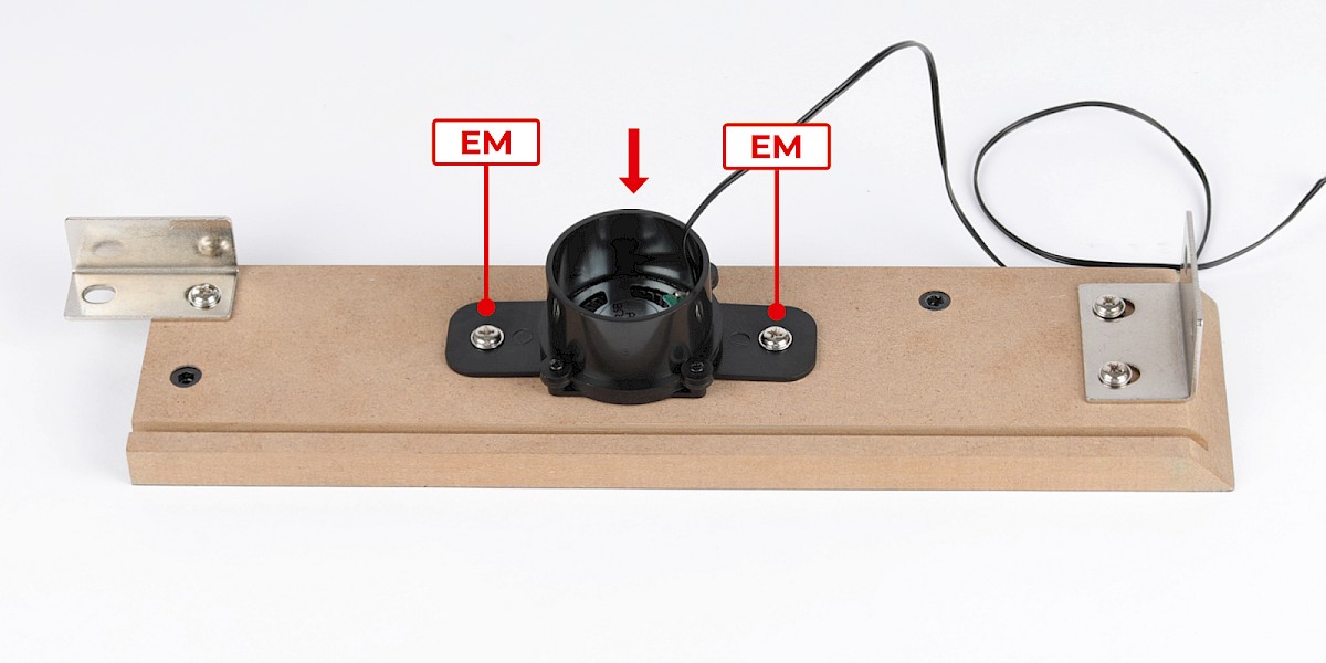
Step 2
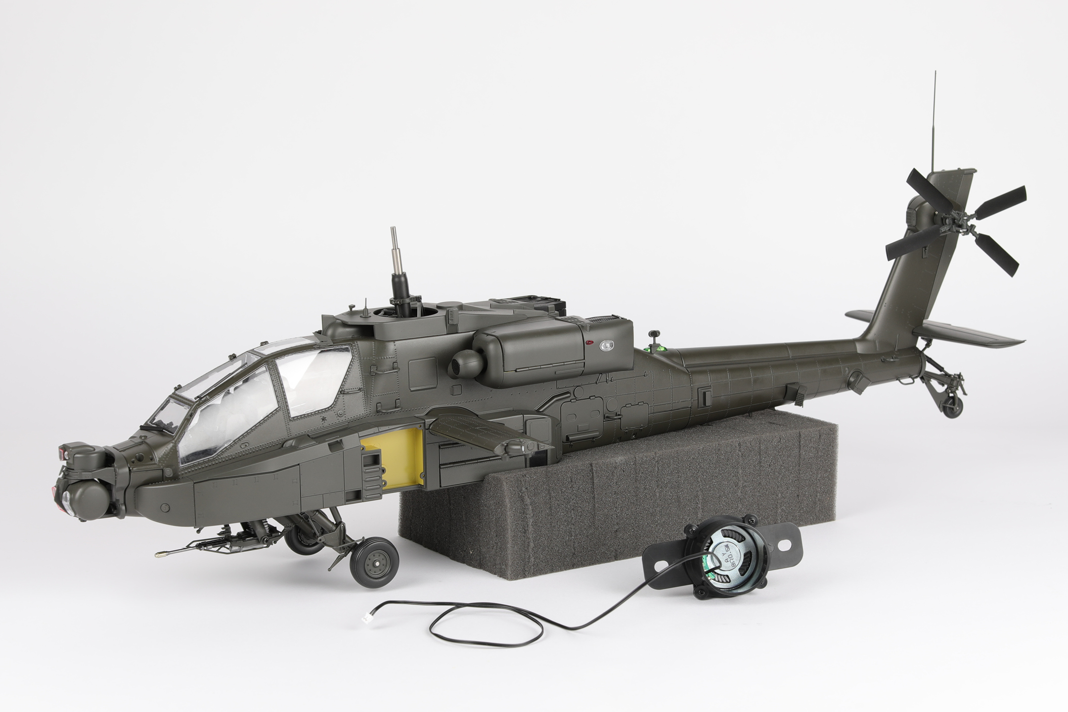
Fit the speaker (stage 89) to the assembly.
Secure with 2x EM.
Step 3
Fit the assembly to the display base frame (stage 88).
Secure with 1x EM.
Step 4
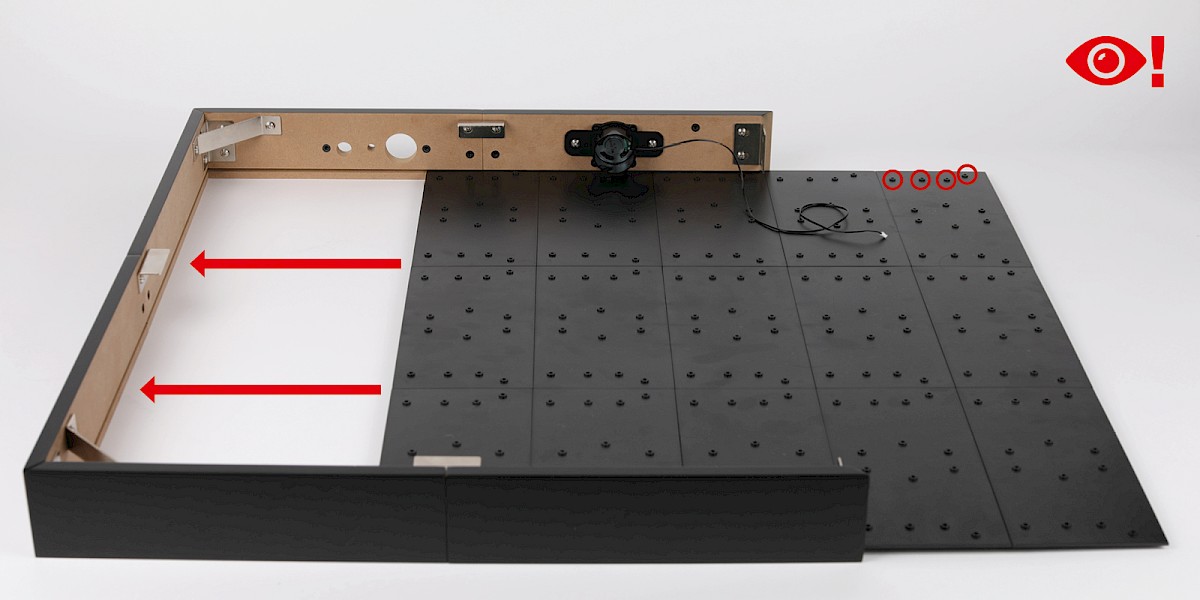
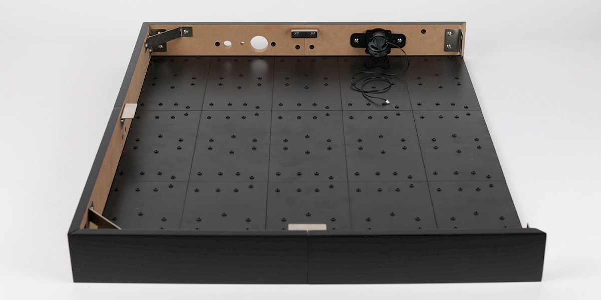
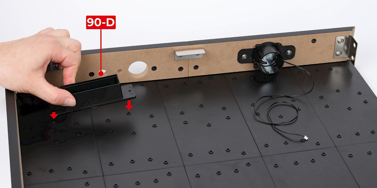
Slide the bottom of the display base (stage 87) into the frame.
Make sure the parts are in the orientation shown.
Step 5
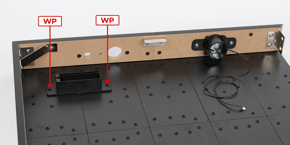
Fit 90-D to the assembly.
Secure with 2x WP.
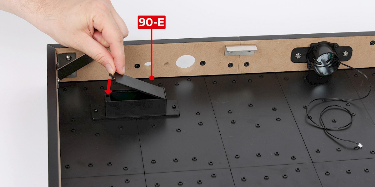
Step 6
Fit 90-E to 90-D.
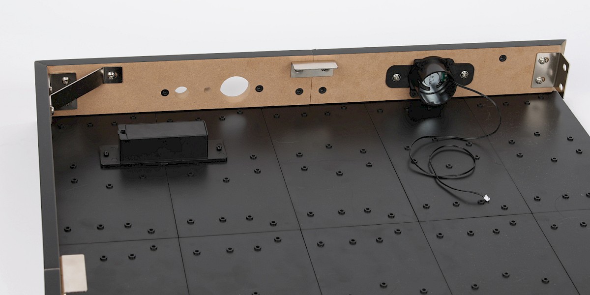
STAGE COMPLETE
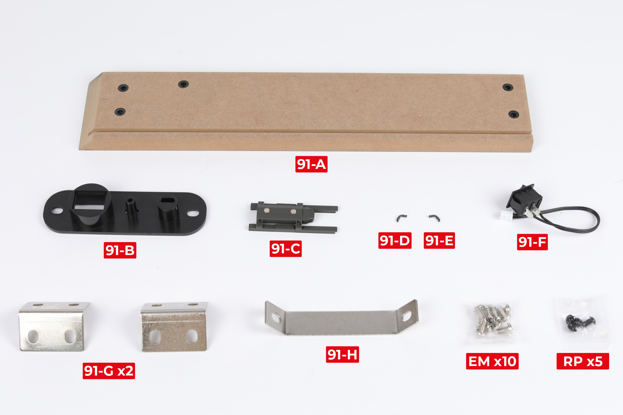
PARTS LIST
| 91-A | 91-F |
| 91-B | 91-G x2 |
| 91-C | 91-H |
| 91-D | EM x10 |
| 91-E | RP x5 |
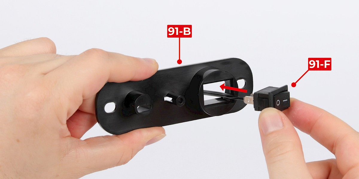
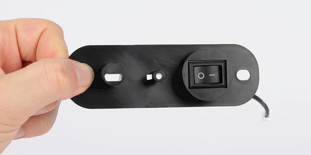
Step 1
Fit 91-F into 91-B.
Step 2
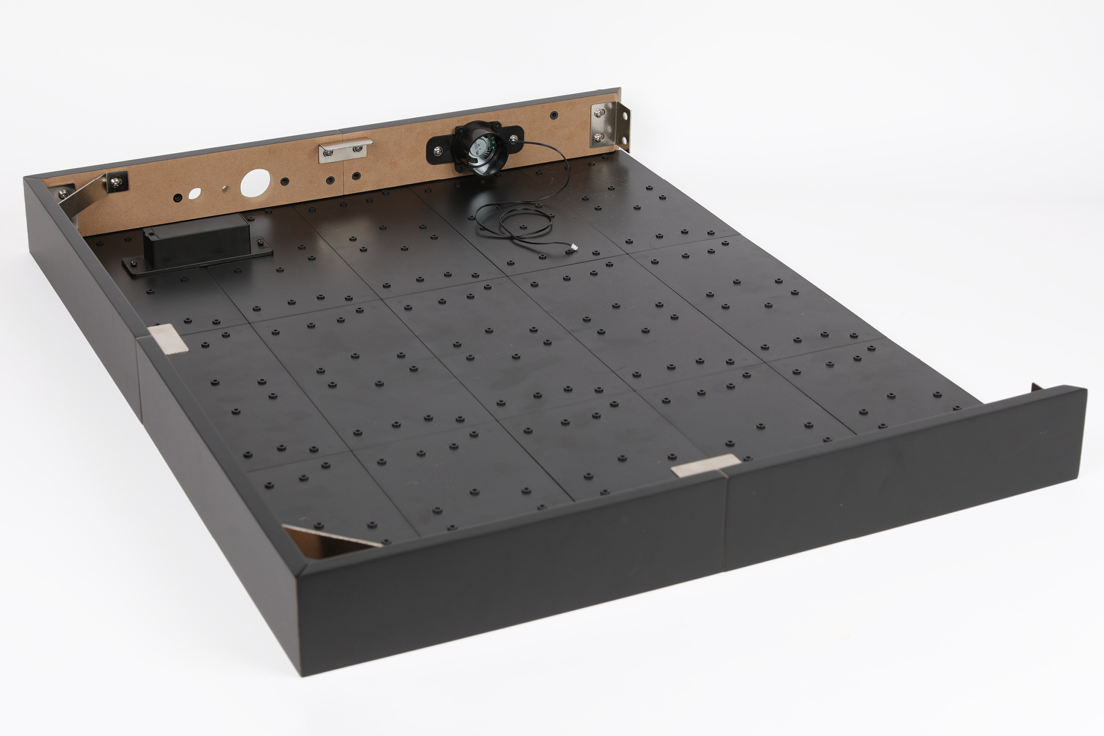
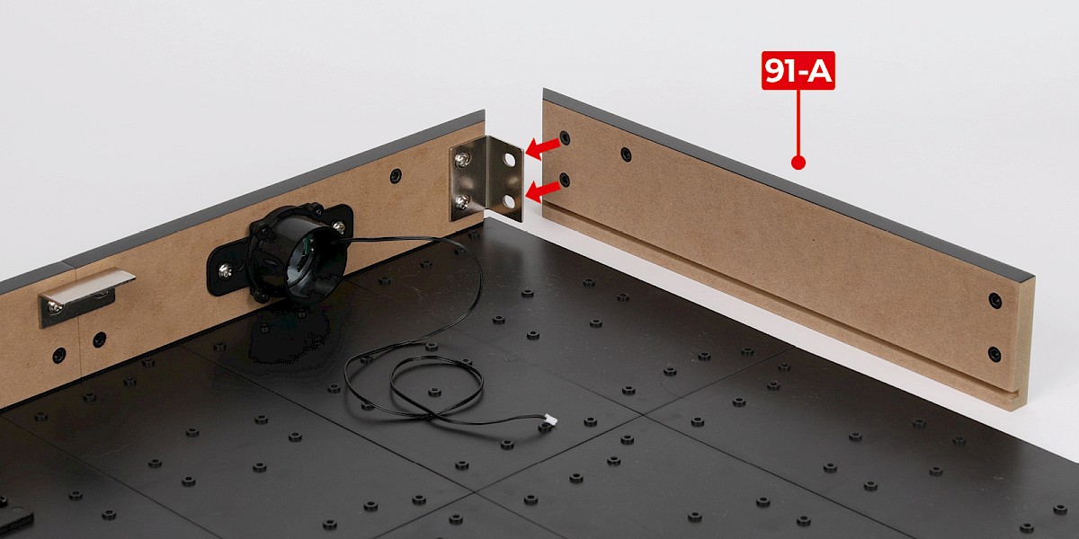
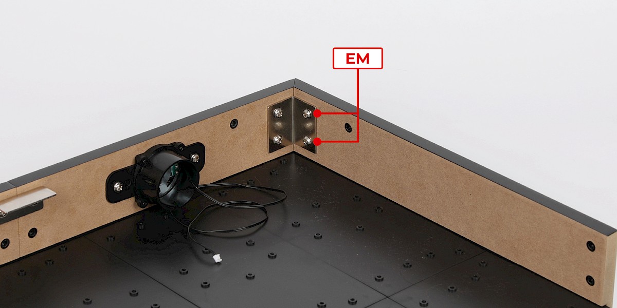
Fit 91-A to the display base assembly (stage 90).
Secure with 2x EM.
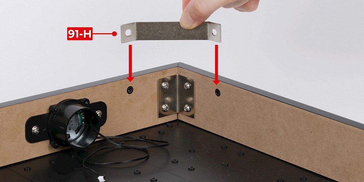
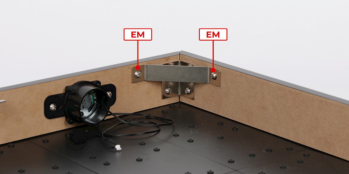
Step 3
Fit 91-H to the assembly.
Secure with 2x EM.
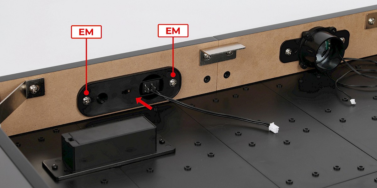
Step 4
Fit the power switch (step 1) to the assembly.
Secure with 2x EM.
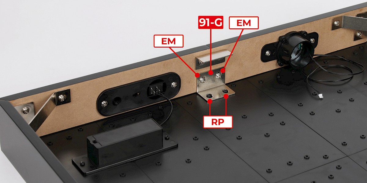
Step 5
Fit 91-G to the assembly. Secure with 2x EM and 2x RP.
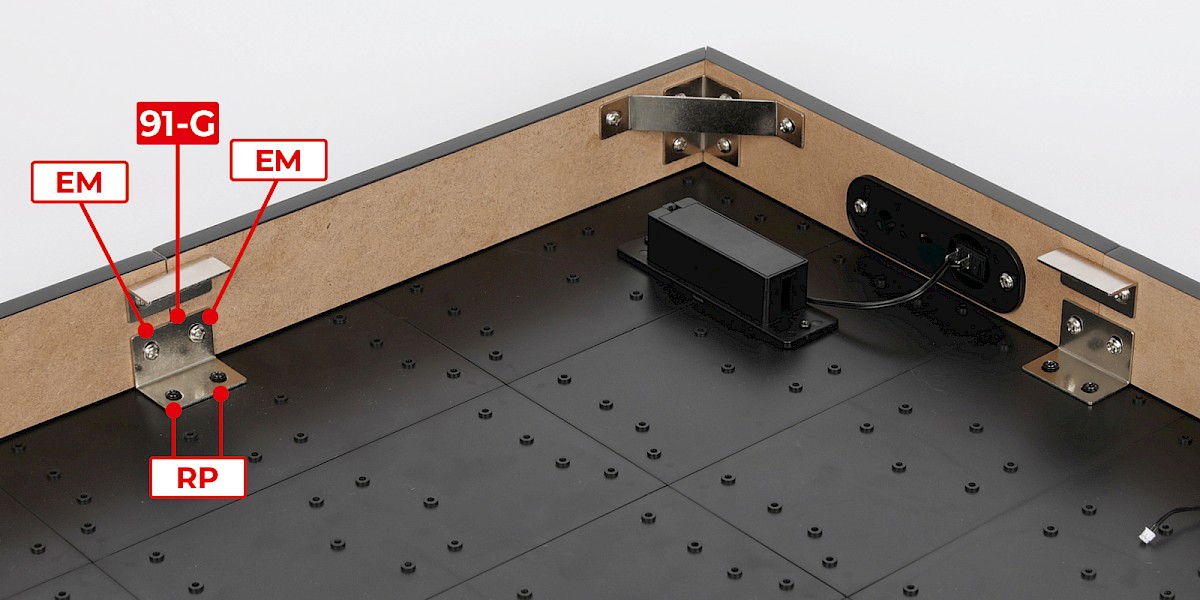
Fit the other 91-G to the assembly as shown. Secure with 2x EM and 2x RP.
Step 6
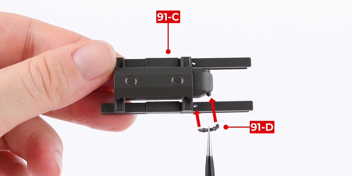
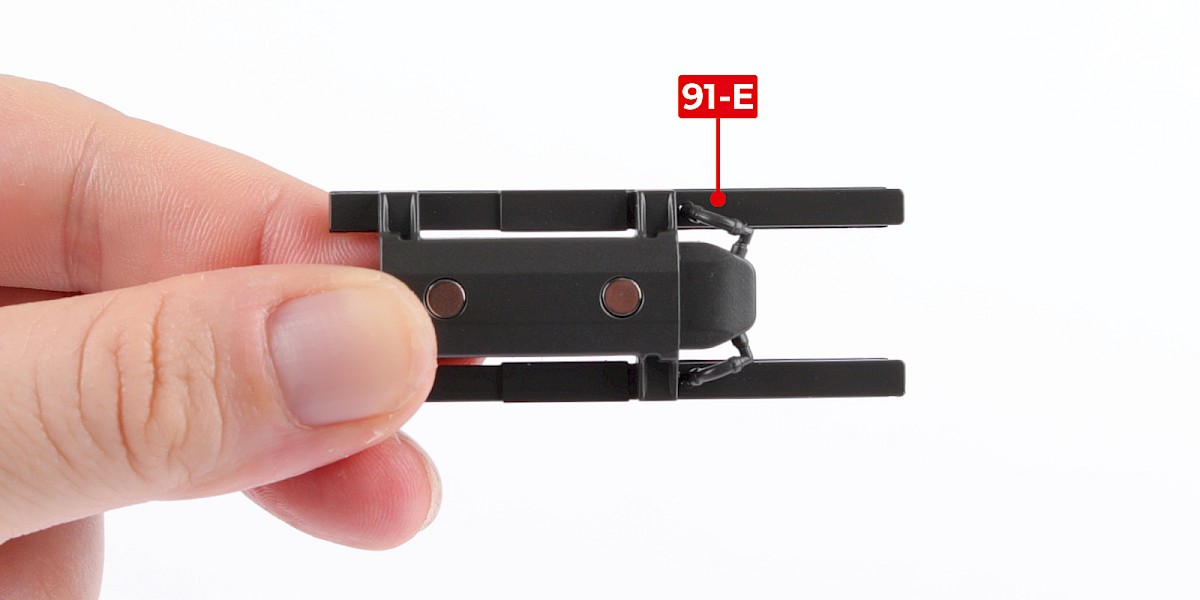
You will now assemble an M299 launcher with Spike missiles.
Fit 91-D to 91-C.
Fit 91-E to the assembly.
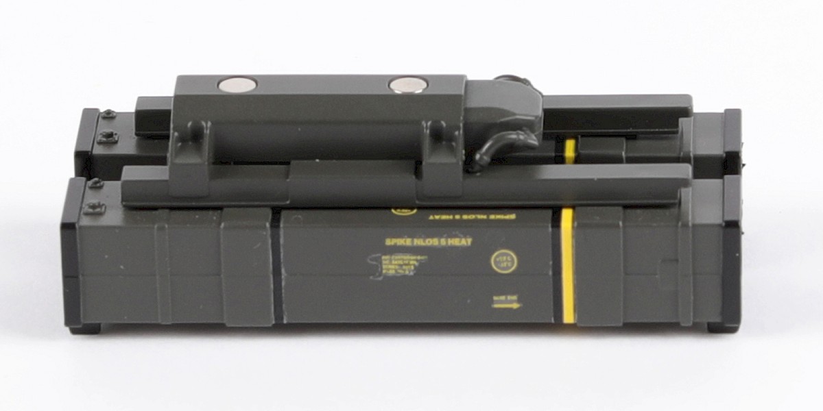
Step 7
Fit the assembly to two Spike missile launchers (stage 31).

Step 8
Cut the decals outlined in red from 85-K.

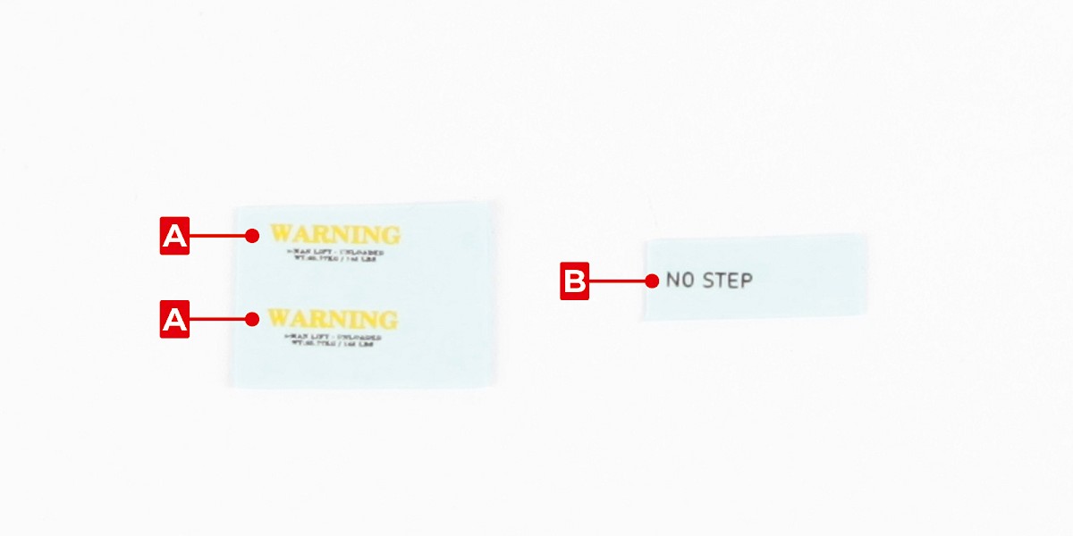
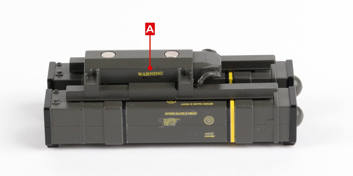
Step 9
Apply decals A to the sides of the assembly.

Step 10
Apply decal B to the front of the assembly.

STAGE COMPLETE
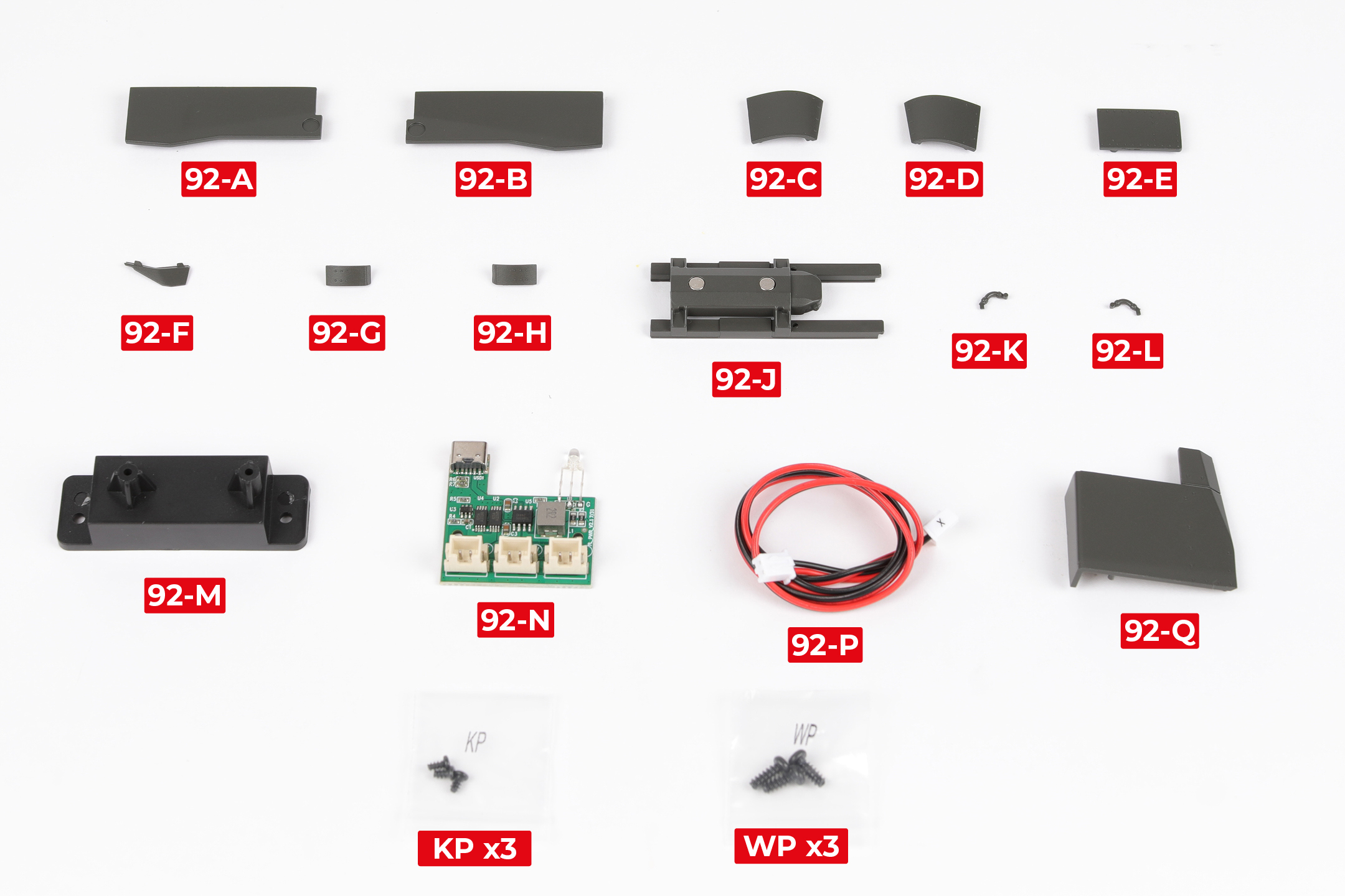
PARTS LIST
| 92-A | 92-G | 92-N |
| 92-B | 92-H | 92-P |
| 92-C | 92-J | 92-Q |
| 92-D | 92-K | 92-R |
| 92-E | 92-L | KP x3 |
| 92-F | 92-M | WP x3 |
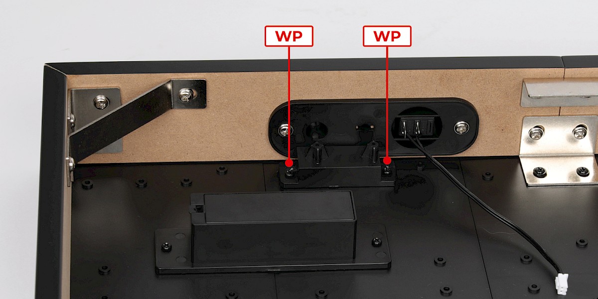
Step 1
Fit 92-M to the display base assembly (stage 91).
Secure with 2x WP.

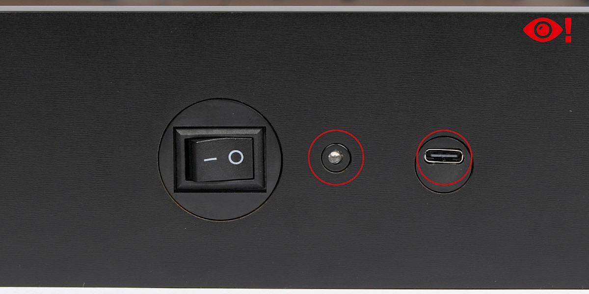
Step 2
Fit 92-N to the assembly.
The LED and USB port should look like this once fitted.
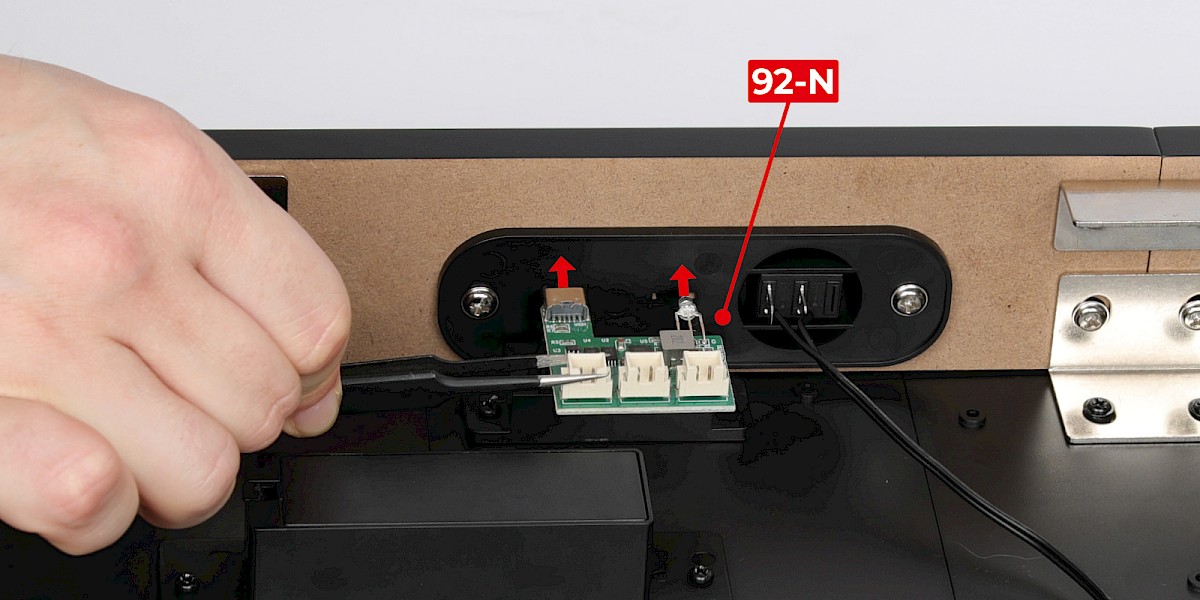
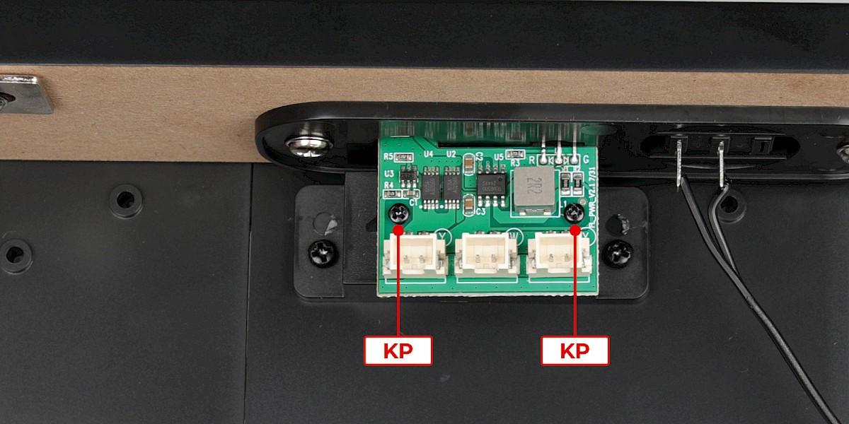
Step 3
Secure with 2x KP.
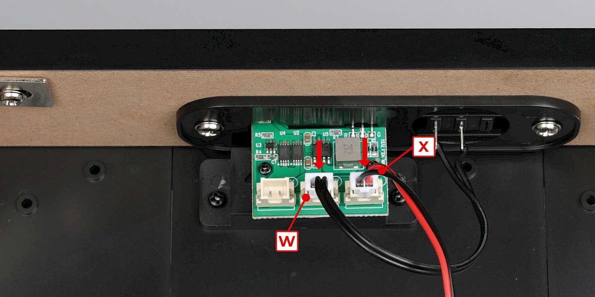
Plug cables marked "W" and "X" into the corresponding sockets.
Step 4
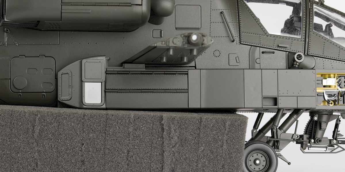
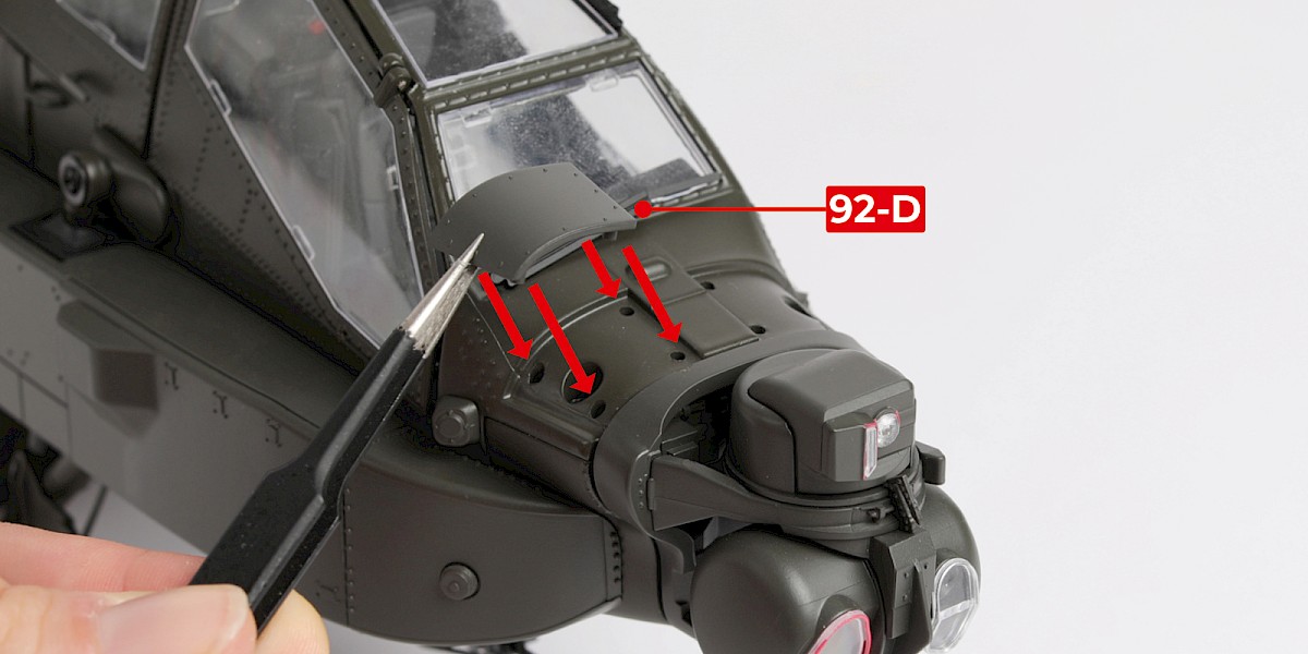
You will now fit panels to the fuselage.
Fit 92-D to the fuselage (stage 89).
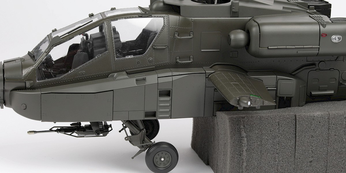
Step 5
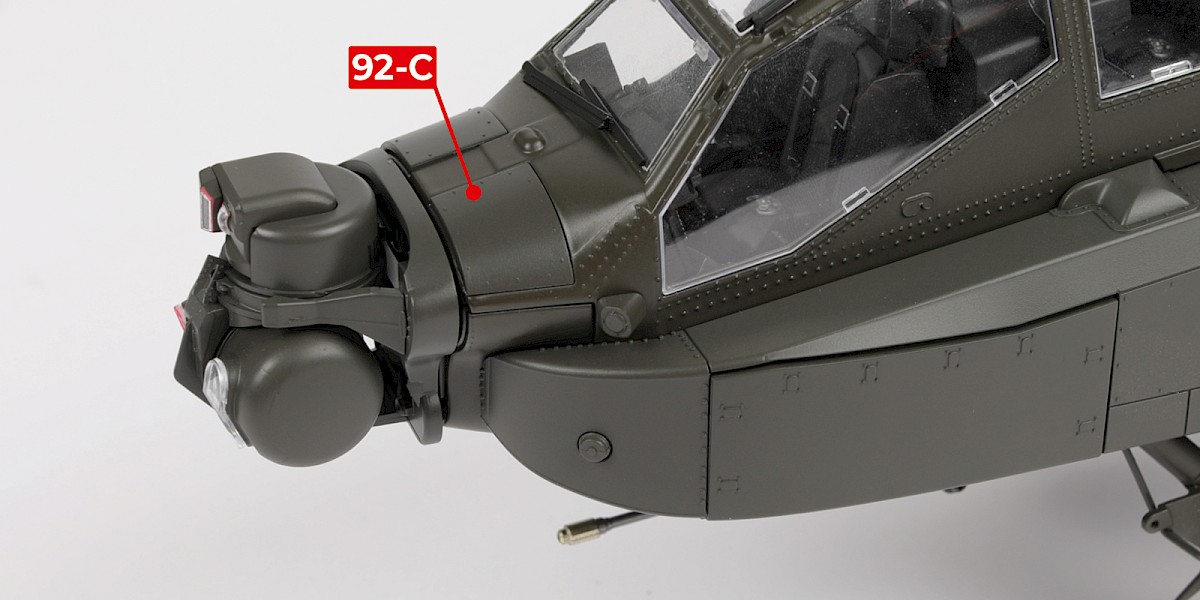
Fit 92-C to the assembly.
Step 6
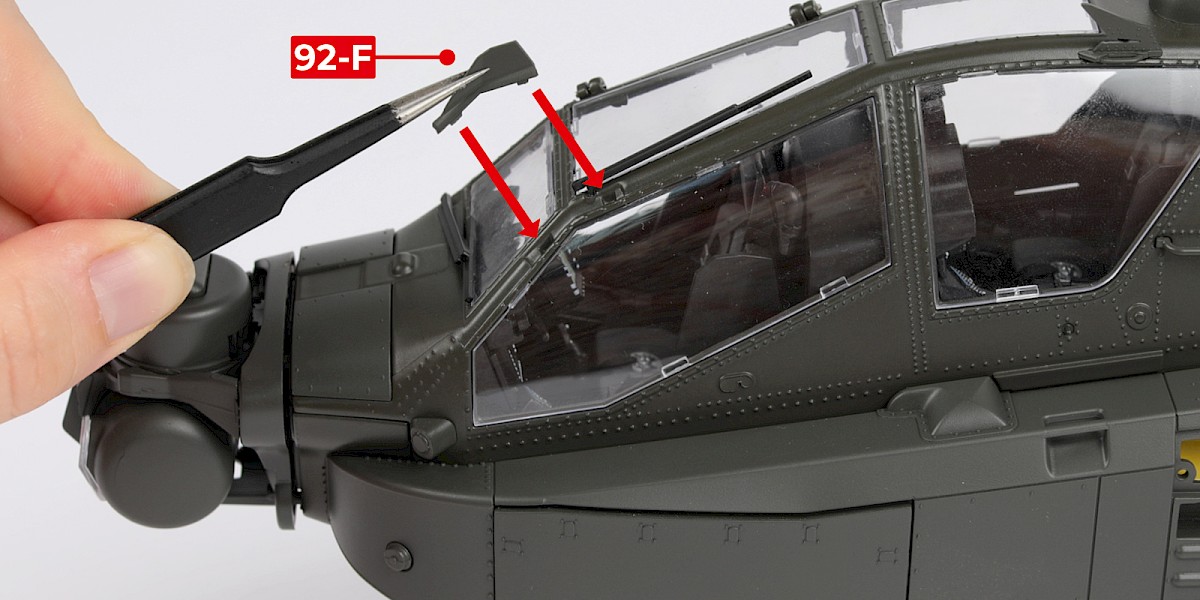
Glue 92-F to the assembly.
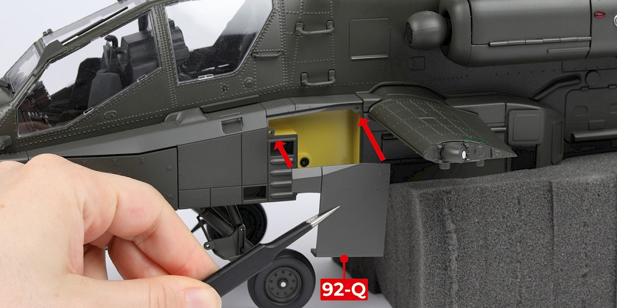
Step 7
Fit 92-Q to the assembly.
Step 8
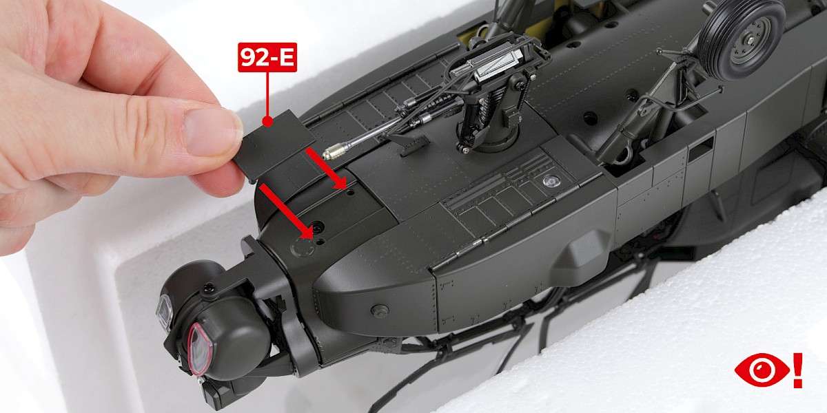
You will now work on the underside of your Apache. Please take care when turning your model over and make sure your model is properly supported.
First, fit 92-E to the assembly.
Step 9
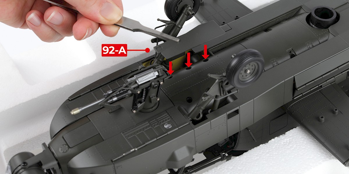
Fit 92-A and 92-B to the assembly.
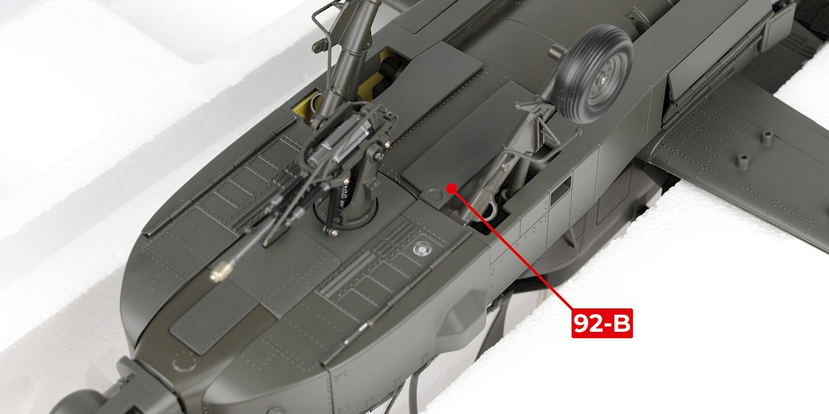
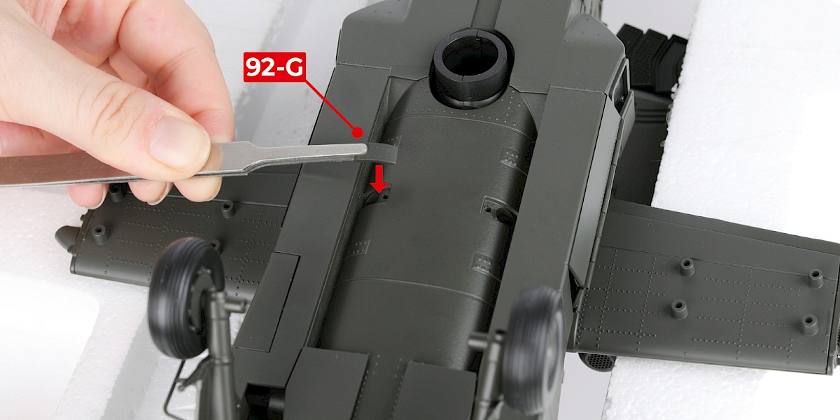
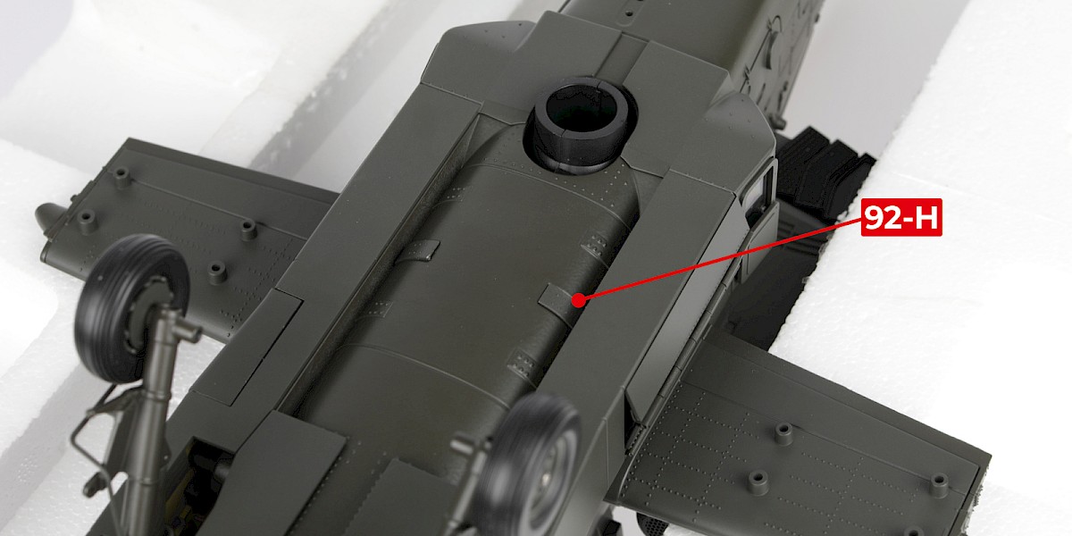
Step 10
Fit 92-G and 92-H to the assembly.
Step 11
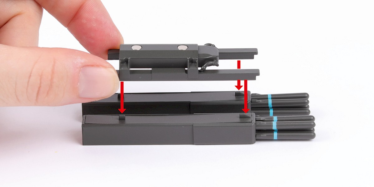
You will now assemble an M299 launcher with DAGR missiles.
Fit 92-K to 92-J.
Fit 92-L to the assembly.


Step 12
Fit the assembly to two DAGR missile launchers (stage 27 and 28).
Step 13
Cut the decals outlined in red from 85-K.

Step 14
Apply decals A to the sides of the assembly.
Step 15
Apply decal B to the front of the assembly.
STAGE COMPLETE