

Pack 12
BUILD INSTRUCTIONS
Advice from the experts
Spare screws are included with each part. Occasionally, you may be instructed to keep spare or unused screws for a later stage. Keep these spares in a safe place and label them correctly.
Please make sure you don’t mix up the screws. They look quite similar, but the threads do vary slightly. Using the wrong screws may damage the parts. Only use the correct size screwdriver that fits the screw head firmly.
When securing parts together using multiple screws, fit each screw loosely to ensure all the parts are correctly aligned before gently tightening them firmly, but not overtight, in the order in which you placed them.
The screwdriver can be magnetized by stroking it with a magnet (fridge magnet, etc.) enabling it to hold the screws and make assembly easier.
If a screw is tight going into a metal part, do not force it as you may shear the head off. Remove it and put a tiny smear of Vaseline, soap or light oil on the thread. That will lubricate it and make it easier to tighten.
Some parts will require a little glue for assembly. Please apply glue sparingly and use a cocktail stick so that you don’t use too much nor apply the glue too heavily. We recommend superglue gel or Extra Thin Liquid modeling glue. Where possible, parts should be test-fitted in place before gluing.
Make sure you have good ventilation when using adhesives and to replace caps firmly.
Use a magnet to help find screws that have fallen on the floor.
Use masking tape to hold parts temporarily in place.
Cut parts from a sprue (framework) with side cutters or a craft knife. Side cutters tend to be easiest.
During the course of this build, you will receive many pieces that you will assemble immediately – following the instructions in the corresponding stage – and other pieces that you should store safely to one side, for use in future assembly stages.
Always protect the paint finish on components by placing a cutting mat, sheet of white paper or soft cloth on your work surface.
When plugging cables in, ensure the power is switched off. Tweezers can be used to fit the PVC cables by gripping carefully around 5mm from the end of the cable. If a cable needs to be removed from a socket, do not pull on the cable as this could damage the connection. Grip the plug with tweezers to remove it.
Left and Right! When building your AH-64 Apache, the left- or right-hand side refers to that side as if you are sitting in the cockpit.
![]() When you see this symbol, pay attention to the instruction text in bold and check the orientation of the parts in the image as this will be particularly important for assembly in later stages.
When you see this symbol, pay attention to the instruction text in bold and check the orientation of the parts in the image as this will be particularly important for assembly in later stages.
WARNING: Some parts are assembled using magnets. These magnets can cause serious injury if they are swallowed. Keep away from children. If you suspect a magnet has been swallowed, seek medical help straight away.
This is not a toy. Not suitable for children under 14 years old due to small parts. Adult supervision required.
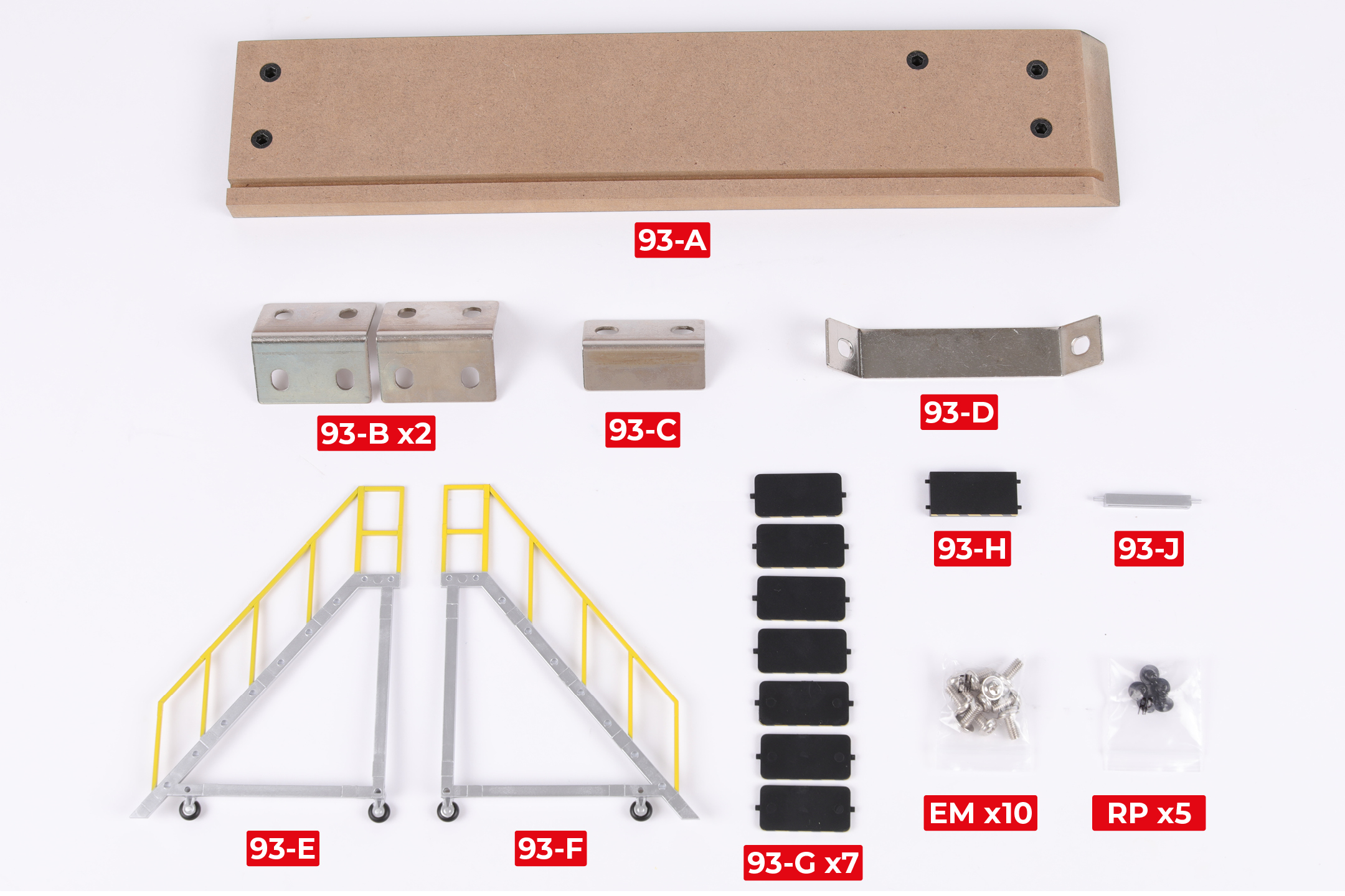
PARTS LIST
| 93-A | 93-H |
| 93-B x2 | 93-J |
| 93-C | EM x10 |
| 93-D | RP x5 |
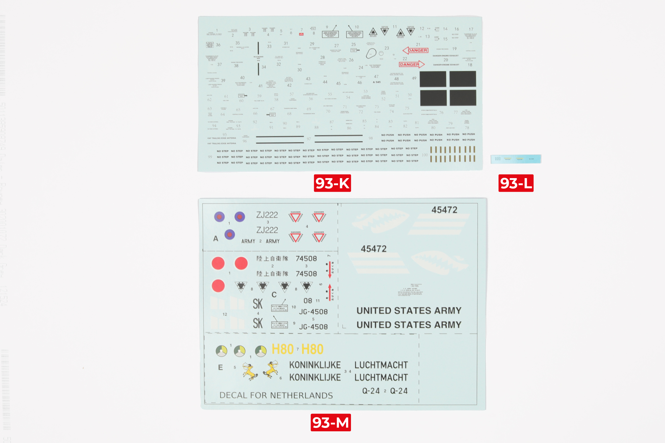
| 93-E | 93-K |
| 93-F | 93-L |
| 93-G x7 | 93-M |
You will also find spare parts in your pack: a second decal sheet (93-K), a spare rail (83-F) and a complete missile crate.
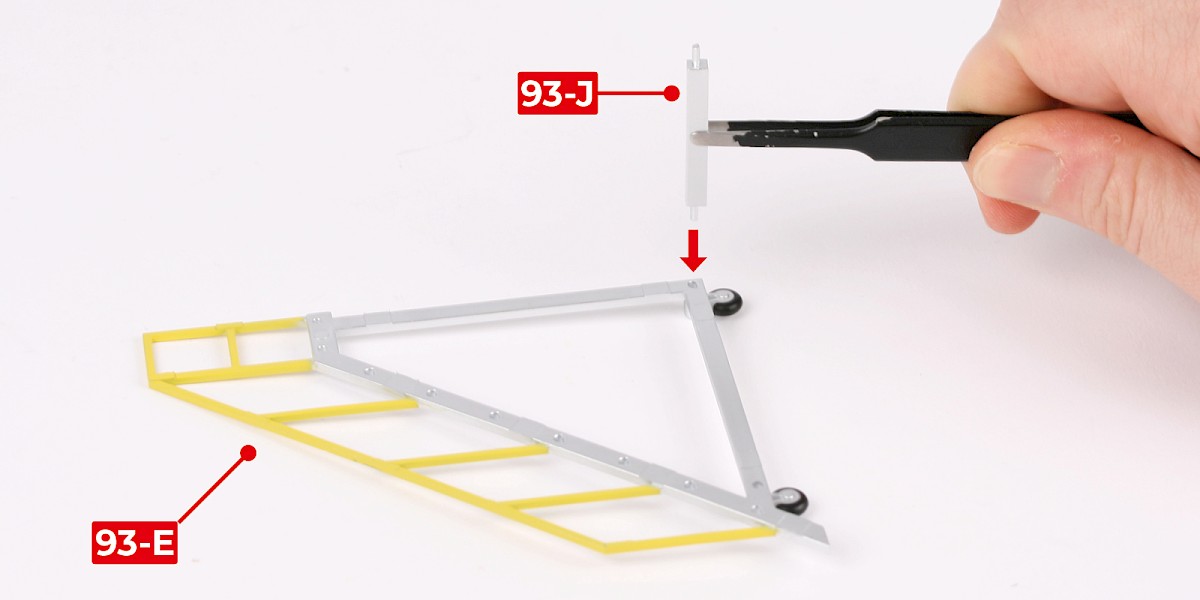
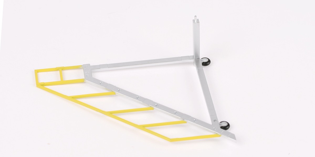
Step 1
Glue 93-J to 93-E.
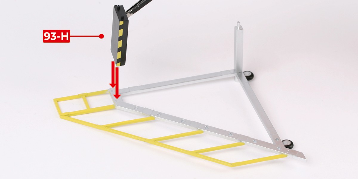
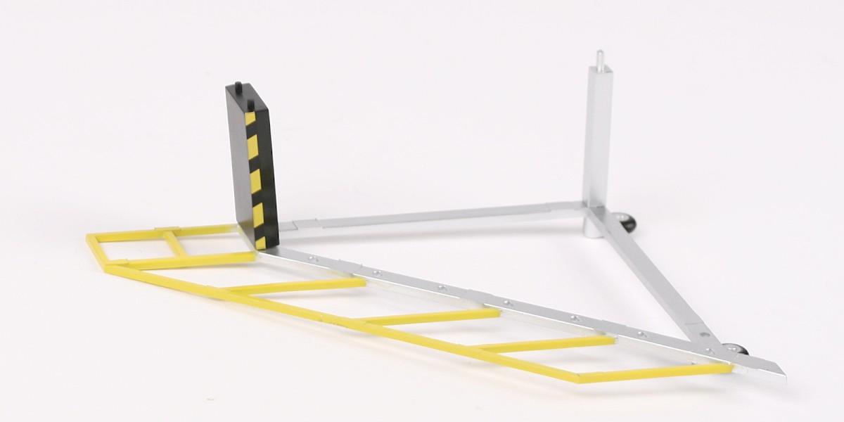
Step 2
Glue 93-H to the assembly.
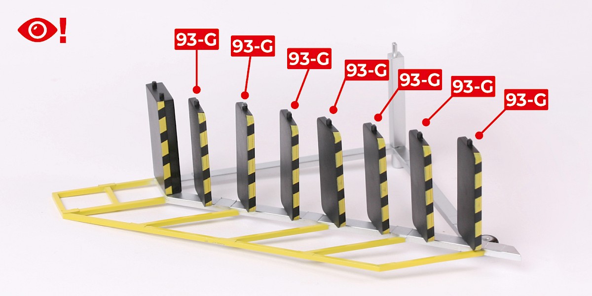
Step 3
Continue to glue 93-G to the assembly.
Note: Do not allow the glue to dry. You may need to adjust these parts in the next step.
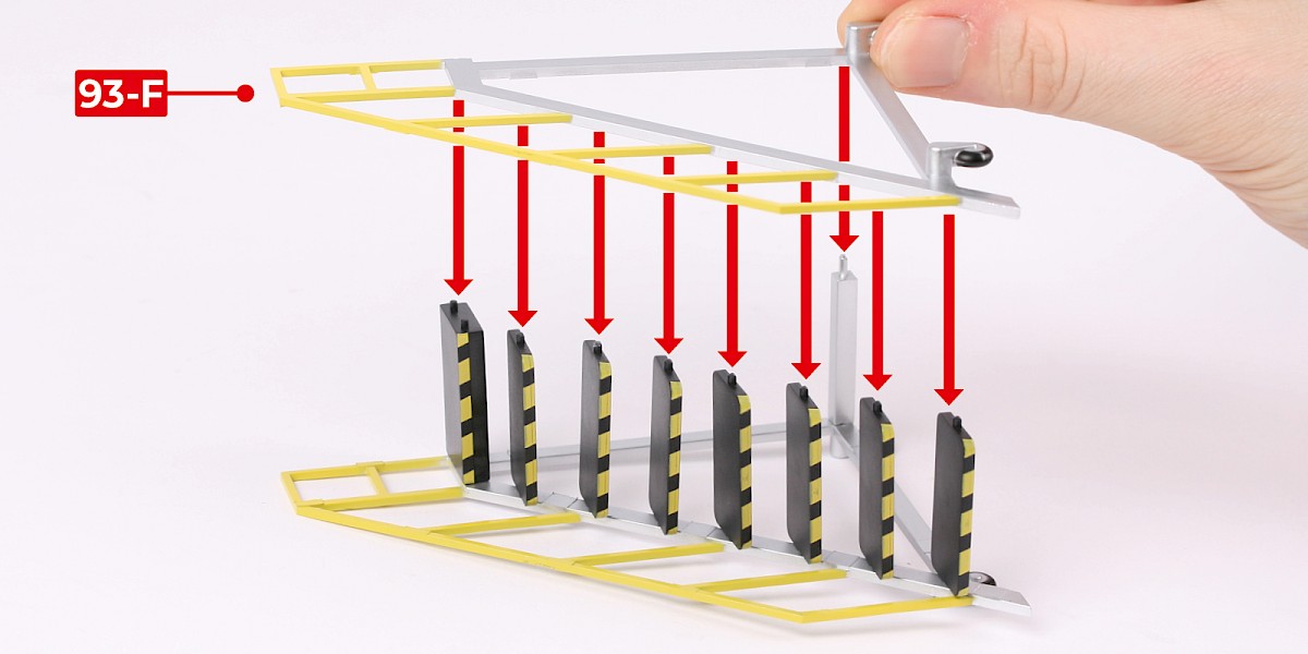
Step 4
Glue 93-F to the assembly.
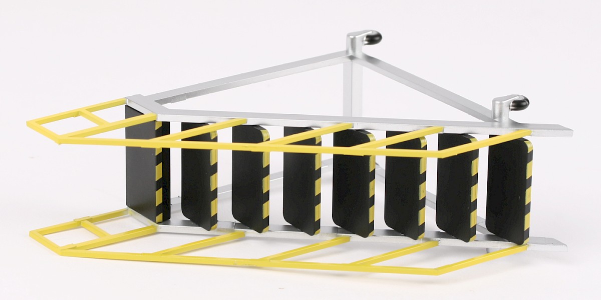
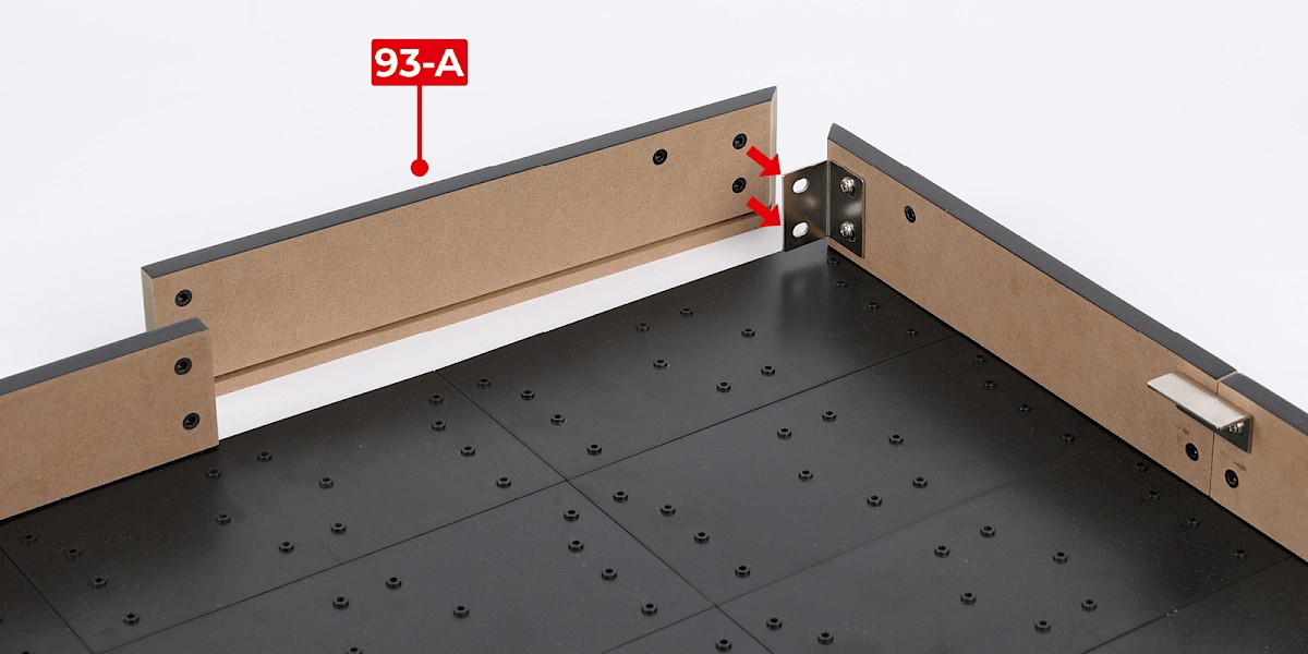
Step 5
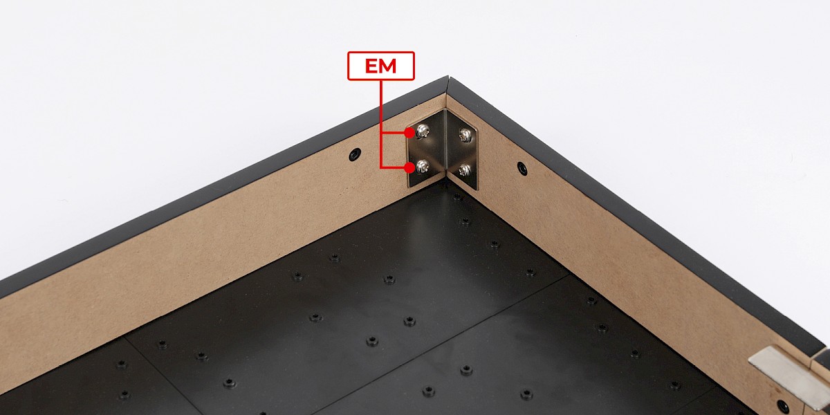
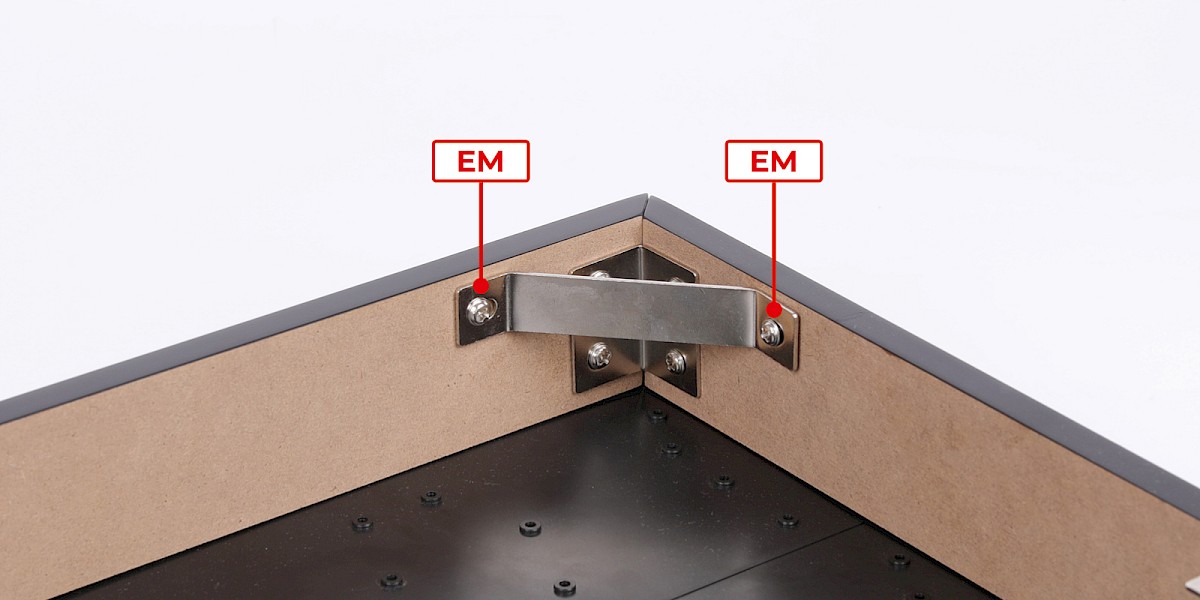
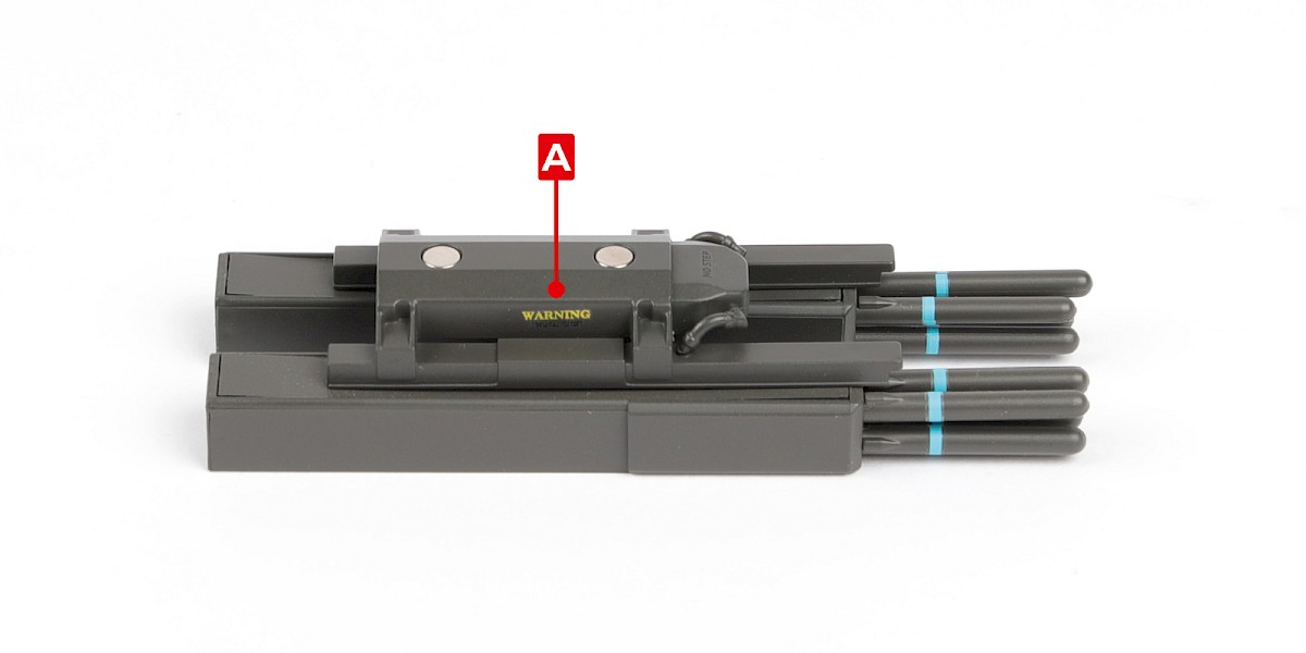
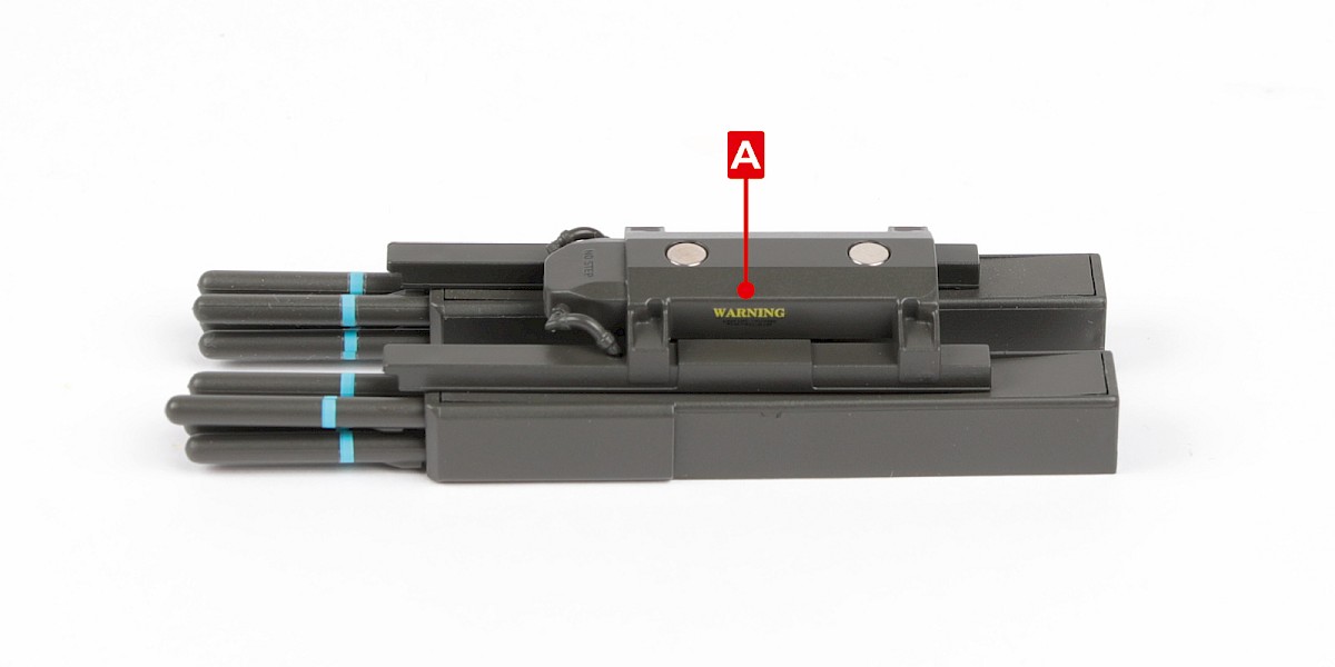
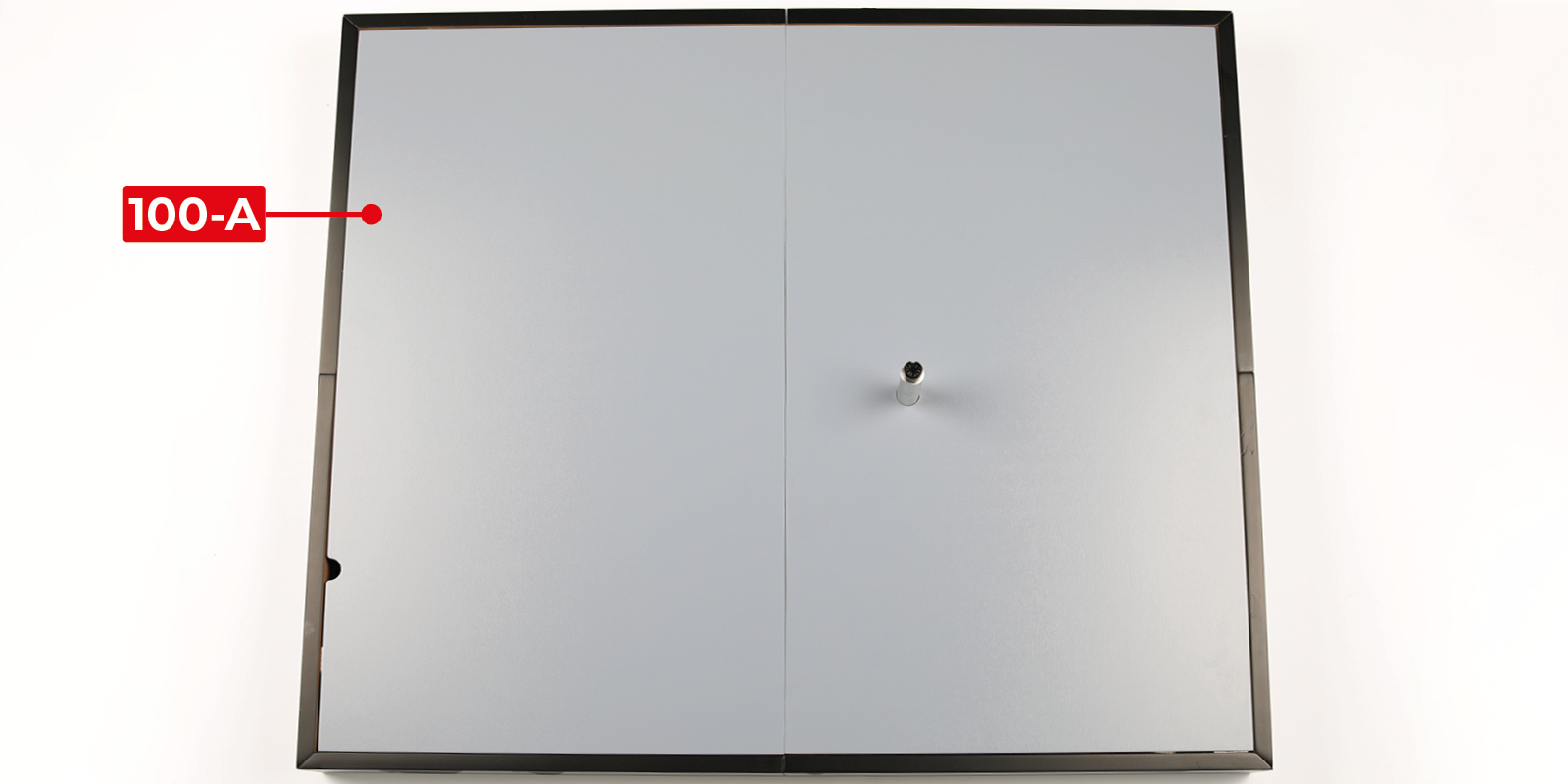
Fit 93-A to the display base assembly (stage 92).
Secure with 2x EM.
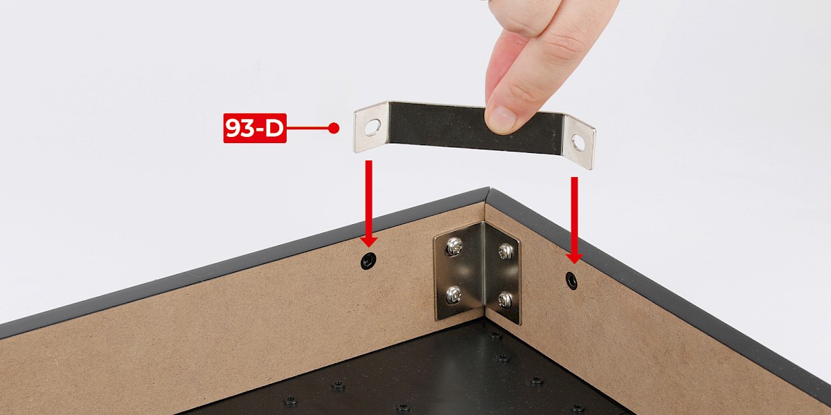
Step 6
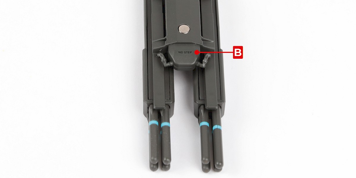
Fit 93-D to the assembly.
Secure with 2x EM.
Step 7
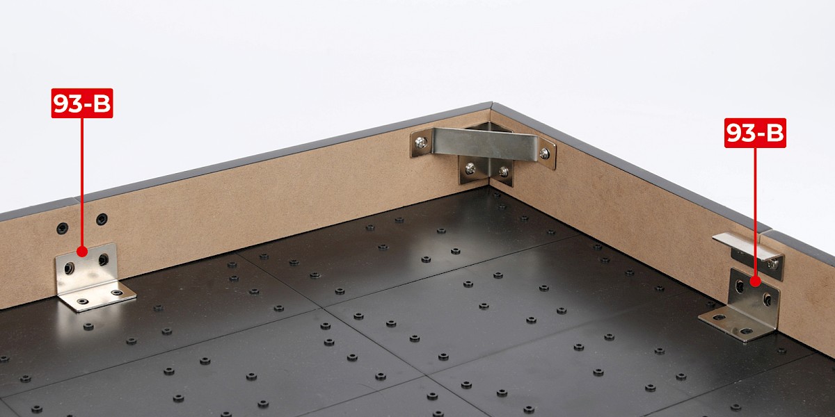
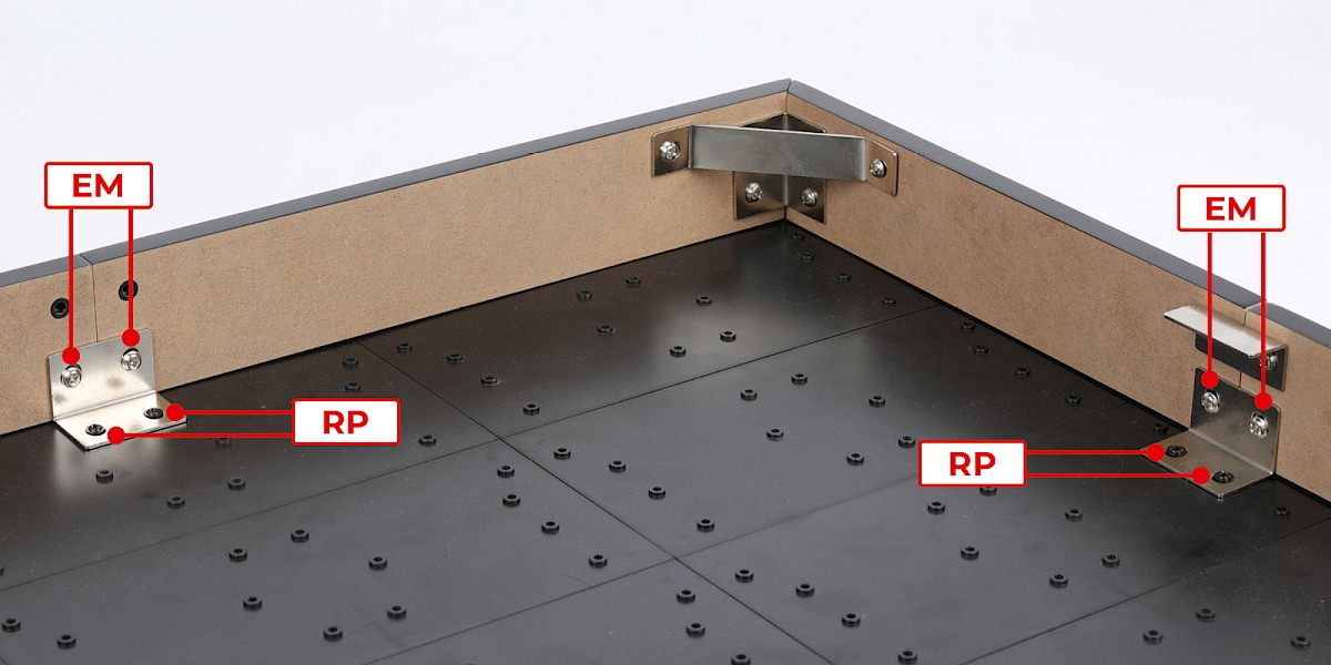
Fit two 93-B to the assembly.
Secure with 4x EM and 4x RP.
Step 8
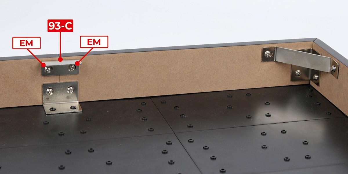
Fit 93-C to the assembly.
Secure with 2x EM.
Step 9
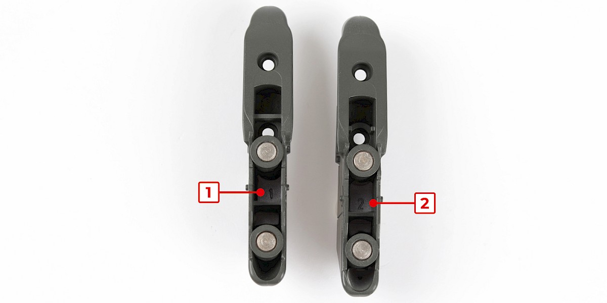
Retrieve the wing pylons (stage 40 and 42). The parts are marked with "1" and "2" as shown.
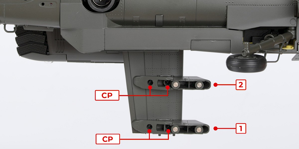
Step 10
Fit the wing pylons to the right wing as shown.
Secure the parts with 4x CP (supplied with stage 40).
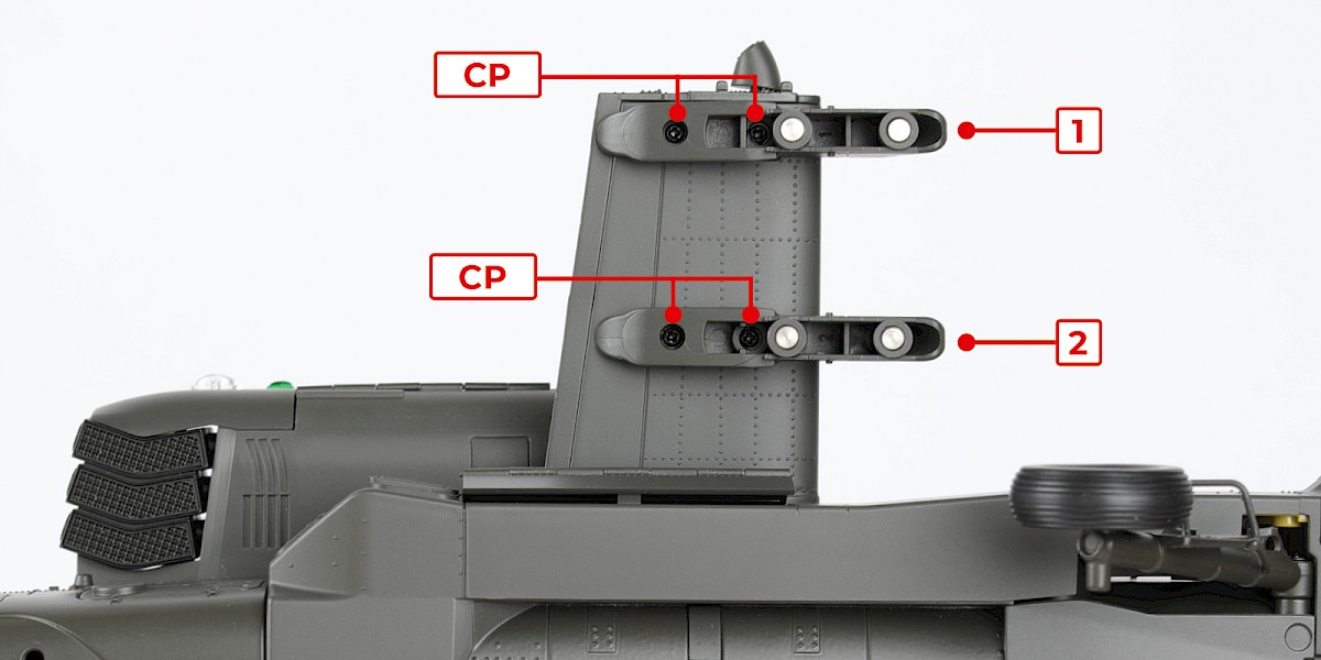
Step 11
Fit the wing pylons to the left wing as shown.
Secure the parts with 4x CP (supplied with stage 42).
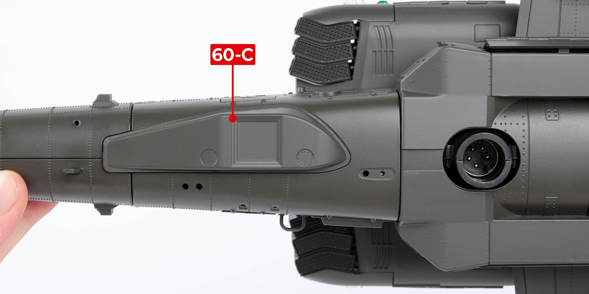
Step 12
Fit 60-C (supplied with stage 60) to the assembly.
STAGE COMPLETE
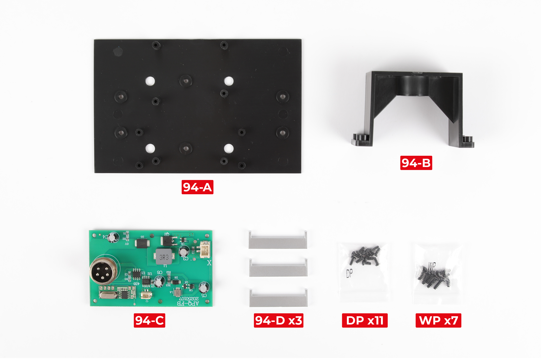
PARTS LIST
| 94-A | 94-D x3 |
| 94-B | DP x11 |
| 94-C | WP x7 |
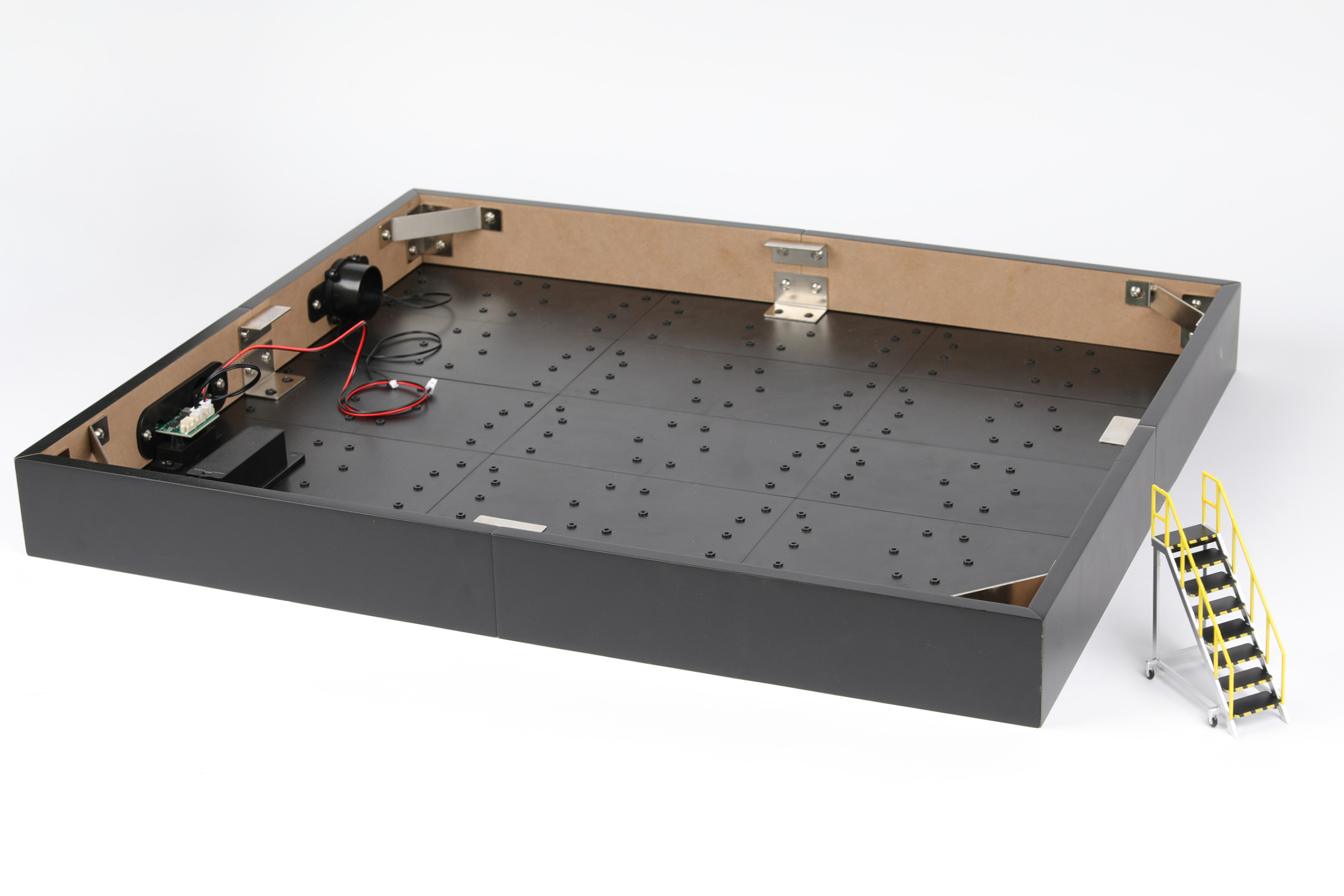
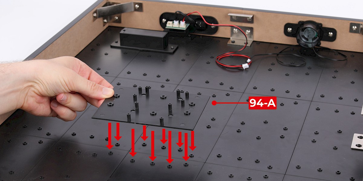
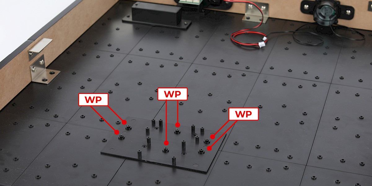
Step 1
Fit 94-A to the display base assembly (stage 93).
Secure with 6x WP.
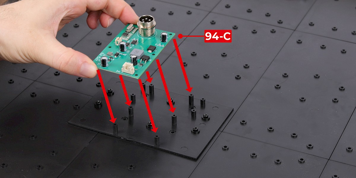
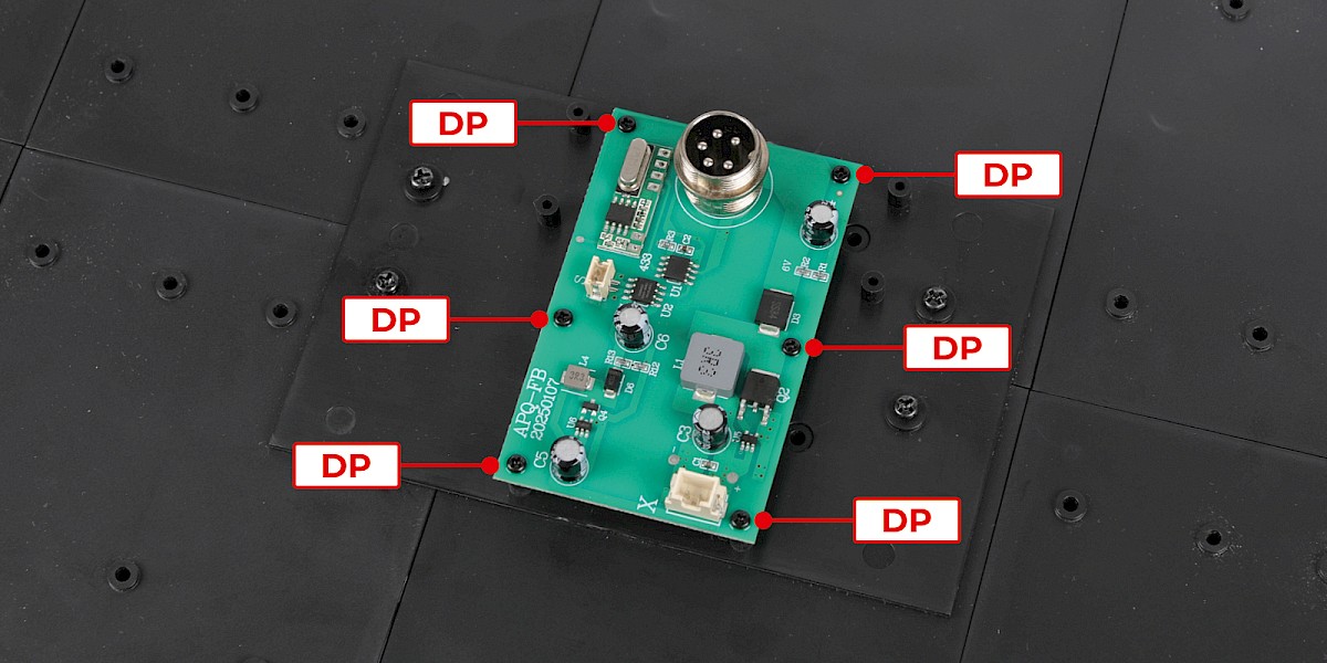
Step 2
Fit 94-C to the assembly.
Secure with 6x DP.
Step 3
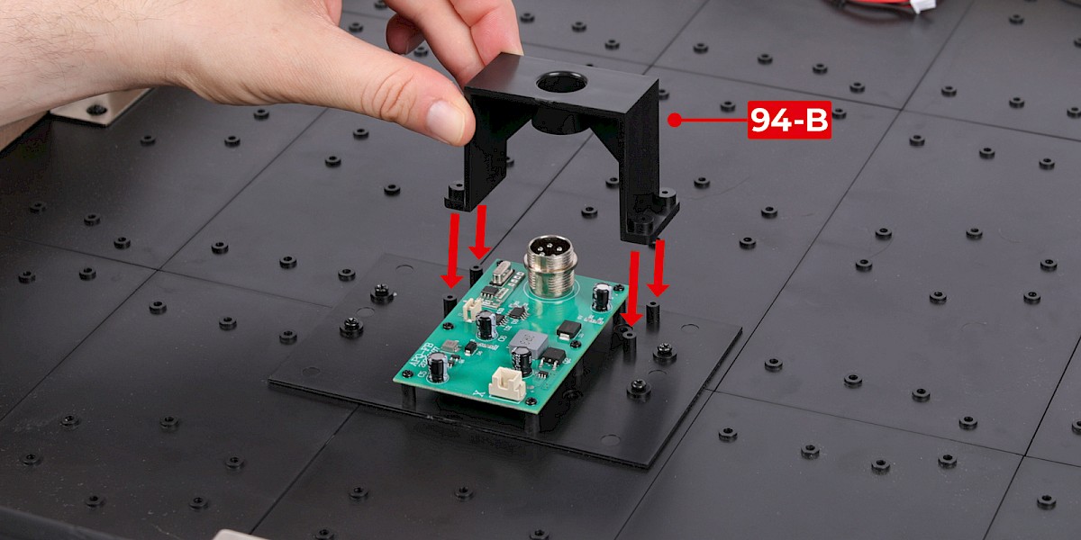
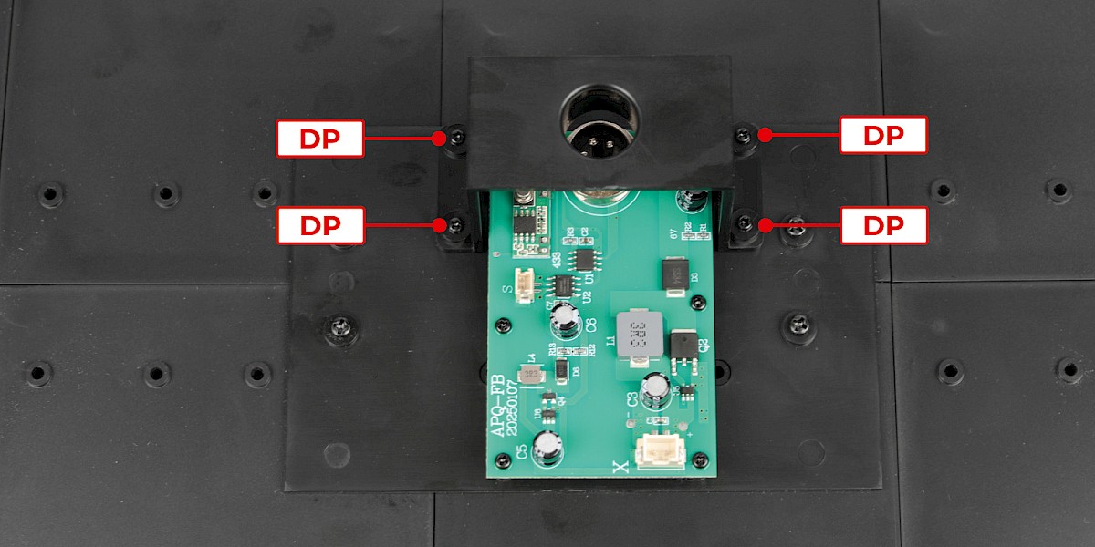
Fit 94-B to the assembly.
Secure with 4x DP.
Step 4
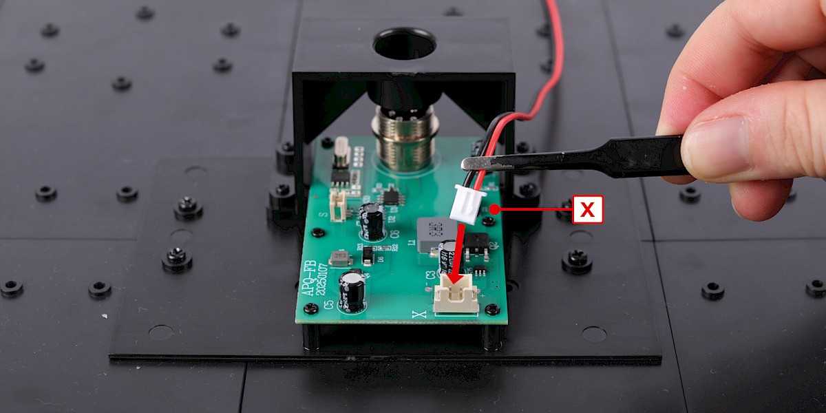
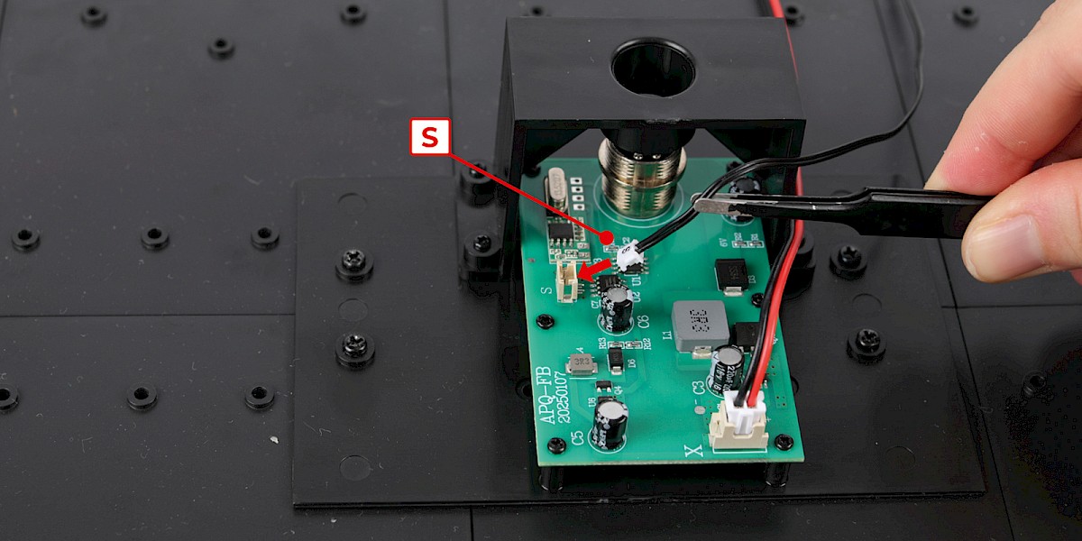
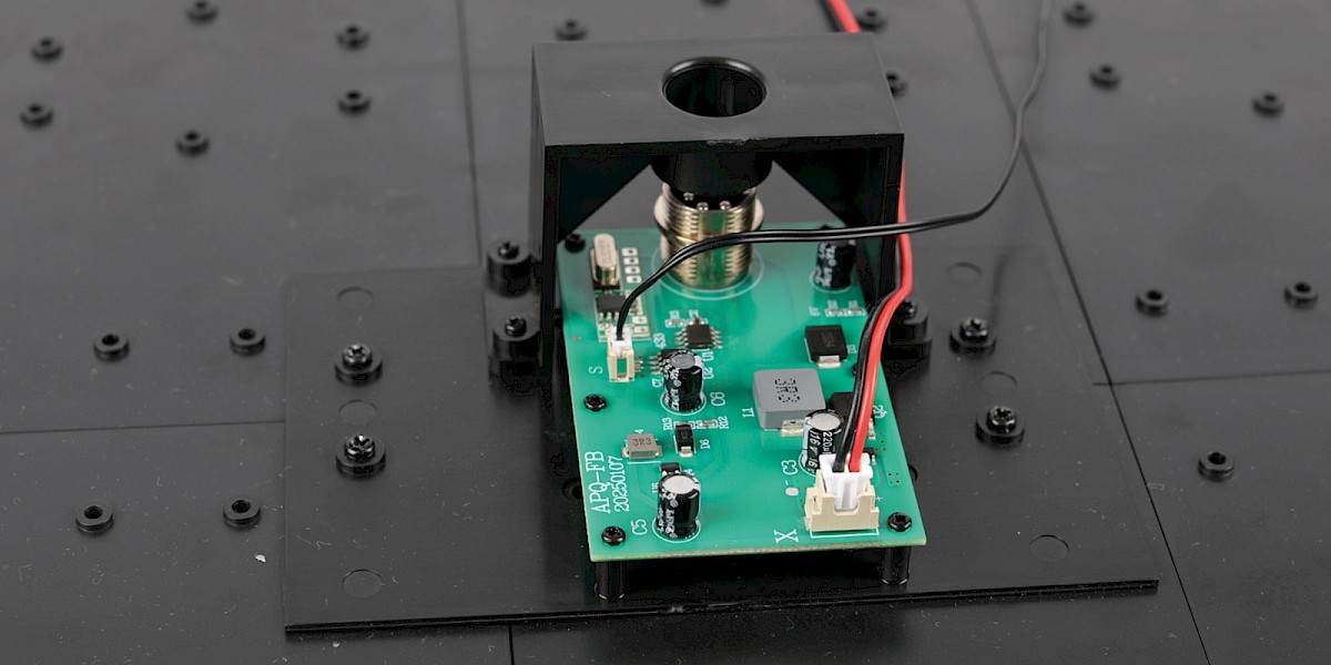
Next you will plug the cables into the sockets marked "S" and "X".
Plug the power switch cable, marked "X", into the corresponding socket.
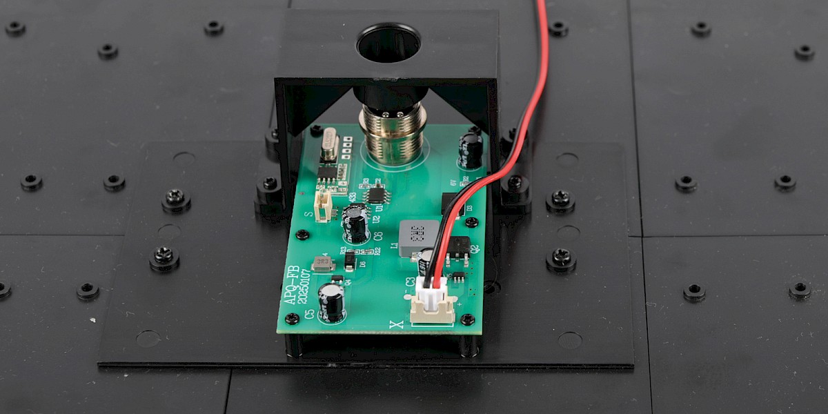
Step 5
Plug the speaker cable, marked "S", into the corresponding socket.
Step 6
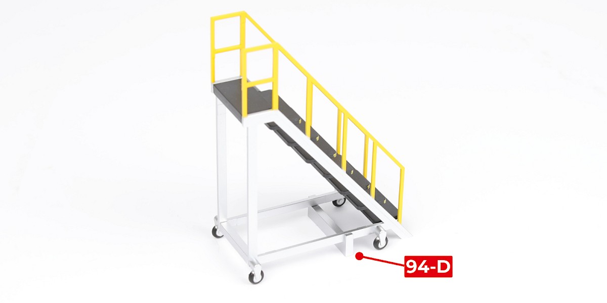
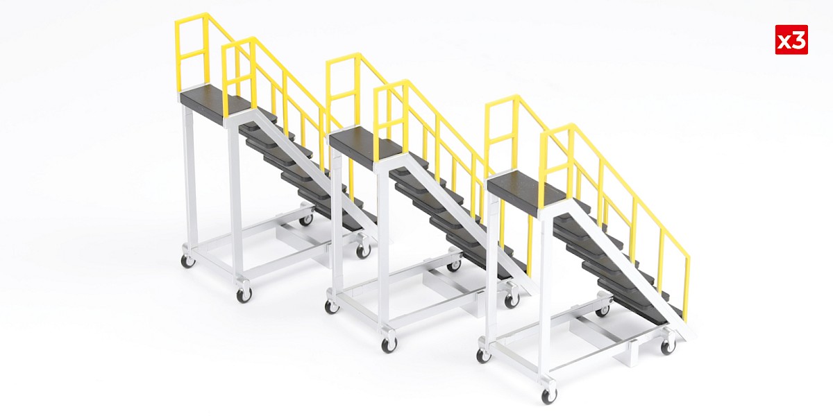
Glue 94-D to a mobile stepladder (stage 66).
Repeat to complete the mobile stepladders from stages 68 and 93.
STAGE COMPLETE
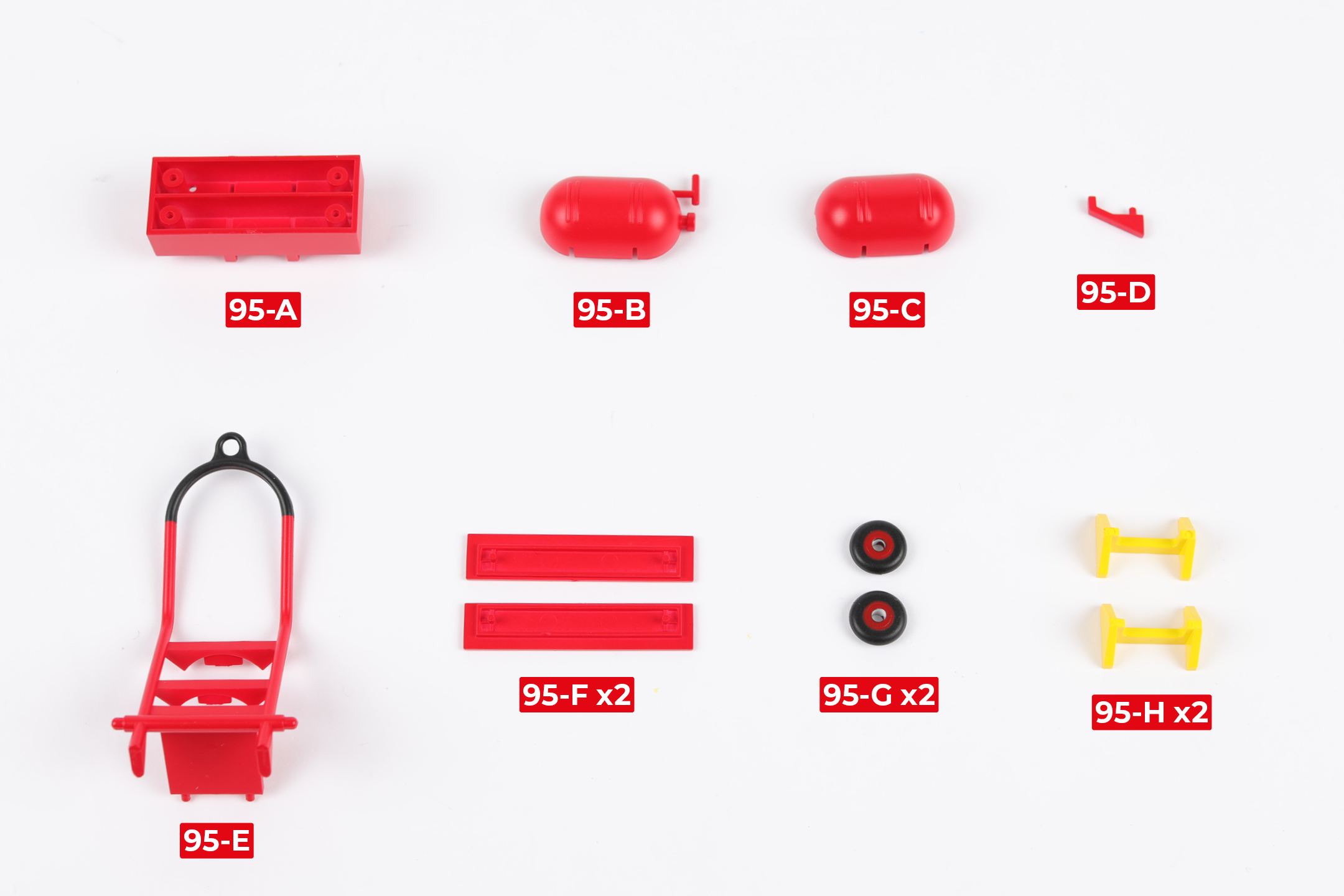
PARTS LIST
| 95-A | 95-E |
| 95-B | 95-F x2 |
| 95-C | 95-G x2 |
| 95-D | 95-H x2 |
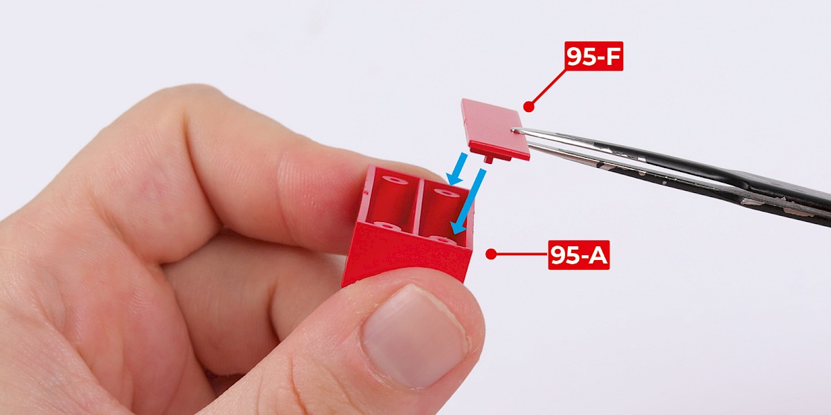
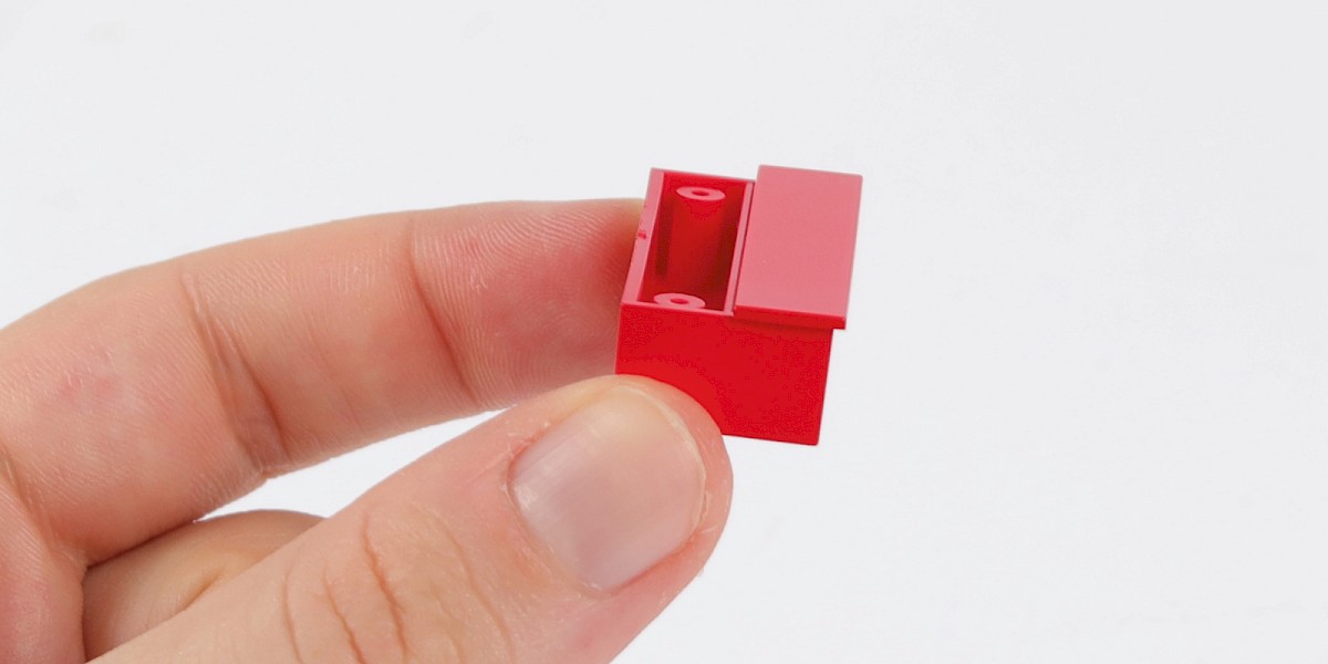
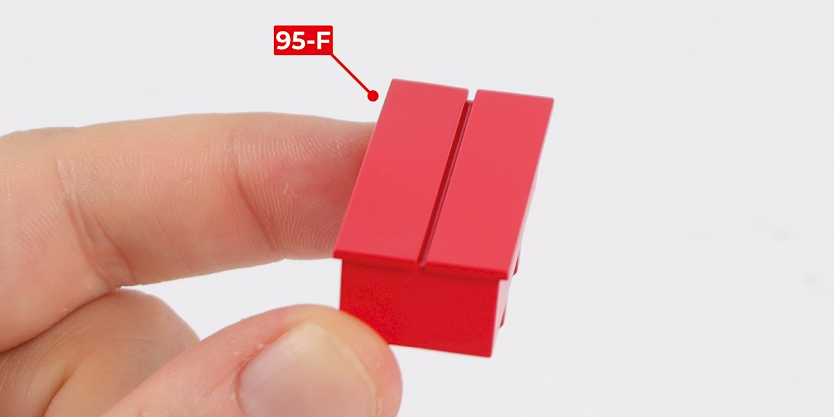
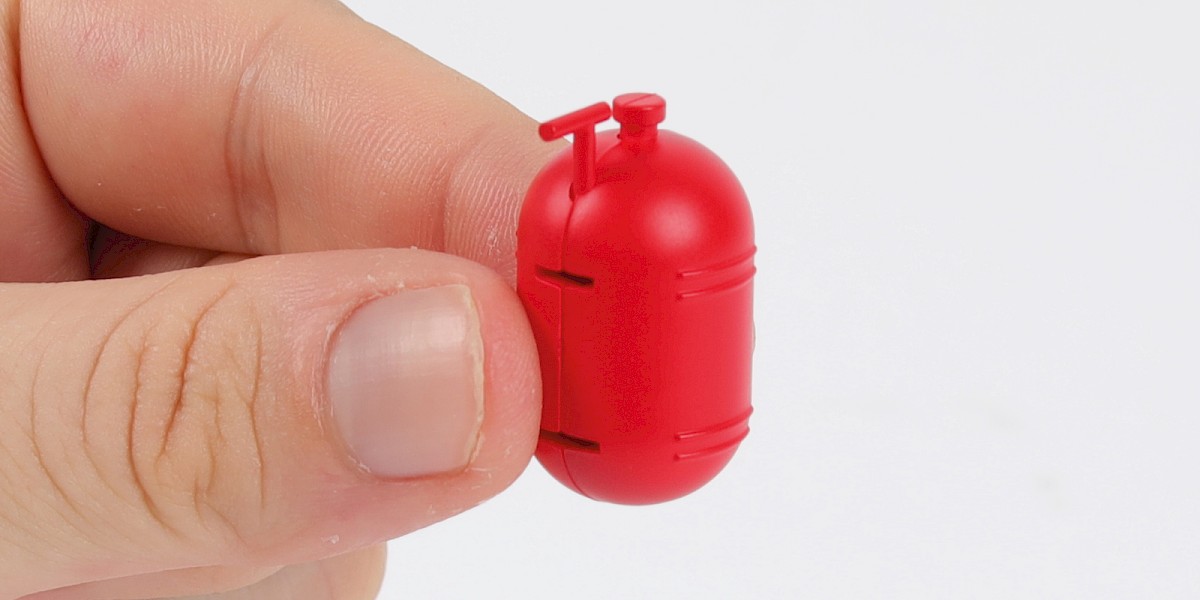
Step 1
Fit 95-F to 95-A.
Step 2
Fit the other 95-F to the assembly.
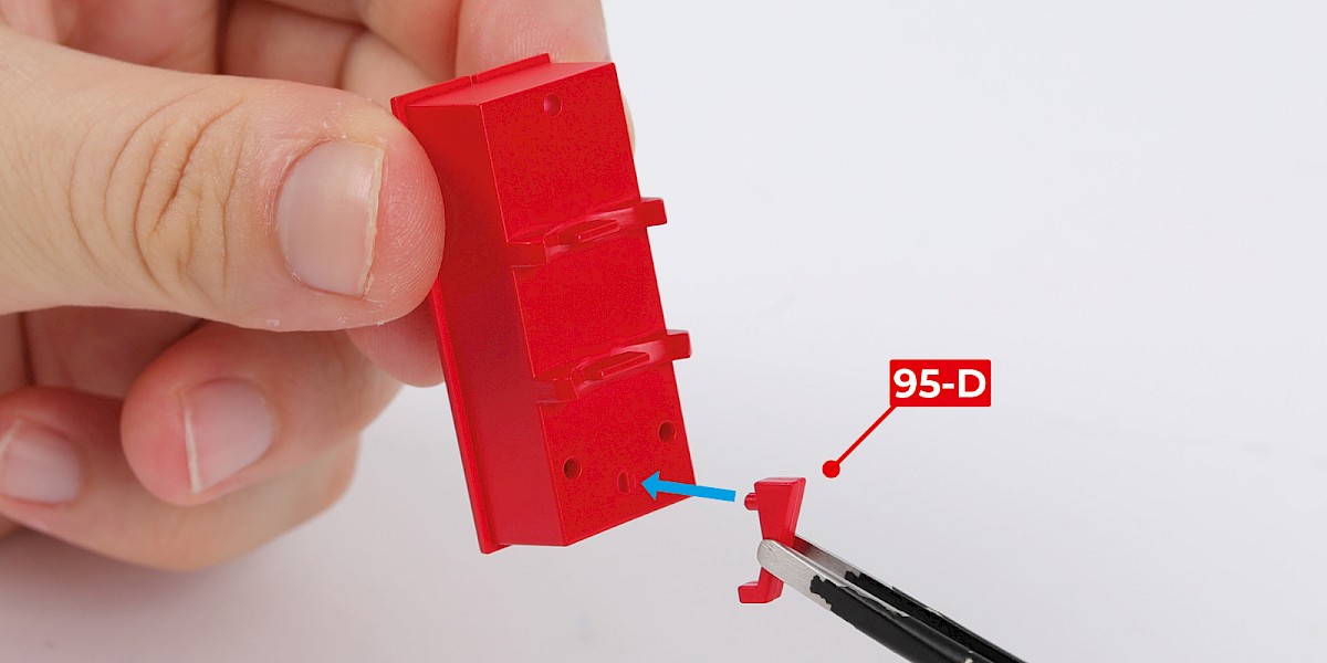
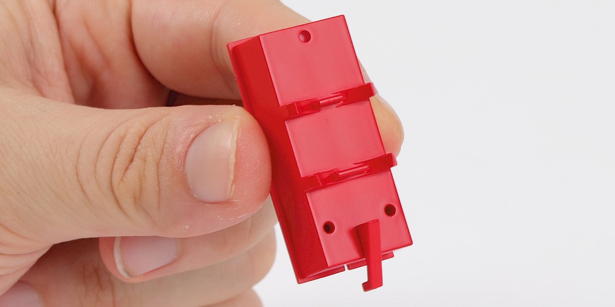
Step 3
Fit 95-D to the assembly.
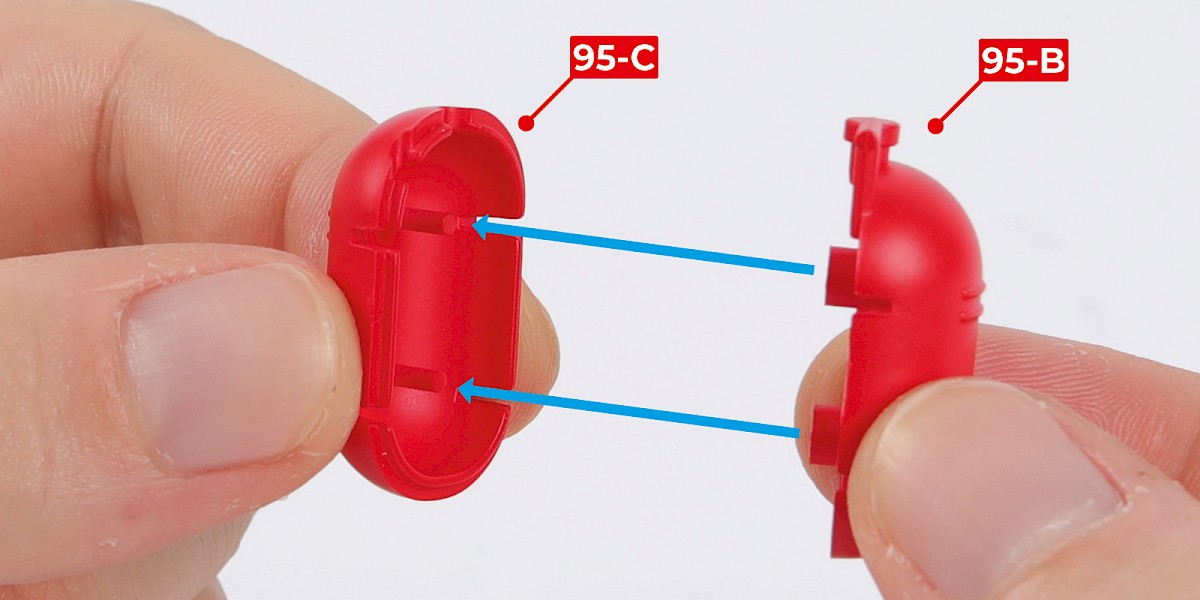
Step 4
Fit 95-B to 95-C.
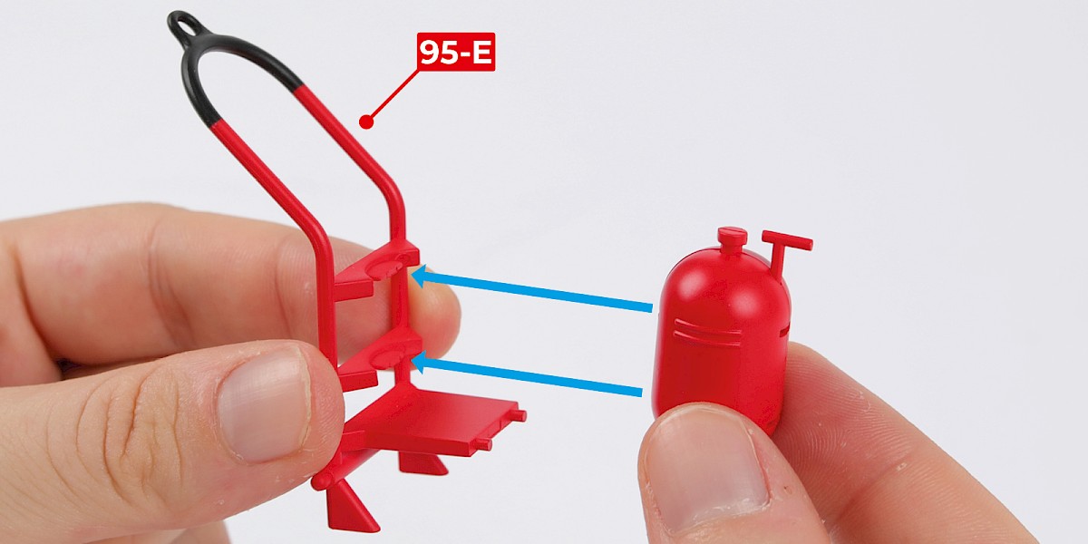
Step 5
Fit the assembly to 95-E.
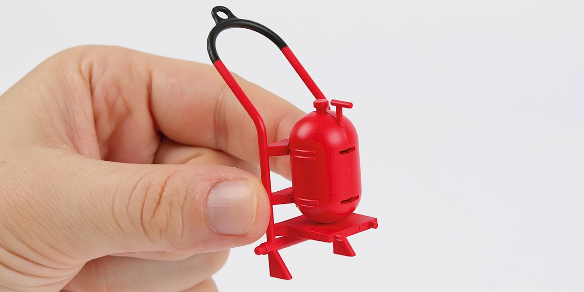
Step 6
Fit the two assemblies together.
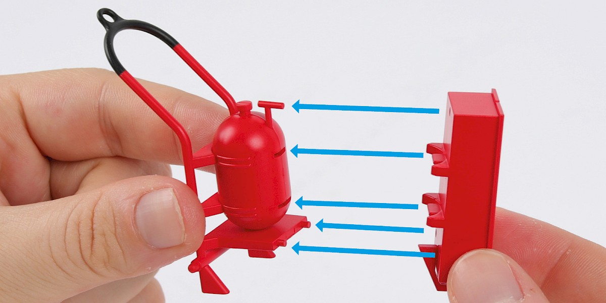
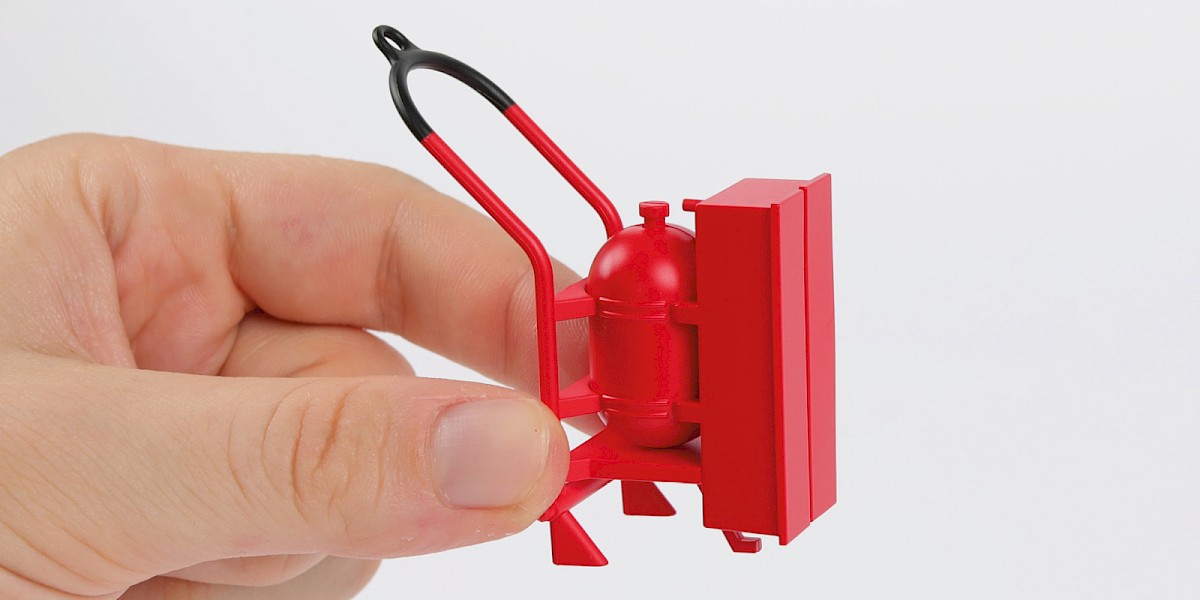
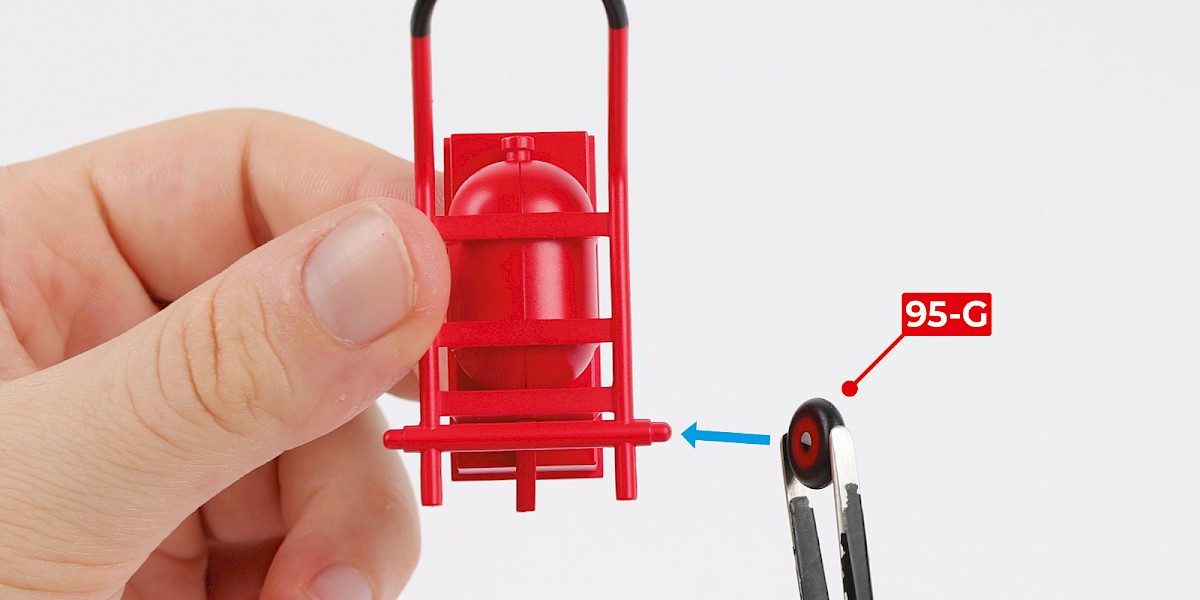
Step 7
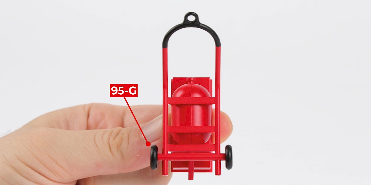
Fit 95-G to the assembly.
Fit another 95-G to the assembly.
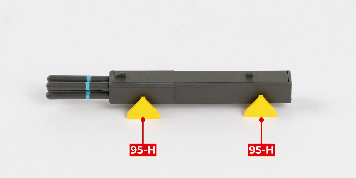
Step 8
The racks 95-H can be used to display a DAGR missile launcher (stage 80).
STAGE COMPLETE
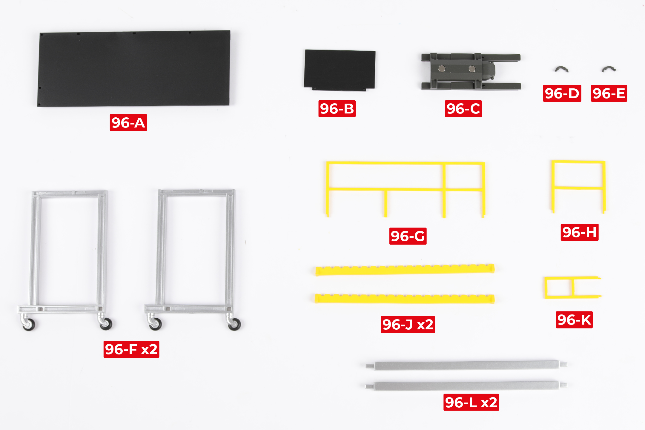
PARTS LIST
| 96-A | 96-G |
| 96-B | 96-H |
| 96-C | 96-J x2 |
| 96-D | 96-K |
| 96-E | 96-L x2 |
| 96-F x2 |
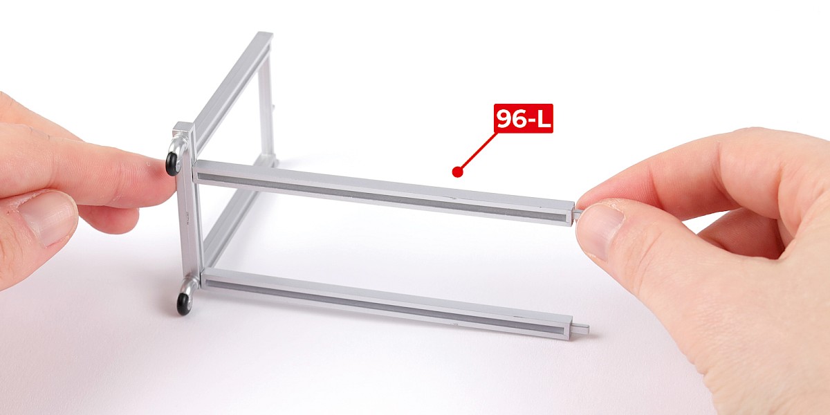
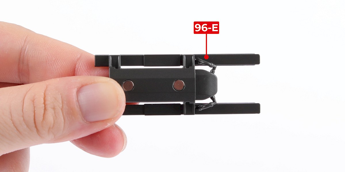
Step 1
Glue 96-L to 96-F. Do not allow the glue to dry, you may need to adjust the parts.
Glue another 96-L to the assembly.

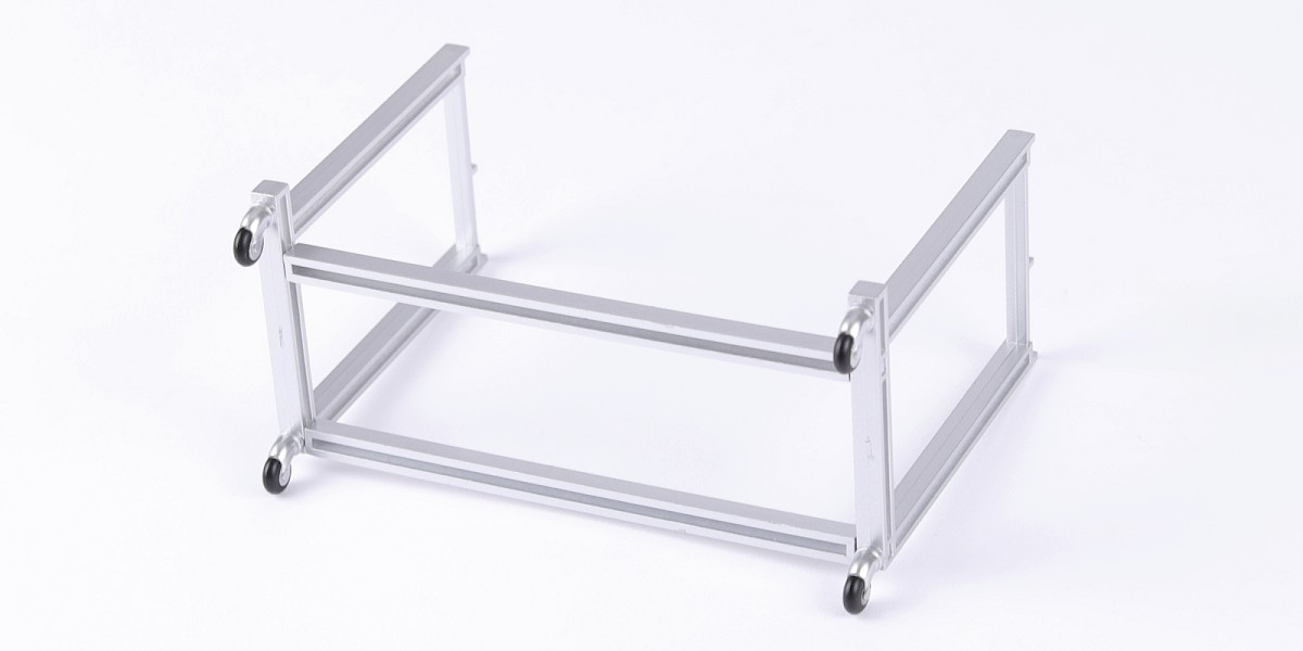
Step 2
Glue 96-F to the assembly.

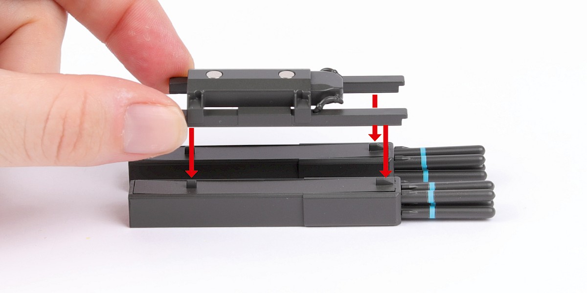
Step 3
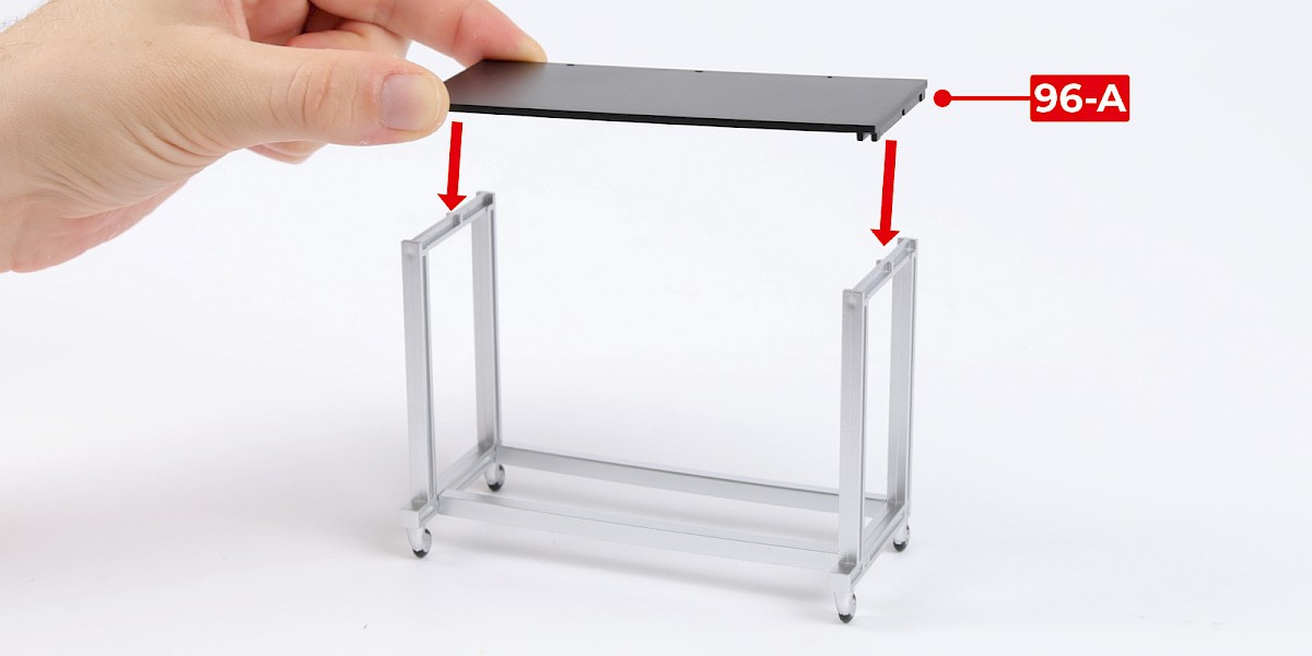
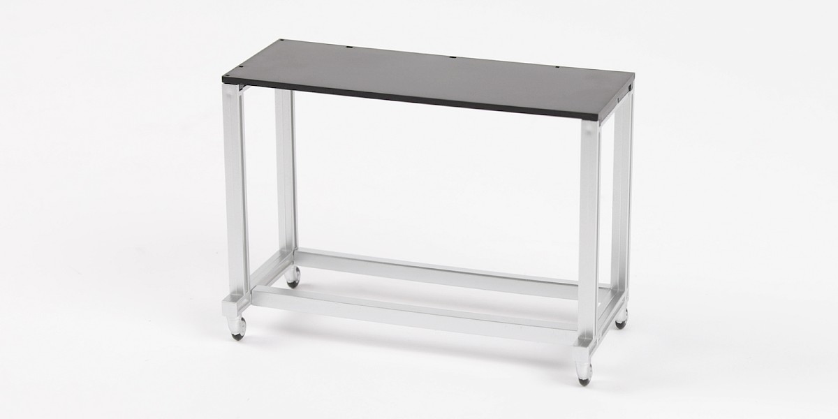
Glue 96-A to the assembly.
Step 4
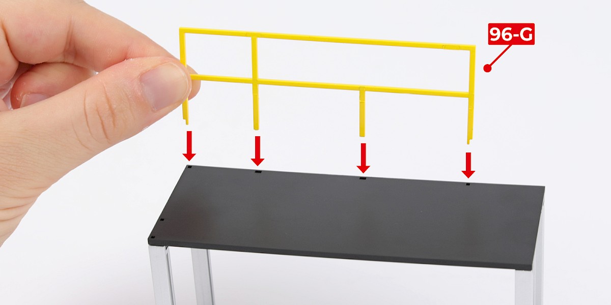
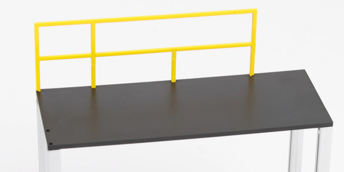
Glue 96-G to the assembly.
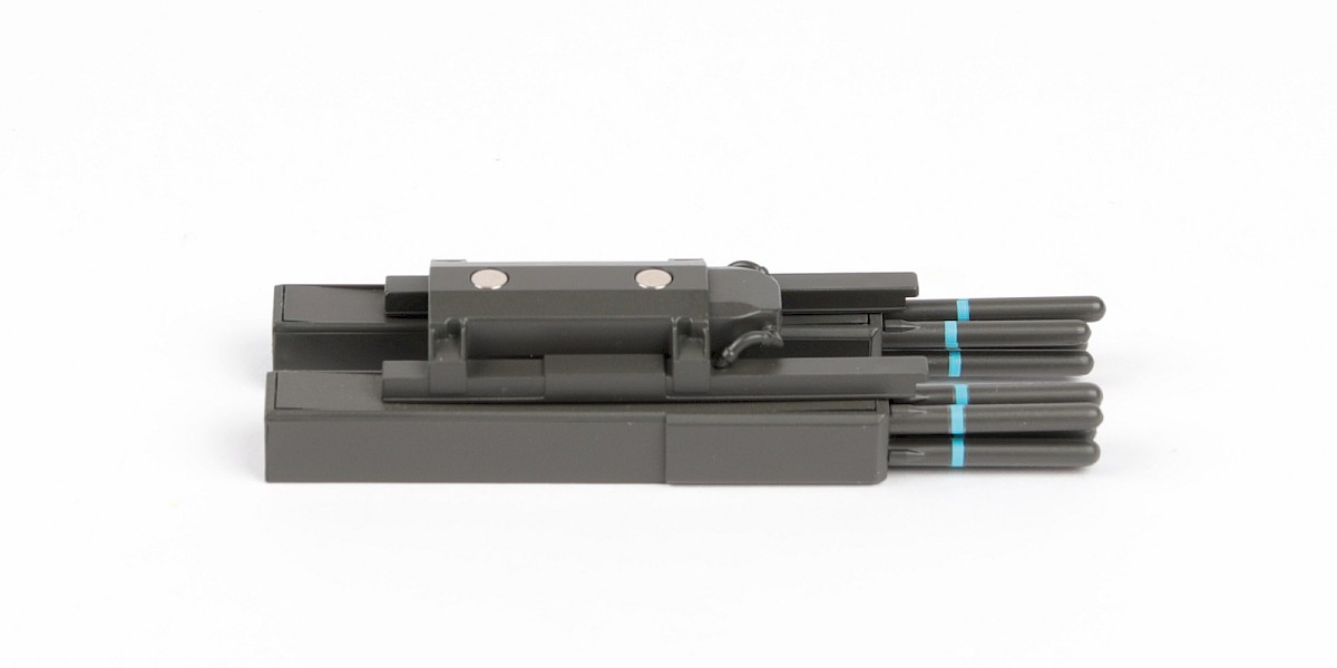
Step 5
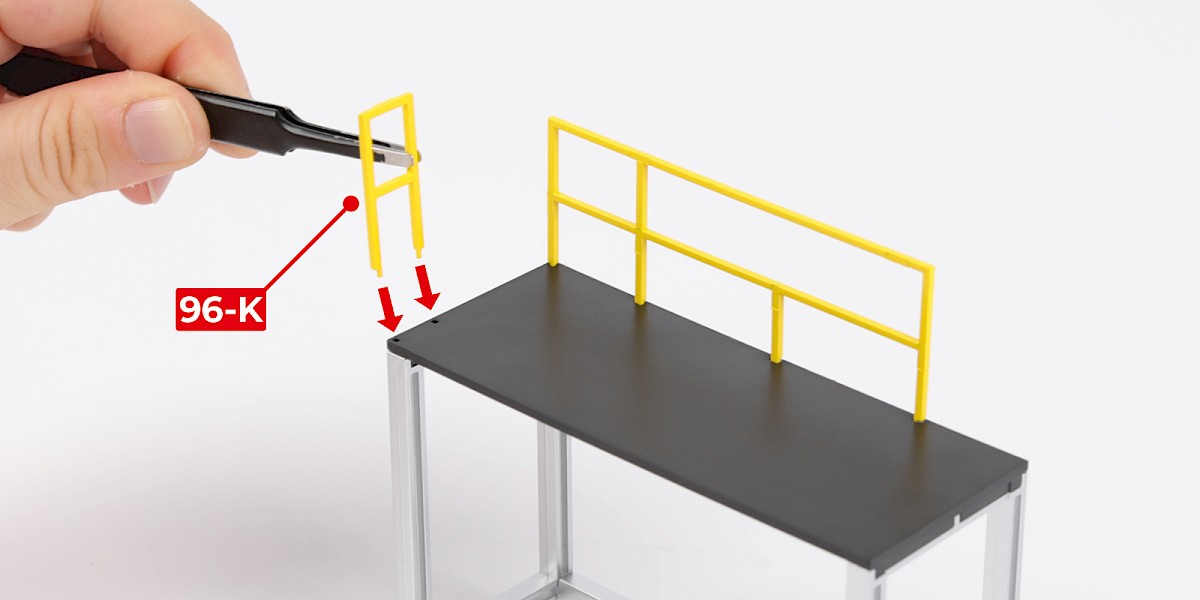
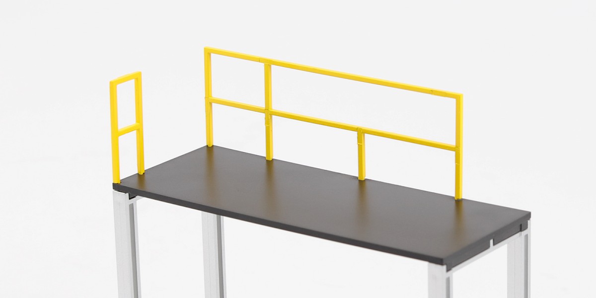
Glue 96-K to the assembly.
Step 6
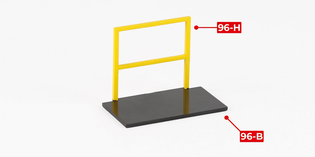
Glue 96-H to 96-B.
Step 7
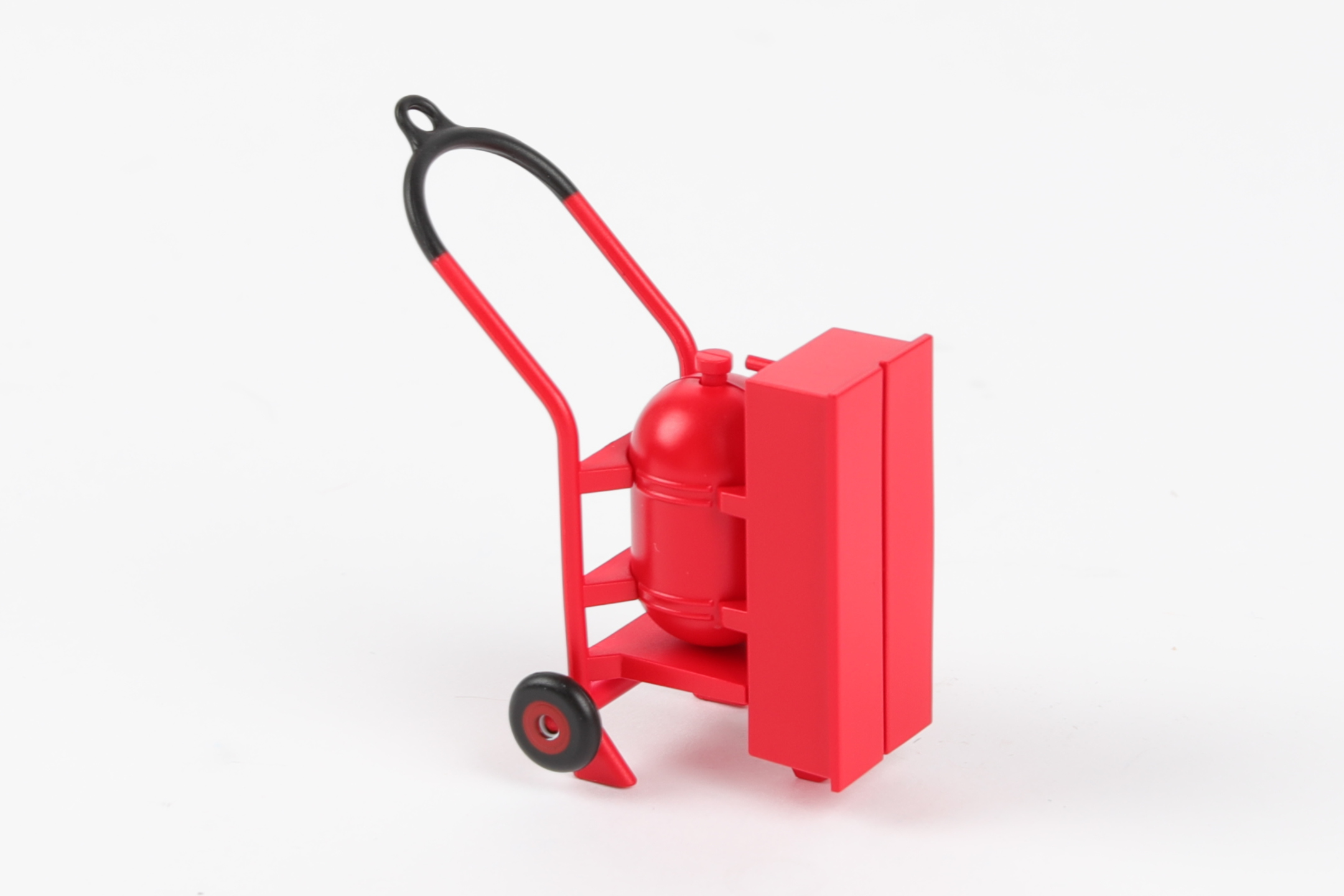
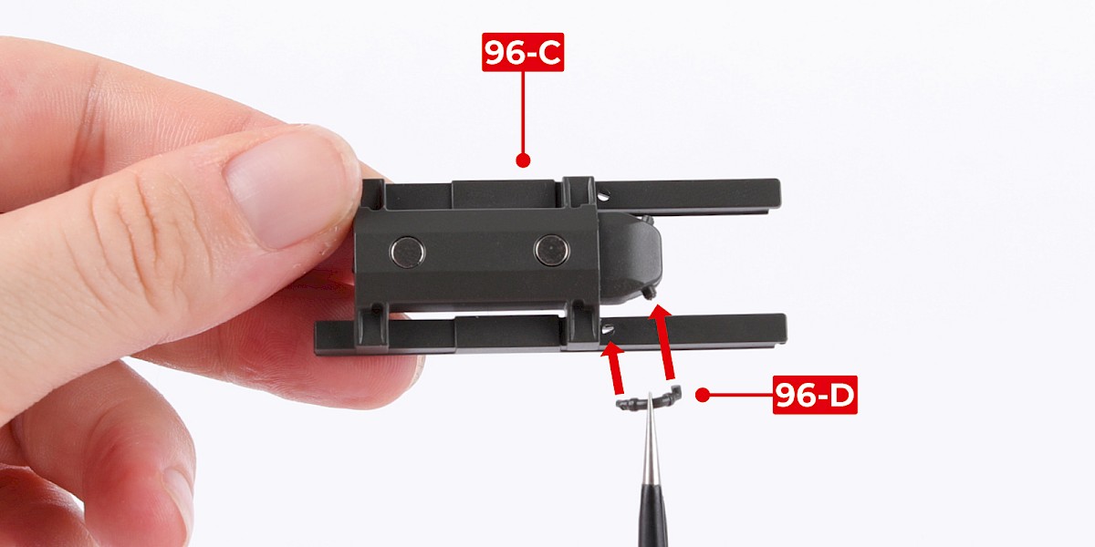
You will now assemble an M299 launcher with DAGR missiles.
Fit 96-D to 96-C.
Fit 96-E to 96-C
Step 8
Fit the assembly to two DAGR missile launchers (stage 30 and 80).
Step 9
Take decal sheet 93-L.
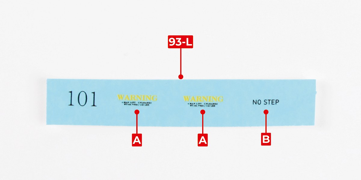
Step 10
Apply decals A to the assembly.
Step 11
Apply decal B to the assembly.
STAGE COMPLETE
PARTS LIST
| 97-A |
Step 1
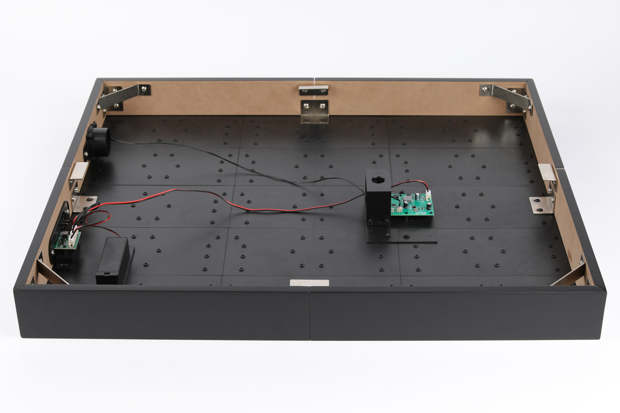
Take the display base (stage 96) and remove the battery compartment cover.
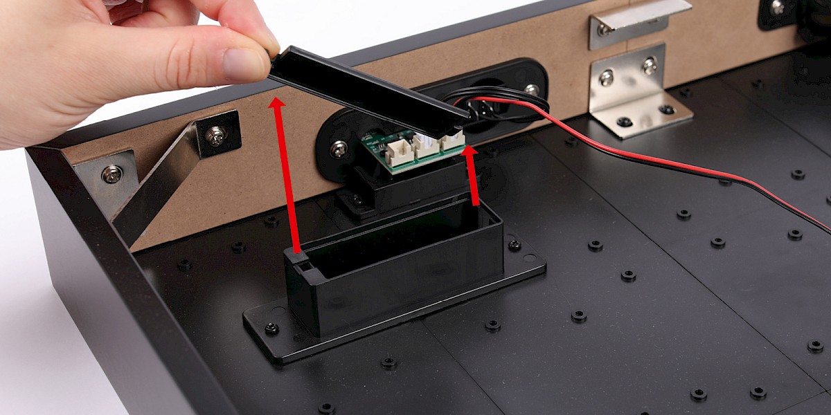
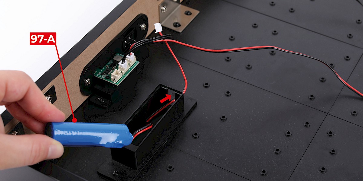
Step 2
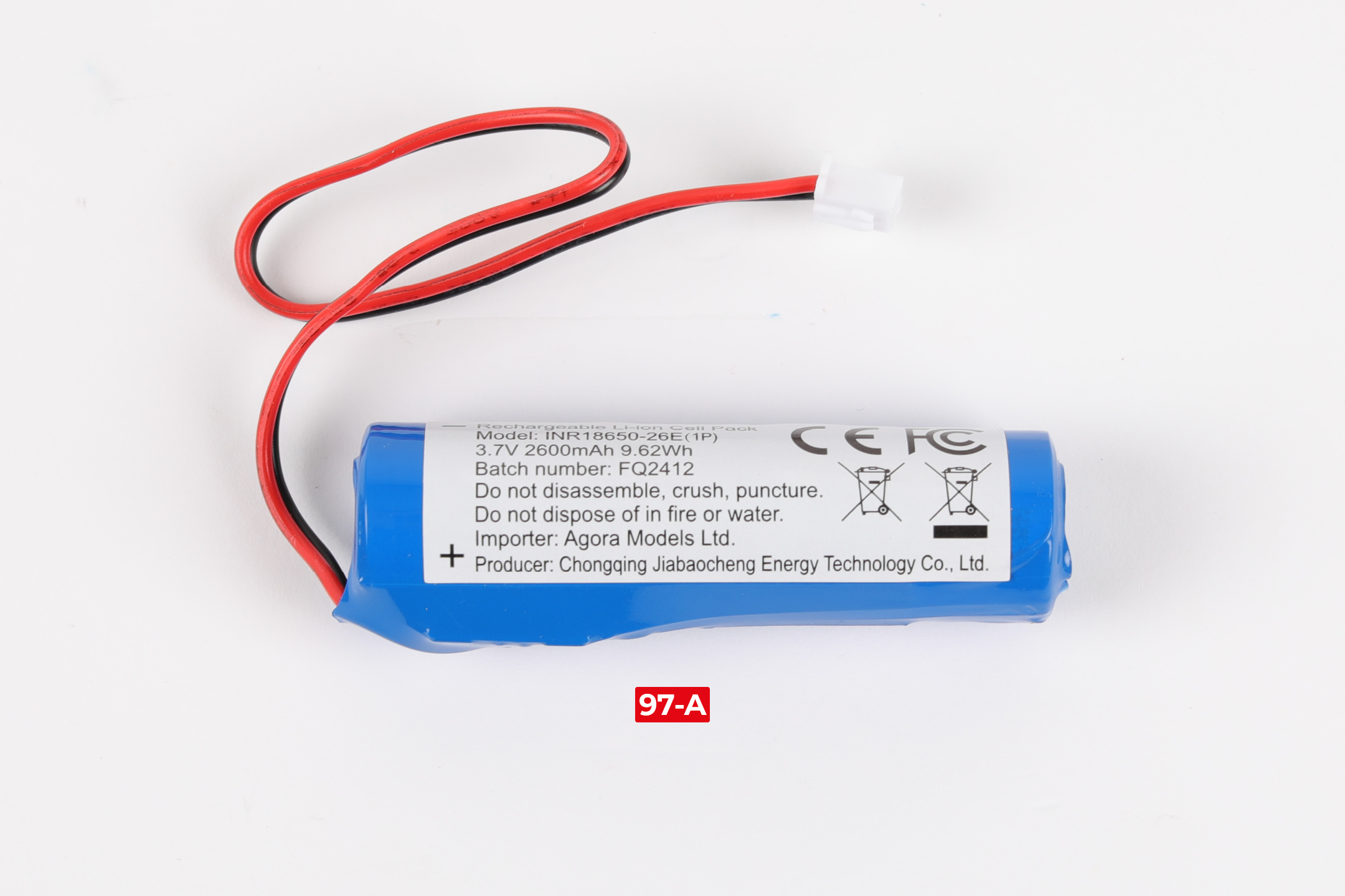
Thread the cable of 97-A through the opening then fit the battery in the battery compartment.
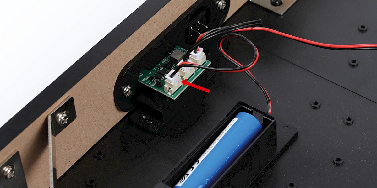
Plug the cable into the corresponding socket.
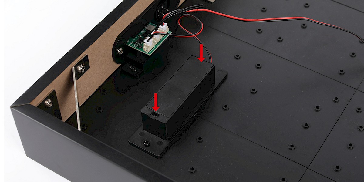
Step 3
Fit the battery compartment cover.
STAGE COMPLETE
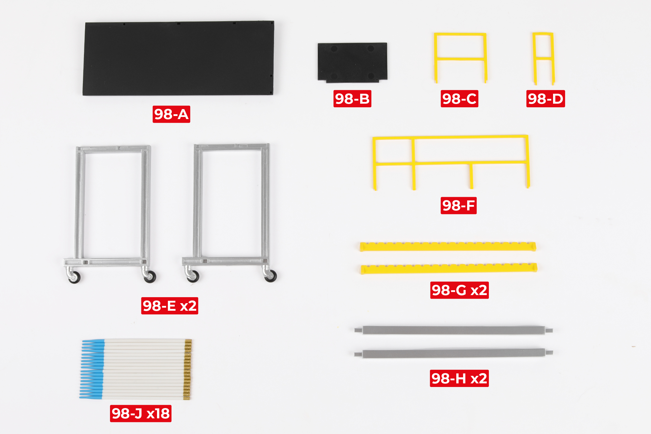
PARTS LIST
| 98-A | 98-F |
| 98-B | 98-G x2 |
| 98-C | 98-H x2 |
| 98-D | 98-J x18 |
| 98-E x2 |
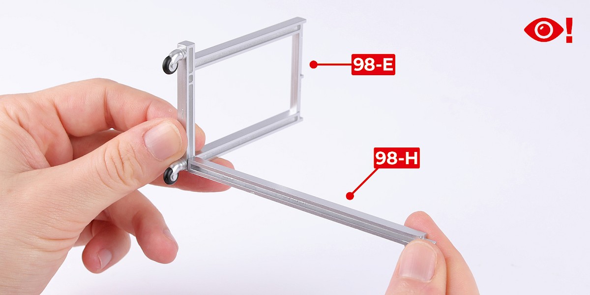
Step 1
Glue 98-H to 98-E. Do not allow the glue to dry, you may need to adjust the parts.
Glue another 98-H to the assembly.

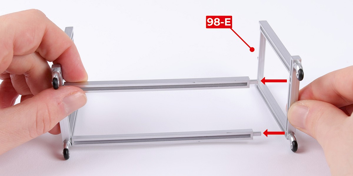
Step 2
Glue 98-E to the assembly.

Step 3
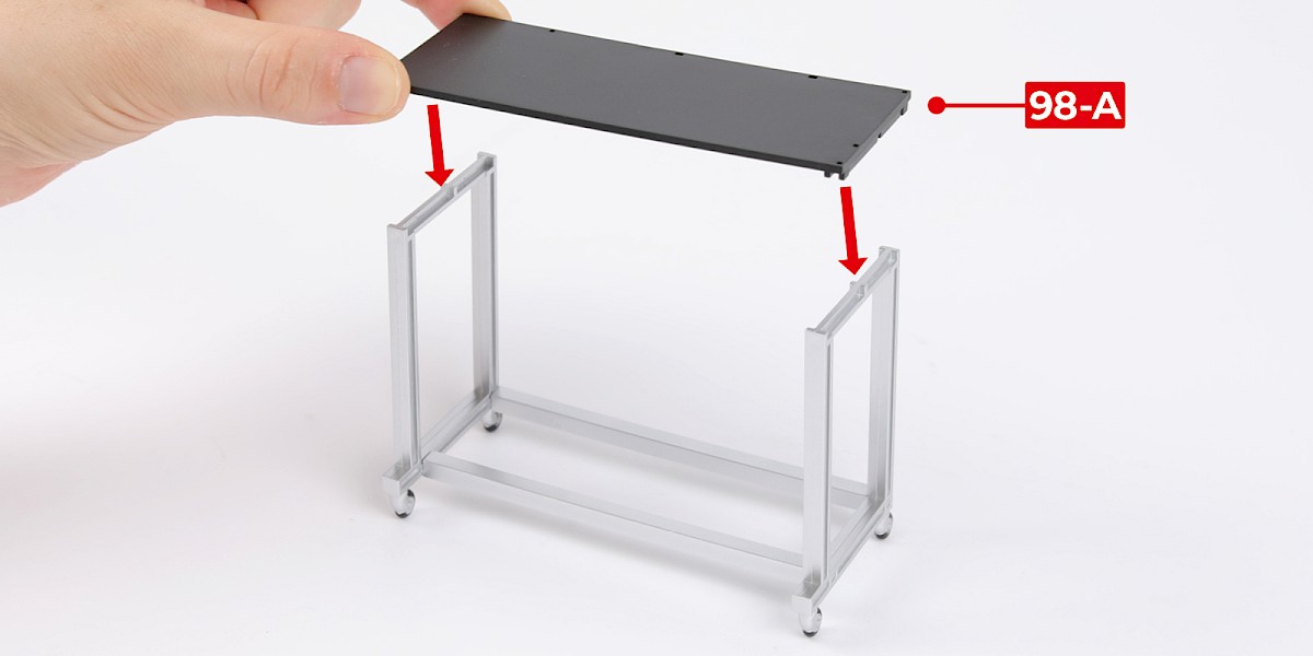
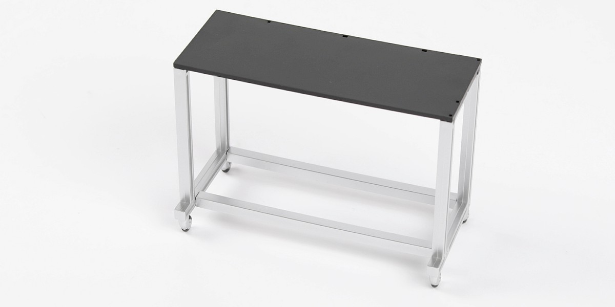
Glue 98-A to the assembly.
Step 4
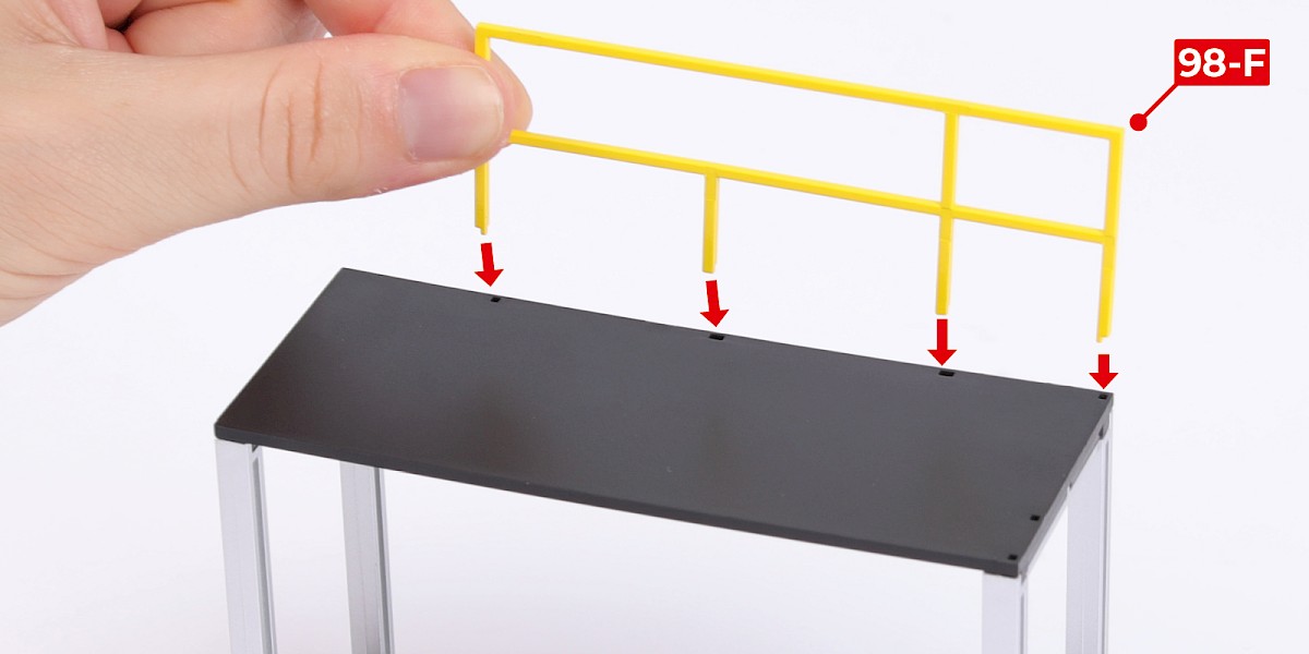
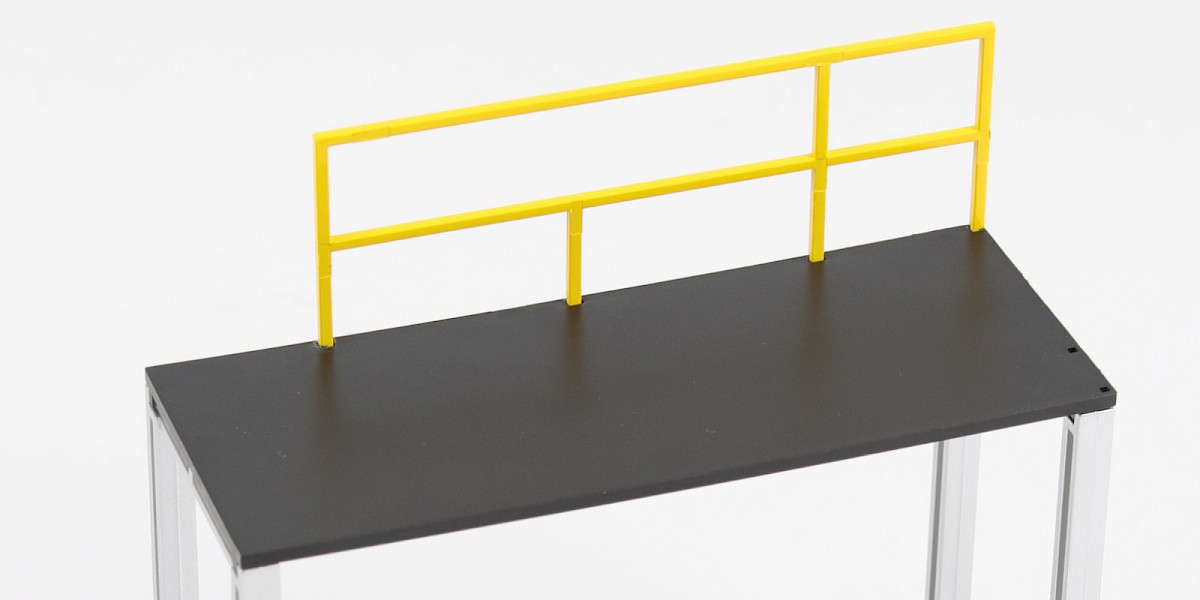
Glue 98-F to the assembly.
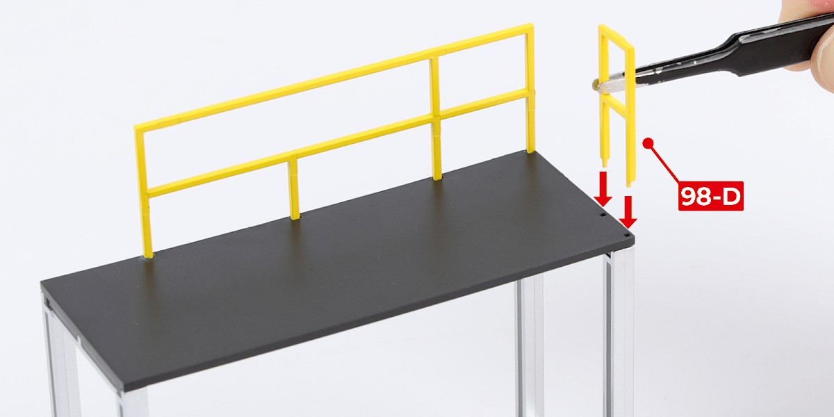
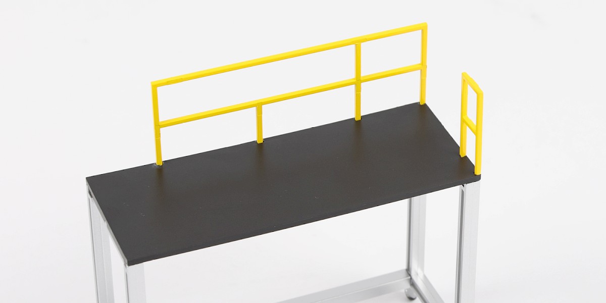
Step 5
Glue 98-D to the assembly.
Step 6
Glue 98-C to 98-B.

Step 7
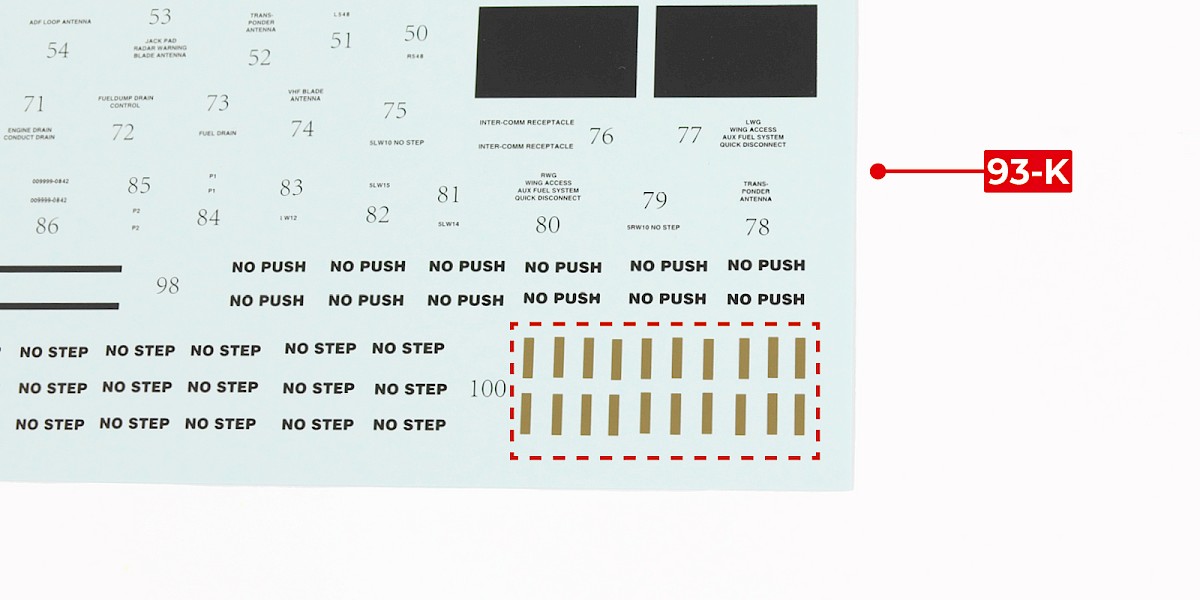
You will now add the decals to a set of rockets.
Cut the decals outlined in red from 93-K.
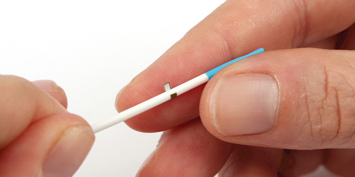
Step 8
Apply a decal to 98-J. Use the rockets from previous stages as a reference when positioning the decals.
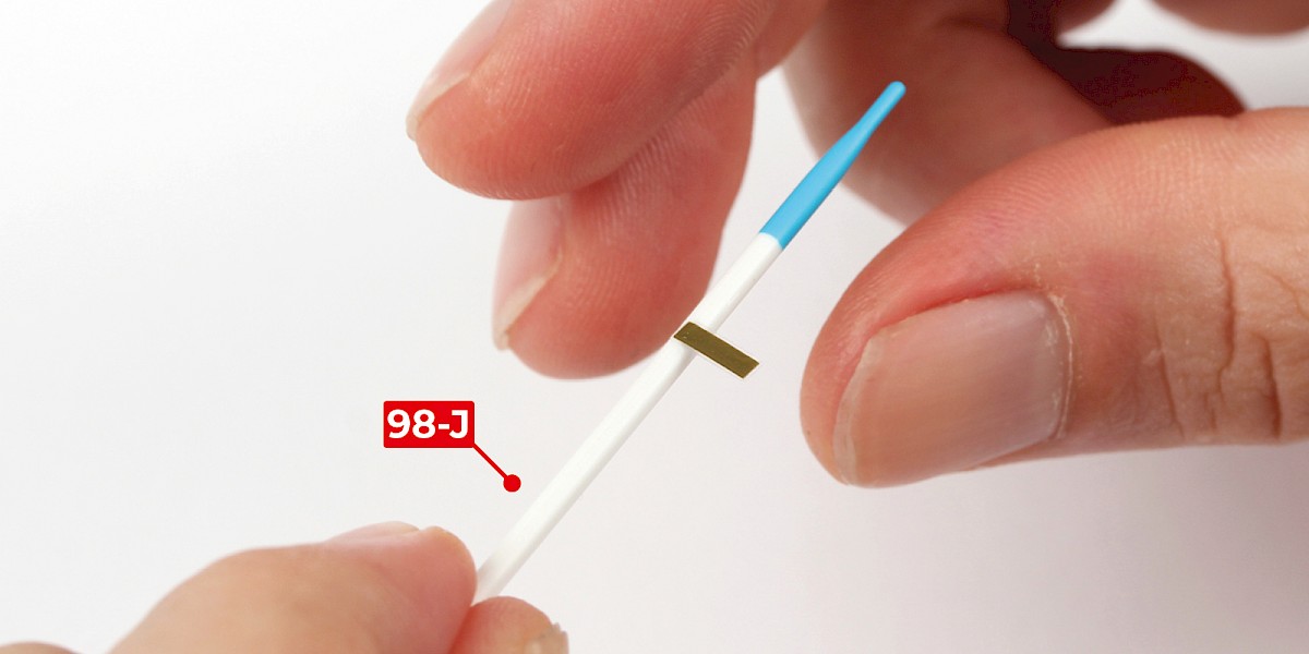
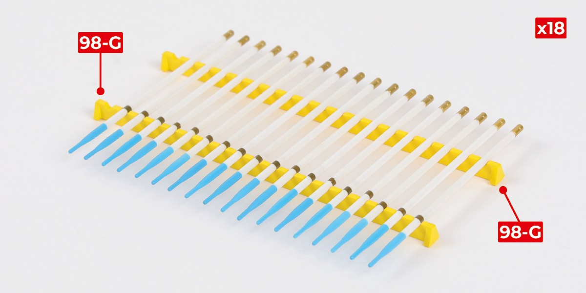
Step 9
Repeat to make 18 rockets.
The rockets can be displayed on the racks – parts 98-G.
STAGE COMPLETE
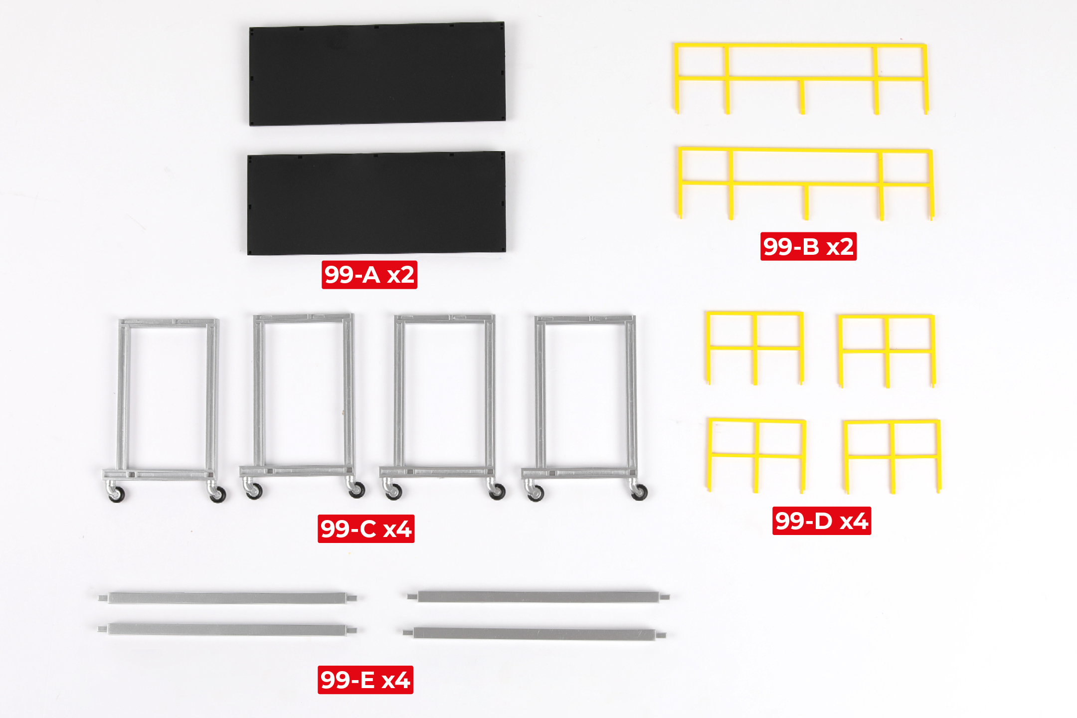
PARTS LIST
| 99-A x2 | 99-D x4 |
| 99-B x2 | 99-E x4 |
| 99-C x4 |
Step 1
Glue 99-E to 99-C. Do not allow the glue to dry, you may need to adjust the parts.
Glue another 99-E to the assembly.


Step 2
Glue 99-C to the assembly.


Step 3
Glue 99-A to the assembly.
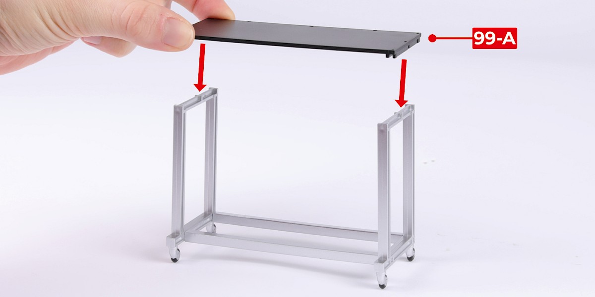
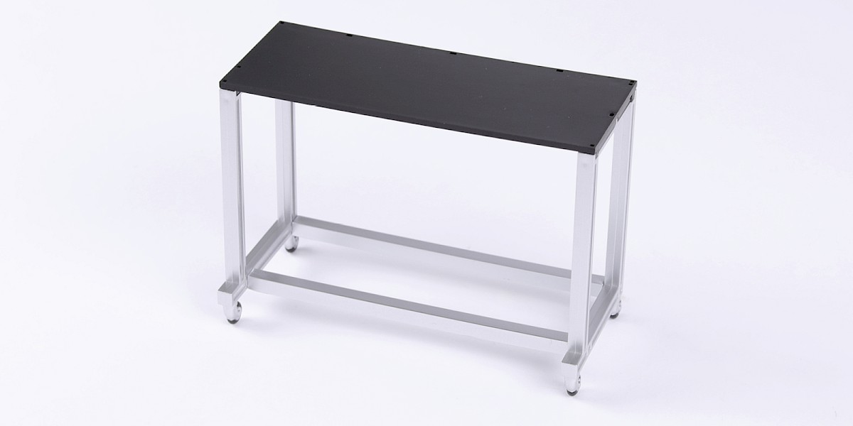
Step 4
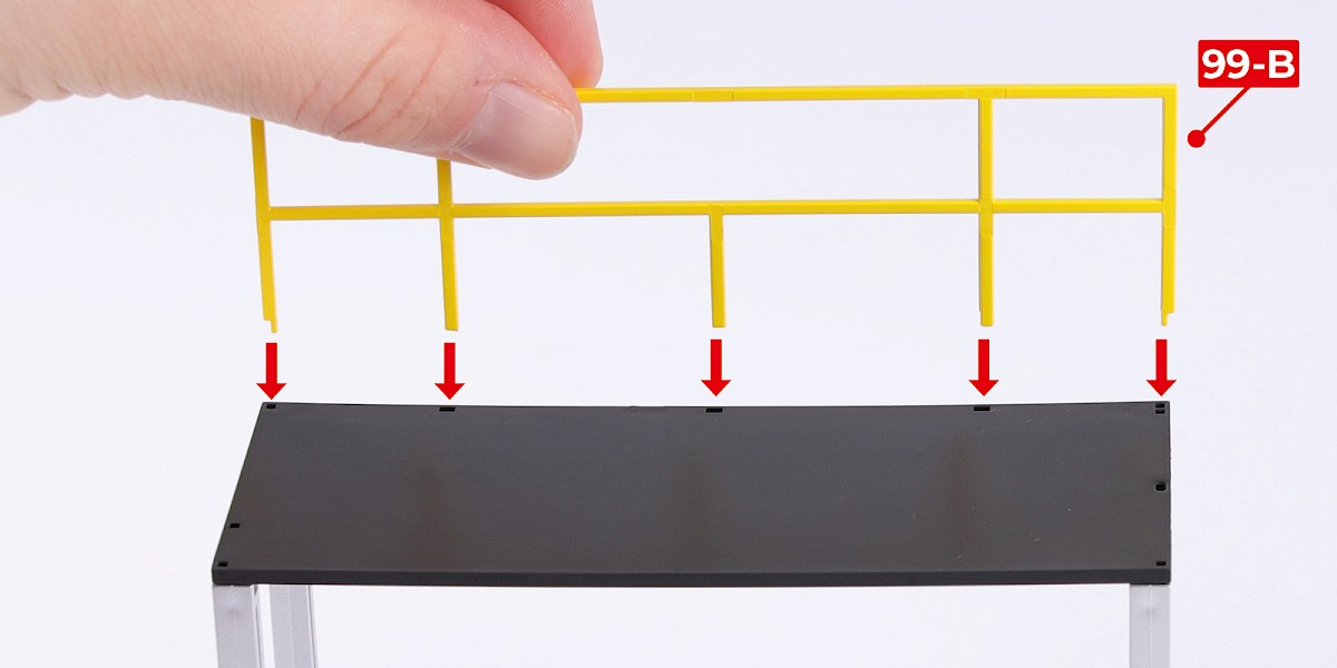
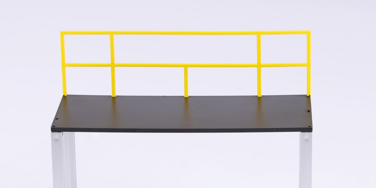
Glue 99-B to the assembly.
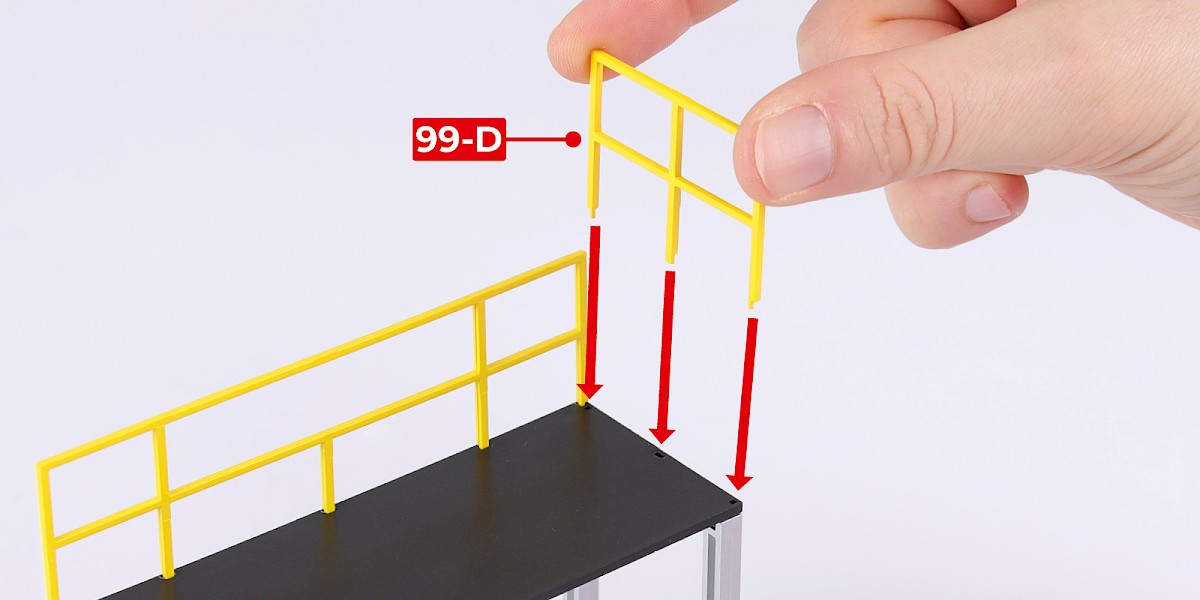
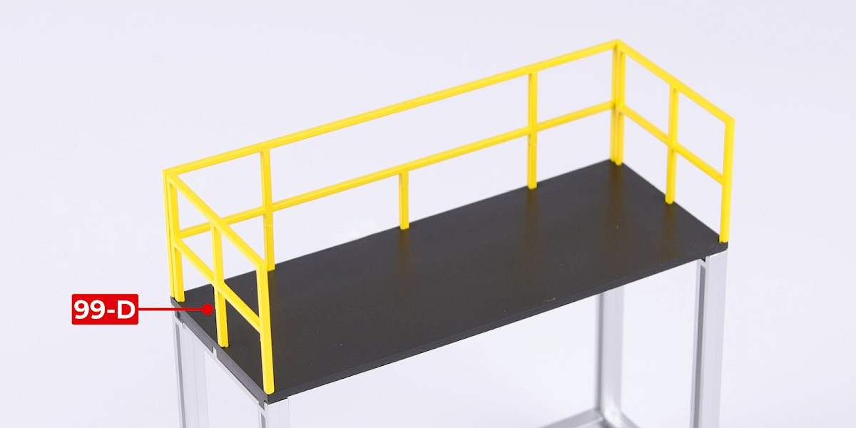
Step 5
Glue 99-D to each side of the assembly.
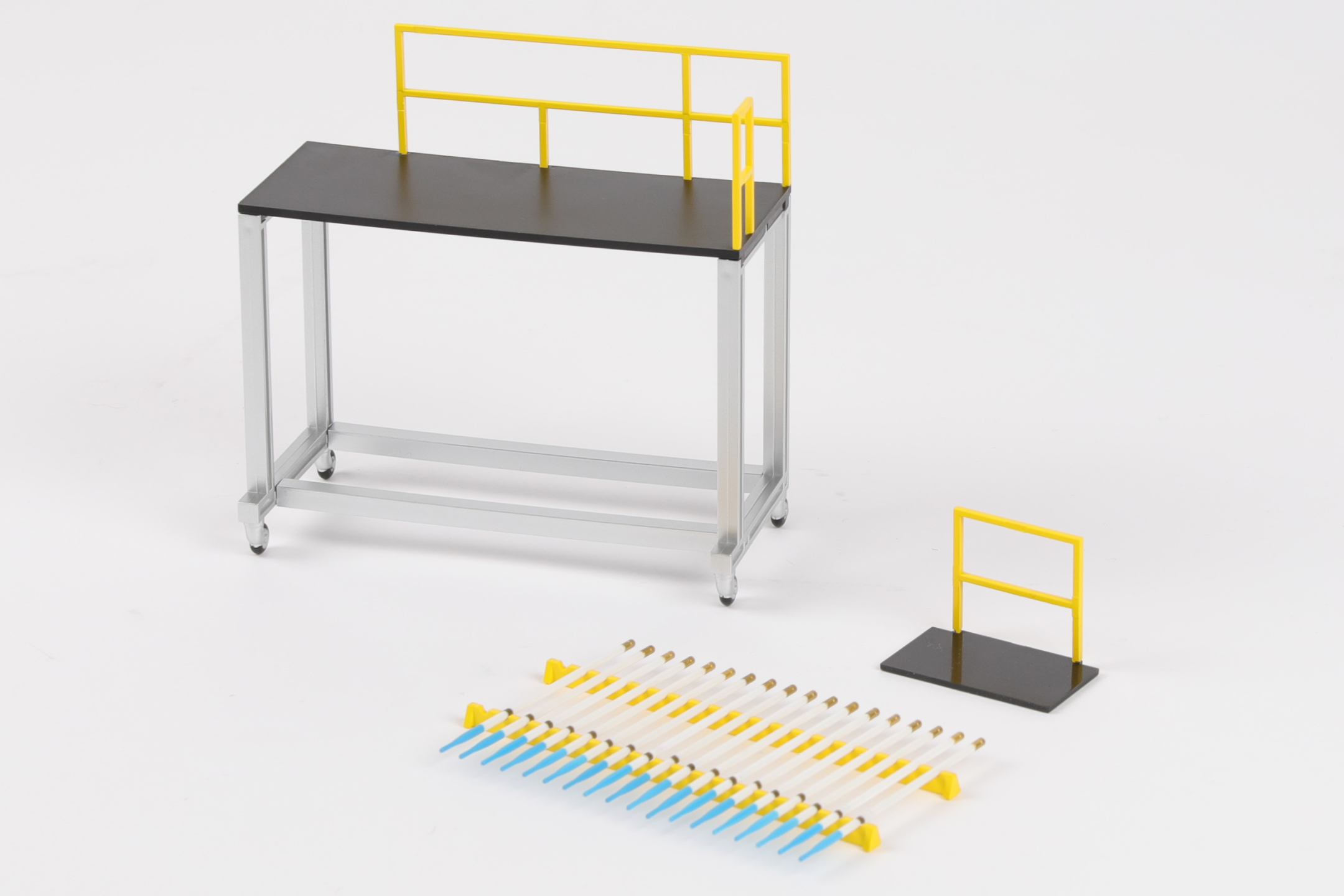
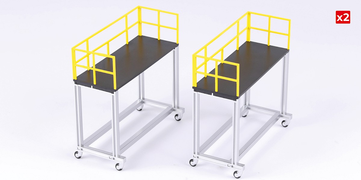
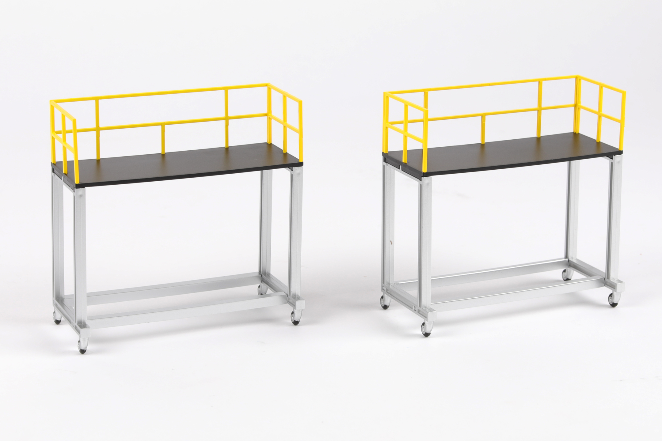
Step 6
Repeat steps 1–5 to assemble a second platform.
If you need to use the spare rail (part 83-F), glue it to the platform (stage 83).
STAGE COMPLETE
Before proceeding with this final stage, we recommend applying the decals you wish to use for finishing your model. Two of the sheets (93-K) in your pack look identical, check you are using the sheet with the smaller NO PUSH (#98) and NO STEP (#99) decals. The remainder can be used for spares. Instructions for each set of decals can be found by clicking on the links below.
- United States Army
- British Army (Army Air Corps)
- Royal Netherlands Air Force
- Japan Ground Self-Defense Force (JGSDF)
Once your decals are complete, please return to the steps for Stage 100.
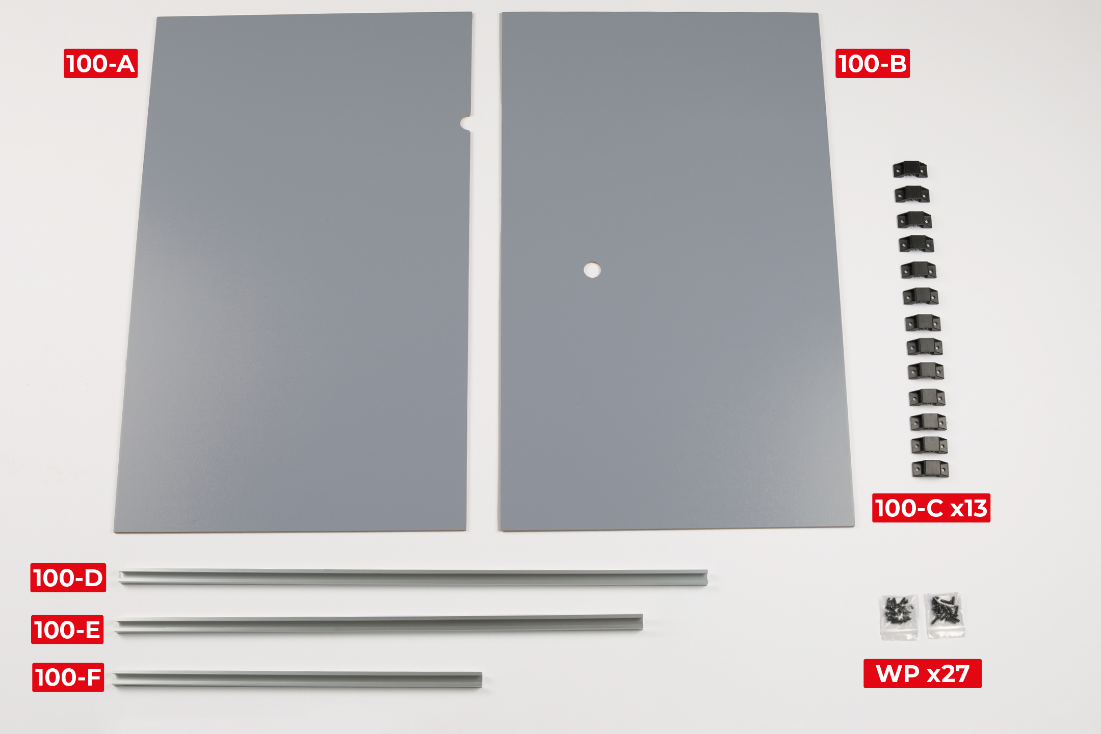
PARTS LIST
| 100-A | 100-E |
| 100-B | 100-F |
| 100-C x13 | WP x27 |
| 100-D |
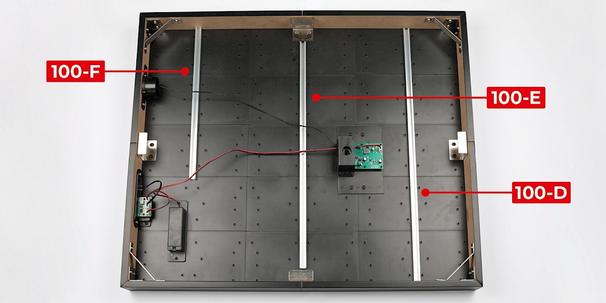
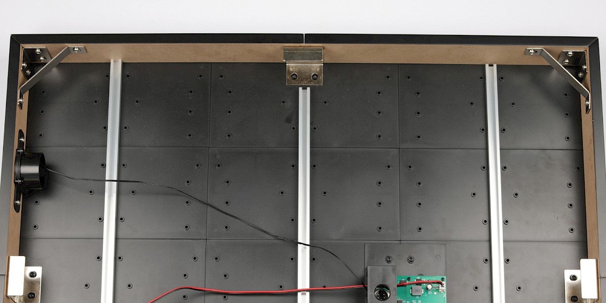
Step 1
Fit 100-D, 100-E and 100-F to the display base as shown.
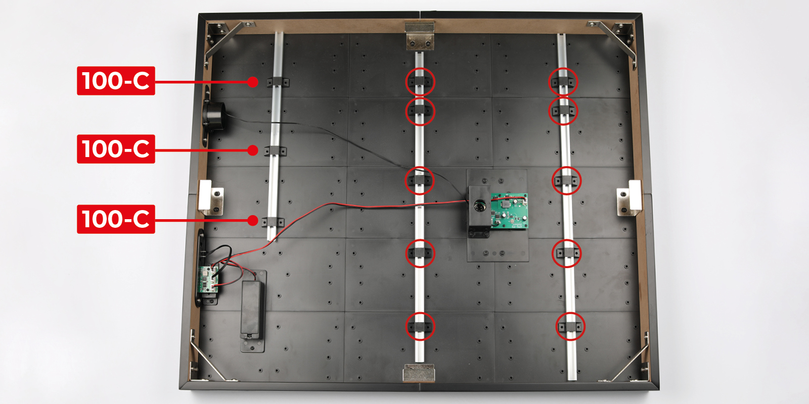
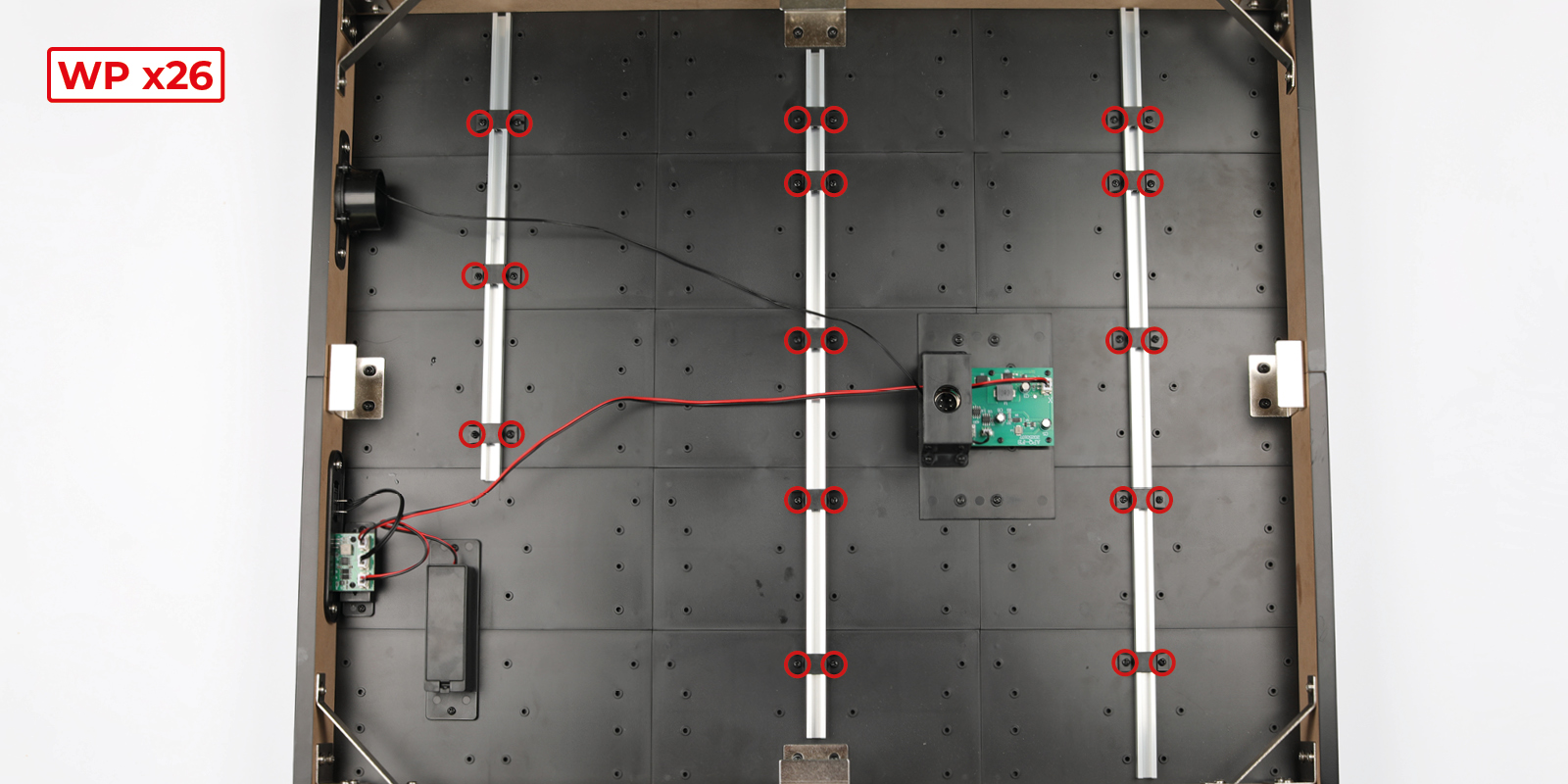
Step 2
Fit 100-C to the assembly at the positions indicated.
Secure with 26x WP.
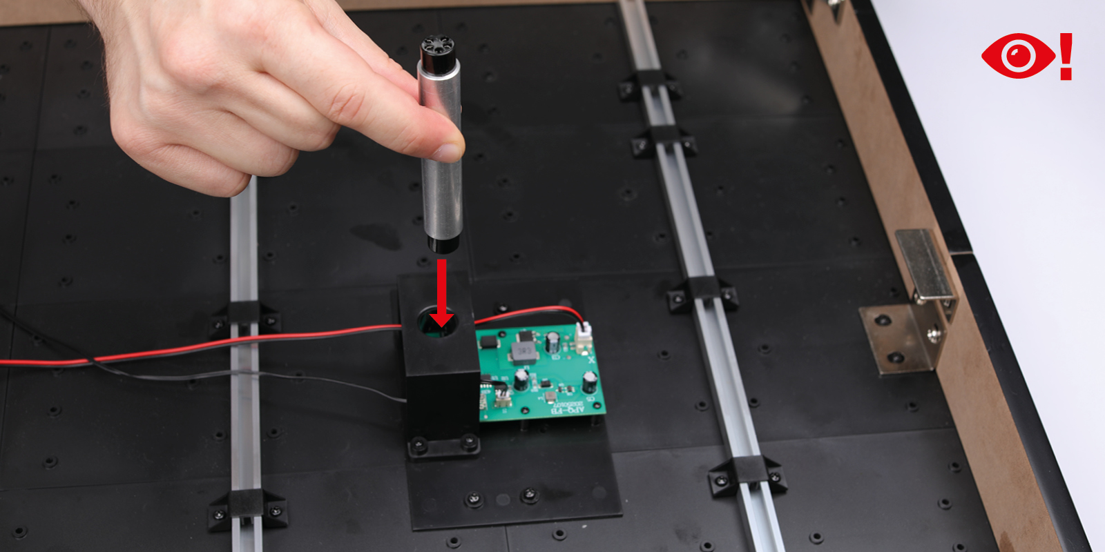
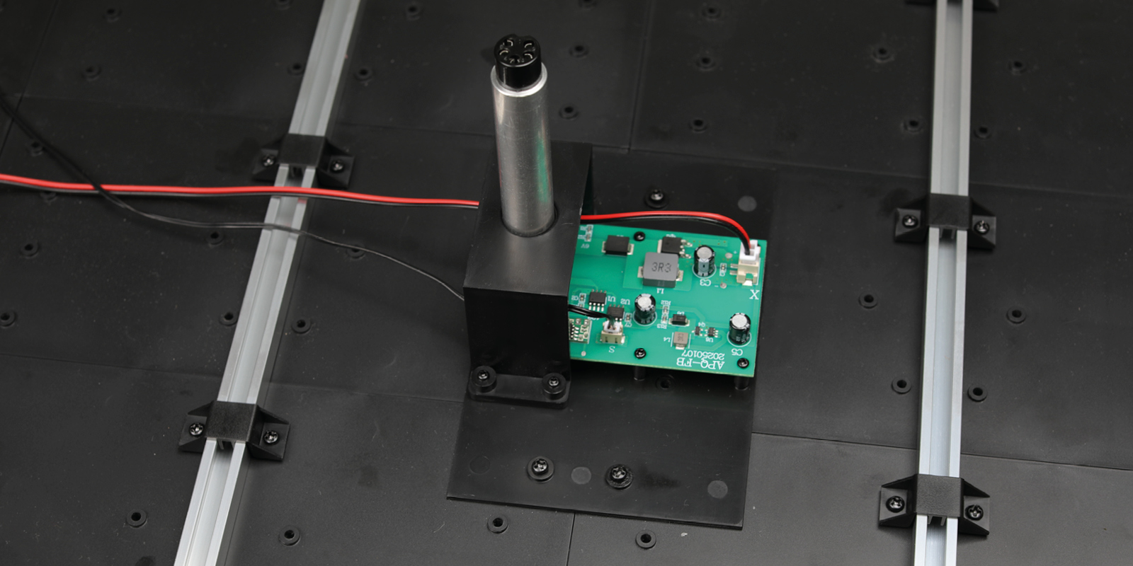
Step 3
Fit the support bar (stage 78) to the assembly.
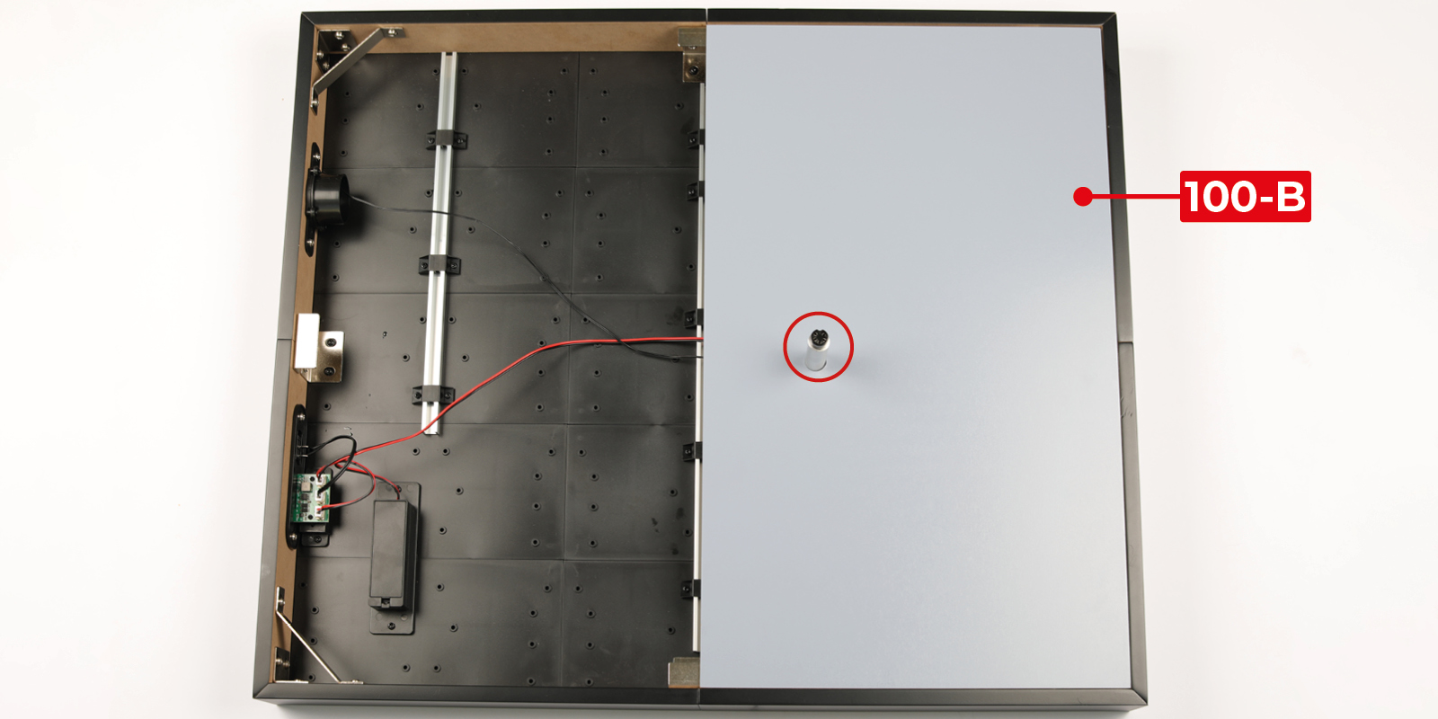
Step 4
Fit 100-B to the display base.
Fit 100-A to the display base.
Step 5
Fit the right HADS unit (stage 23) to the right engine nacelle.
Step 6
Fit the left HADS unit (stage 16) to the left engine nacelle.
Step 7
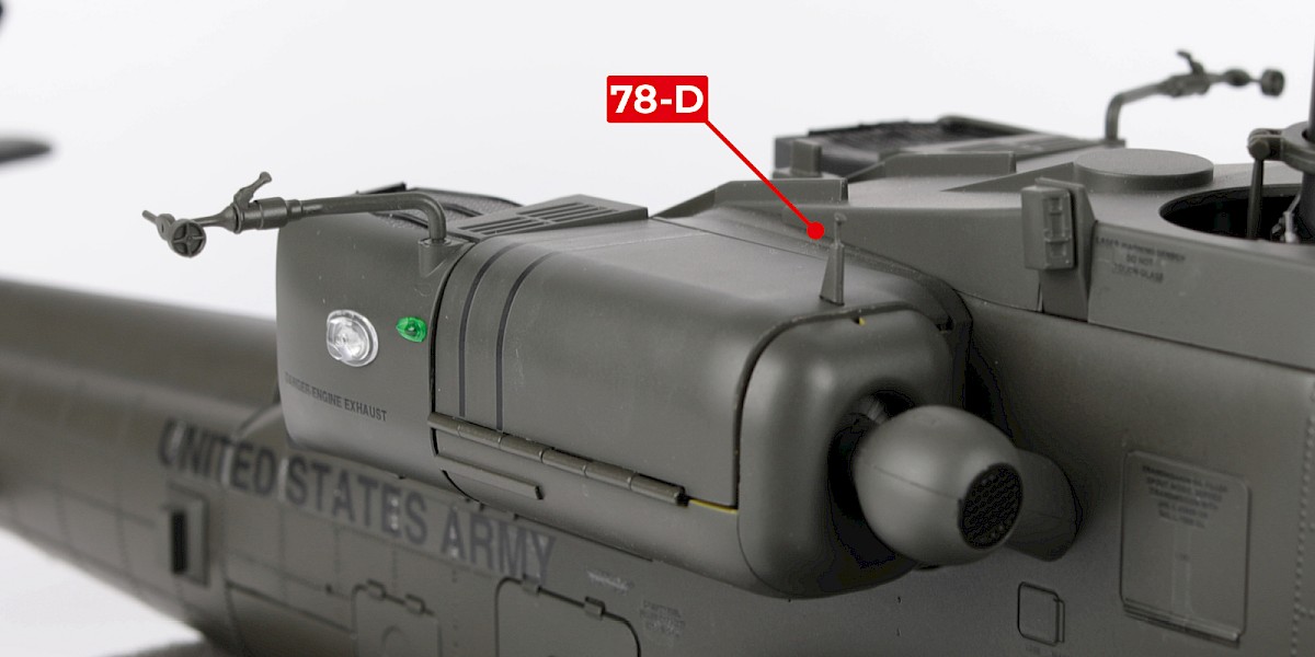
Fit 78-D (stage 78) to the left engine nacelle.
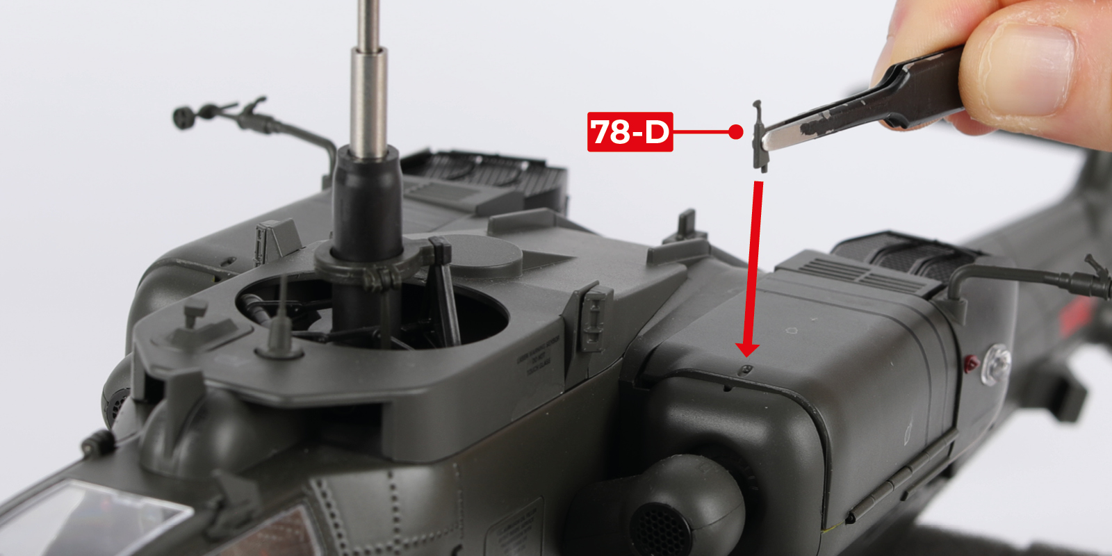
Step 8
Fit another 78-D to the right engine nacelle.
Step 9
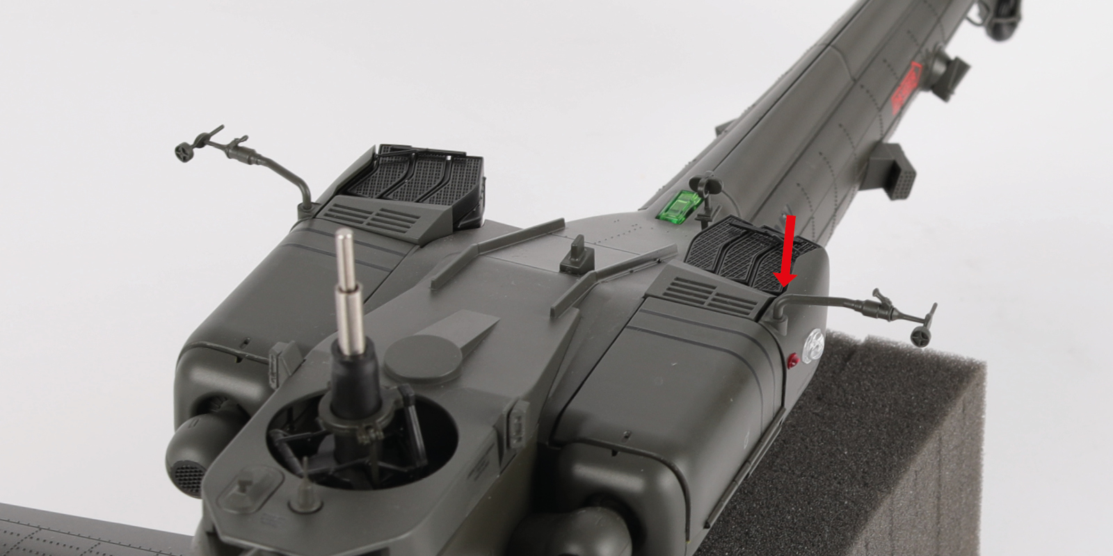
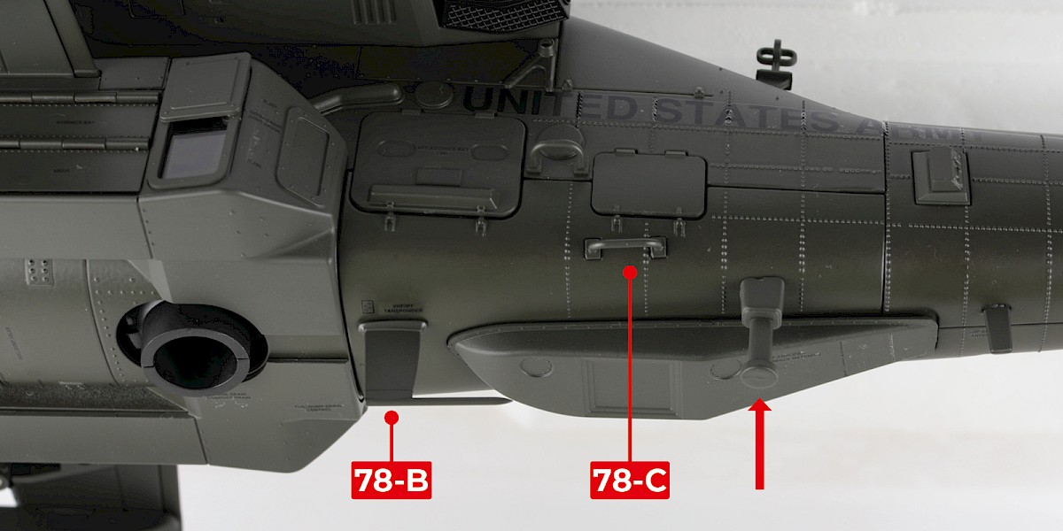
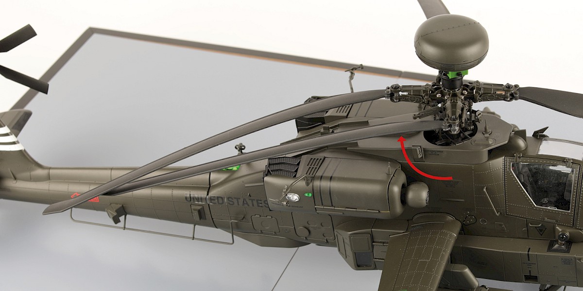
Fit 78-B and 78-C (stage 78) to the fuselage.
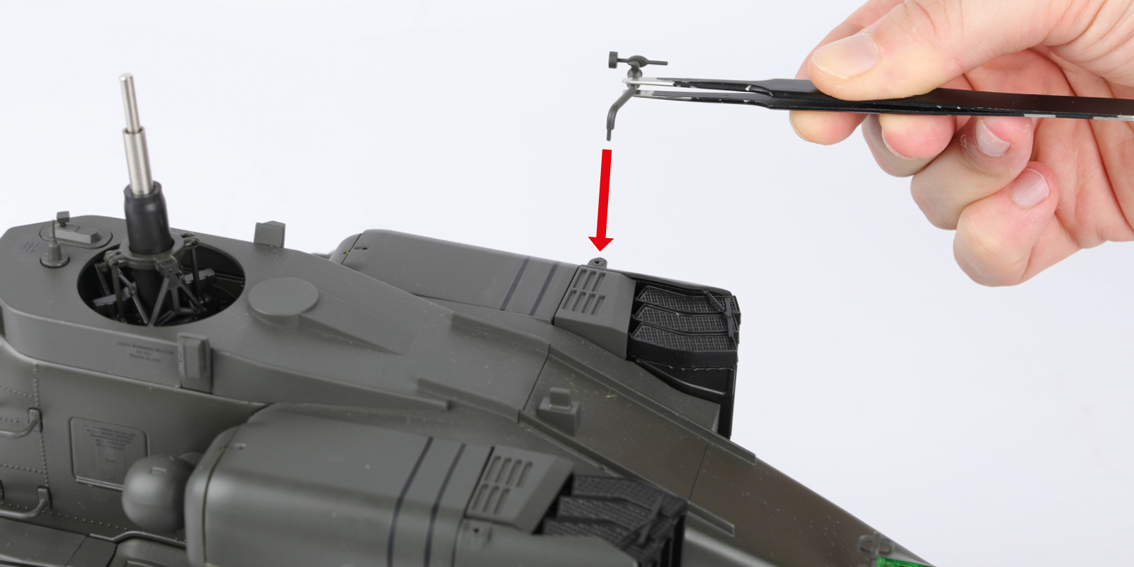
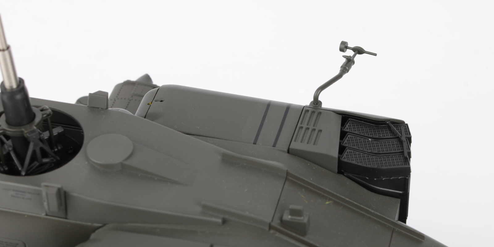
Fit the Bi-cone antenna (stage 60) to the fuselage (arrow).
Step 10
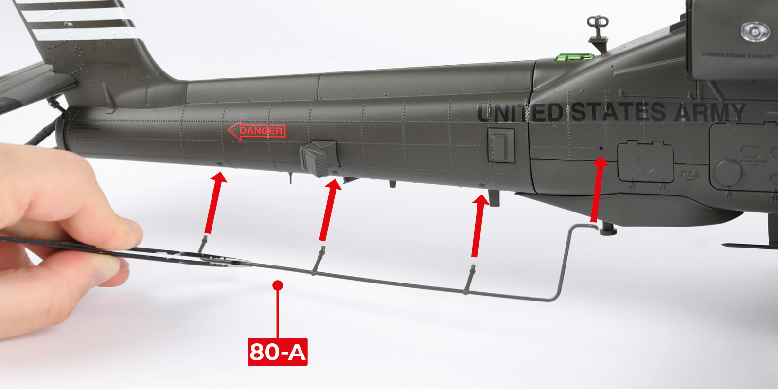
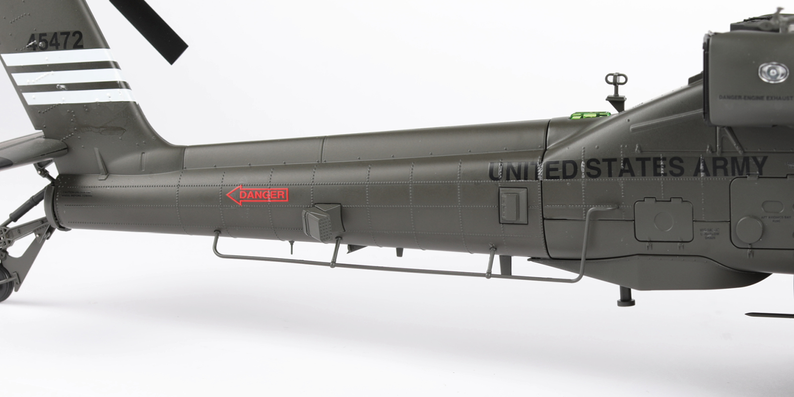
Fit 80-A to the assembly.
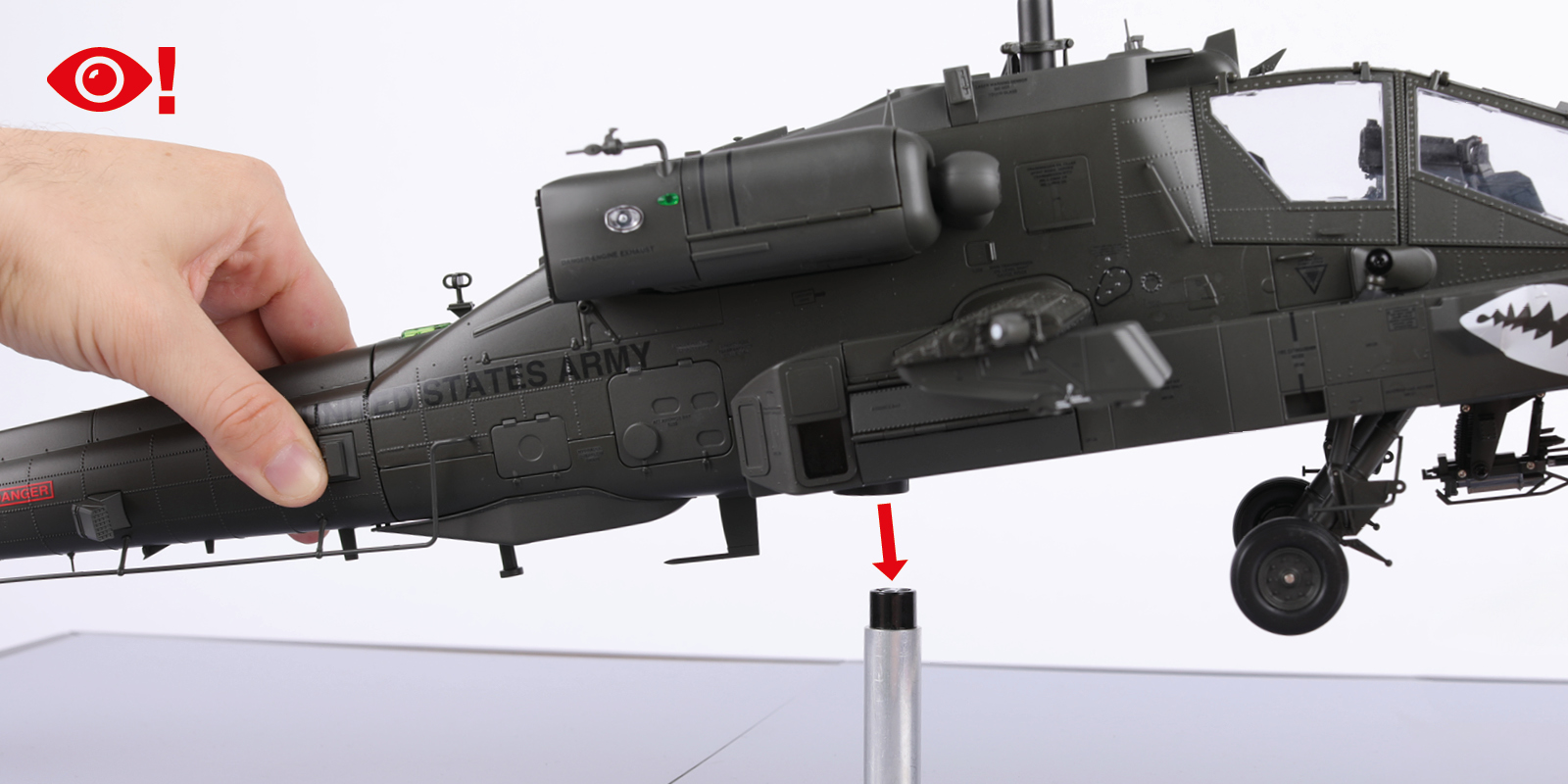
Step 11
Fit the assembly to the display base. Make sure the connector pins inside the model are in the correct orientation.
You may need to remove some excess paint from the interior of the power connector to get a good fit.
Step 12
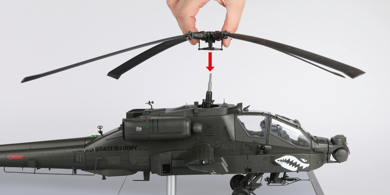
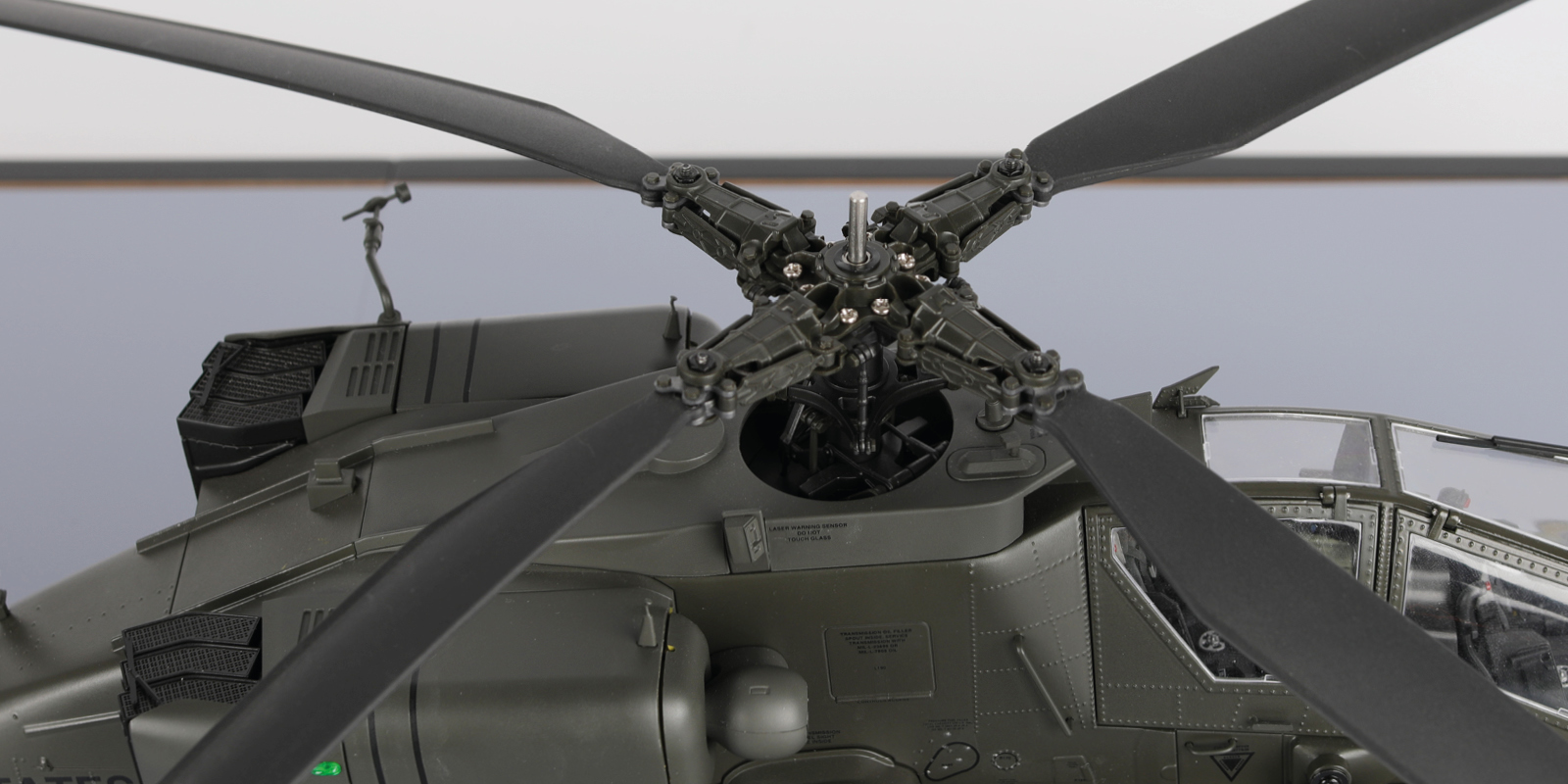
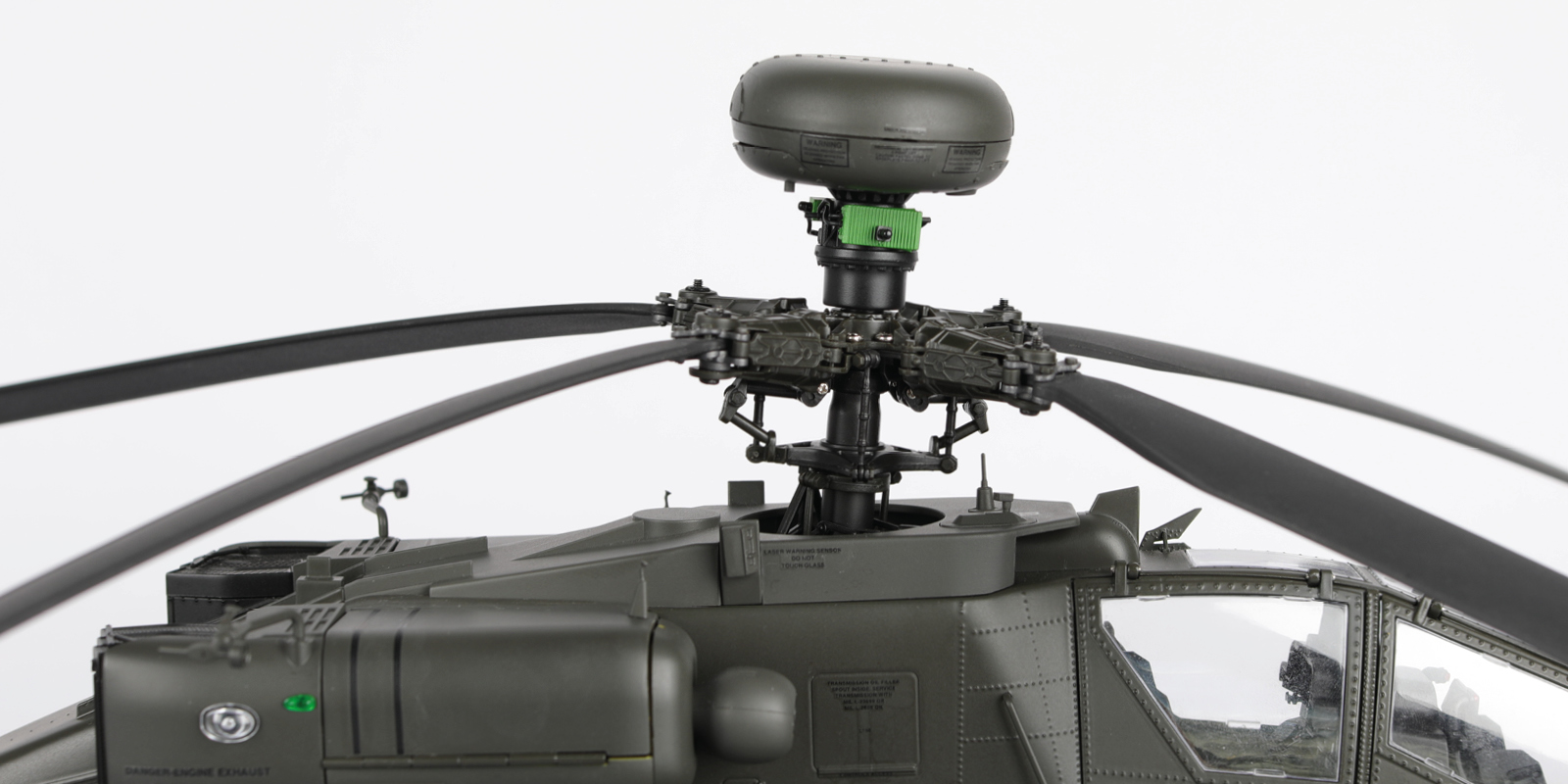
Fit the rotor blades (stage 86) to the assembly.
Step 13
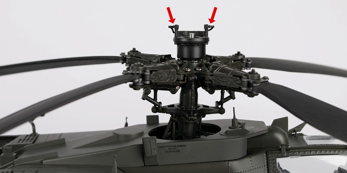
Fit the radar mount (stage 86) to the rotor blades.
Step 14
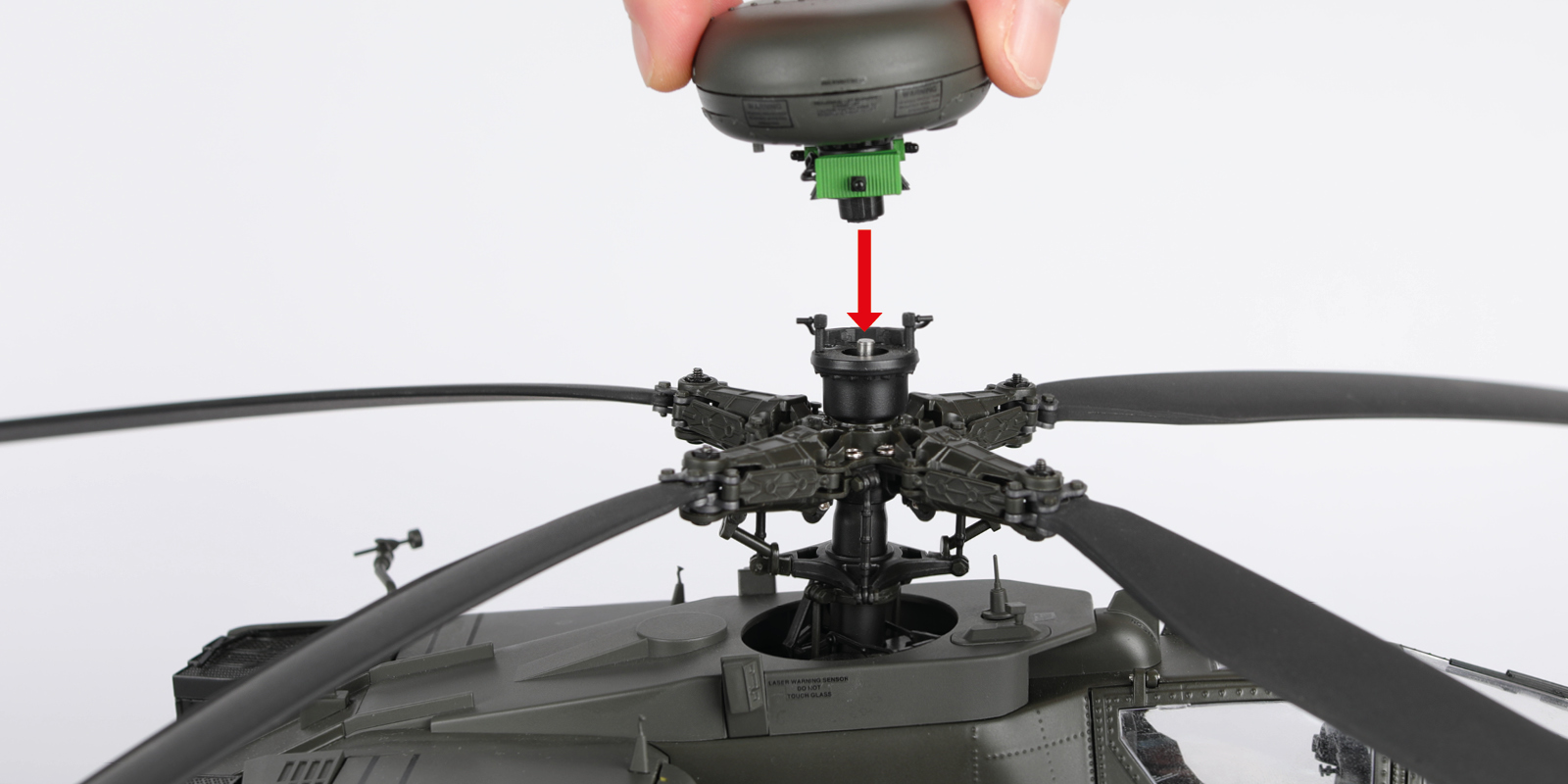
Fit the radar dome (stage 86) to the radar mount.
Note: If you need to work on the underside of the model, make sure to remove the radar dome and the rotor blades, keeping the rotor shaft in place.
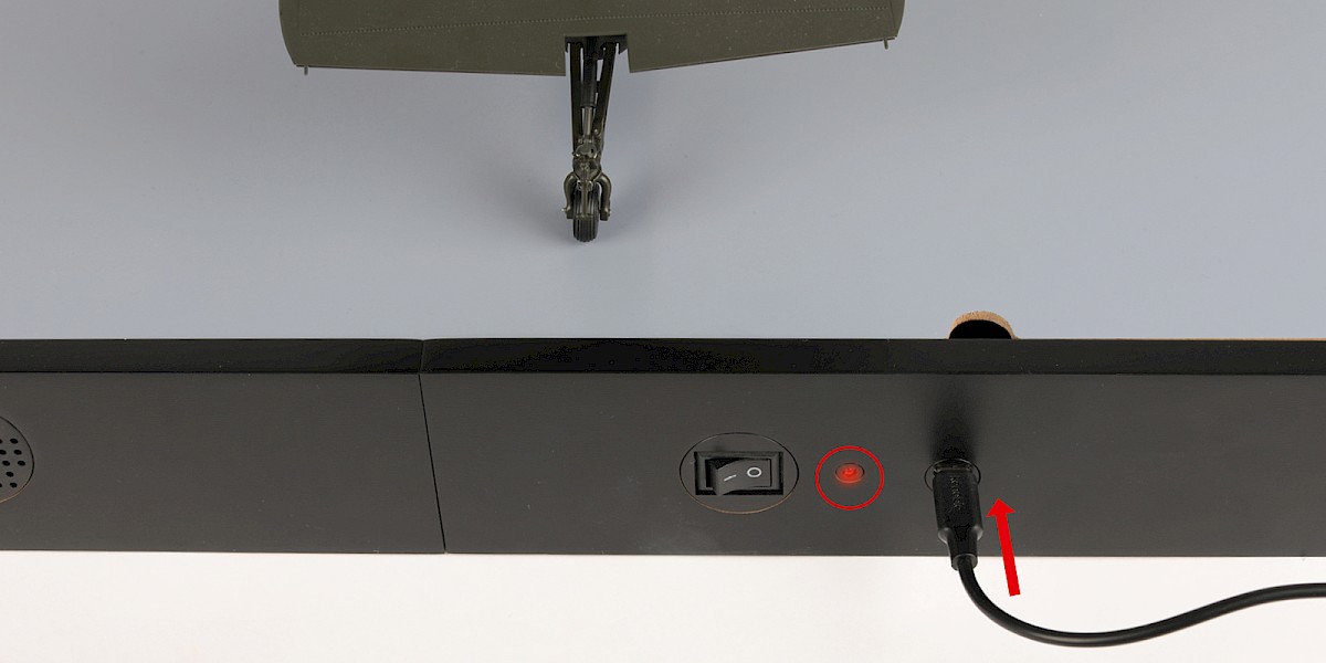
Step 15
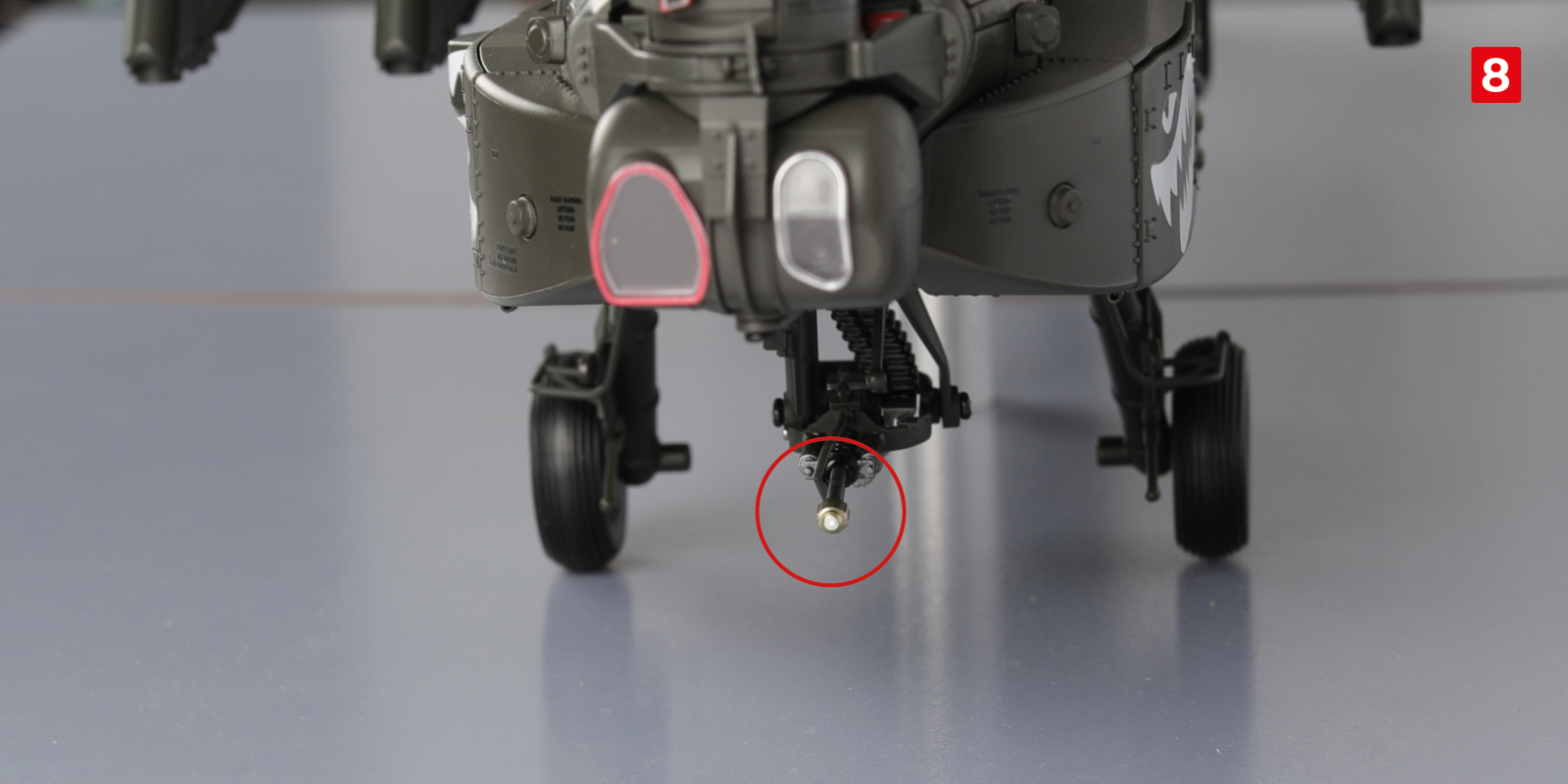
Operating the electronic functions.
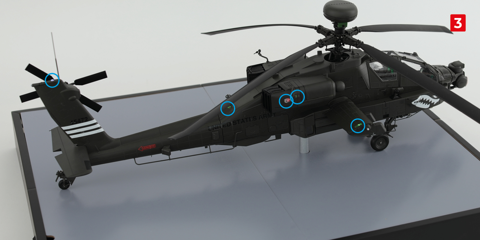
Charge the display base with a USB-C cable. The LED will light up while charging (circled).
Red light: charging
Blue light: fully charged
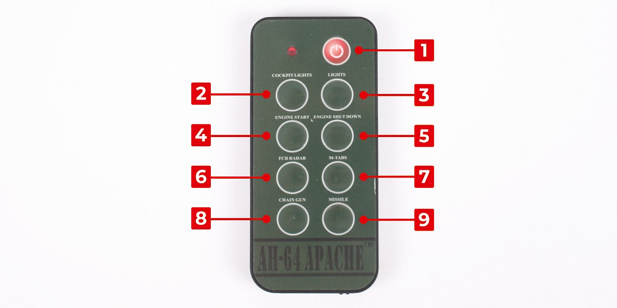
Step 16
Take the remote control (stage 59). Press the power button (1) to activate the remote control.
Step 17
Activate the display base by pressing the switch to the 'ON' position.
On the remote control, press the COCKPIT LIGHTS button (2) to activate the lights in the cockpit.
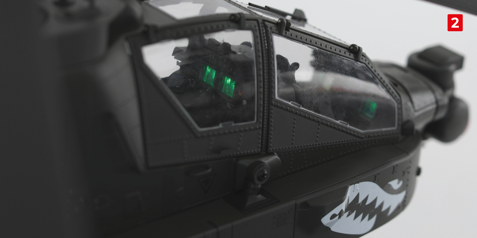
Step 18
Press the LIGHTS button (3) to activate the navigation lights (circled).
Step 19
Press the ENGINE START (4) button. The engine sound will begin to play and the rotors will start to spin.
Step 20
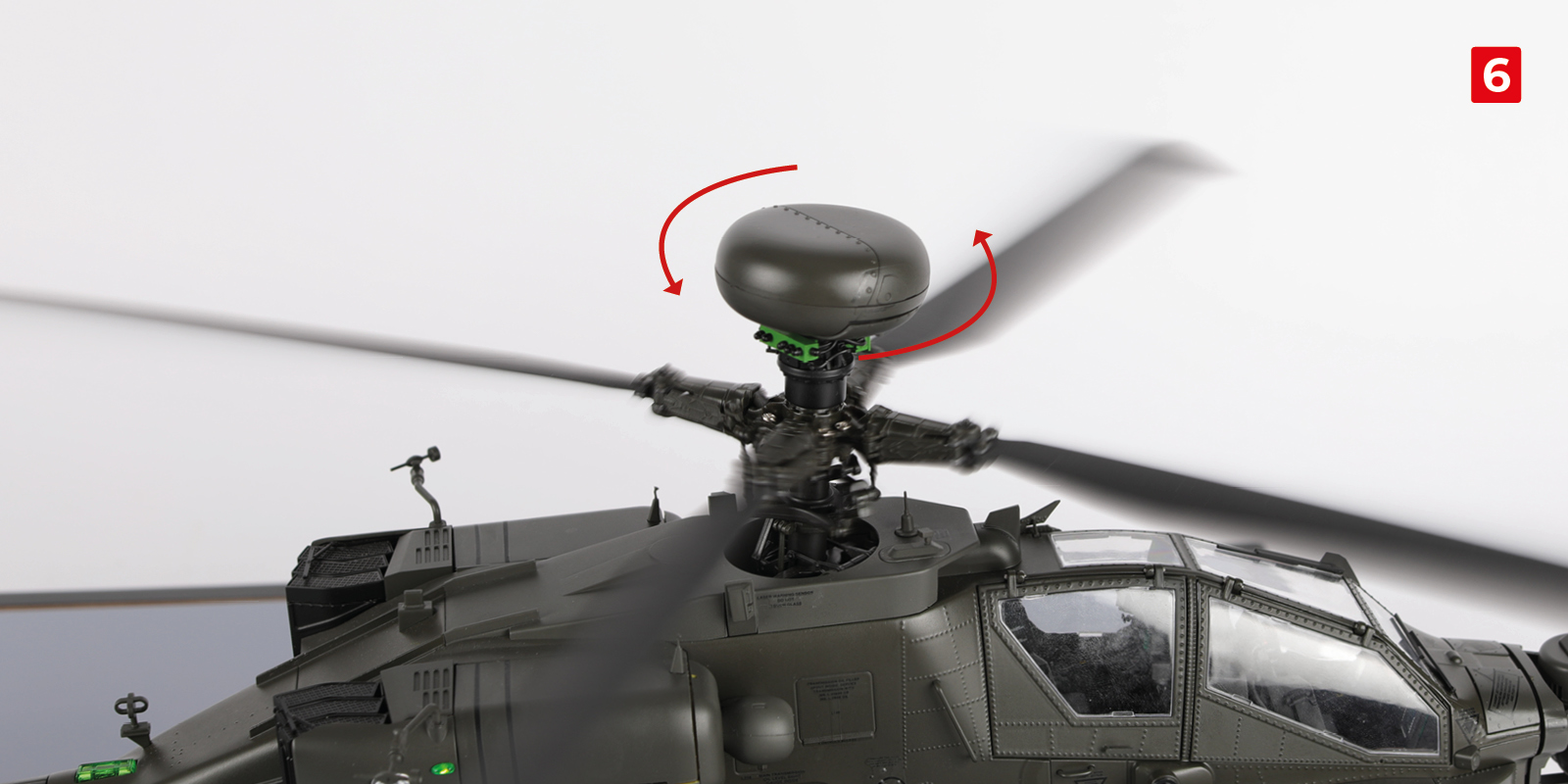
Press the FCR RADAR button (6). The radar dome will begin to spin.
Step 21
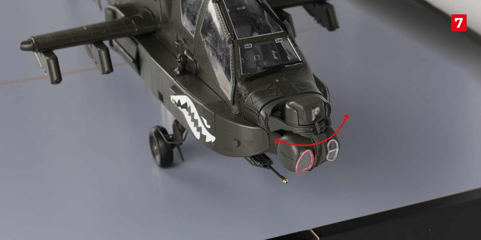
Press the M-TADS button (7). The M-TADS unit will begin to turn left and right.
Step 22
Hold down the CHAIN GUN button (8). The firing sound effect will play and the barrel light will flash.
Pressing the MISSILE button (9) will play a missile firing sound effect.
Pressing the ENGINE SHUT DOWN button (5) will stop the rotor blades. Switch off the remote control and the display base.
Step 23
The last few steps are to equip your Apache.
You can attach the various weapon systems and fuel tanks to the wing pylons with the magnets.
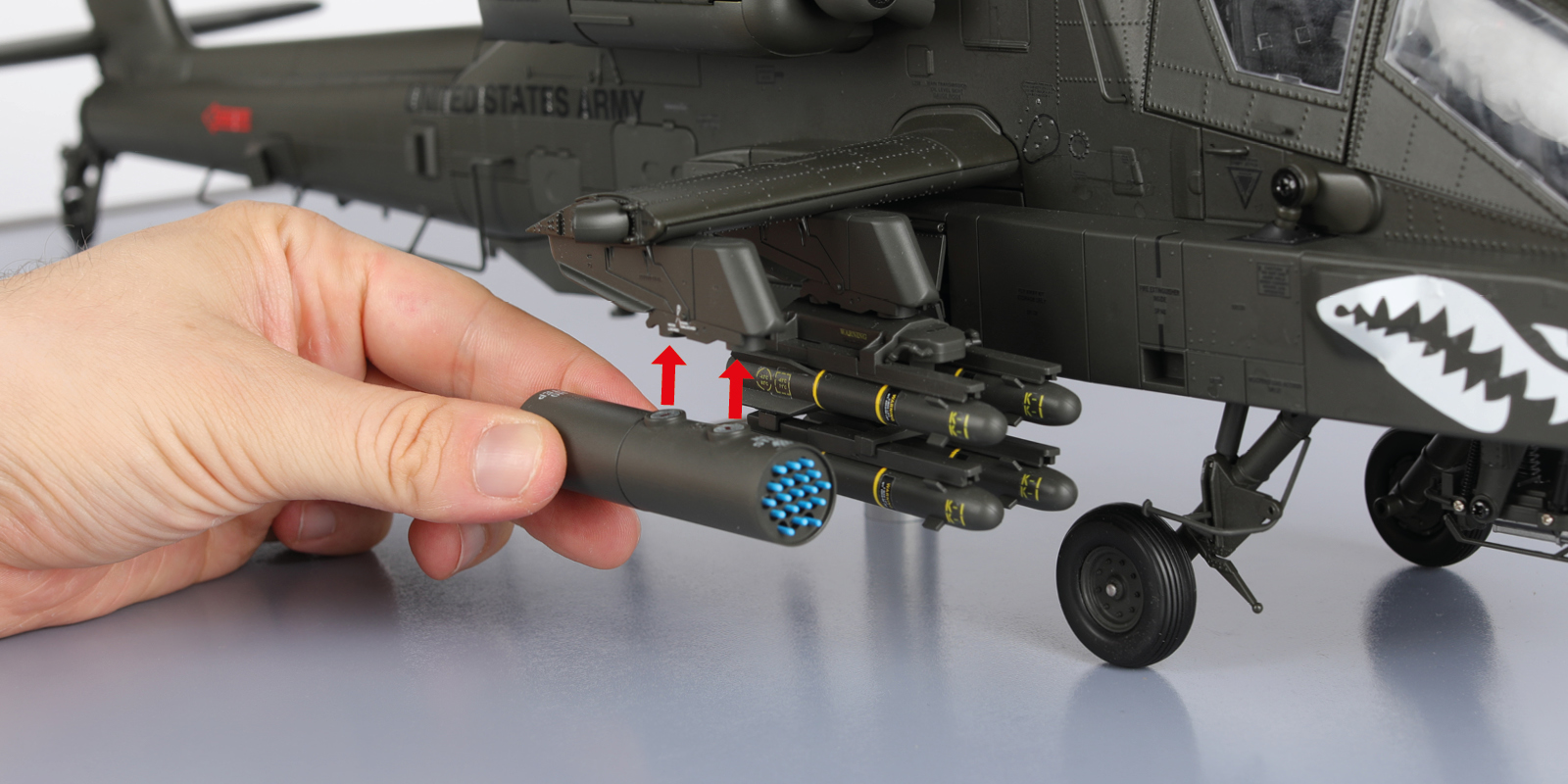
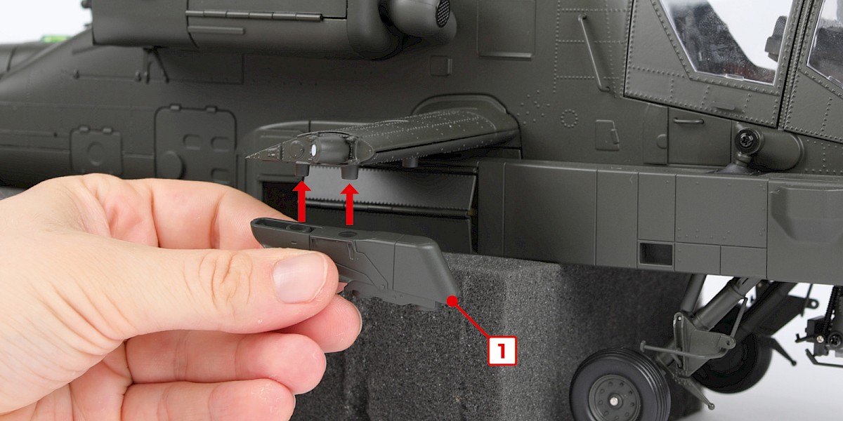
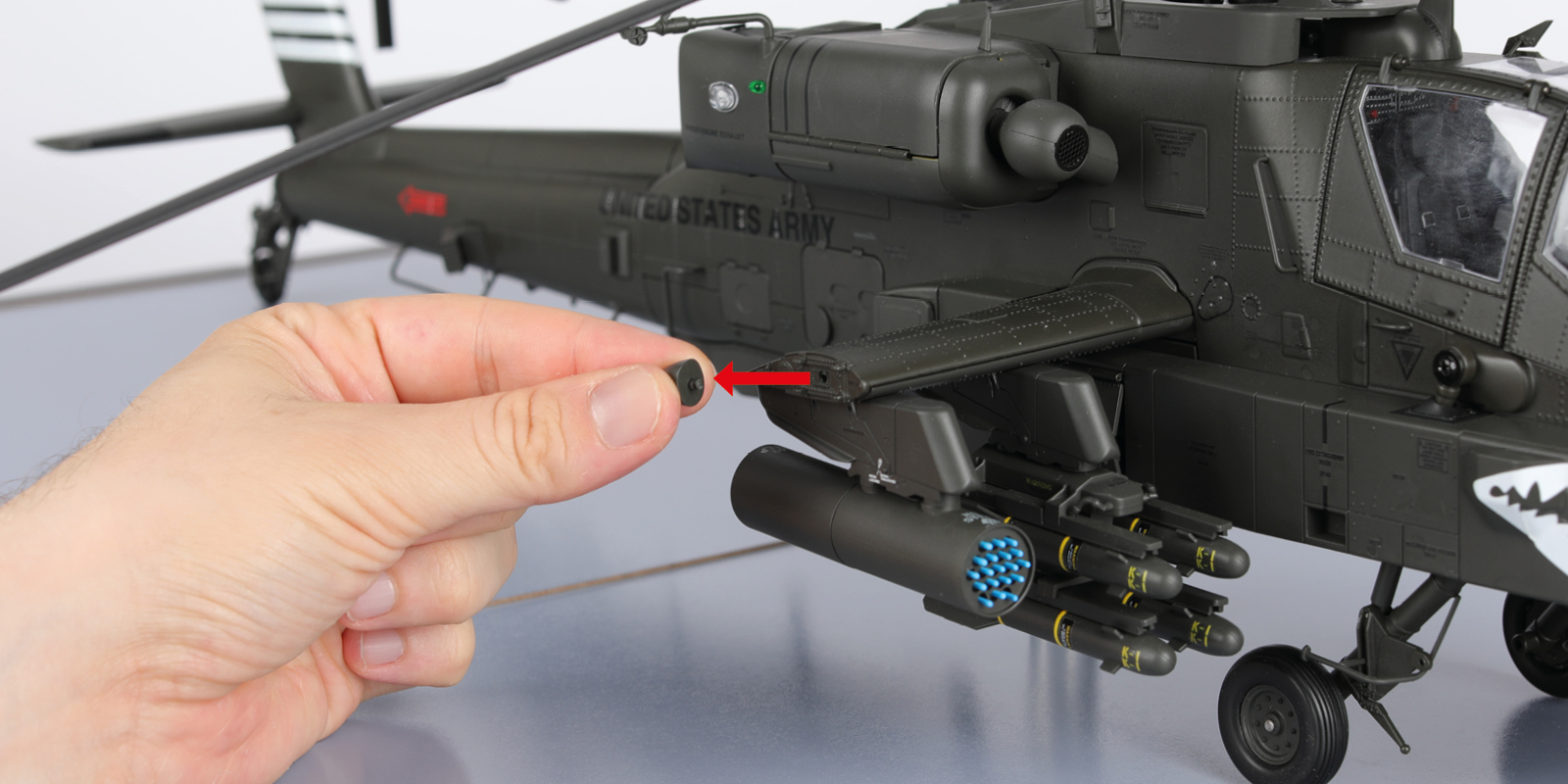
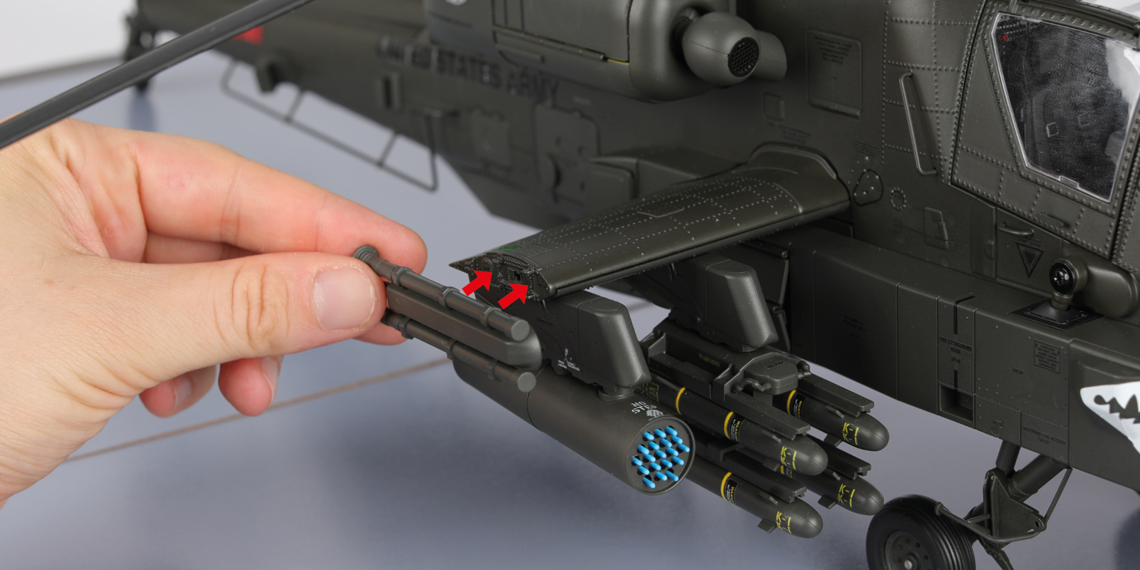
Step 24
To attach the Stinger missile launchers, remove the end of the wing and fit the launcher as shown.
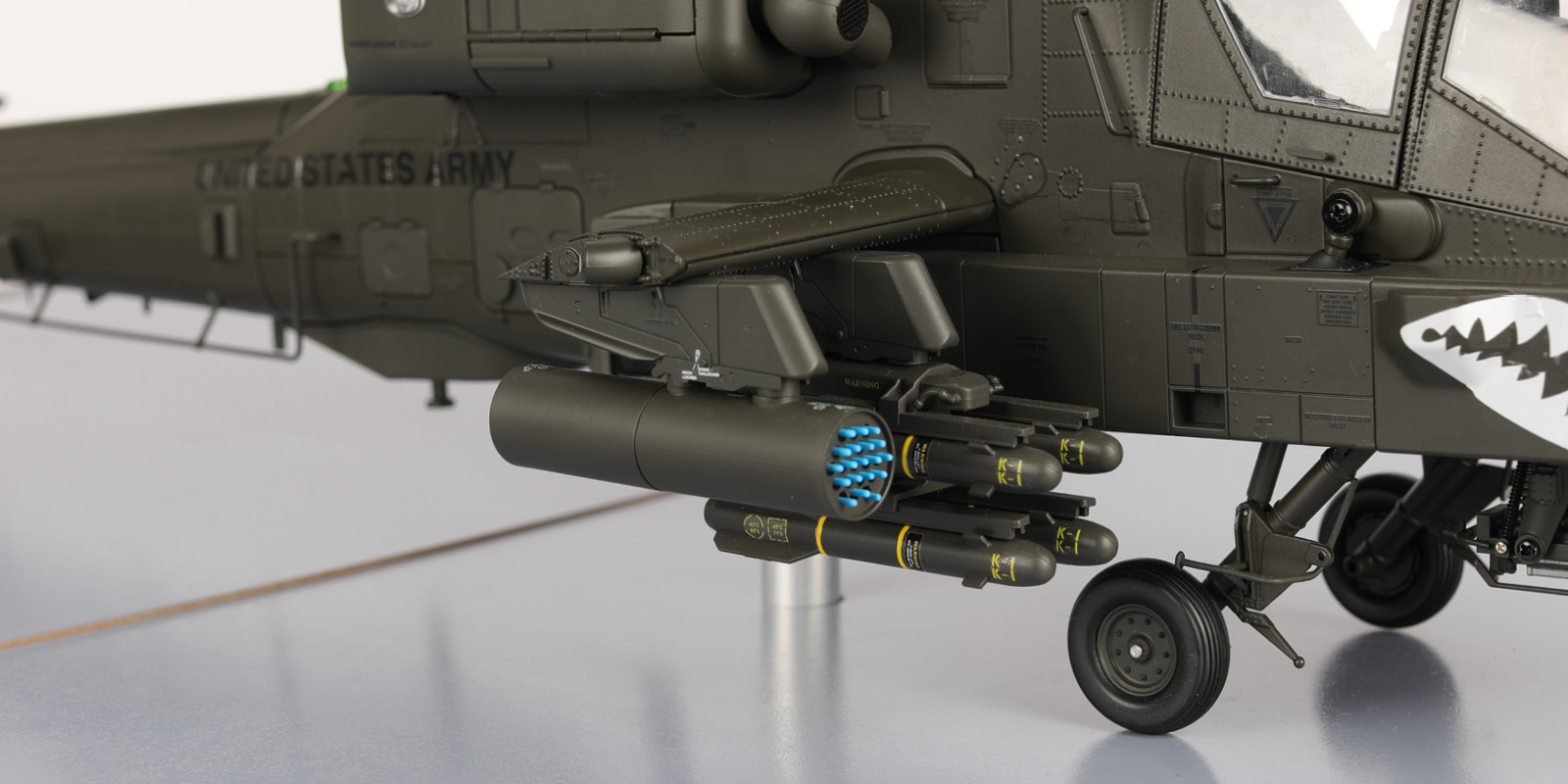
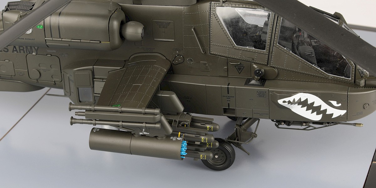
Step 25
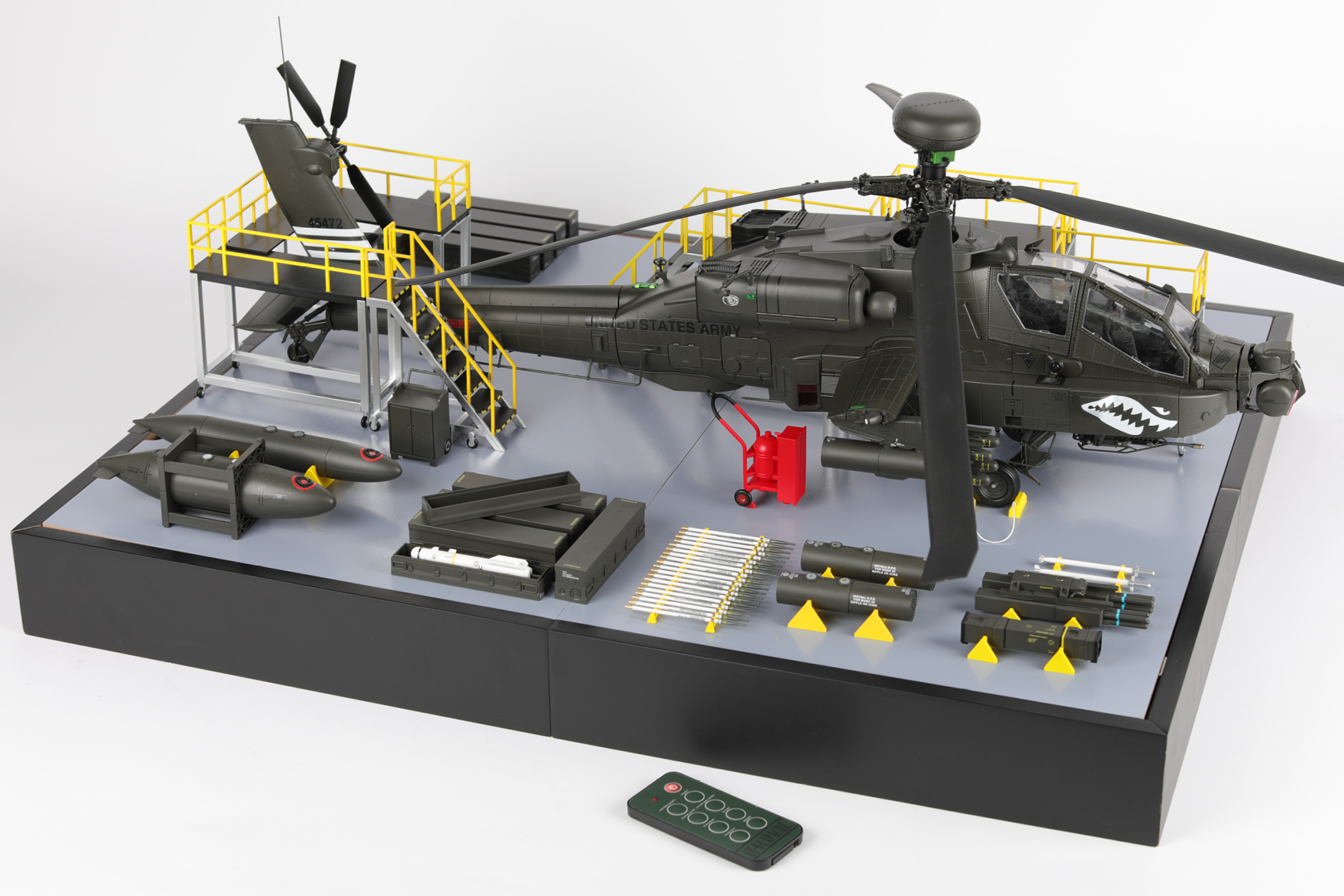
This is just one example of the many weapon configurations you can give your model.
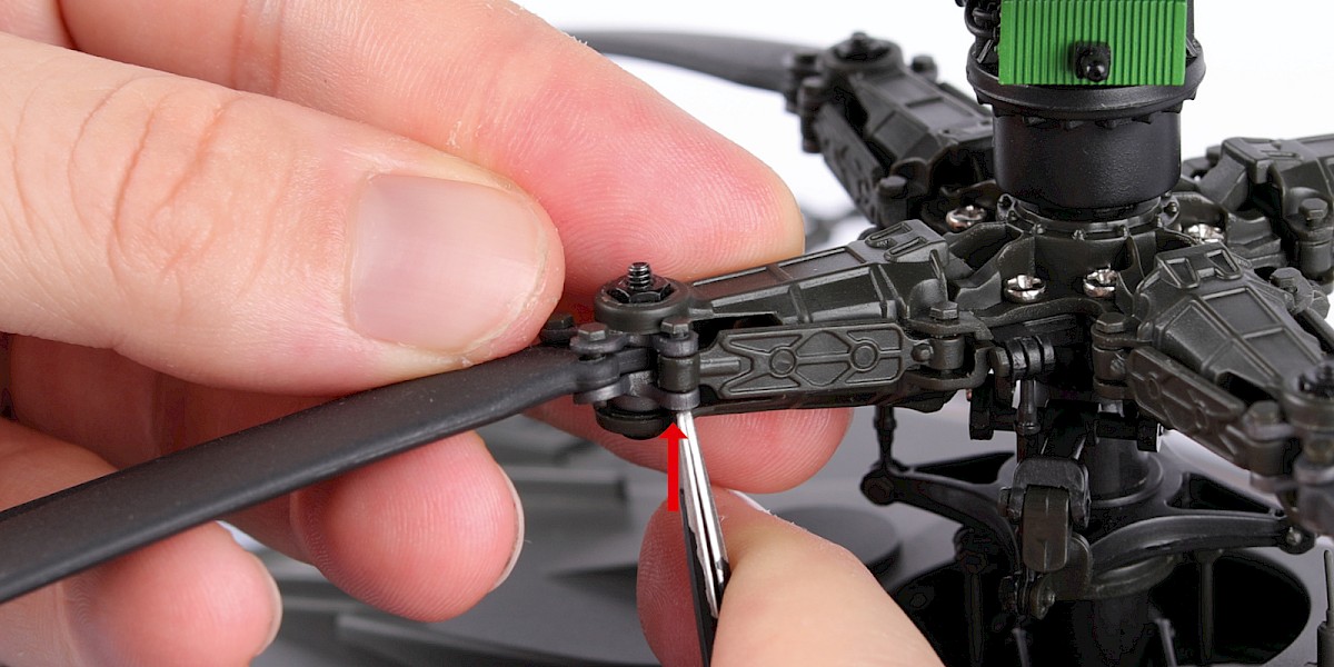
Step 26
The rotor blades can be folded.
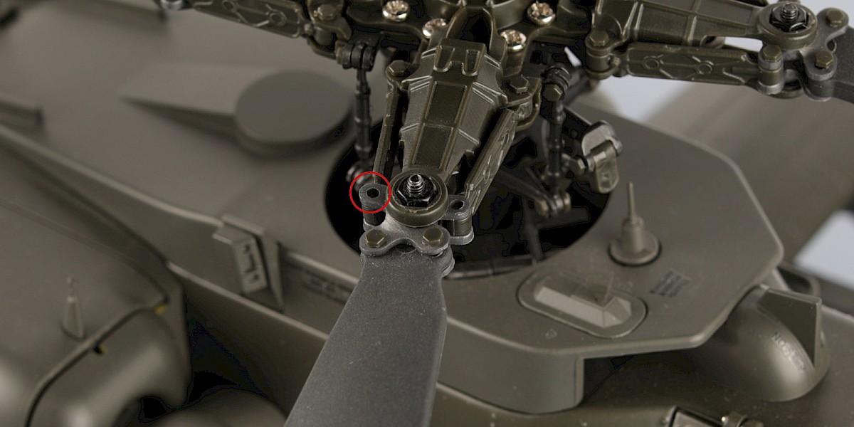
Press the pin from underneath then remove it using tweezers.
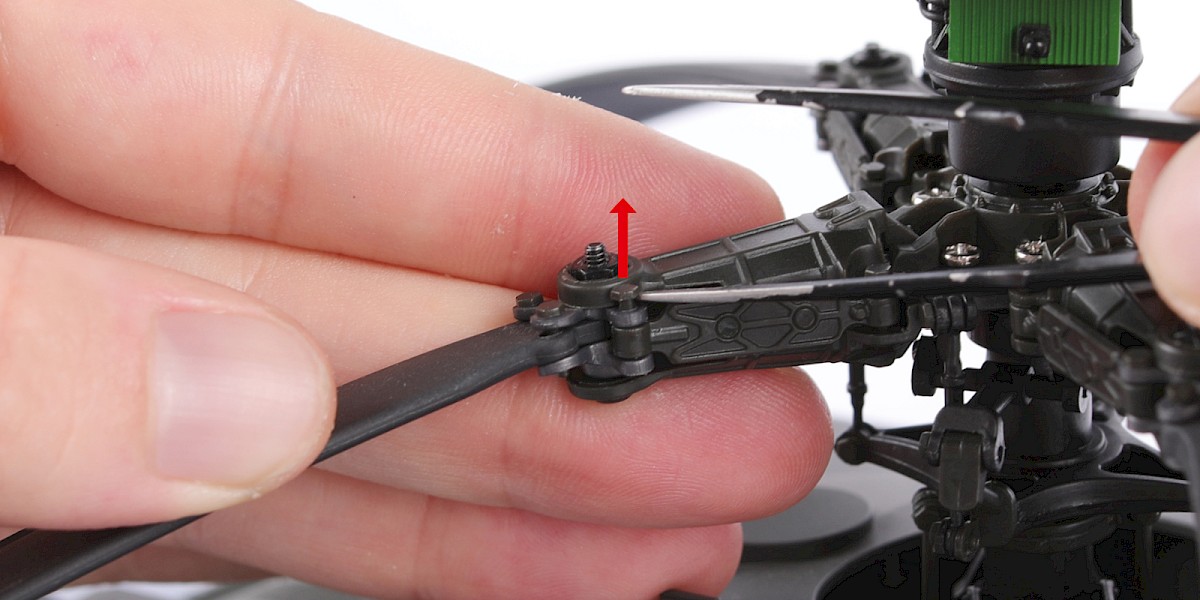
Step 27
Remove the pin from the other side (circled) in the same way.
Step 28
With the pins removed the rotor blade can be folded. Repeat this process on the other rotor blades to fold them away for storage.
Do not spin the rotor blades while the pins are removed.
STAGE COMPLETE
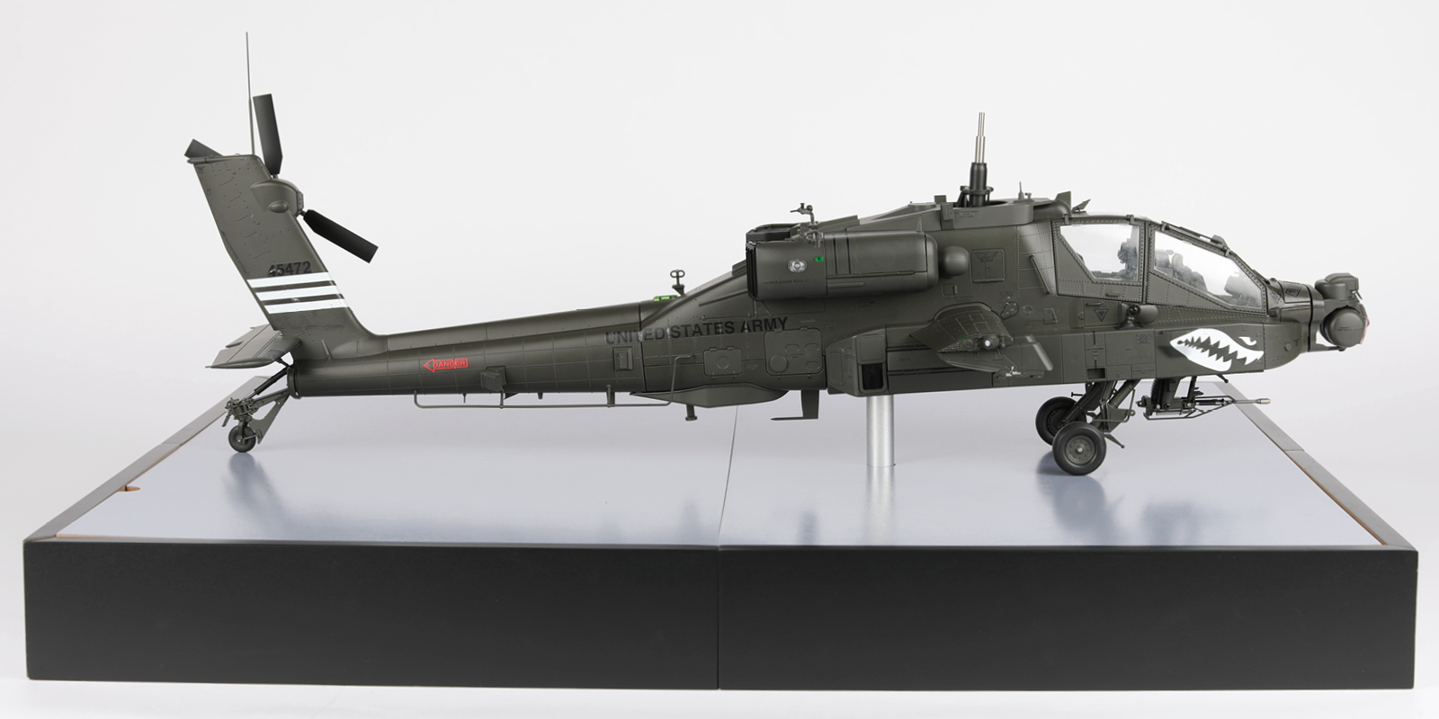
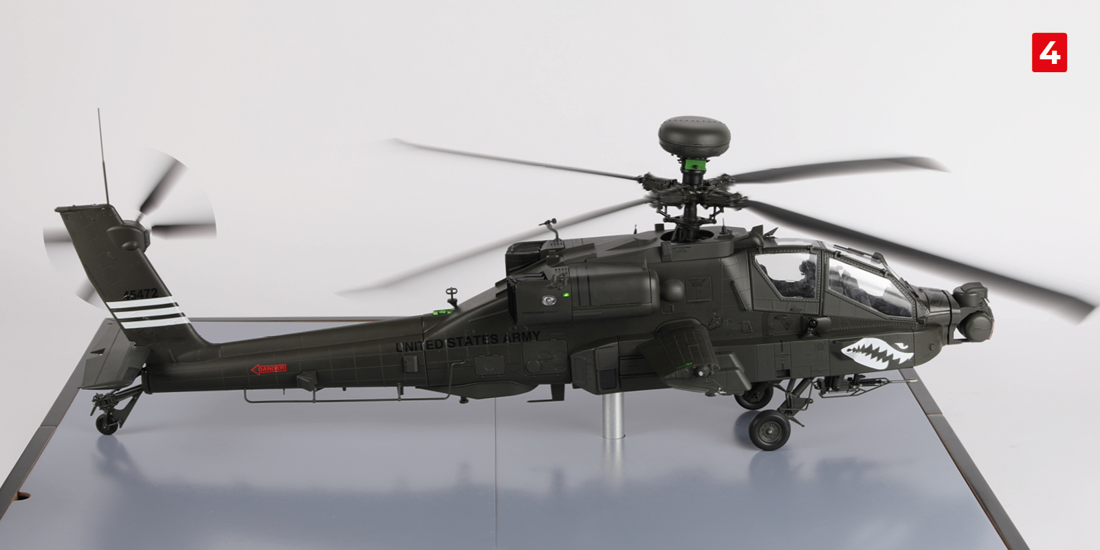
Your model is now complete!
Don’t forget, as an Agora Advantage Club member you will have Reward points to redeem. You may now have enough points to enjoy a free pack 1 for your next model.