Pack 10
BUILD INSTRUCTIONS
Instructions for building your USS Constitution model ship
Your model of the USS Constitution is divided into 12 packs.
You will need to follow the step-by-step assembly photos, the plans and the explanatory texts below.
Please save the leftover materials from each pack for use when instructed to do so at a later stage of the assembly instructions.
The IP sheets displayed below are drawings of laser-cut parts and photo-etched brass parts and will serve as a guide for identification of some parts.
Use the PARTS REFERENCE table to help locate the parts.
The PL-00 templates (printed at 1/1 scale) included in each pack will serve as a guide for building the model.
Please check the list below to ensure you have all the tools required for building your wooden ship.
When removing a part, cut the ribs that join the part to the wooden plate with a cutter.
Remove the parts carefully so as not to break them.
Keep and store the parts in their frames. Only remove the parts you are working on in each step.
Extra support can be found on our forum or from the Expert Directory page of our website.
PARTS LIST
| Material | Quantity | |
| Thread | ||
| ø0.15 x 25,000 mm (C) | Cotton | 1 |
| ø1.5 x 4,000 mm (brown) | Cotton | 1 |
| Other Parts | ||
| Port bow ornament | 1 | |
| Starboard bow ornament | 1 | |
| Large railing end ornament (port and starboard) | 3 | |
| Small railing end ornament (port and starboard) | 2 | |
| Mesh sheet 150 x 200 mm | 2 | |
| Deadeye ø5 mm (G) | 115 | |
| Deadeye ø4 mm (F) | 115 | |
| Anchor 55 mm | 4 | |
| Strip 2 x 100 mm | Brass | 5 |
| Ring ø8 mm | Brass | 15 |
| Railing stanchions | Brass | 68 |
| Mast band 2 x 11 mm | Brass | 8 |
| Mast band 2 x 13 mm | Brass | 4 |
| Fabric 200 x 200 mm | 1 |
Tools you will need: cutting mat, pencil, cutting knife, fine-grit sandpaper or sponge sandpaper, file, white wood glue, super glue (cyanoacrylate glue), masking tape, set square, hacksaw, sanding block, 30 cm steel ruler, clamps, drill, moulding scriber tool
PARTS REFERENCE
PART NO. | IP-SHEET LOCATION | PART NO. | IP-SHEET LOCATION |
| 10.13 | 2001-32 | 10.31 | 2001-22 |
| 10.22 | 2001-28 | 10.32 | 2001-22 |
| 10.23 | 2001-28 | 10.33 | 2001-22 |
| 10.30 | 2001-22 |
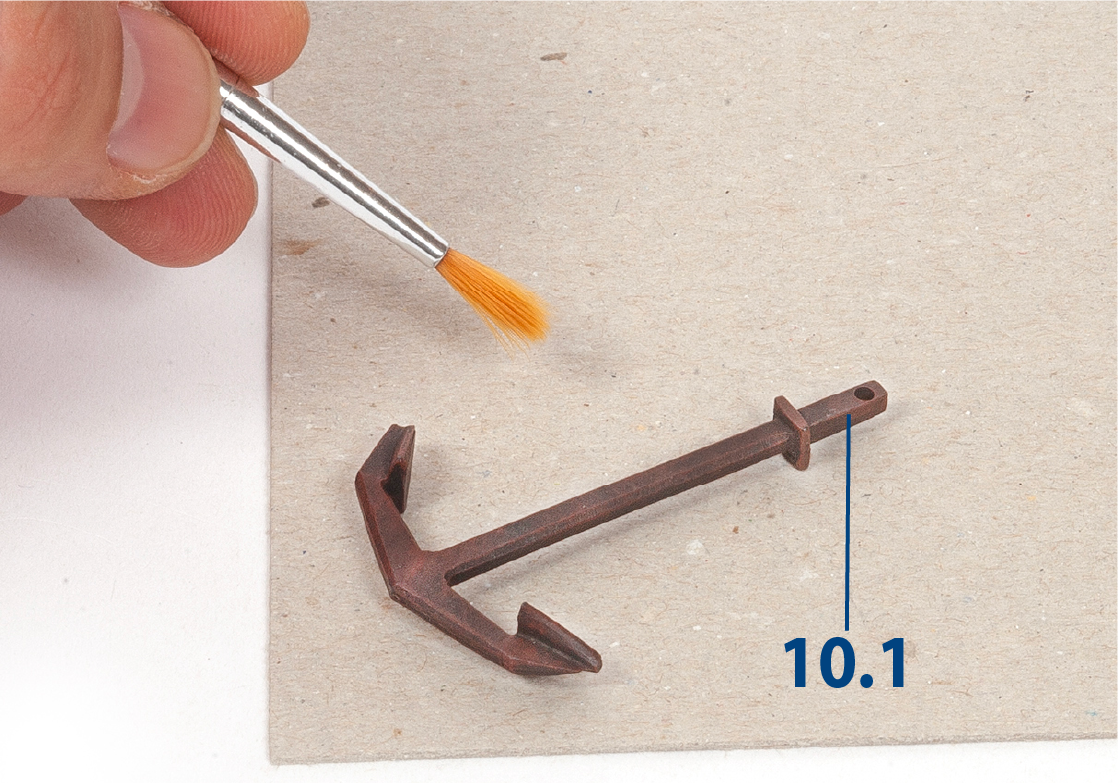
Step 1
If you would like to change the colour of the anchors, paint parts 10.1 black. When the paint is dry, drybrush the parts with red paint.

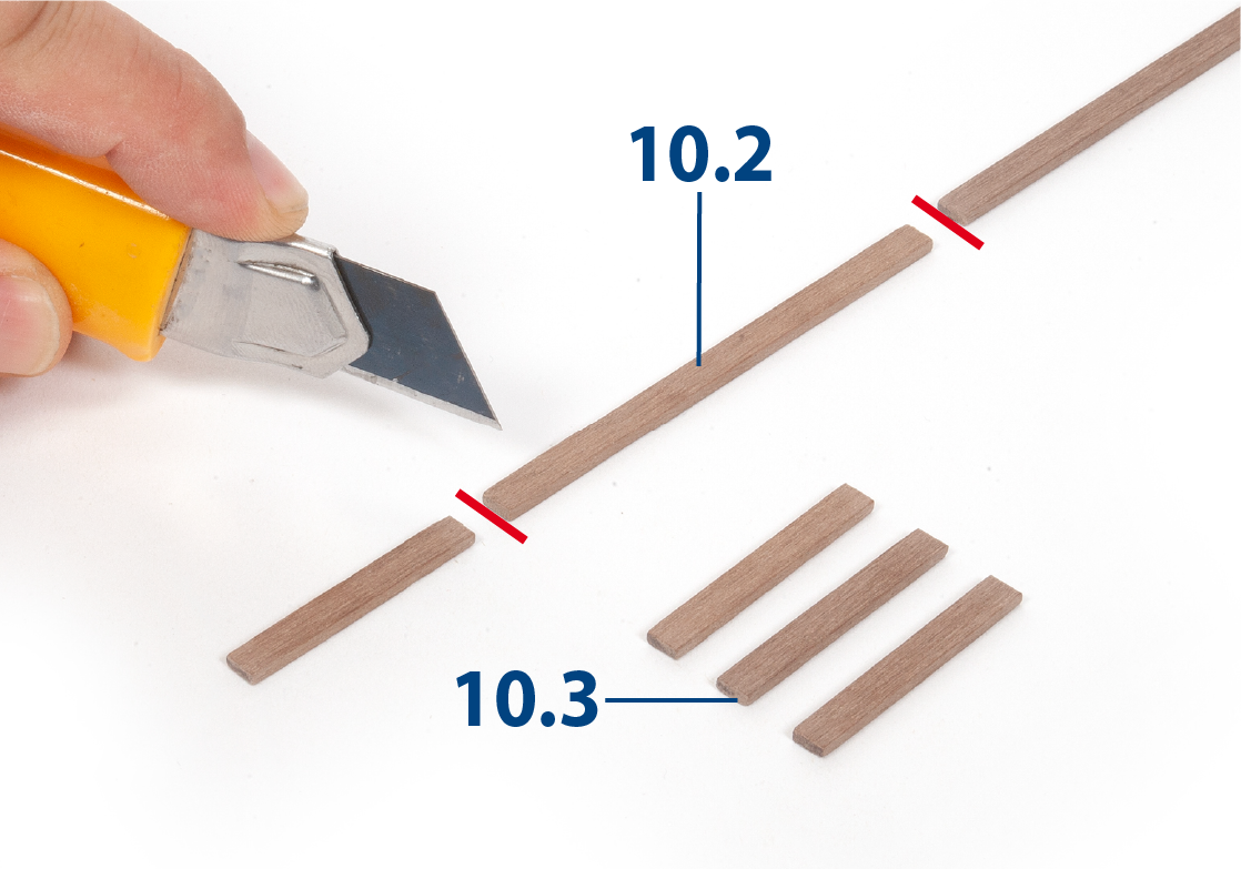
Step 2
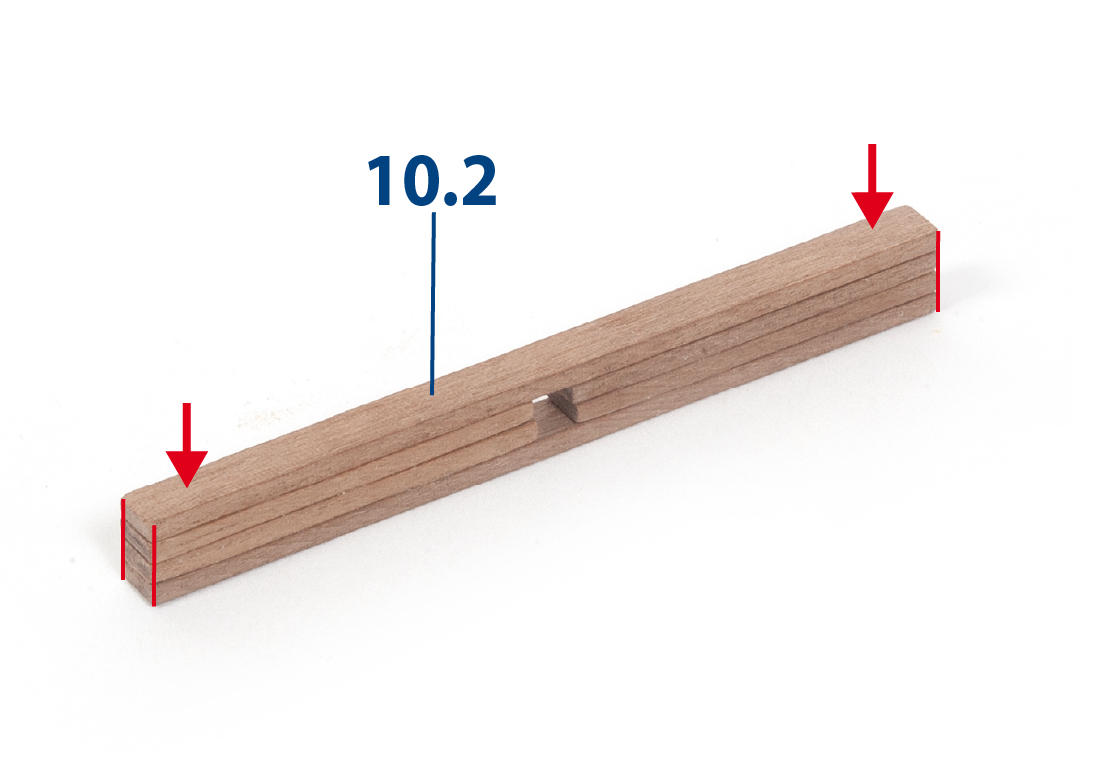
Cut to length eight parts 10.2 (2 x 5 x 54 mm African walnut) and sixteen parts 10.3 (2 x 5 x 25 mm African walnut).
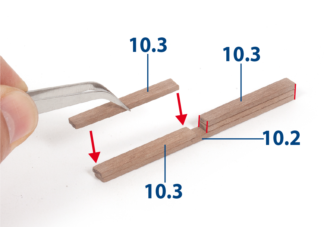
Step 3
Glue four parts 10.3 to one part 10.2 as shown.
Step 4
Glue one part 10.2 on top.
Step 5
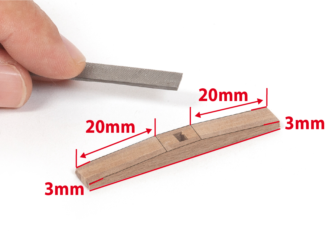
Use a cutting tool or file to shape the parts as shown in the image.
Step 6
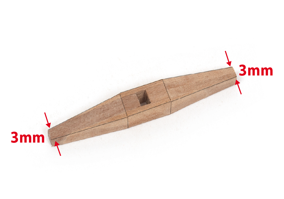
Continue to file the parts to shape as shown. Repeat steps 3–6 to make four assemblies.
Step 7
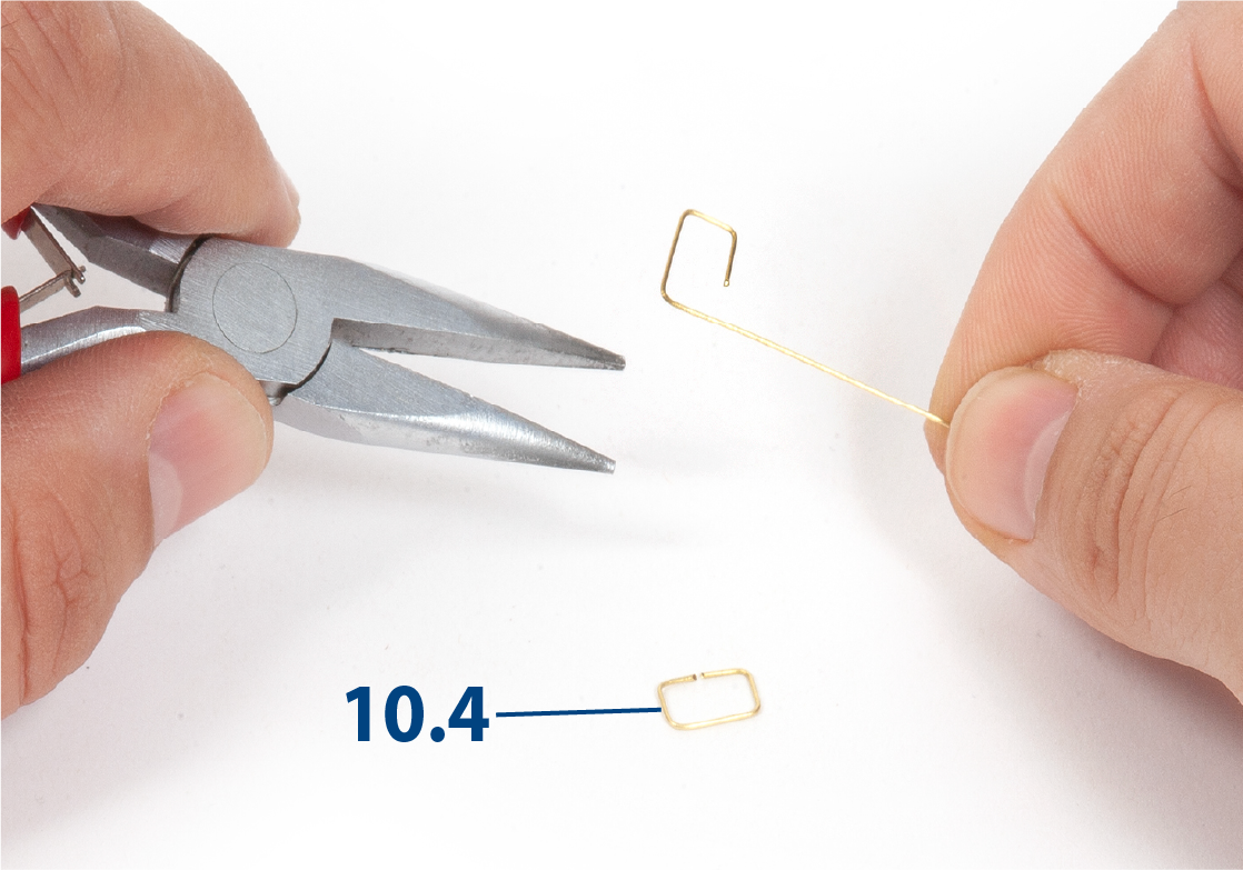
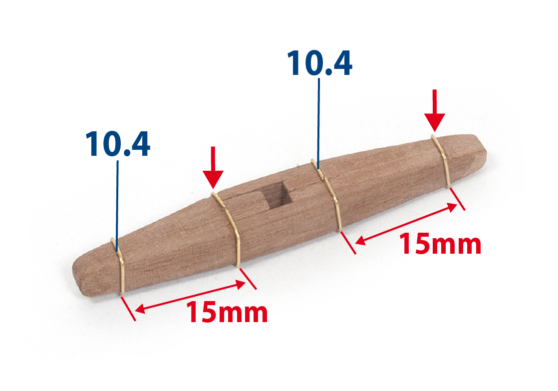
Shape sixteen parts 10.4 (ø0.5 x 30 mm) using pliers.
Step 8
Fit and secure parts 10.4 onto each of the assemblies.
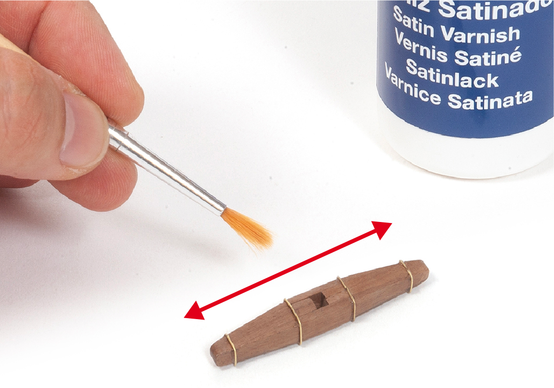
Step 9
Varnish all four assemblies.
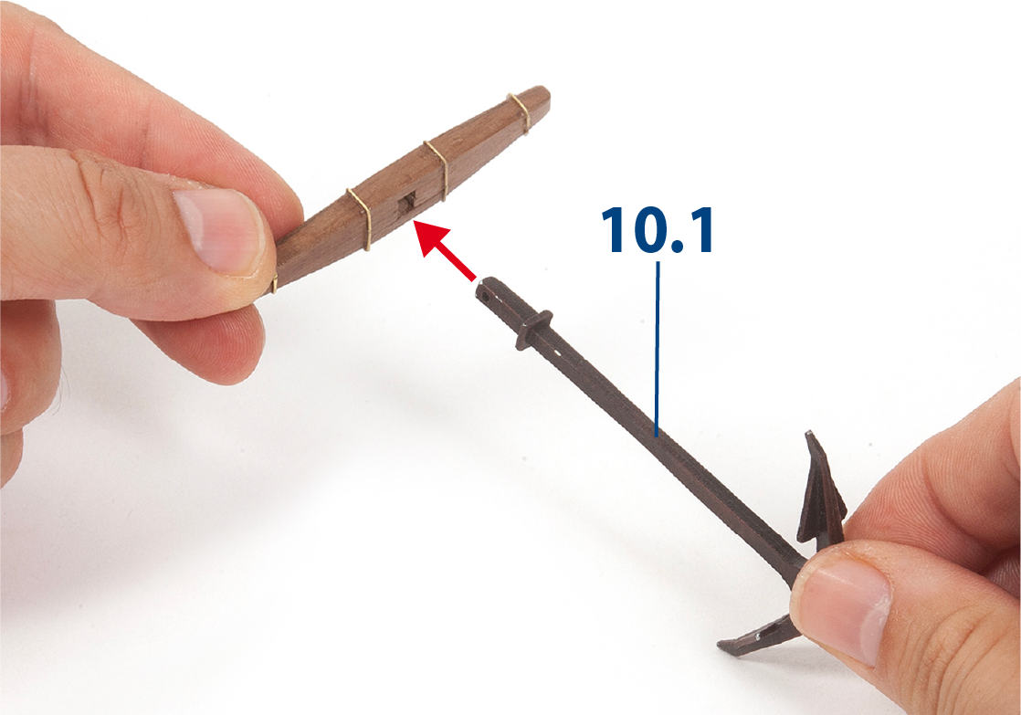
Step 10
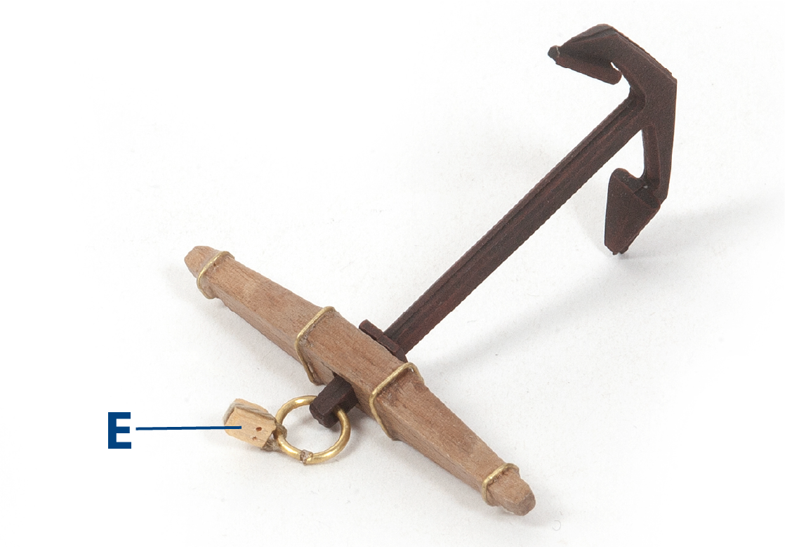
Fit an anchor 10.1 into each assembly.
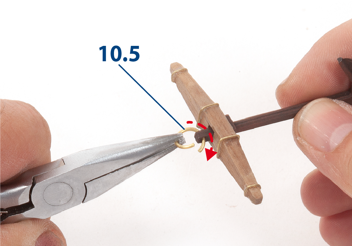
Step 11
Open a ring 10.5 (ø8 mm), pass it through the anchor's eye, and close it. Repeat for each anchor.
Step 12
Tie a piece of thread C (ø0.15 mm) around a block E (supplied in pack 7 and 9).
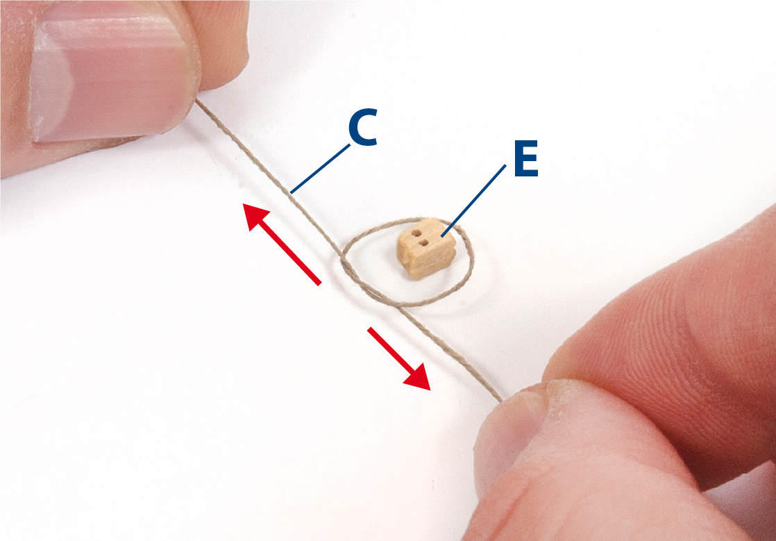
Step 13
Pull the thread tight and apply a drop of glue to secure the knot.
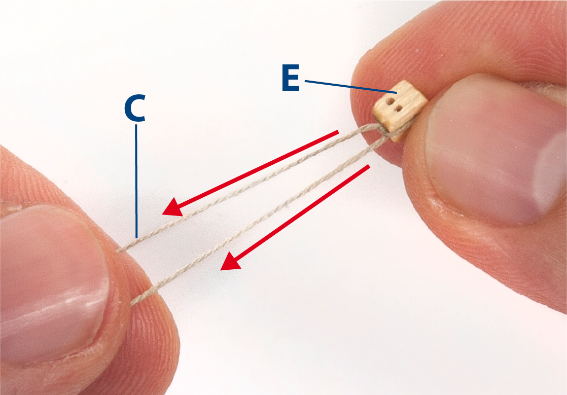
Step 14
Tie the block to the anchor ring as shown.
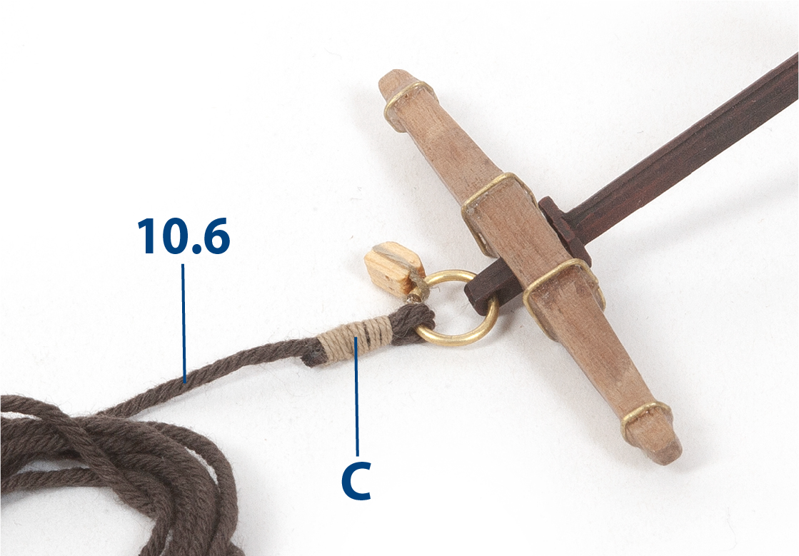
Step 15
Pass a 10.6 thread (ø1.5 x 250 mm, brown) through the anchor ring and fold it back, then wrap thread C around the connection to reinforce it. Repeat for each anchor.
Step 1
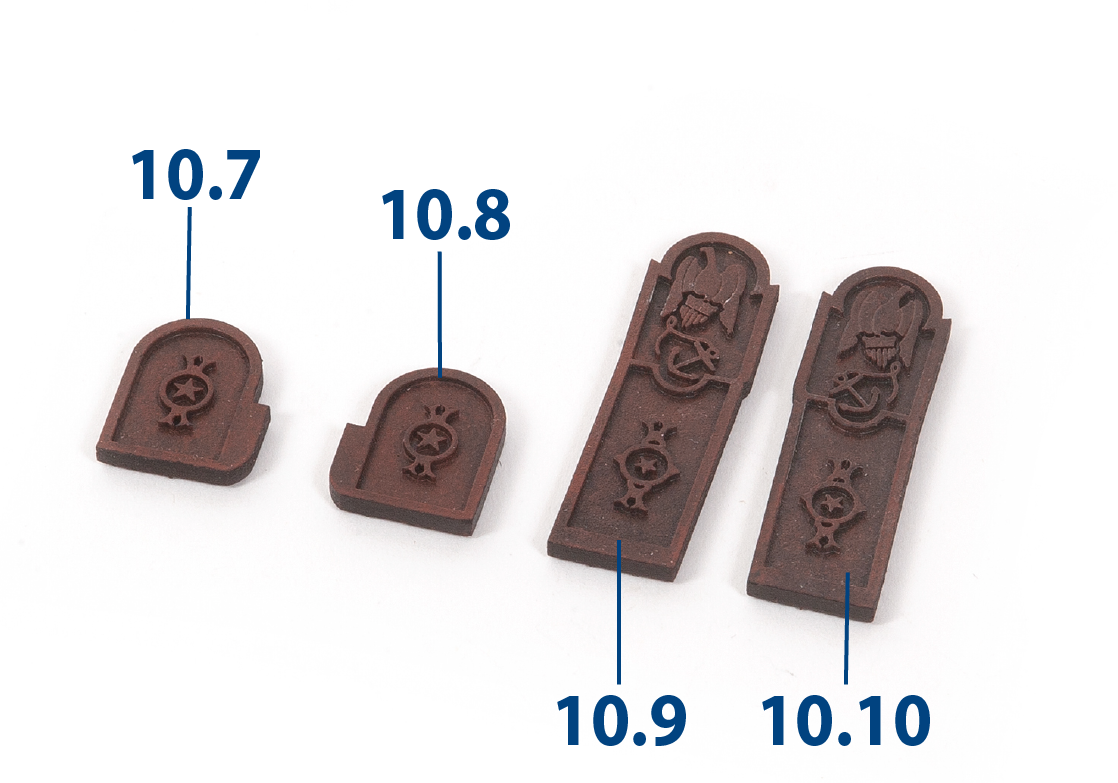
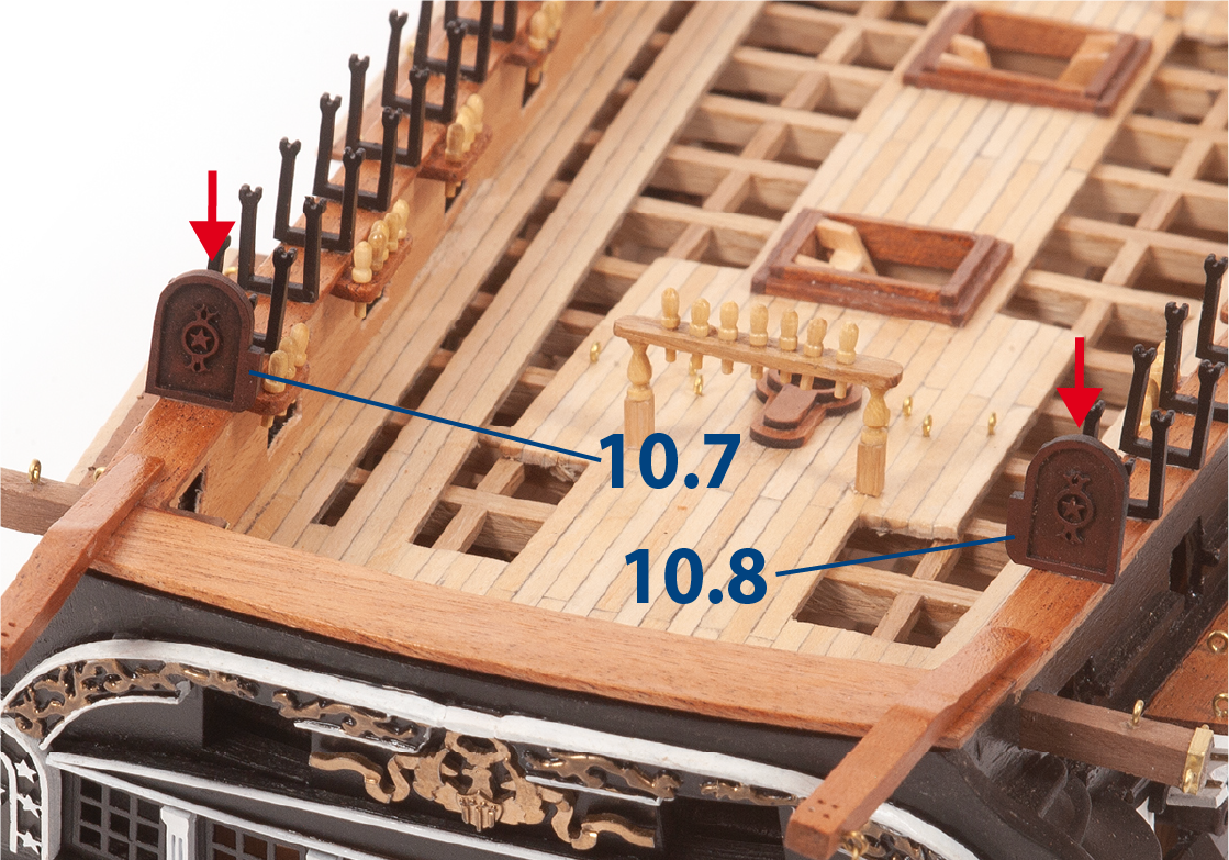
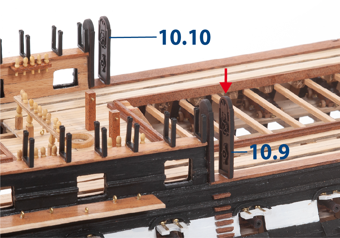
Cut out parts 10.7–10.10 (railing end ornaments) and smooth the edges if needed. Paint the parts black, then drybrush them with red paint.
Step 2
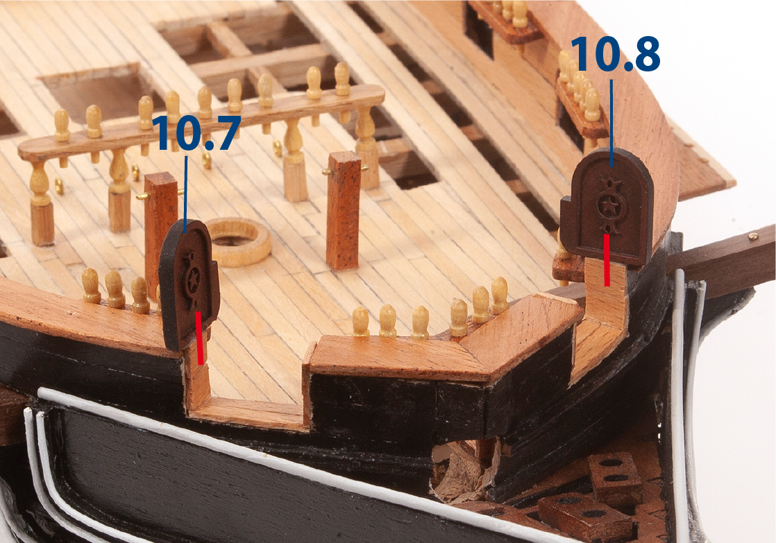
Fit and glue parts 10.7 and 10.8 onto the forward bulwarks.
Step 3
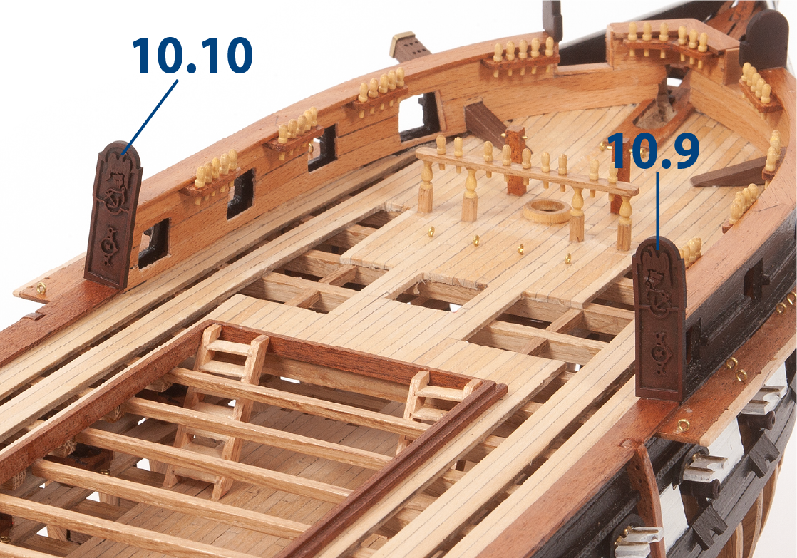
Glue parts 10.9 and 10.10 to the forward bulwarks as shown.
Step 4
Glue parts 10.9 and 10.10 to the aft bulwarks as shown.
Step 5
Paint parts 10.11 and 10.12 (bow ornaments) in black and white.
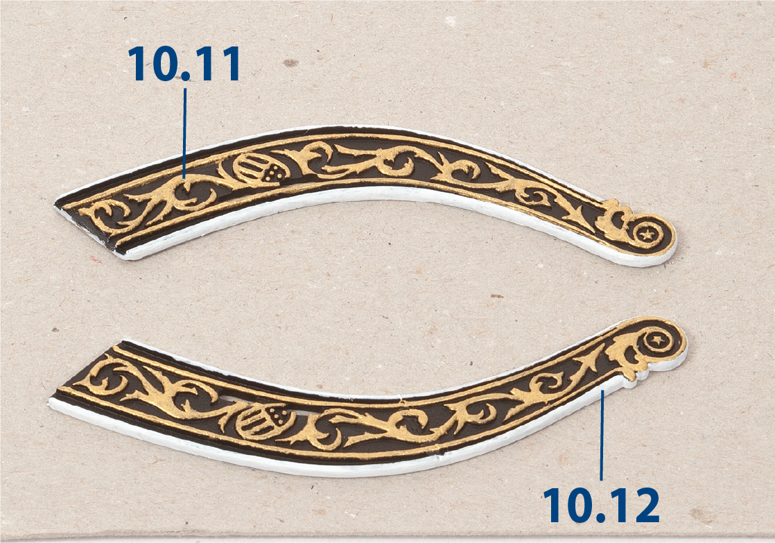
Step 6
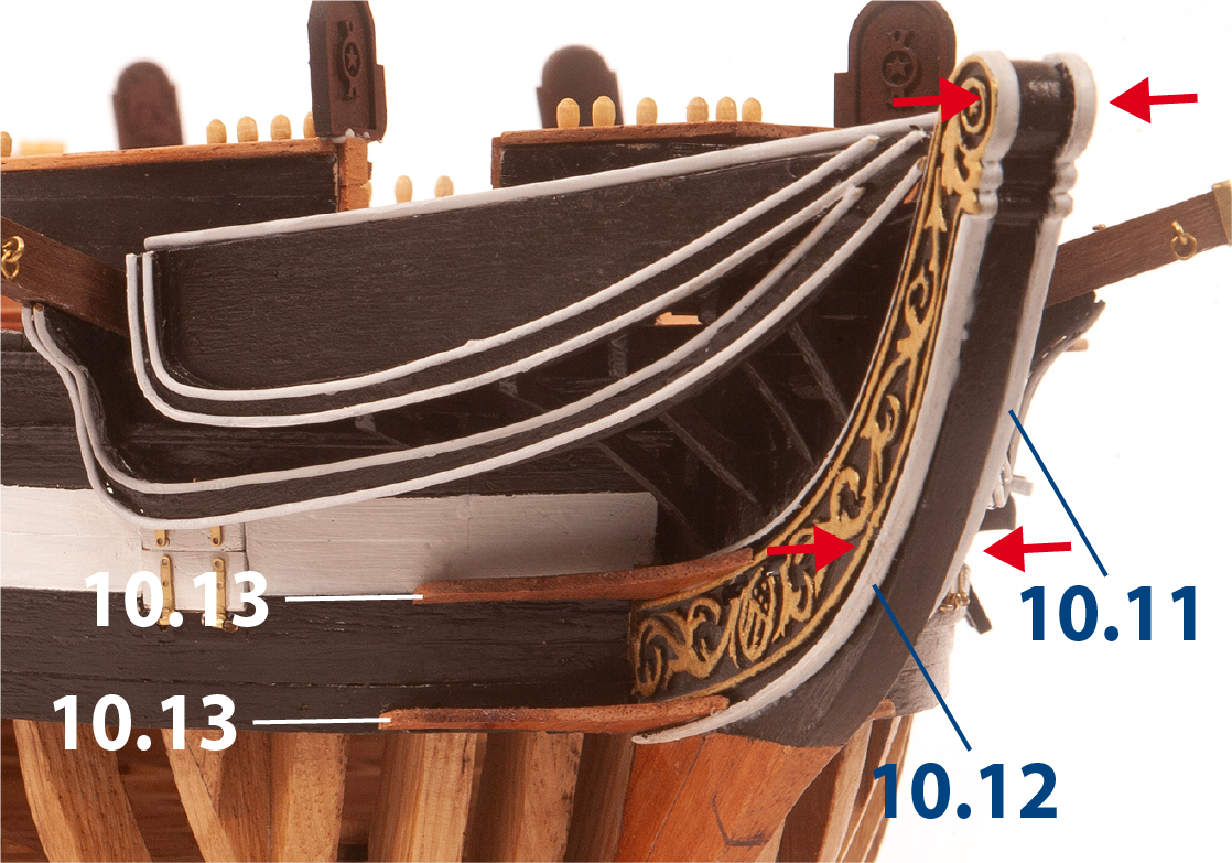
Fit parts 10.11 and 10.12 to the hull, making a recess in the hull planking if needed. Then, fit and glue parts 10.13 on each side of the stem.
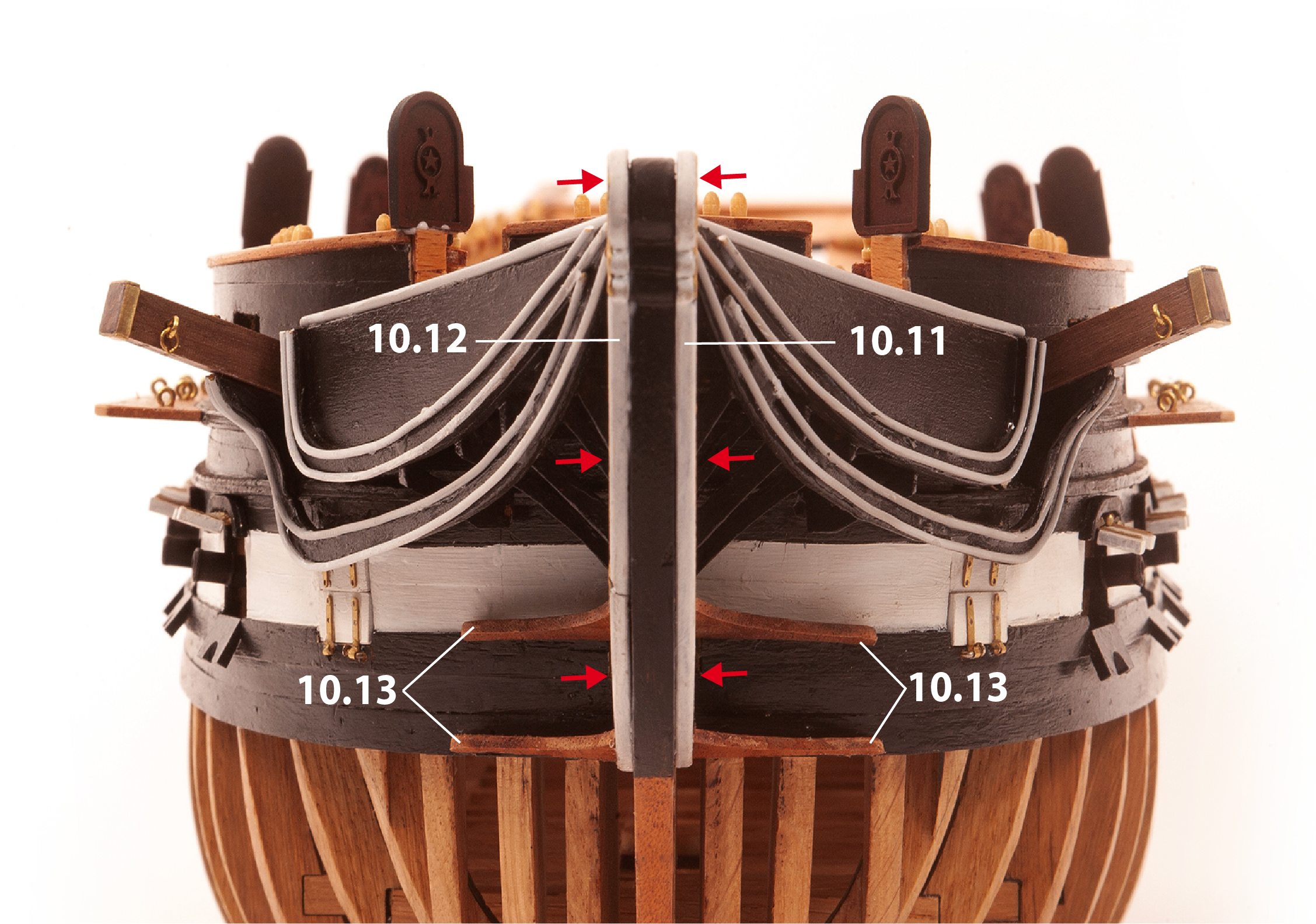
Step 7
This front view shows the parts in place.
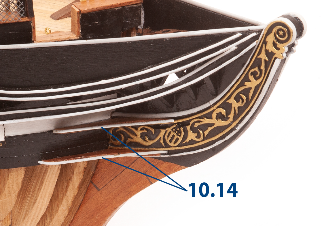
Step 8
Cut two parts 10.14 (ø1 × 53 mm brass), paint them white, then glue them in place following the edge as shown.
Repeat this process on the other side of the hull.
Step 9
Using the deck plan, mark the positions for part 10.15 (railing stanchions) with a punch or similar tool.
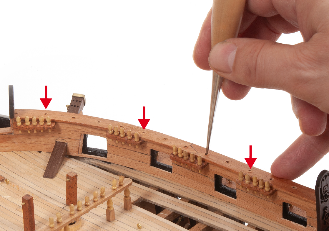
Step 10
Drill ø1.5 mm holes for parts 10.15.

Step 11
Paint parts 10.15 black, then fit and glue parts 10.15 in the bow area.
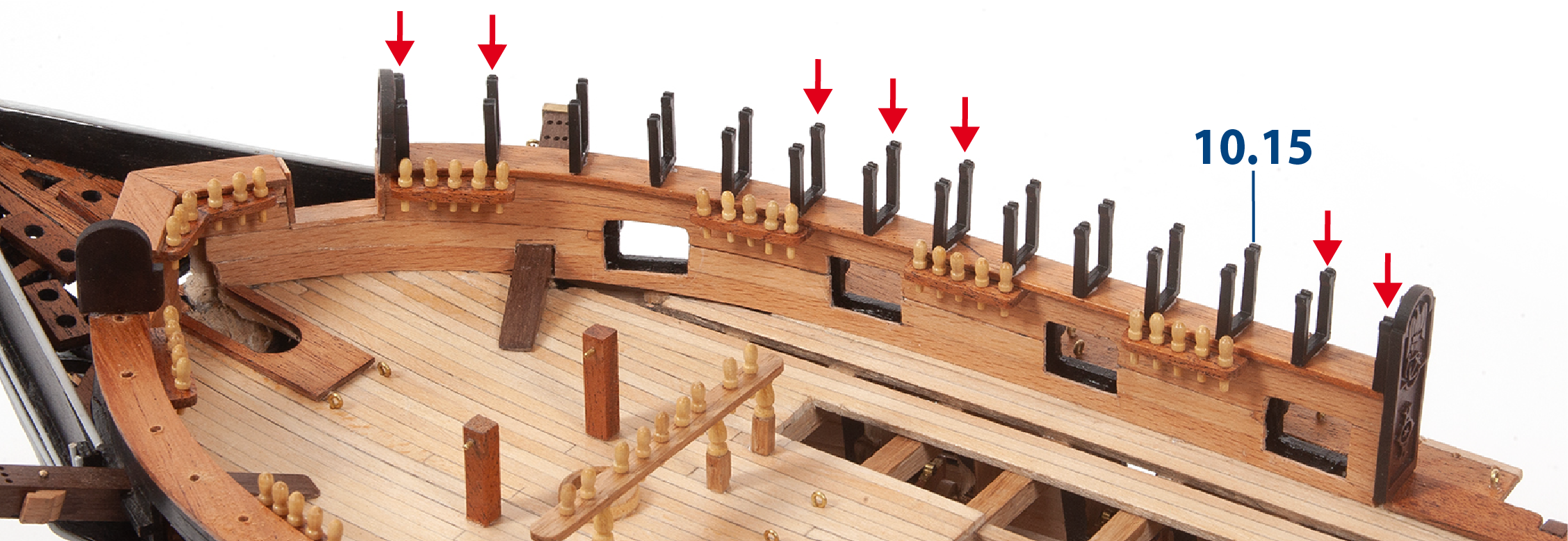
Step 1
Continue to fit and glue parts 10.15 in the bow area.
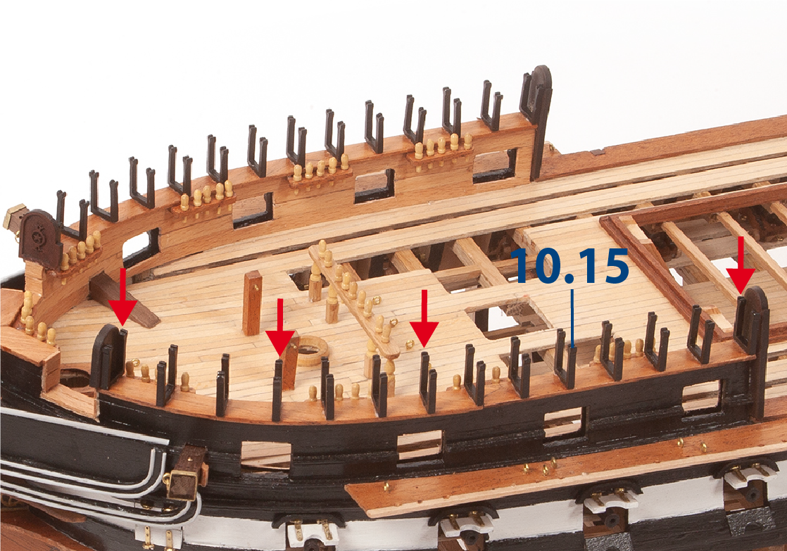
Step 2
Fit and glue parts 10.15 in the aft area.
Step 3
Glue parts 10.7 and 10.8 in the aft area.
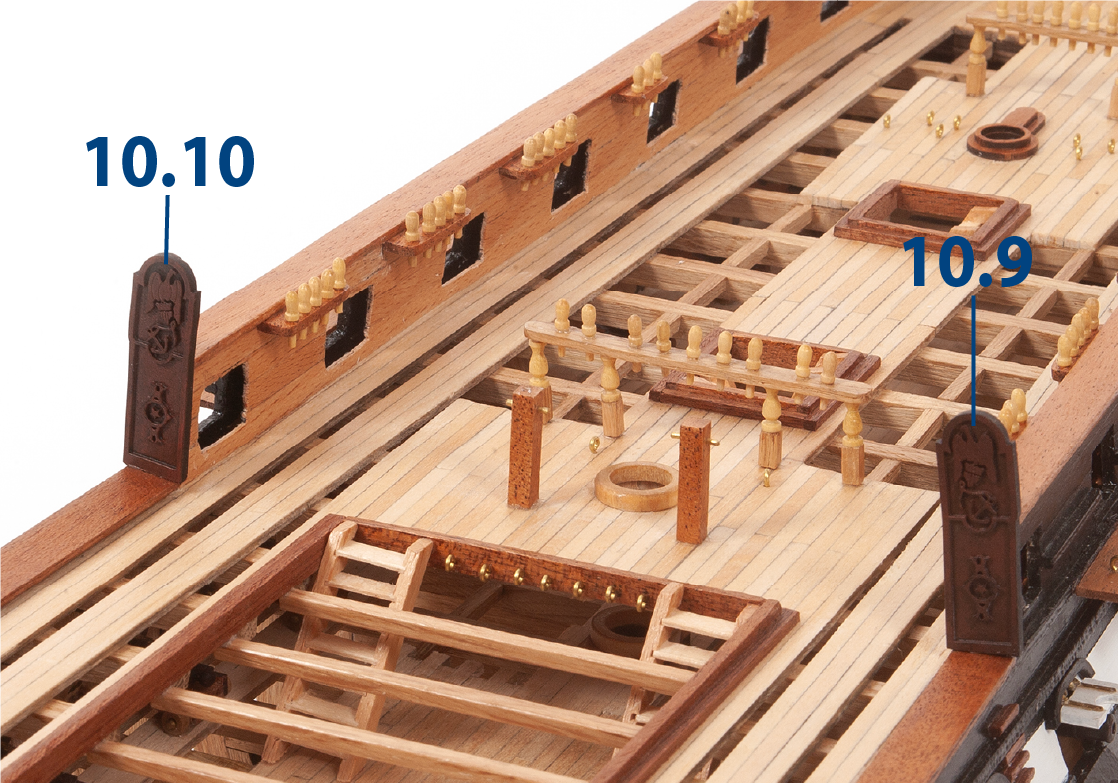
Step 4
Fit and glue parts 10.9 and 10.10 as shown.
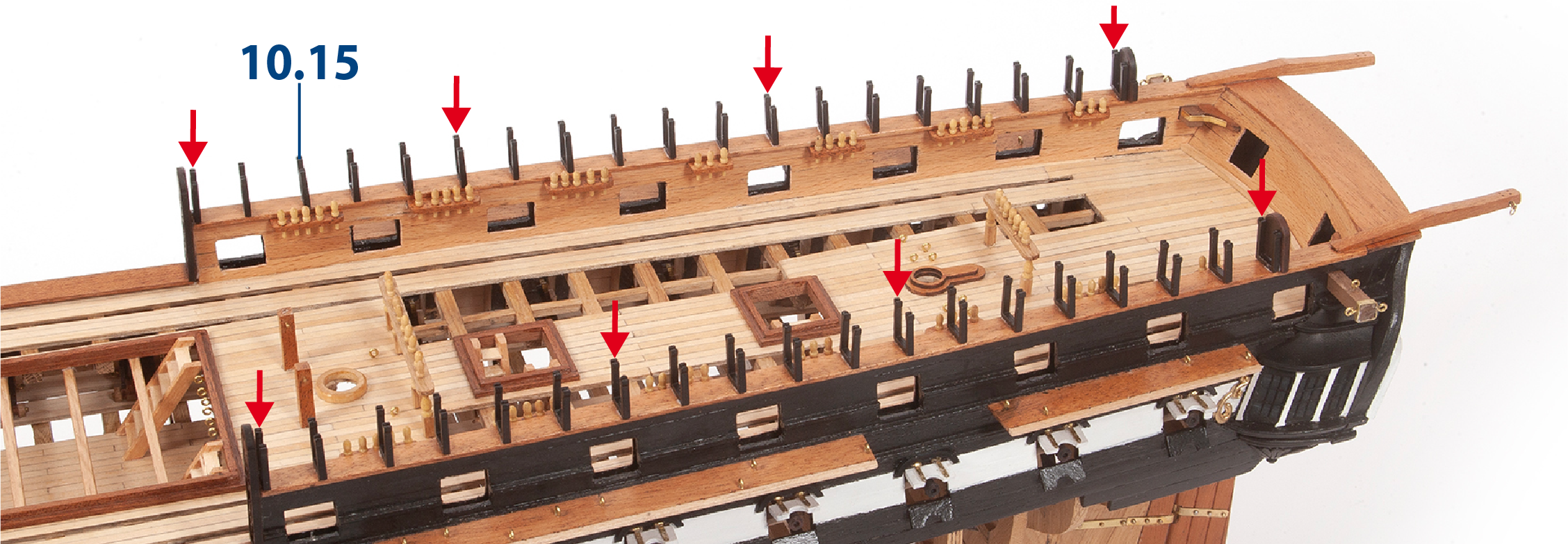
Step 5
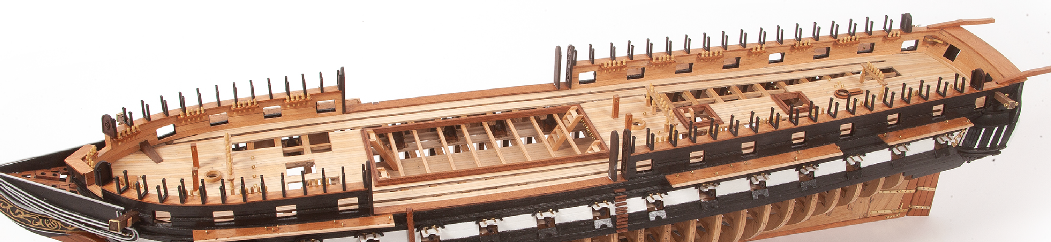
This image shows the parts fitted in place.
Step 6
Cut to size twenty parts 10.16 (ø1 x 100 mm brass), then glue the parts in place as shown.

Step 7
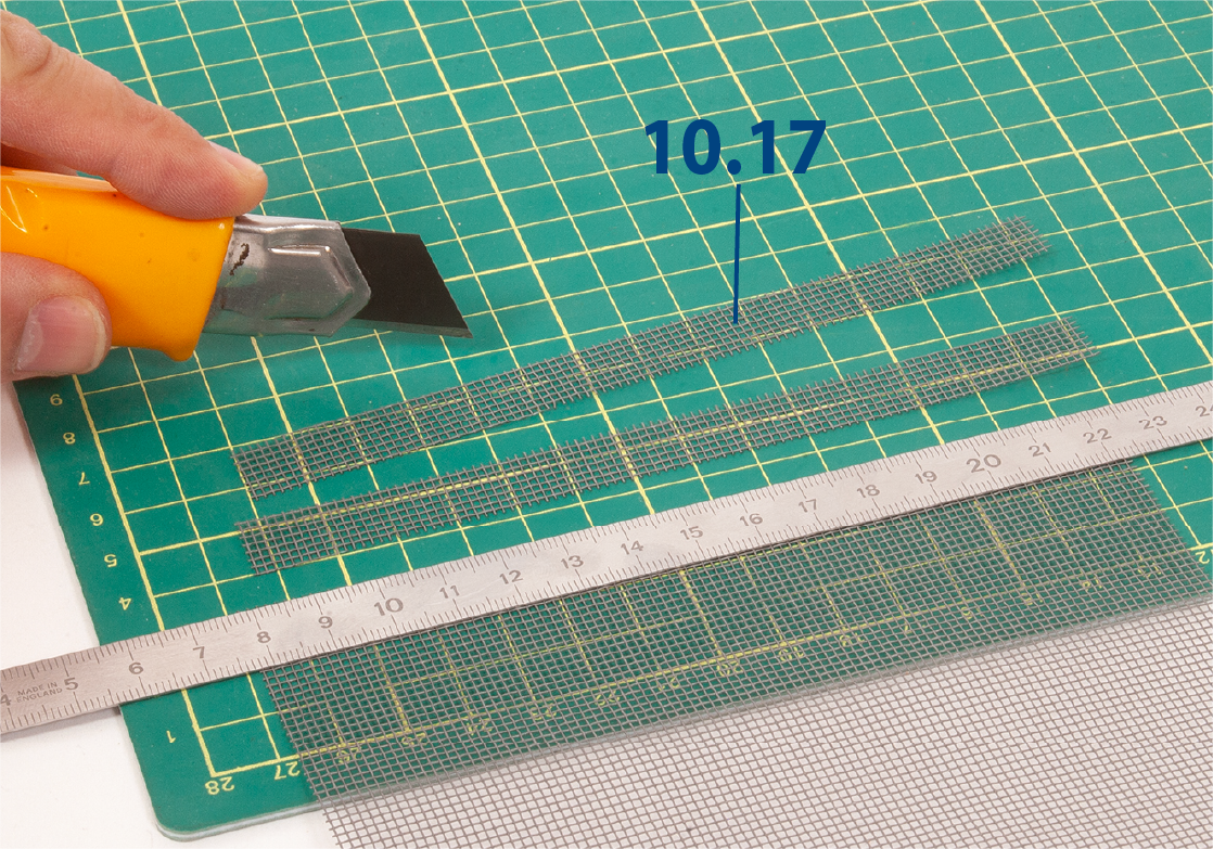
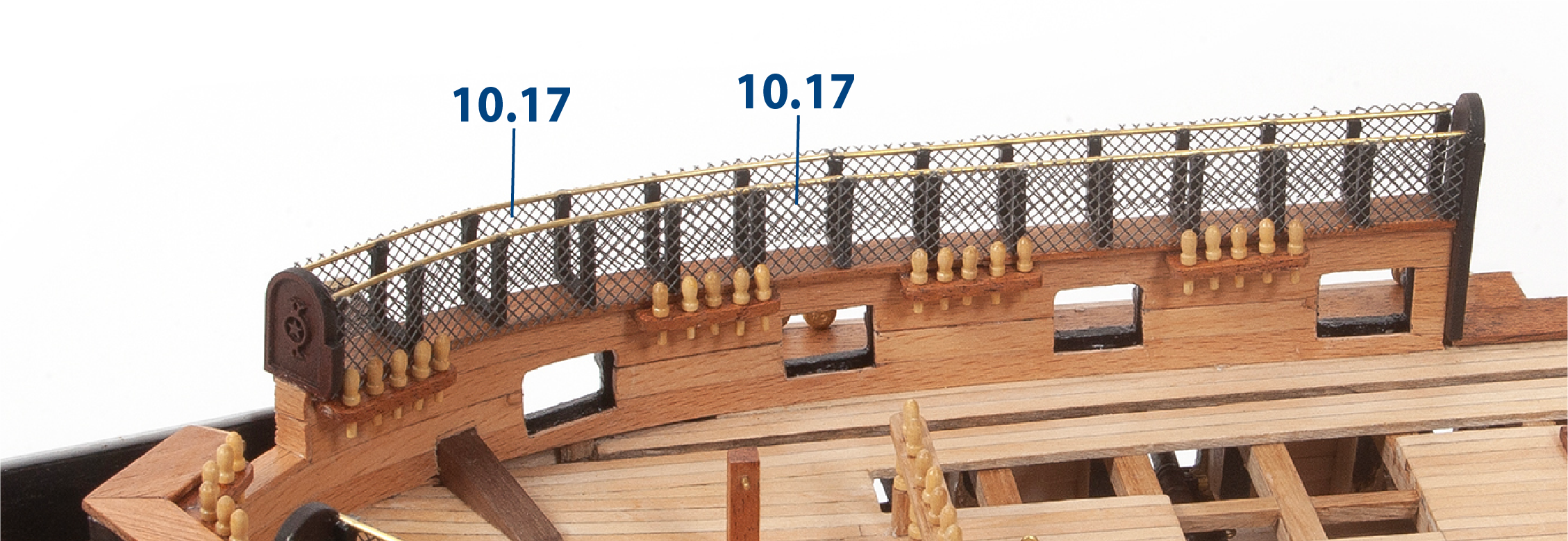
Cut twelve parts 10.17 to size (13 x 240 mm mesh). The mesh width is 200 mm, so you must join more than one piece to obtain the full 240 mm length.
Note: In steps 8, 9 and 10, the mesh is positioned so that the square openings appear in a diamond pattern. To achieve this effect , we recommend measuring directly on your model, then cutting the mesh into diagonal strips, each no larger than 13 x 100 mm. You can make up to 28 strips of this size.
Step 8
Glue the mesh strips 10.17 to the outer surfaces of parts 10.15.
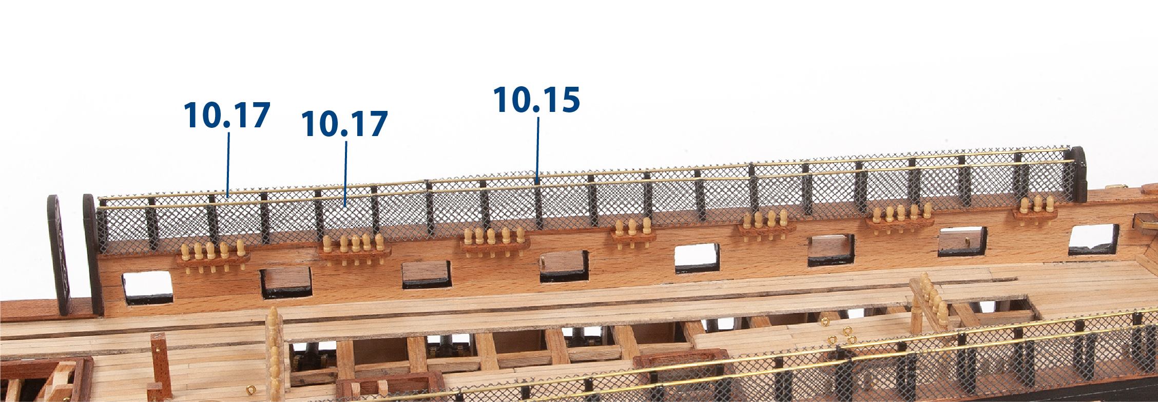
Step 9
Glue the mesh strips 10.17 in the bow area.
Step 10
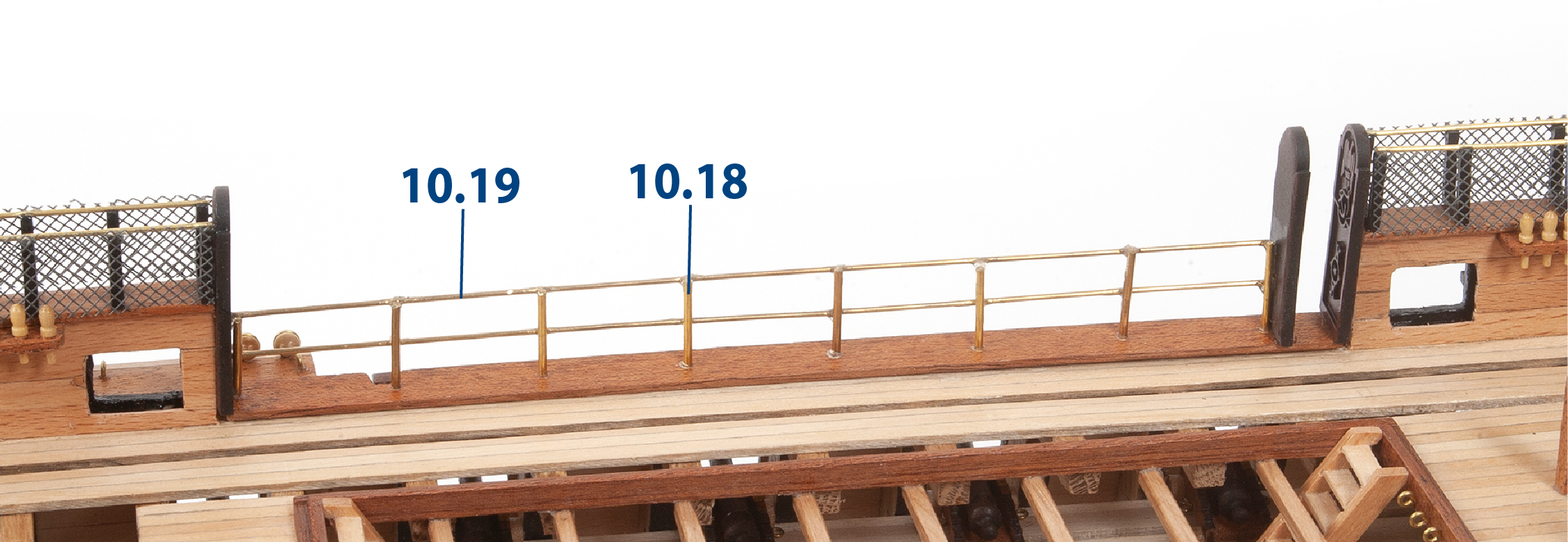
Drill holes to fit parts 10.18 (ø1.5 x 26 mm), then glue the parts in place. Fit and glue parts 10.19 (ø1 x 175 mm). Repeat this process on the opposite side of the hull, then paint the parts black once the glue has dried.
Step 1
Cut a 100 mm length of ø0.5 mm wire in half.
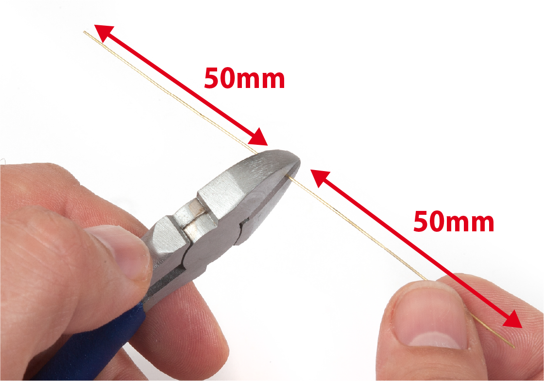
Step 2
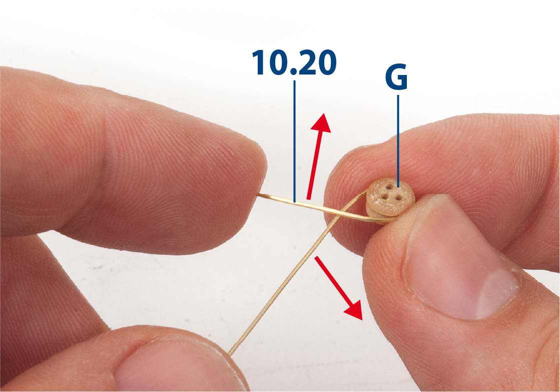
Wrap brass wire 10.20 (ø0.5 × 50 mm) around deadeye G, then cross the wire as shown.
Step 3
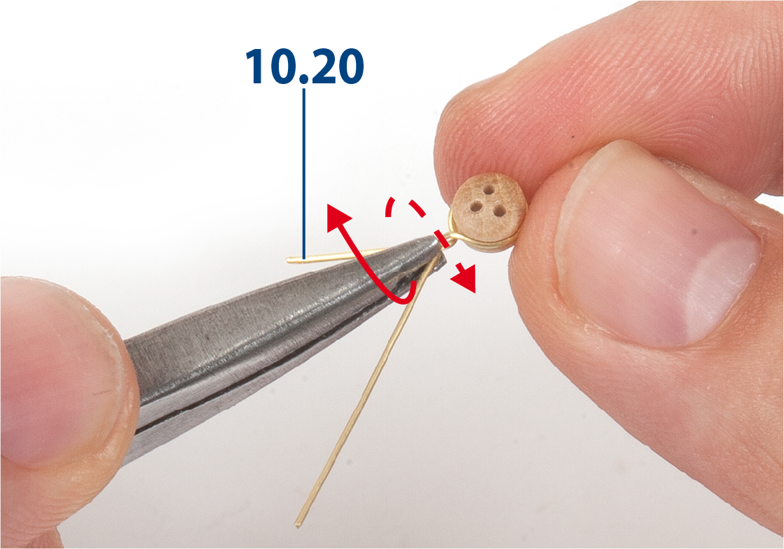
Twist the ends of part 10.20 together using pliers.
Step 4
Cut off the excess from one end then straighten the other end.

Step 5
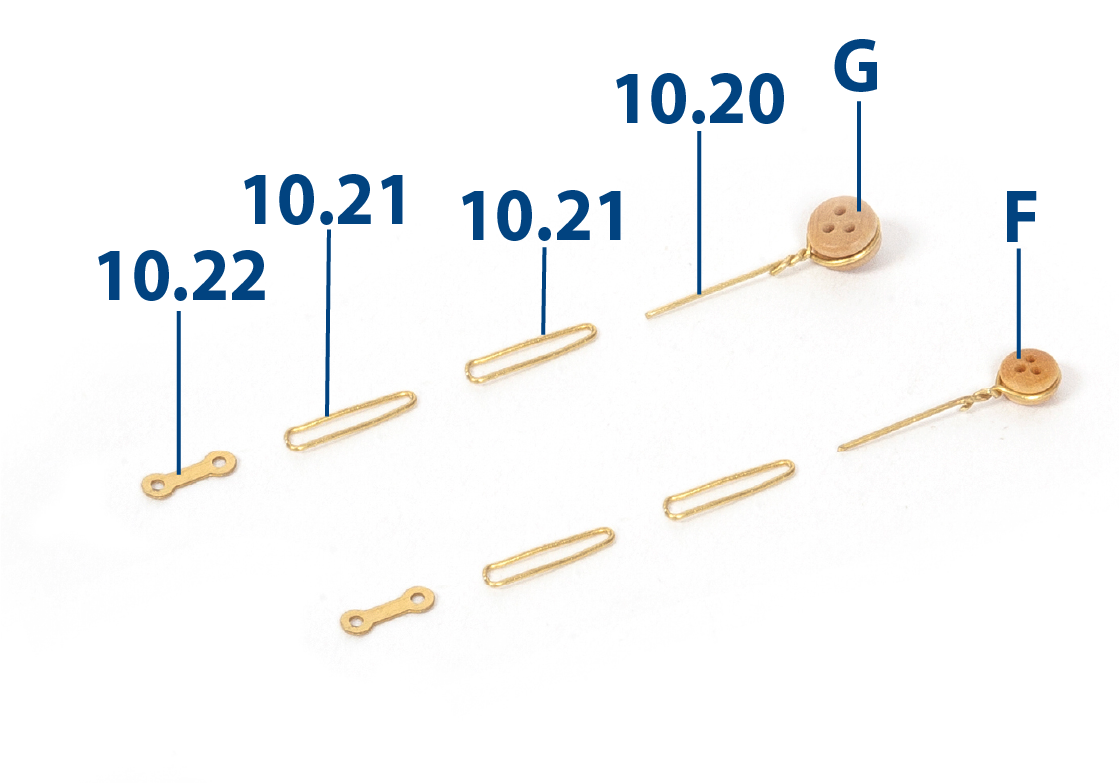
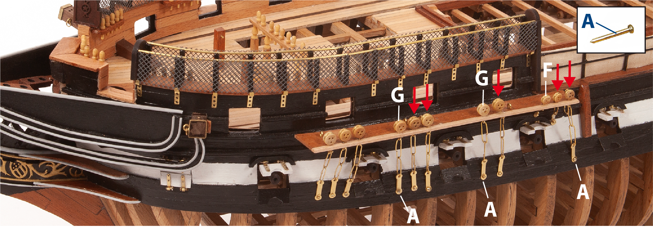
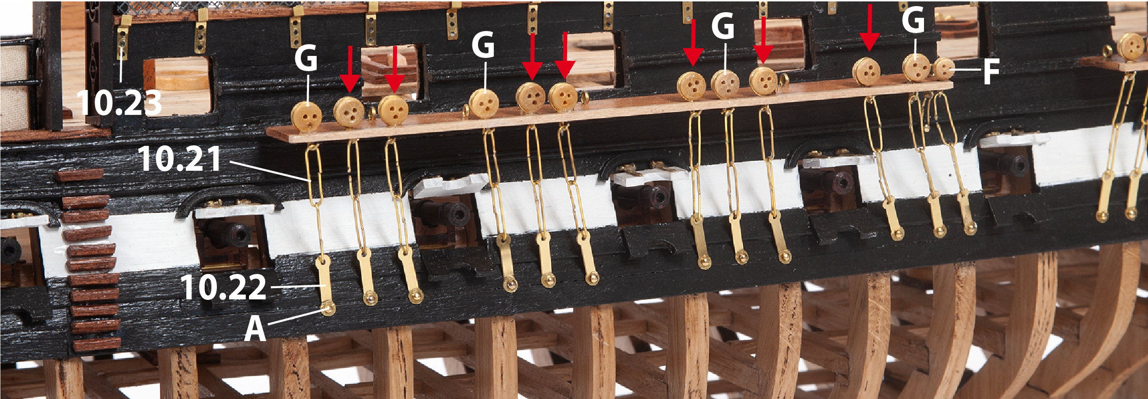
Make parts 10.21 (ø0.5 x 50 mm brass) as shown in the image. You will need to make these parts for both the small deadeyes (F) and the large deadeyes (G).
Step 6
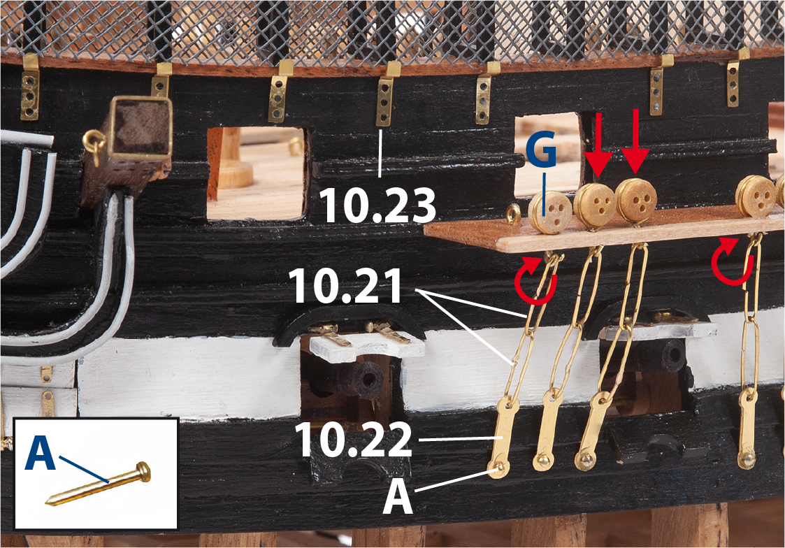
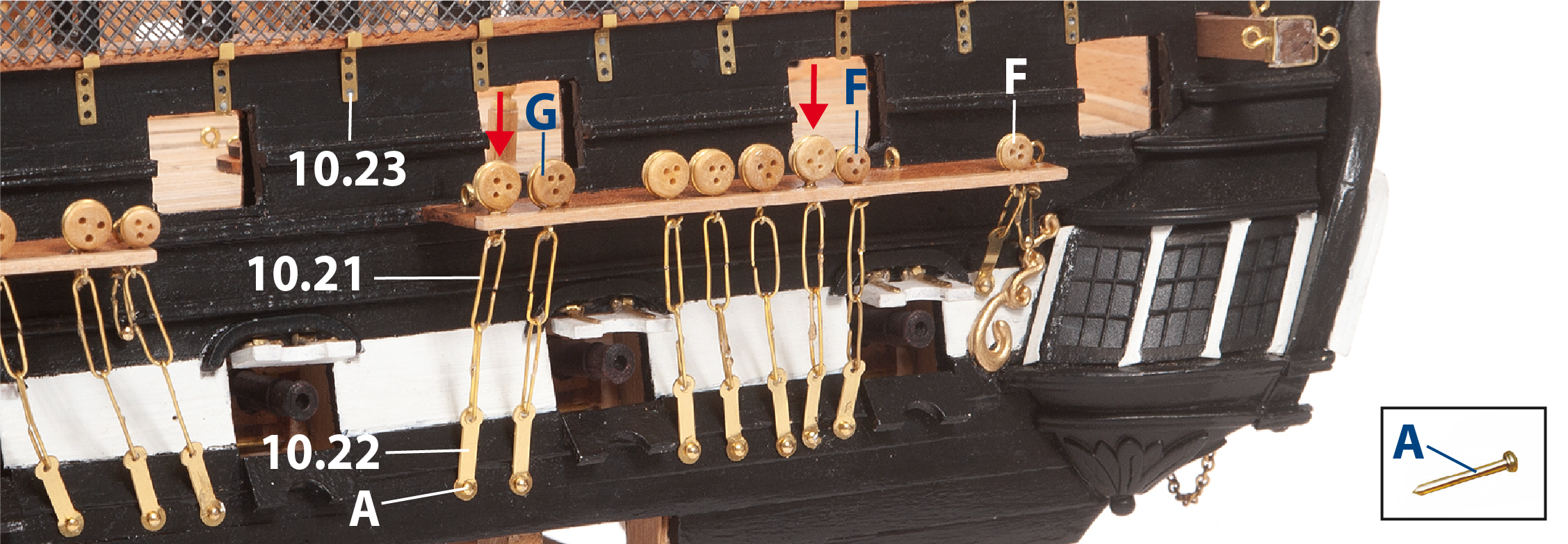
Refer to the elevation drawing and deck plan to position the deadeyes. Insert deadeyes F and G through the holes in the fore chain-wale. Curve the end of the brass wires under the chain-whale, then cut off the excess. Attach the chainplate links onto each chainplate hook. Fix the 10.22 links to the hull with nails (A).
Adjust and glue parts 10.23, aligning them as shown. Fit the parts to both the inside and the outside of the hull (see image stage 59, step 2).
Step 7
The image shows the completed fore chain-wale.
Step 8
Fit the chainplate assemblies to the main chain-wale in the same way.
Step 9
Fit the chainplate assemblies to the mizzen chain-wale in the same way. Repeat steps 6–9 on the opposite side of the hull.
Step 10
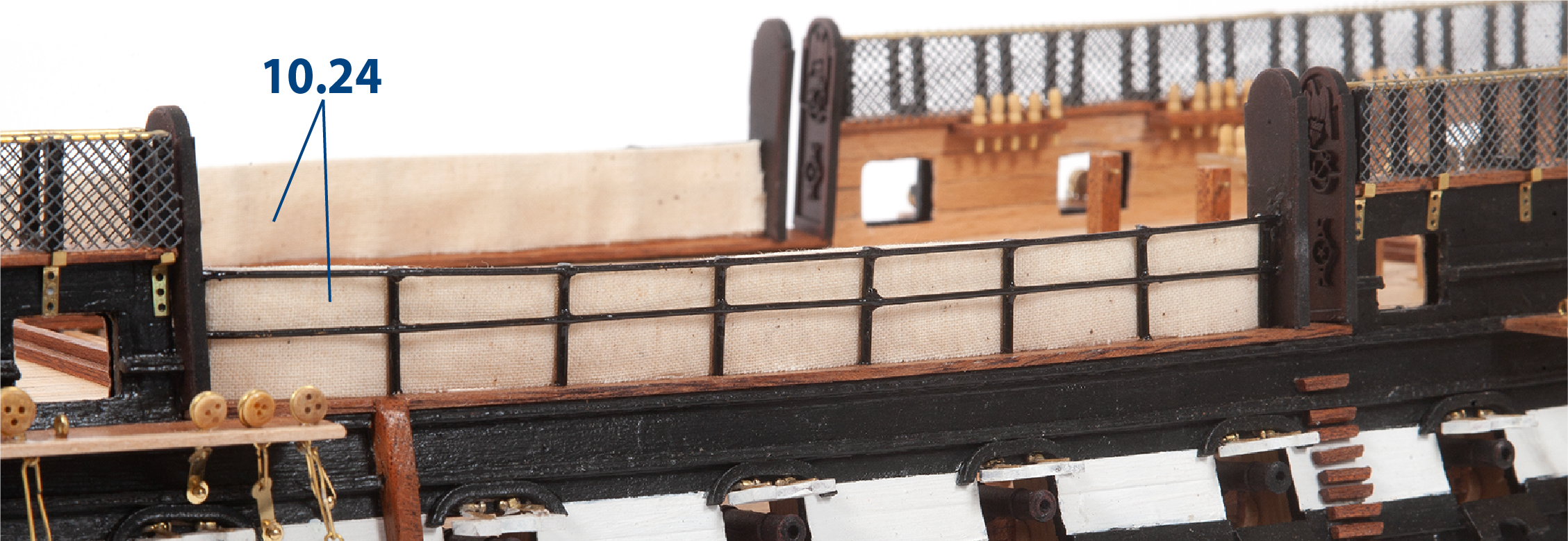
Cut two pieces of fabric 10.24 to size (40 x 170 mm). Fold each piece in half, then glue them to the inner side of the railings as shown.
Step 11
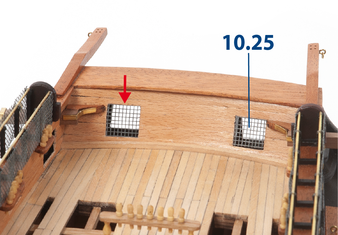
Cut two pieces of mesh 10.25 to size (10 x 10 mm), then glue them to the stern ports.
Step 1
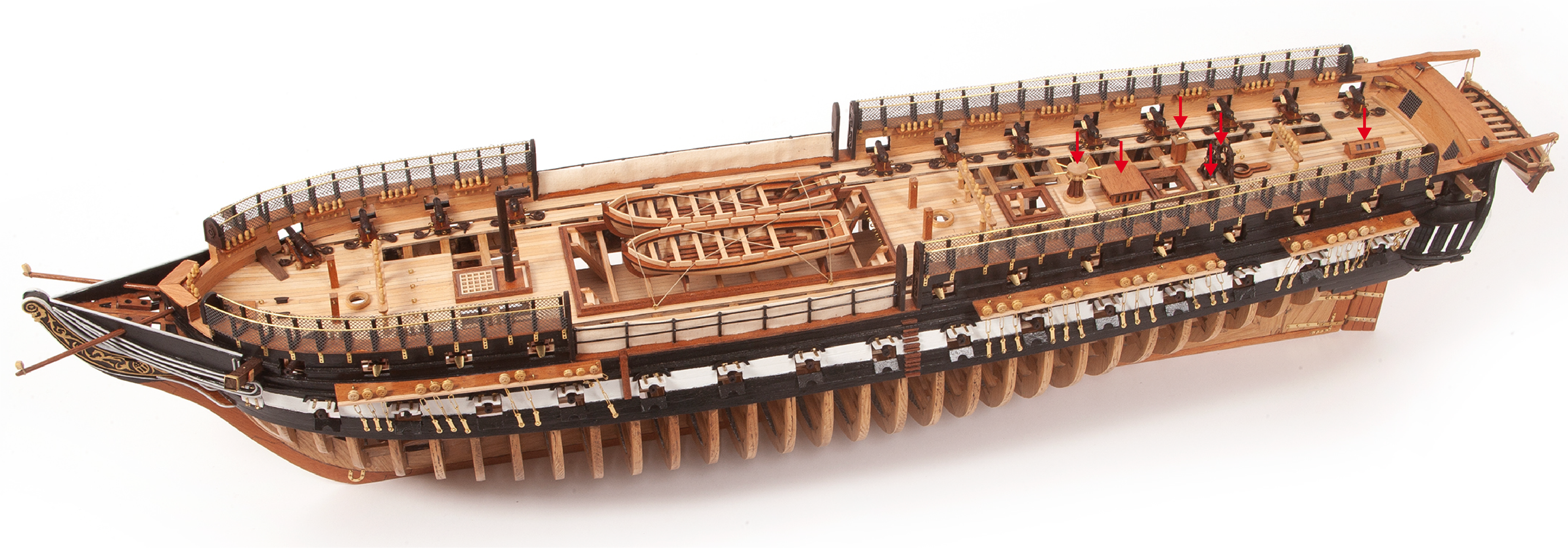
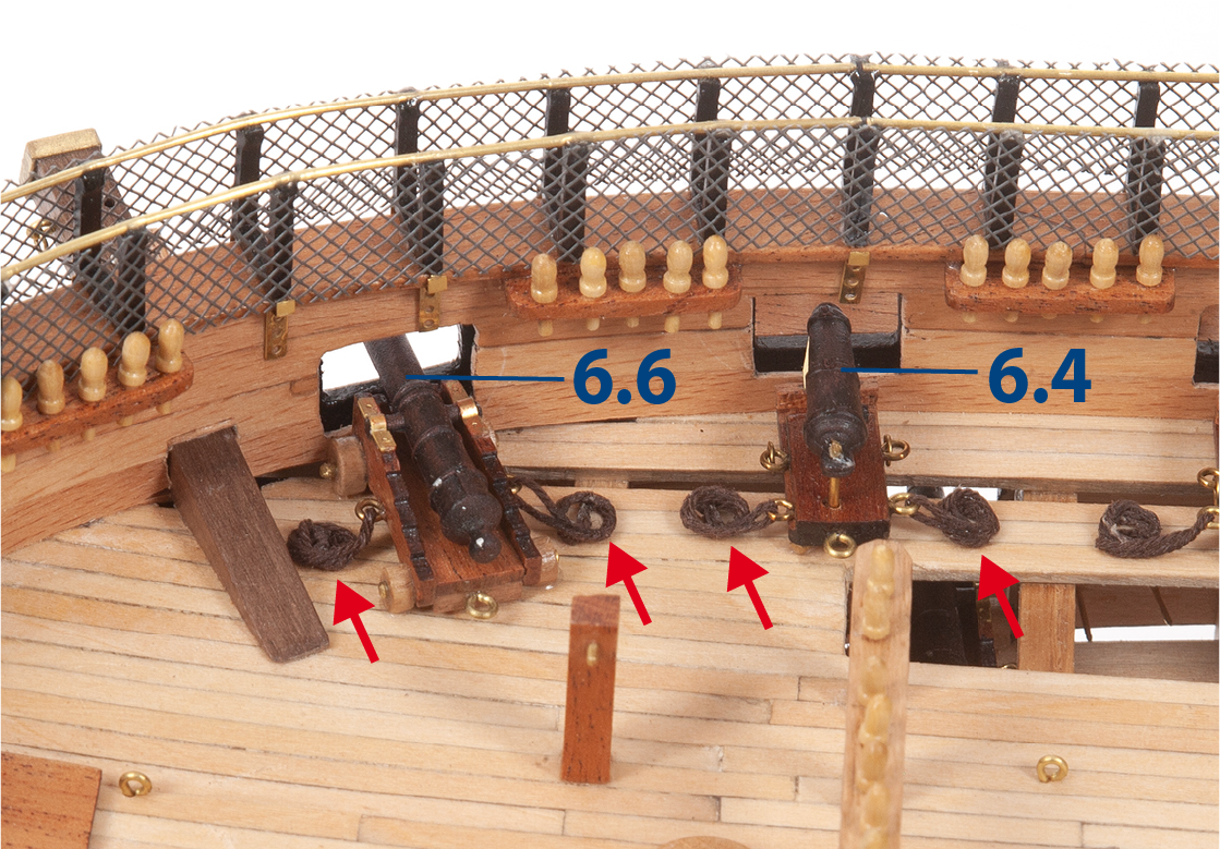
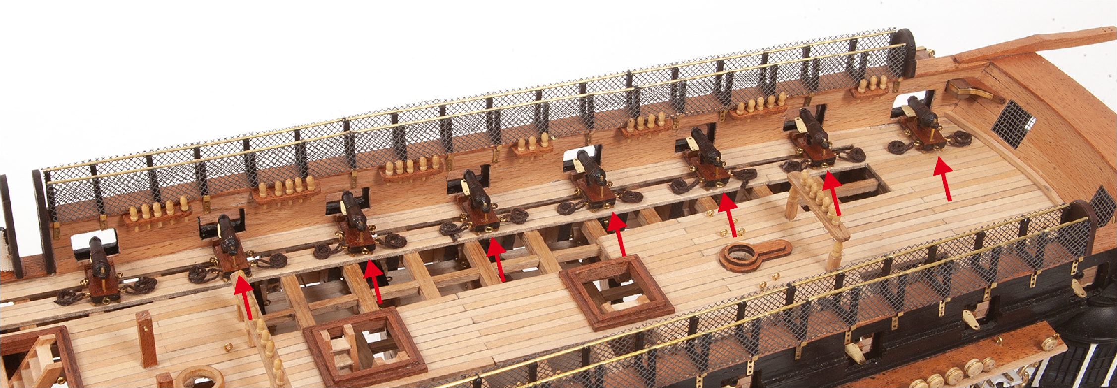
Retrieve the cannons 6.6 and carronades 6.4, then place them on the deck. Check the images below to see the guns from other angles.
Note: The carriage tackle attached to the gun carriages in this image and the following ones (red arrows) is made using ø0.5 mm brown thread, which will be supplied in pack 11. Do not use the brown thread supplied in this pack.
Please wait until you have attached the brown thread from pack 11 before gluing the cannons and carronades.
Step 2
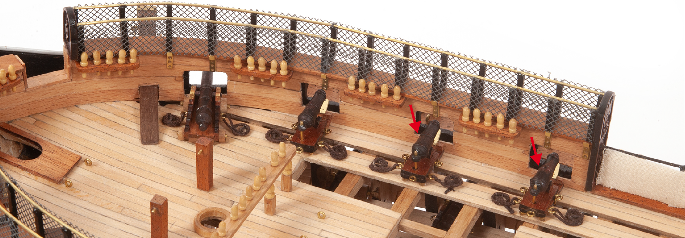
Continue to place the guns in the bow area as shown.
Step 3
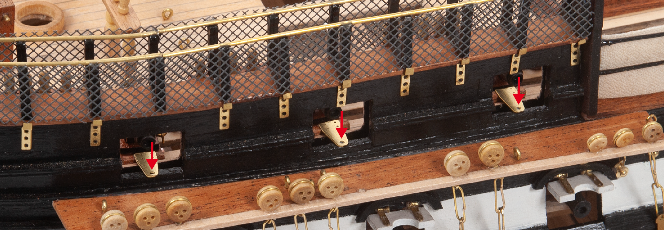
This image shows how the carronades are held in place in the gunports.
Step 4
Continue to place all the guns on both sides of the ship.
Step 5
Glue the chimney assembly from Stage 46 to the deck. Then, glue parts 10.27 (2 x 2 x 22 mm mahogany) and parts 10.28 (2 x 2 x 43 mm mahogany) to make the frame.
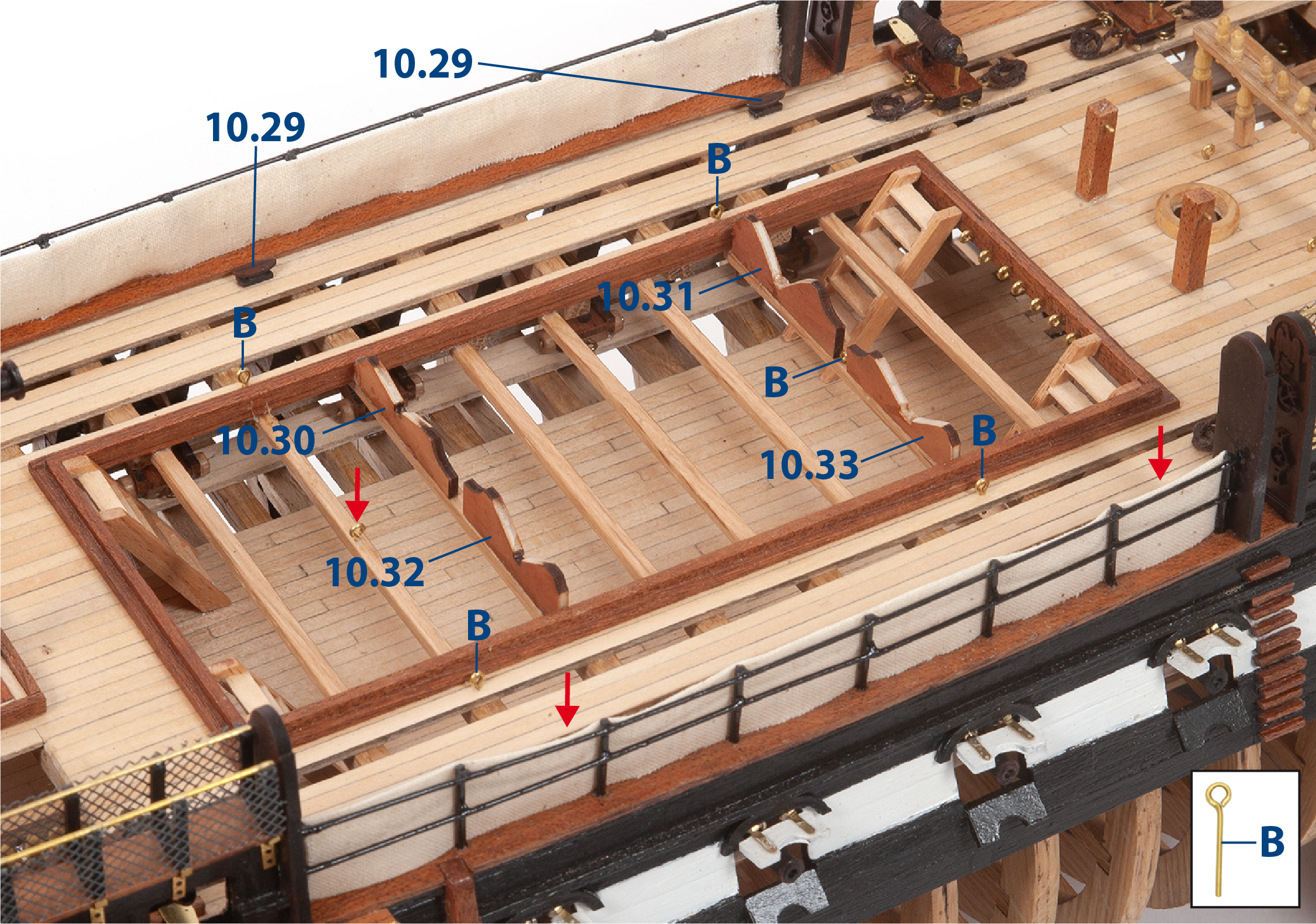
Paint parts 10.29 (small cleats, pack 9) black and drybrush them with red paint. Once the paint is dry, glue the cleats in place as shown on the deck plan.

Step 1
Fit and glue the parts shown in the picture. Adjust the parts so they support the two larger boats A and B (see Step 3).
Step 2
Cut to length thread 10.34 (ø0.15 x 500 mm). The image shows the route of the thread to secure the boats in step 3.
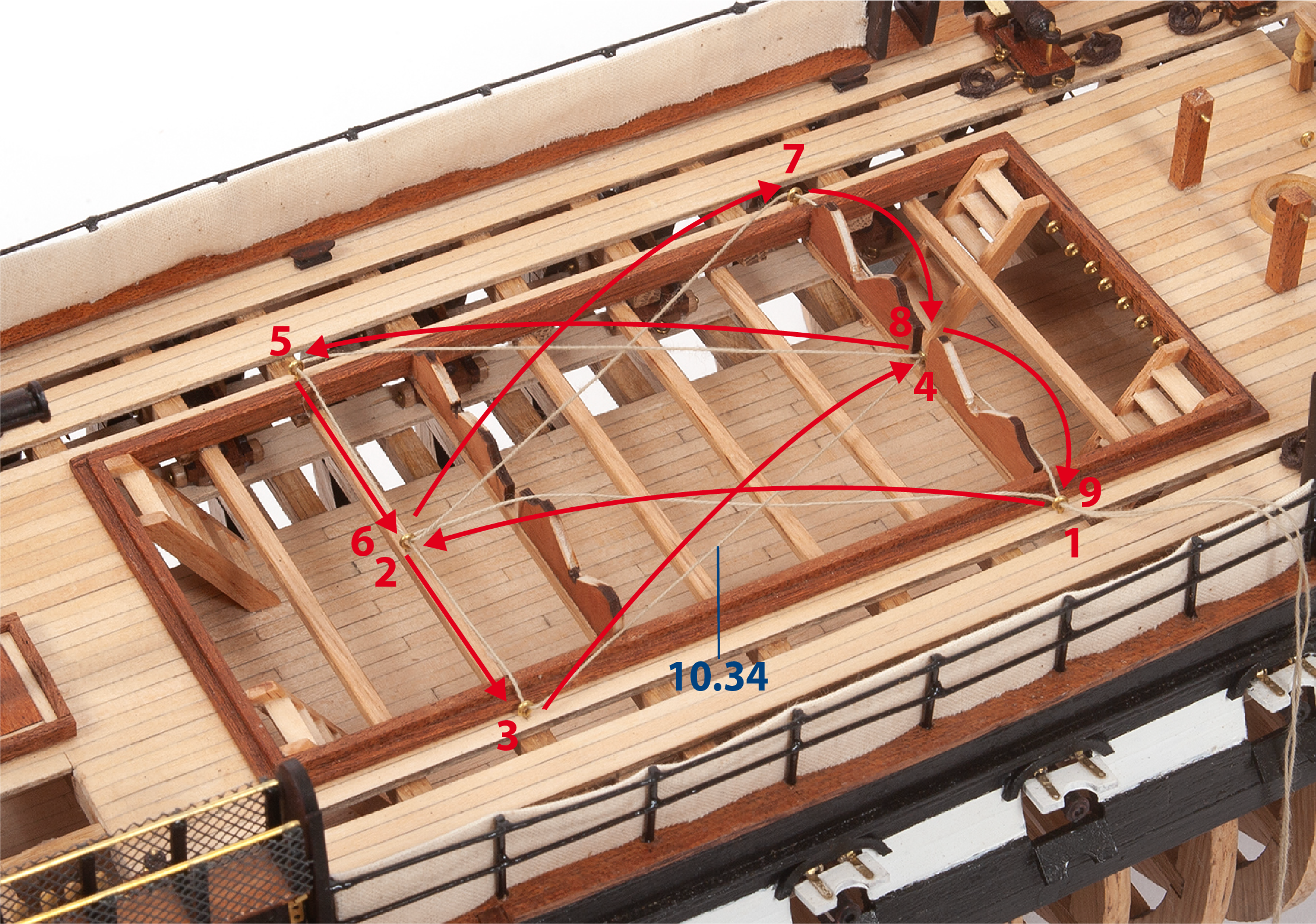
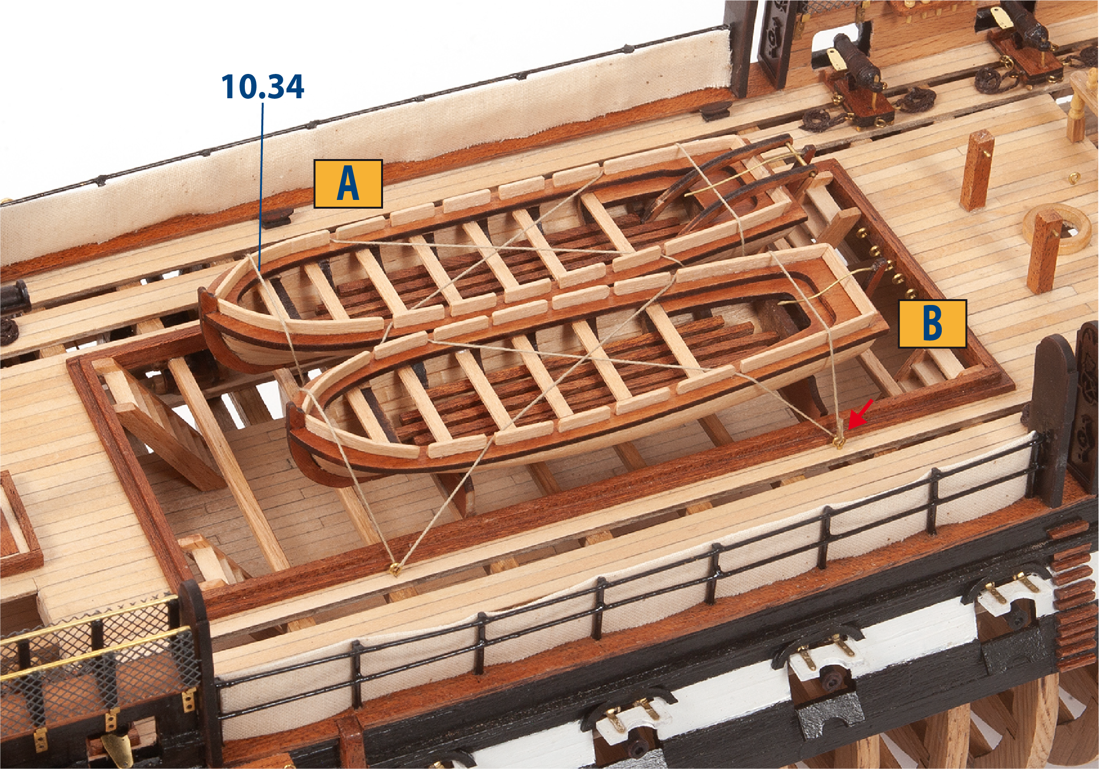
Step 3
Place boats A and B on their supports and secure them using thread 10.34. Tie the thread to the eyebolt indicated by the red arrow, then cut off any excess.
Step 4
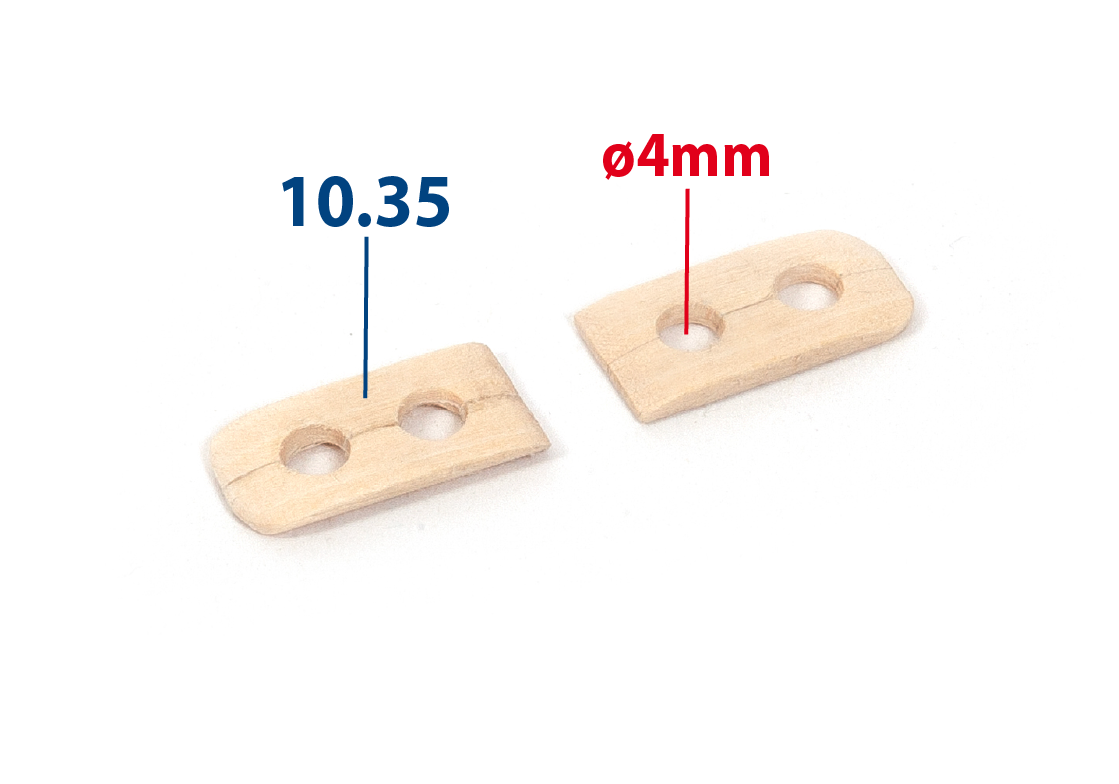
Make parts 10.35 (2 x 5 x 20 mm lime wood) and drill ø4 mm holes as shown, then paint the parts black.
Step 5
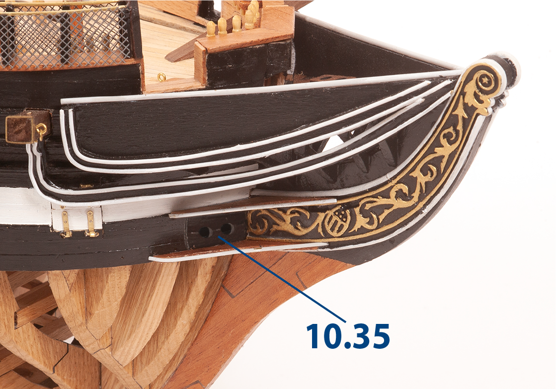
Glue parts 10.35 as shown on both sides of the hull.
Step 6
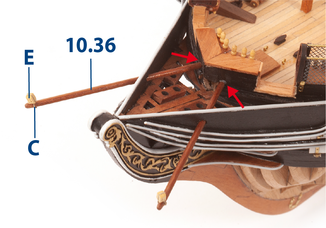
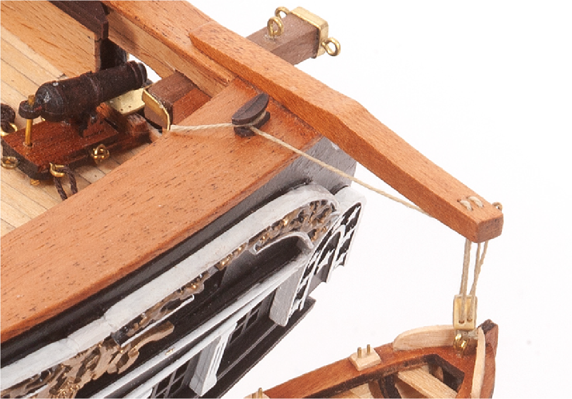
Drill the holes needed to insert parts 10.36 (ø3 x 85 mm mahogany, supplied in pack 8) into the bow of the ship. Attach blocks E (pack 7 and 9) to parts 10.36 using thread C (ø0.15 mm).
Step 7
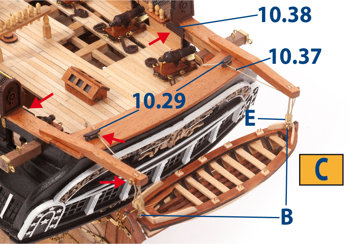
Fit eyebolts B and blocks E to boat C as shown in the image.
Cut thread 10.37 (ø0.15 x 250 mm) to length and tie one end to the eyebolt on the davit ring. Pass the other end of the thread through the first hole in block E and pull it up to the davit. Pass the thread through all the holes in block E and the davits, then wrap the end of the thread around the cleat 10.29. Repeat this process for the davit on the opposite side.
Paint black, then glue parts 10.38 (large cleat, pack 9) as shown.
Step 8
Using the deck plan, fit and glue the helm wheel (pack 8), the binnacles (pack 8), the capstan (pack 9), and the skylights (pack 9) to the deck. The image shows how the model should look after the parts are fitted.
To age the wood, first test Judea Bitumen on a scrap piece. Apply a very thin layer to the varnished wood and, if necessary, soften the effect by wiping gently with a damp cloth.