Pack 6
BUILD INSTRUCTIONS
Instructions for building your USS Constitution model ship
Your model of the USS Constitution is divided into 12 packs.
You will need to follow the step-by-step assembly photos, the plans and the explanatory texts below.
Please save the leftover materials from each pack for use when instructed to do so at a later stage of the assembly instructions.
The IP sheets displayed below are drawings of laser-cut parts and photo-etched brass parts and will serve as a guide for identification of some parts.
Use the PARTS REFERENCE table to help locate the parts.
The PL-00 templates (printed at 1/1 scale) included in each pack will serve as a guide for building the model.
Please check the list below to ensure you have all the tools required for building your wooden ship.
When removing a part, cut the ribs that join the part to the wooden plate with a cutter.
Remove the parts carefully so as not to break them.
Keep and store the parts in their frames. Only remove the parts you are working on in each step.
Extra support can be found on our forum or from the Expert Directory page of our website.
PARTS LIST
| Material | Quantity | |
| Boards 2001-24 – 2001-27 | Wood | 4 |
| Wooden Strips | ||
| 2 x 3 x 600 mm | Lime wood | 20 |
| 1 x 5 x 600 mm | Lime wood | 10 |
| 6 x 6 x 600 mm | African walnut | 1 |
| 2 x 2 x 600 mm | Lime wood | 10 |
| 2 x 5 x 600 mm | Mahogany | 60 |
| Other Parts | ||
| Cannon barrels | 15 | |
| Cannon barrels (short) | 2 | |
| Wire (ø1.5 x 100 mm) | Brass | 10 |
| Wire (ø1 x 100 mm) | Brass | 25 |
| Carronade barrels | 22 | |
| Carronade swivel | 25 | |
| Wood block 4 mm | 75 | |
| Grating | 96 | |
| Reinforcement 2 x 100 mm | Brass | 5 |
| Cleat | 5 |
Tools you will need: cutting mat, pencil, cutting knife, fine-grit sandpaper or sponge sandpaper, file, white wood glue, super glue (cyanoacrylate glue), masking tape, set square, hacksaw, sanding block, 30 cm steel ruler, clamps, drill, moulding scriber tool
PACK 06 IDENTIFICATION SHEETS
PARTS REFERENCE
PART NO. | IP-SHEET LOCATION | PART NO. | IP-SHEET LOCATION | PART NO. | IP-SHEET LOCATION |
| 6.7 | 2001-37 | 6.19 | 2001-24 | 6.27 | 2001-14 |
| 6.8 | 2001-37 | 6.20 | 2001-24 | 6.28 | 2001-24 |
| 6.11 | 2001-38 | 6.21 | 2001-24 | 6.29 | 2001-24 |
| 6.12 | 2001-37 | 6.22 | 2001-24 | 6.45 | 2001-26 |
| 6.14 | 2001-25 | 6.23 | 2001-24 | 6.46 | 2001-26 |
| 6.15 | 2001-25 | 6.24 | 2001-24 | 6.47 | 2001-26 |
| 6.16 | 2001-25 | 6.25 | 2001-24 | 6.48 | 2001-26 |
| 6.18 | 2001-24 | 6.26 | 2001-14 | 6.49 | 2001-27 |
Step 1
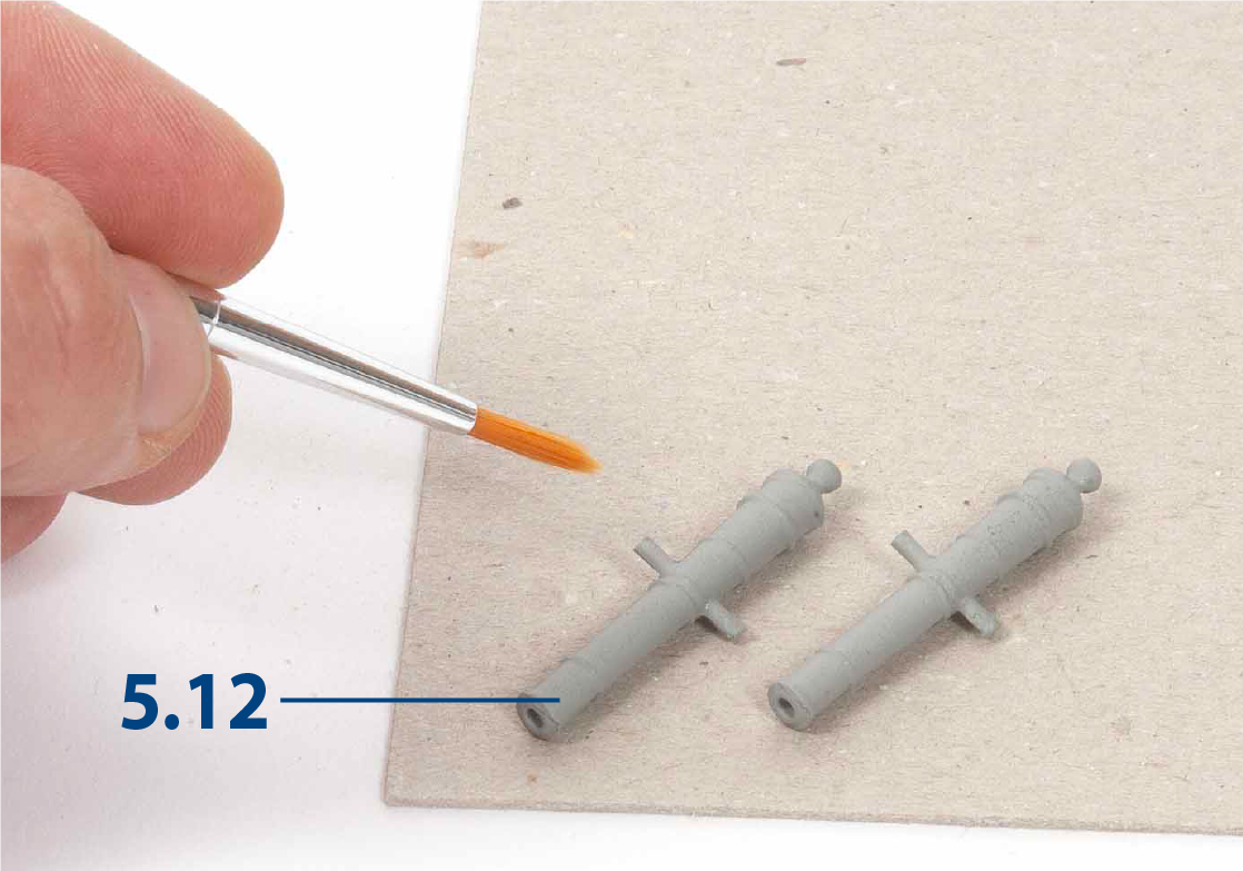
You'll now build the next 15 cannons. If you do not like the colour of the barrels, you can paint them. First apply primer.
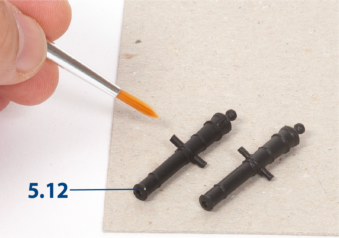
Step 2
Paint the barrels black.
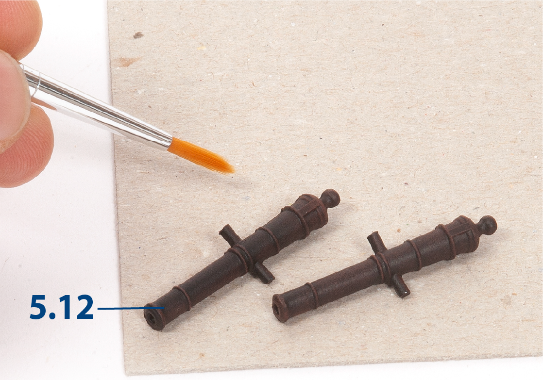
Step 3
Use the dry brush technique to highlight the reliefs of the barrels with red paint.
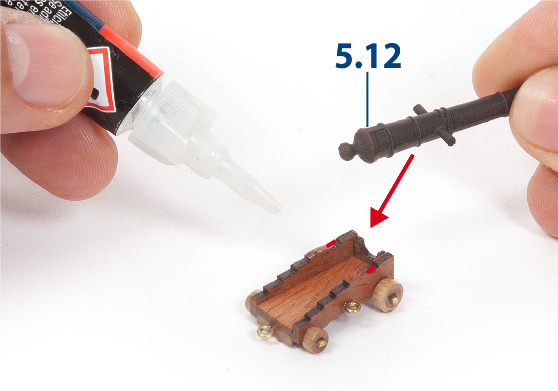
Step 4
Apply glue and fix the barrels on the gun carriages.
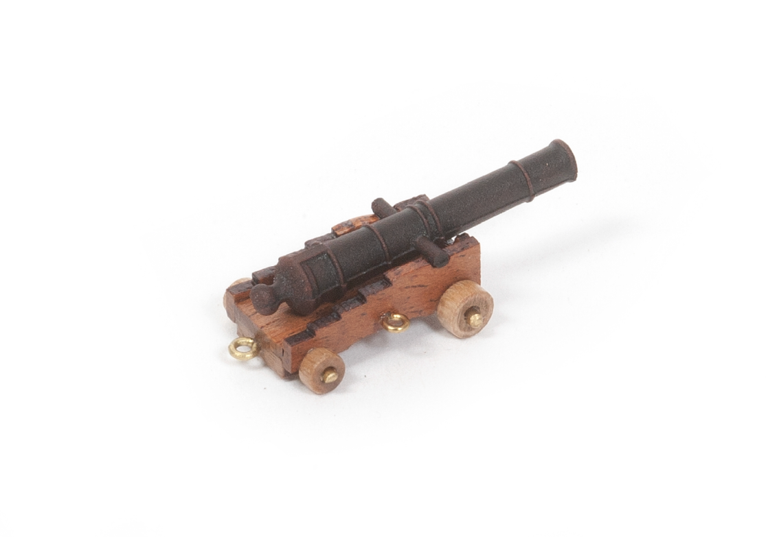
Step 5
This is what the barrel will look like on the gun carriage.
Step 6
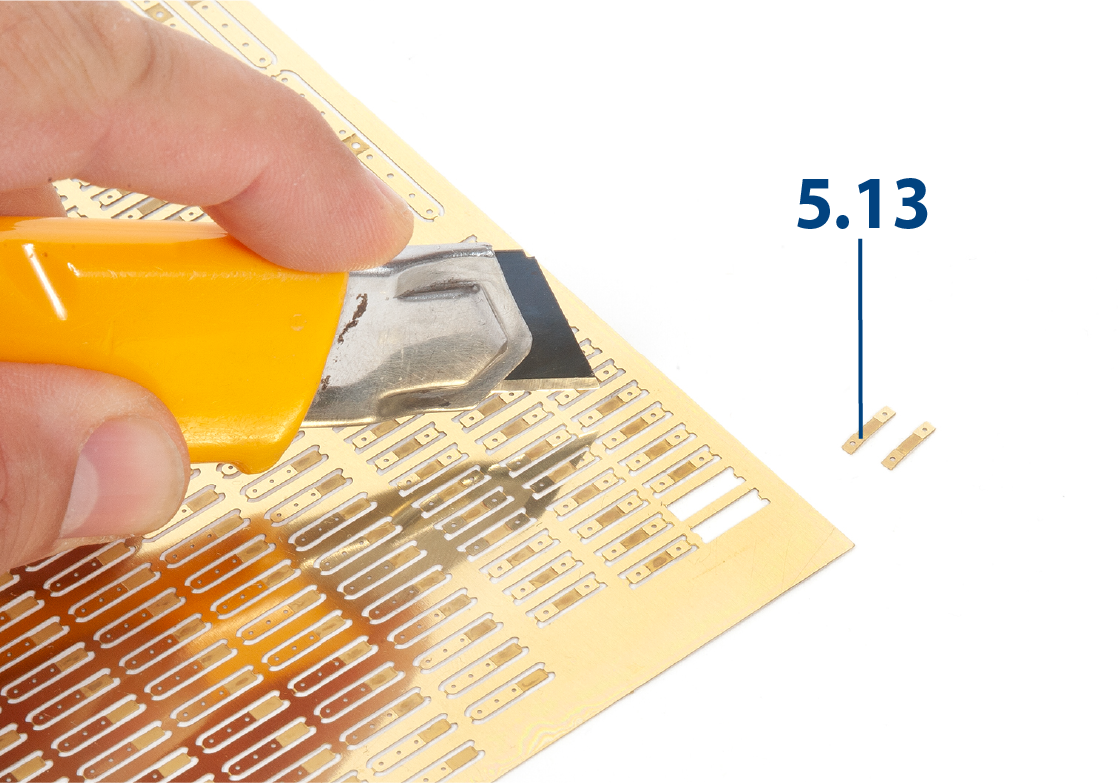
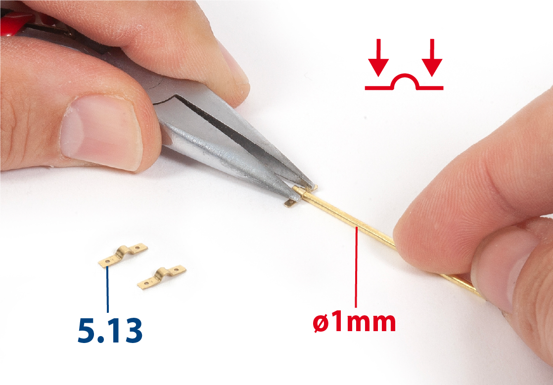
Remove the parts 5.13 from the brass sheet.
Step 7
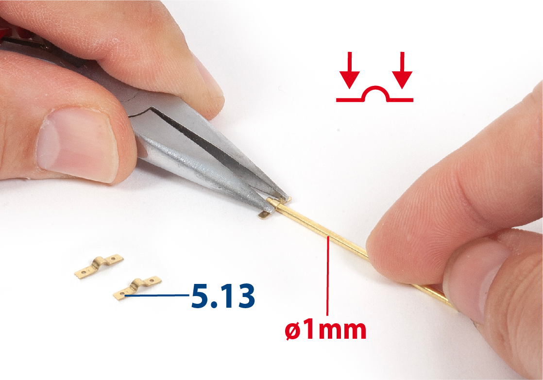
Use a brass wire and flat pliers to shape the parts 5.13.
Step 8
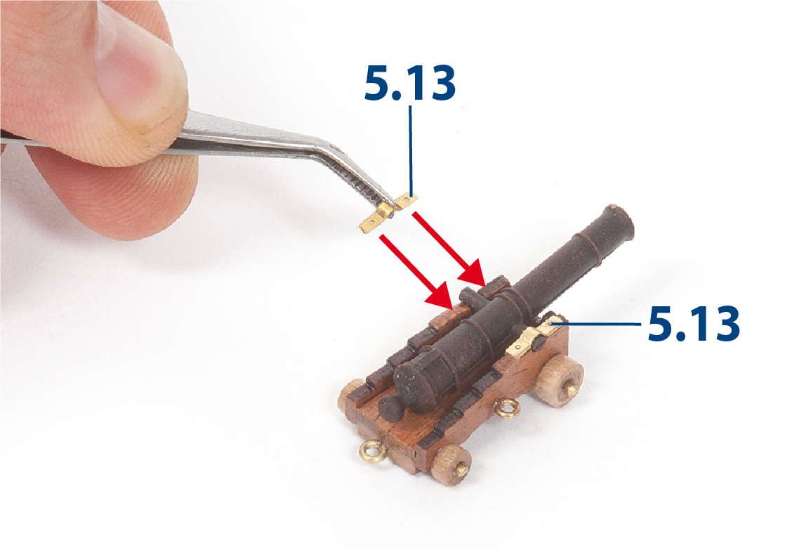
Apply glue and fix the parts 5.13 on the barrel shafts.
Step 9
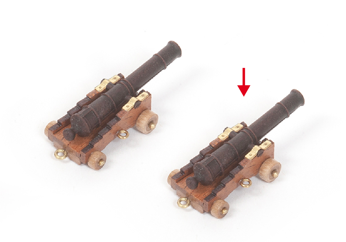
With these cannons and the ones you built earlier, you should have 30 complete units.
Step 10
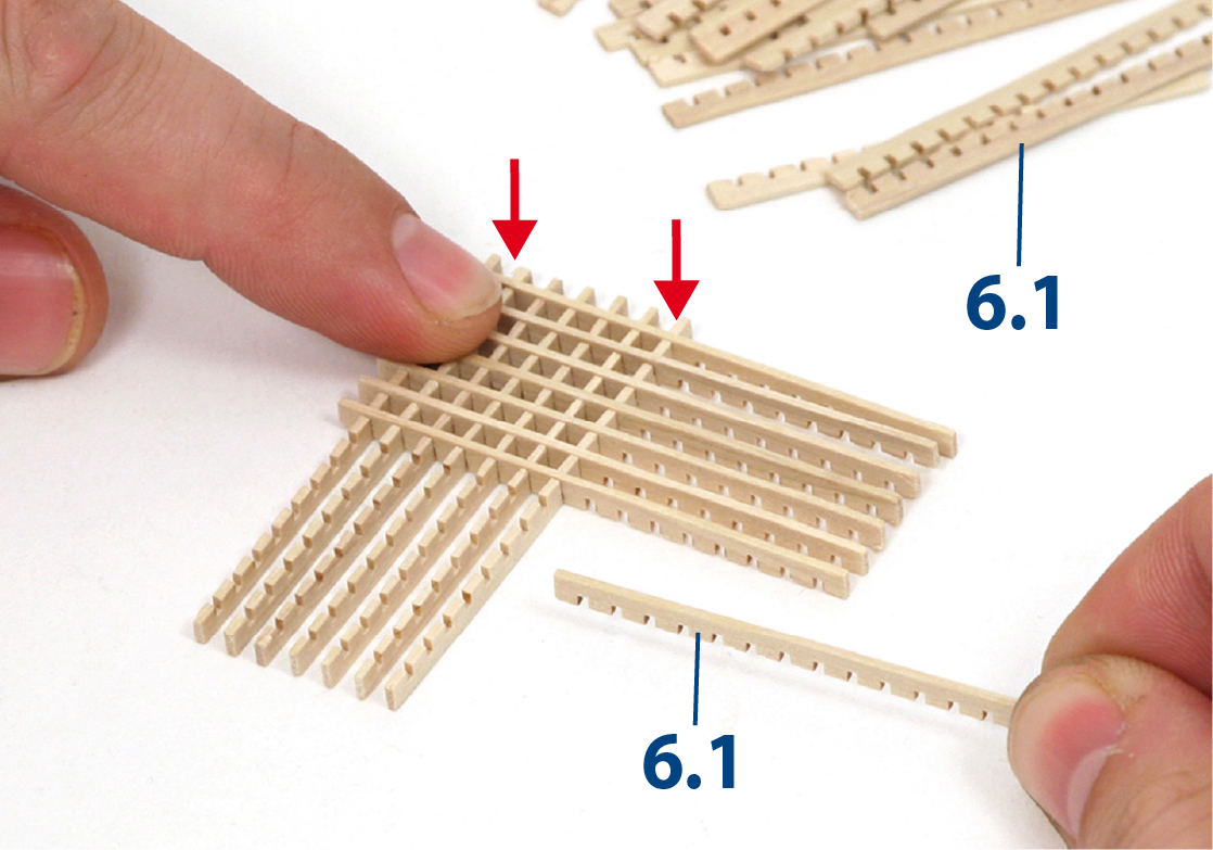
Lay pieces 6.1 in a criss-cross pattern to build up the grating.
Step 11
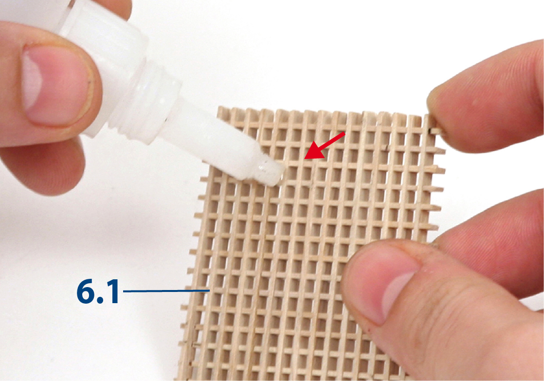
You will need to build a complete grid. Reinforce the intersecting points with quick-drying glue.
Step 12
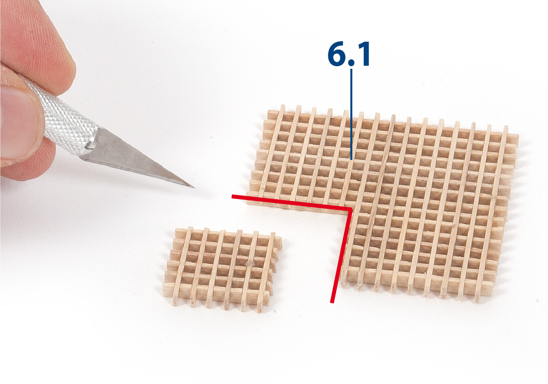
Count the holes in the part so that you can cut it accurately. Remove the part shown in the picture.
Step 13
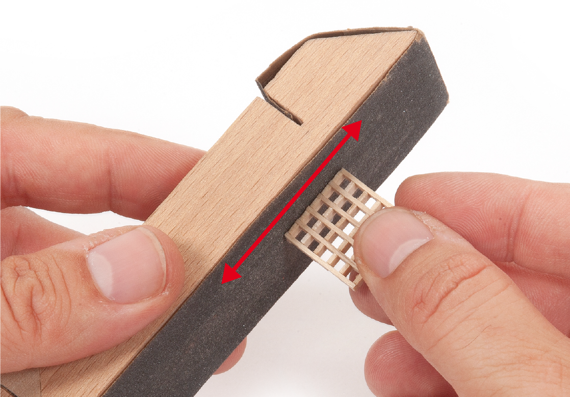
Use a sanding block to smooth the sides of the piece.
Step 14
Cut to length parts 6.2 (18 mm) and 6.3 (22 mm) from 2 x 3 mm strips (supplied with pack 4).
Step 15
Glue the aligned pieces together as shown in the picture. Sand the sides to smooth them.
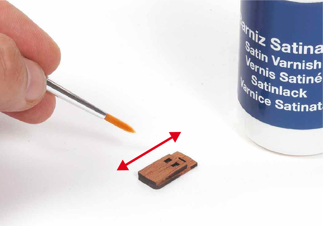
Step 16
Varnish the parts.
Step 1
Glue parts 6.5 to parts 6.4.
Step 2
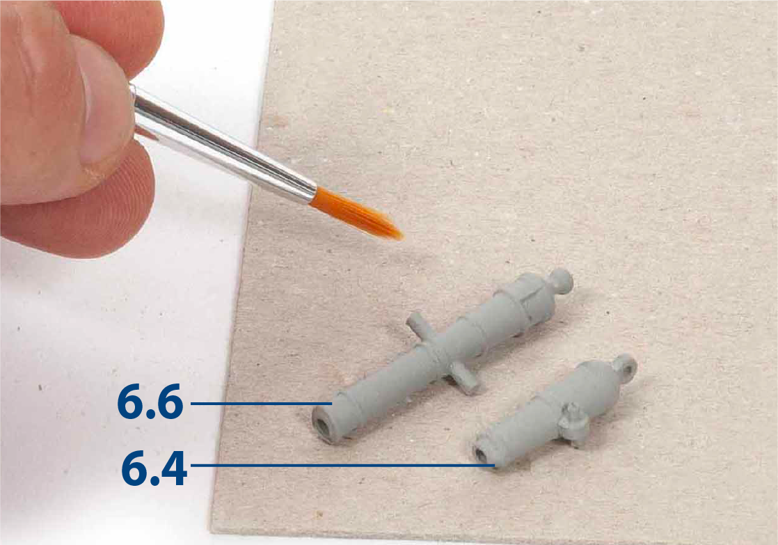
If you wish to paint the 6.4 and 6.6 barrels, prime them first.
Step 3
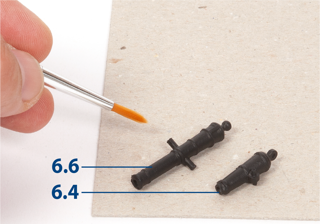
Then paint them black.
Step 4
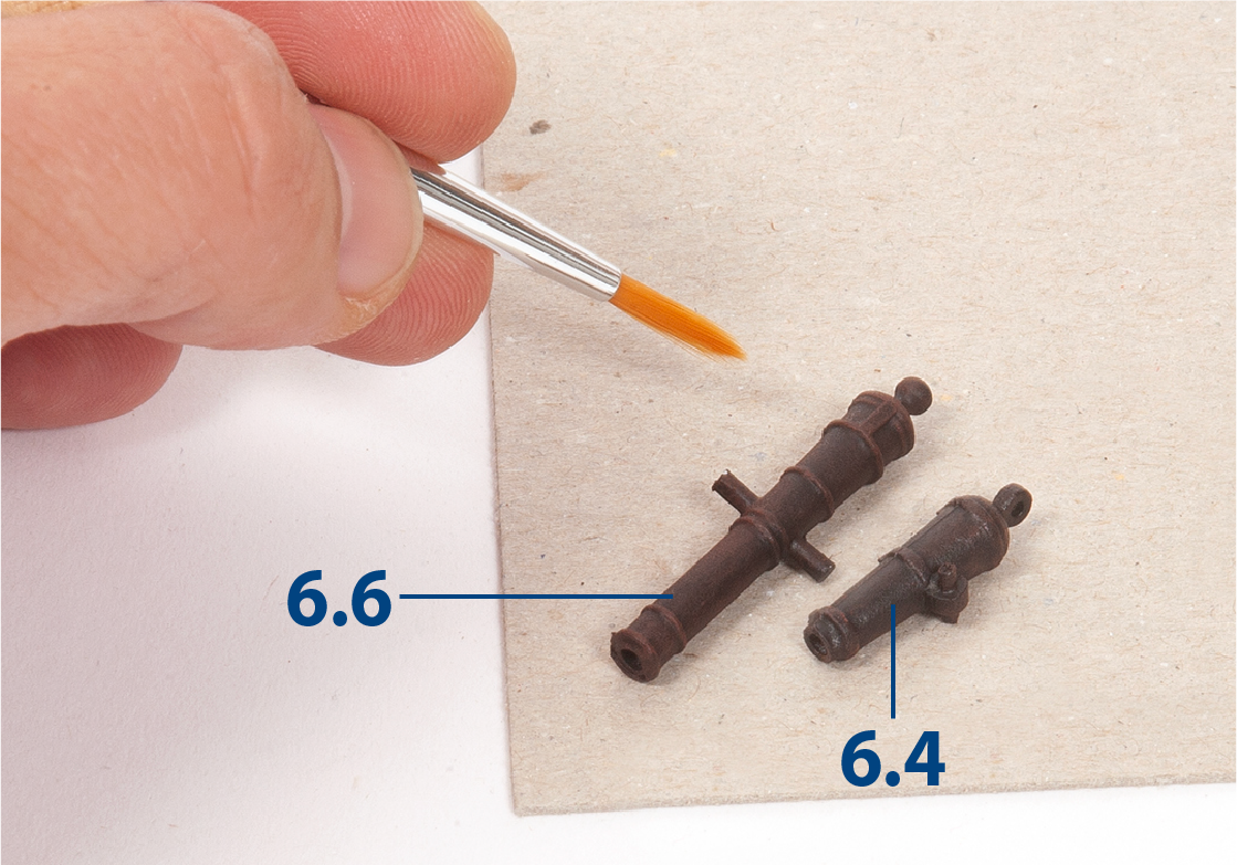
Drybrush the reliefs with red paint.
Step 5
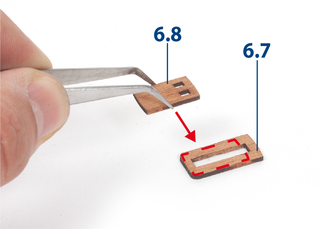
Sand parts 6.7 and 6.8 (supplied in pack 5) and glue them together as shown.
Step 6
You should make 7 identical sets. Apply varnish.
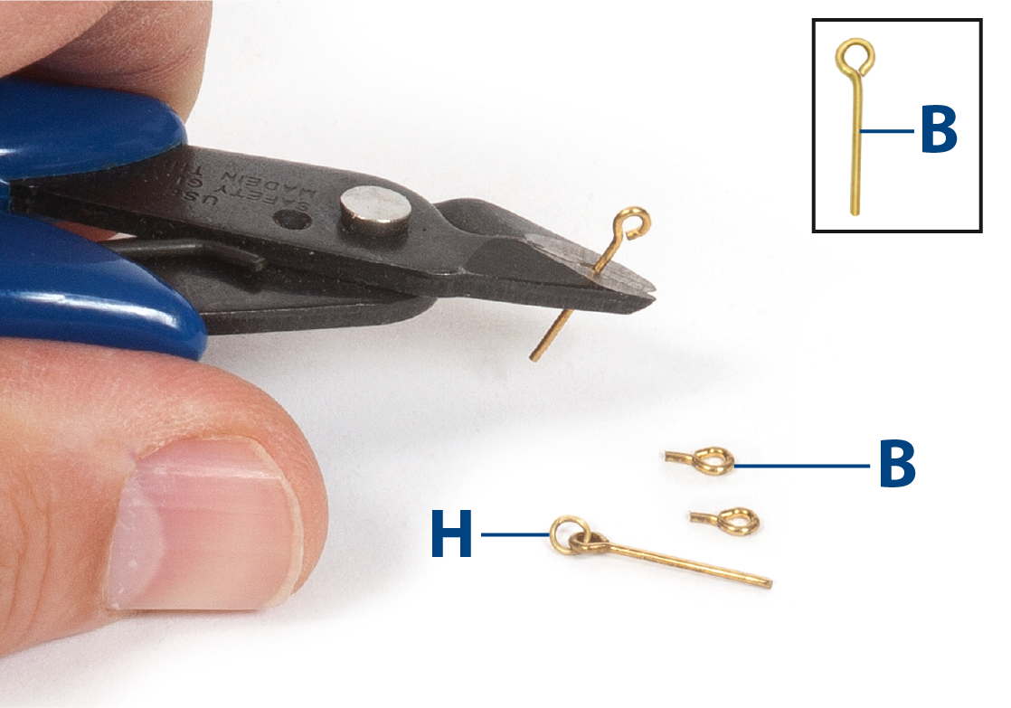
Step 7
Use pliers to open the eyebolts B and rings H (supplied in pack 5), link them together, then close them and cut the excess of the eyebolts.
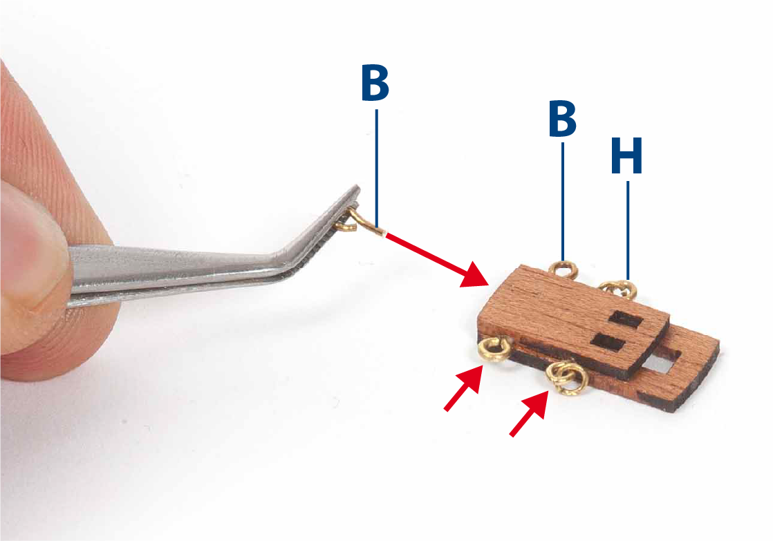
Step 8
Drill holes in the carronade bases and insert and glue the parts shown in the picture.
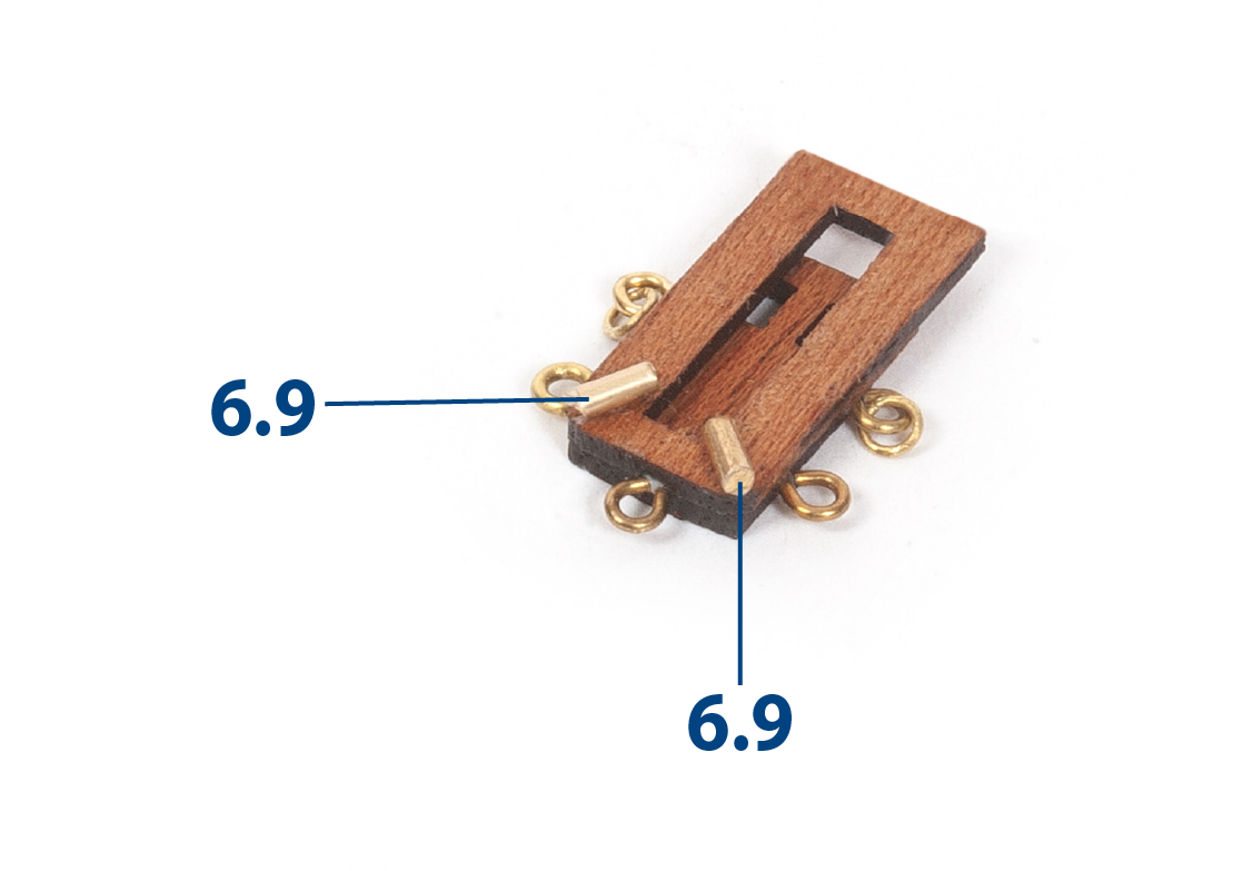
Step 9
Cut to length and glue parts 6.9 (ø 1.5 x 4 mm) to the bottom of the carronade bases.
Step 10
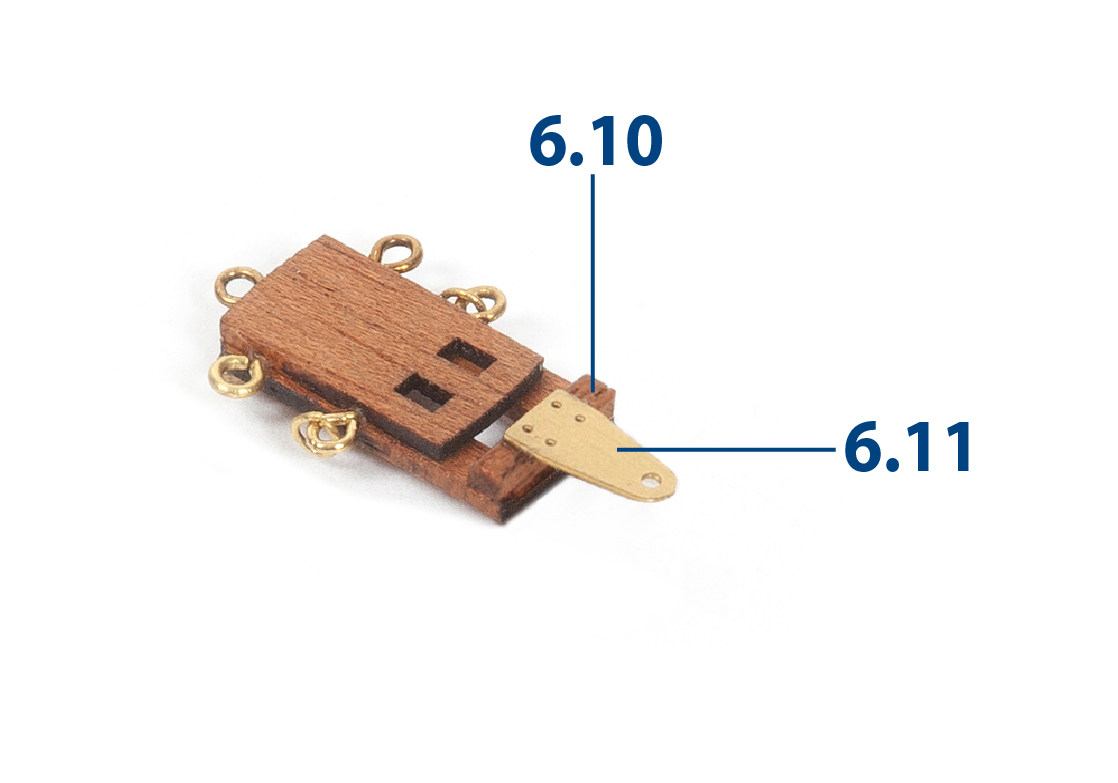
Cut parts 6.10 to length (2 x 2 x 10 mm mahogany, supplied in pack 5). Add parts 6.10 and 6.11 (supplied in pack 4).
Step 11
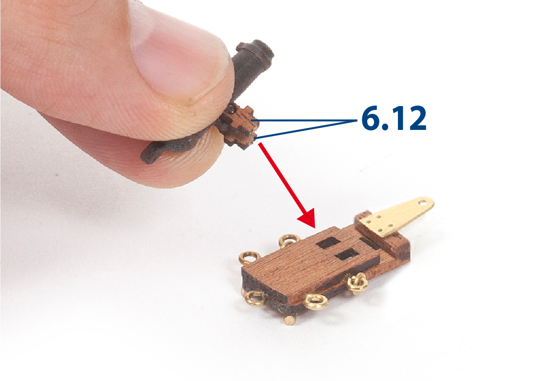
Fit parts 6.12 (supplied in pack 5) to a cannon barrel. Insert and glue the parts 6.12 into the carronade bases.
Step 12
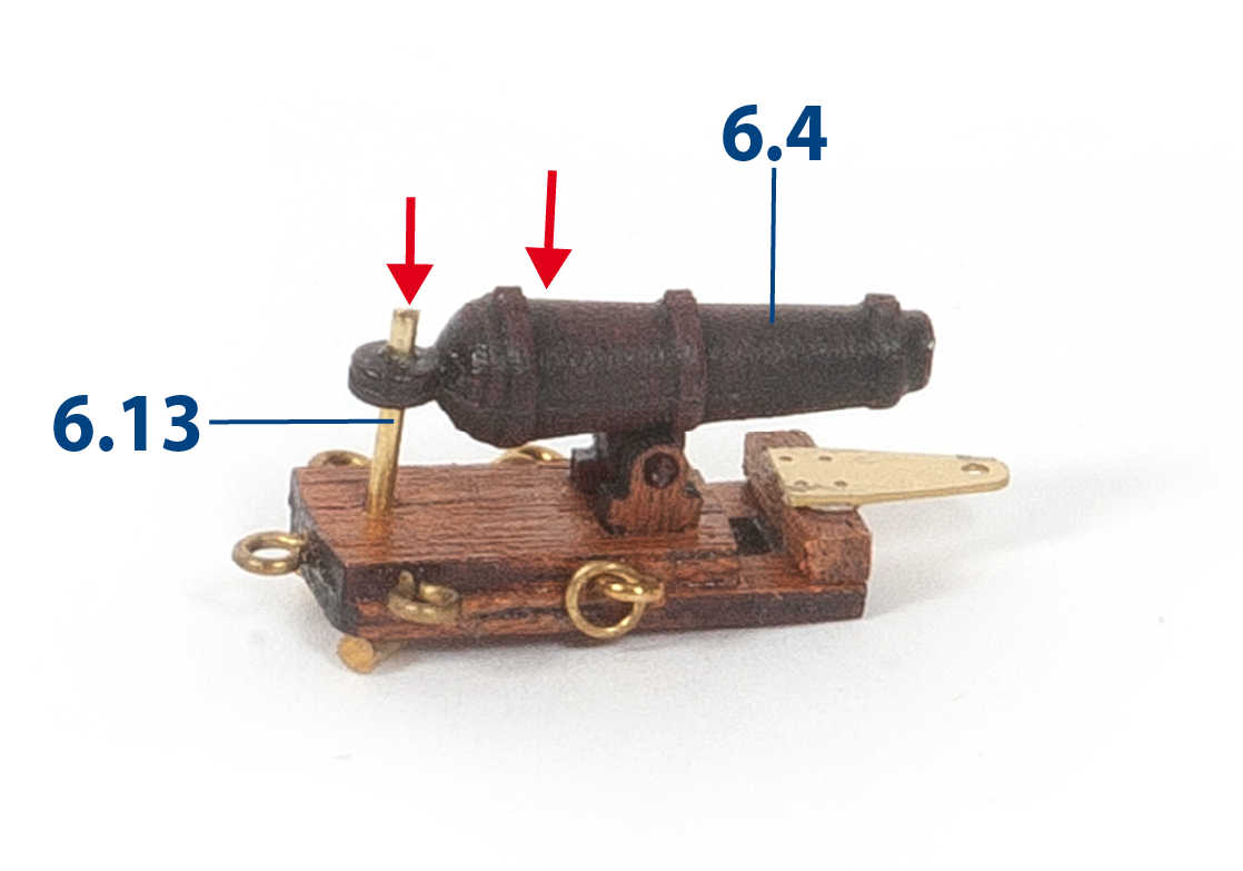
Make and glue the axles 6.13. In total you should be able to build 7 complete carronades.
Step 13
Bend the hinges 5.13 (supplied with pack 4) with a pair of pliers.
Step 14
Position and glue the two 6.6 canon barrels on the gun carriages. Add the parts 5.13.
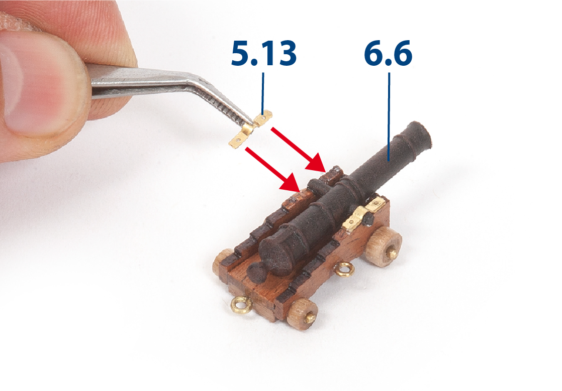
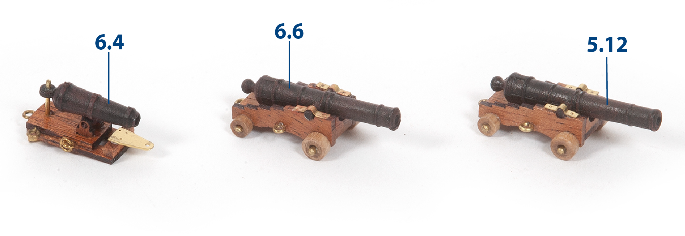
Step 15
The picture shows the appearance of the three types of armament carried on this ship:
6.4 = 32-pound carronades
6.6 = 18-pound bow chasers
5.12 = 24-pound cannons
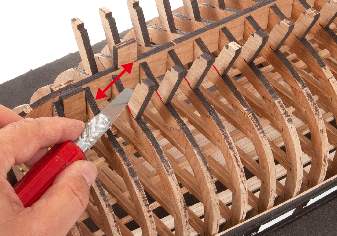
Step 1
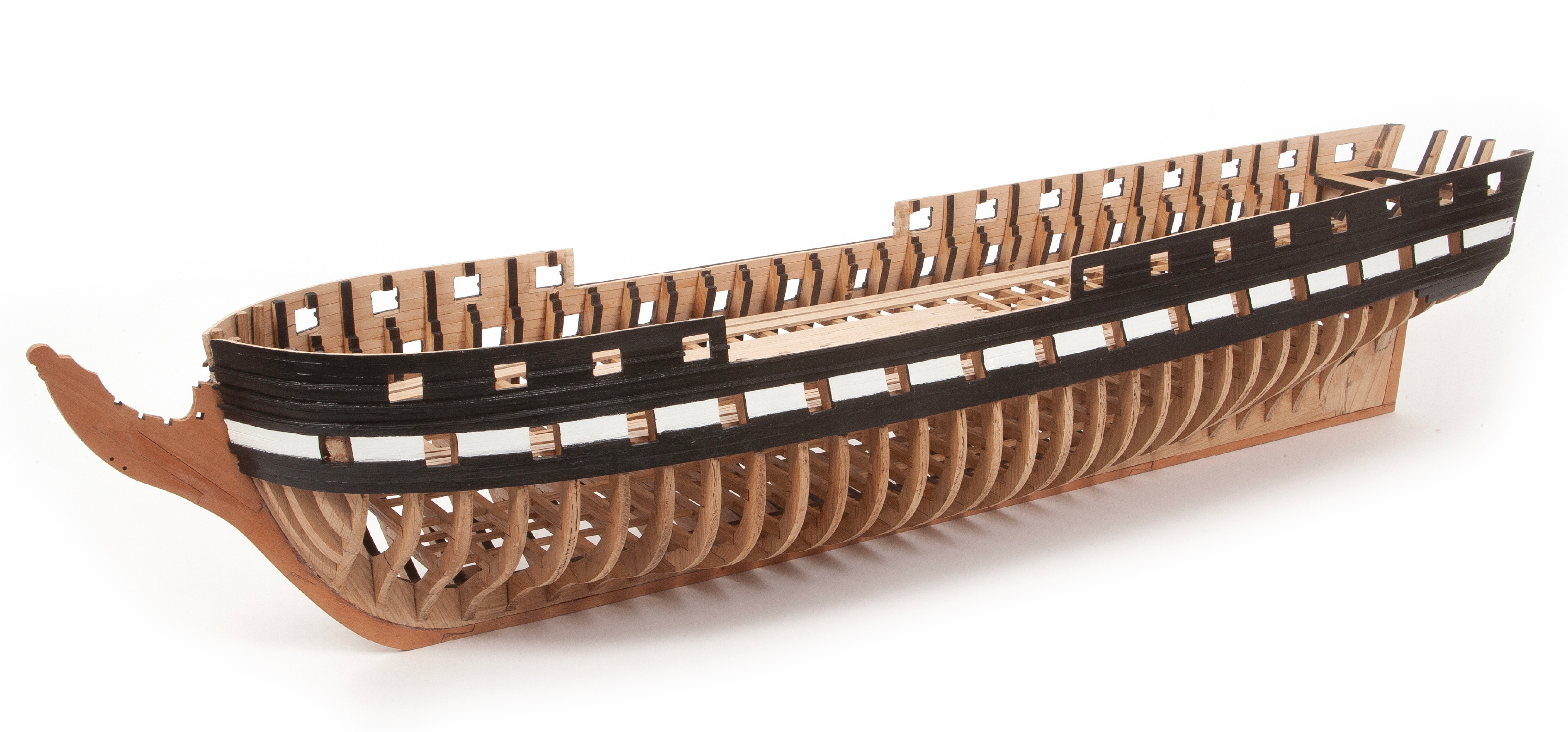
Separate the frame from the mounting base and place it with the legs facing upwards on foam or rags to protect it. Cut the legs off the frames.
Step 2
Also cut off the parts of the false keel that fitted into the mounting template.
Step 3
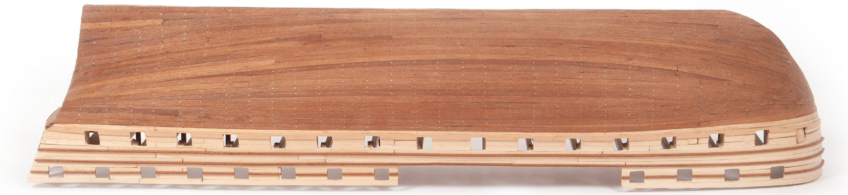
Now it is time to sand the lower part of the hull that will be visible without lining. Start sanding the areas where you cut the legs.
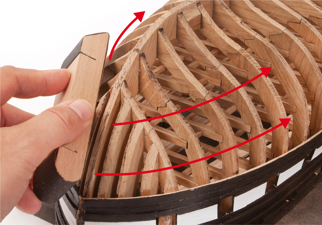
Step 4
It must be sanded smooth until there is no trace of the legs.
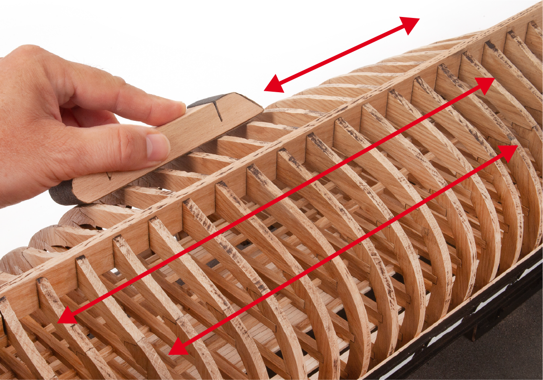
Step 5
Then sand the aft area to adjust the frames to the natural curvature of the hull.
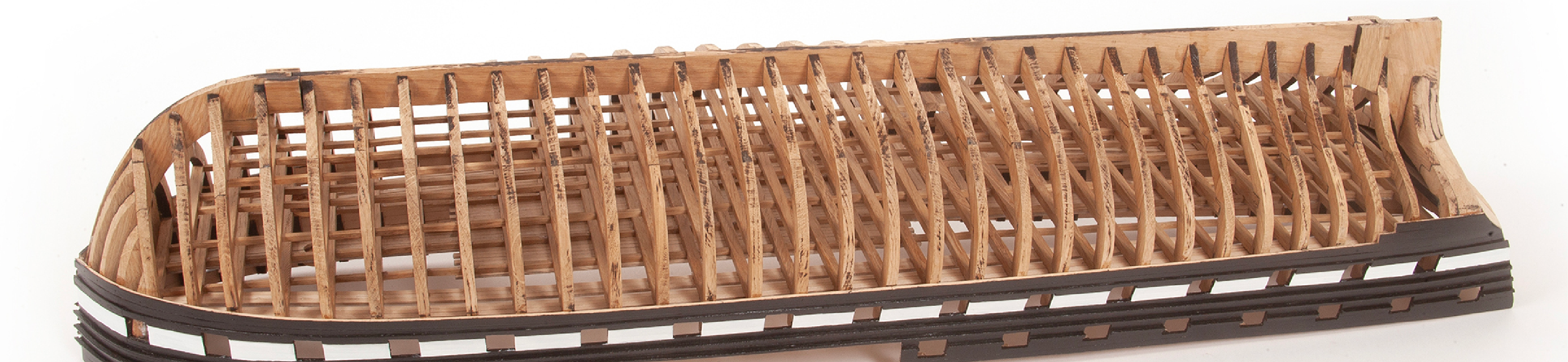
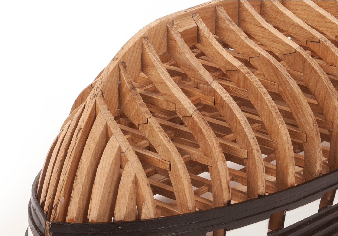
Step 6
The bow area should look more or less as shown in the picture. If you want to plank the lower part of the hull, now is the time to do it before adding more parts to your model.
If you do not want to plank the lower part of the hull, continue to Stage 29.
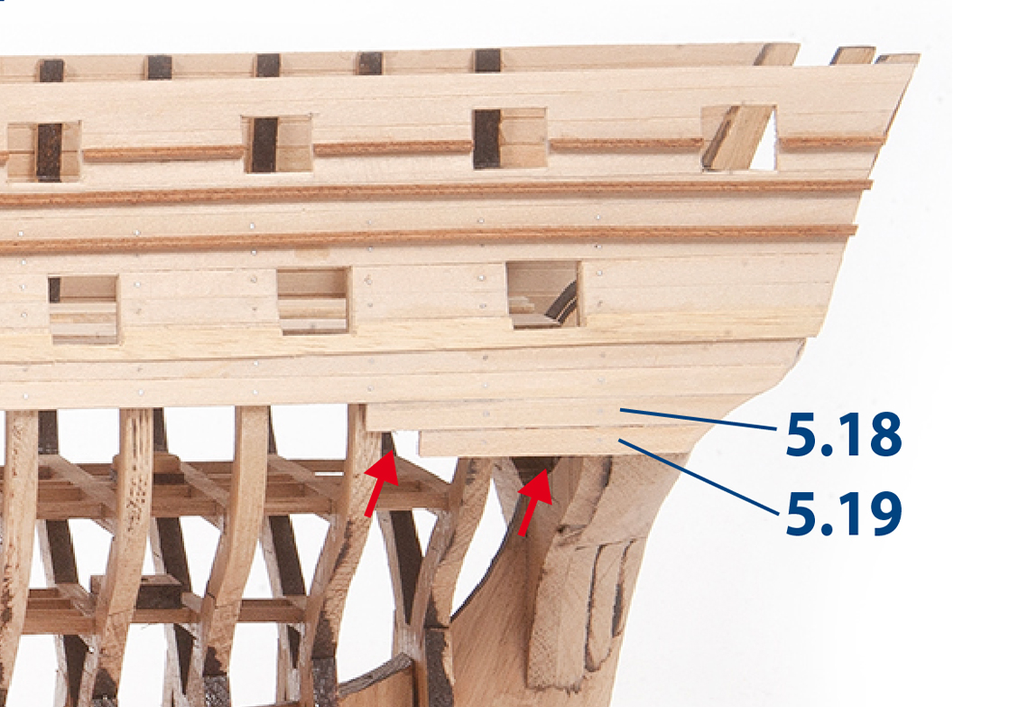
Step 7
Planking the hull
Before proceeding with the following steps, please check that parts 5.18 and 5.19 (image a) have not been fitted, and remove them if necessary.
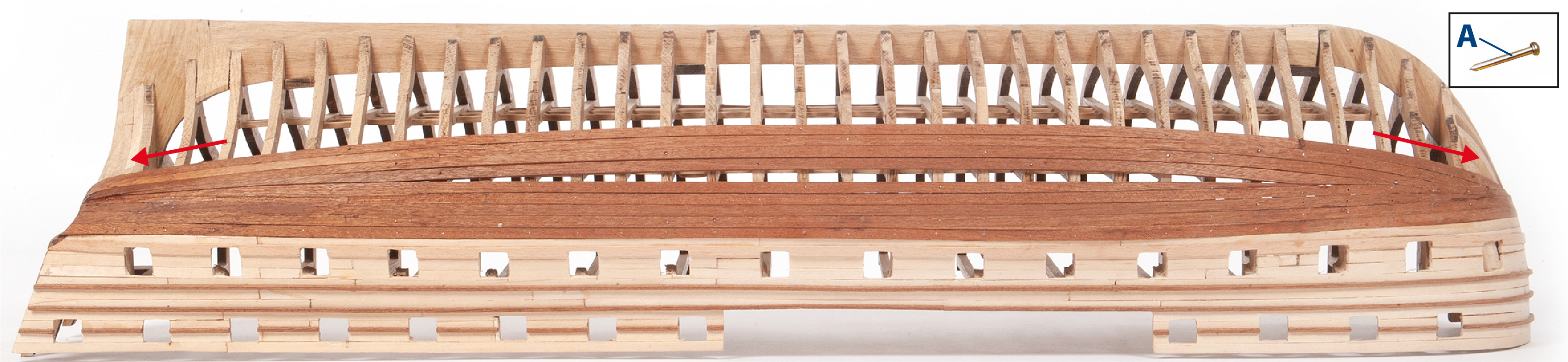
Cut to size and plank the rear part of the hull with mahogany strips.
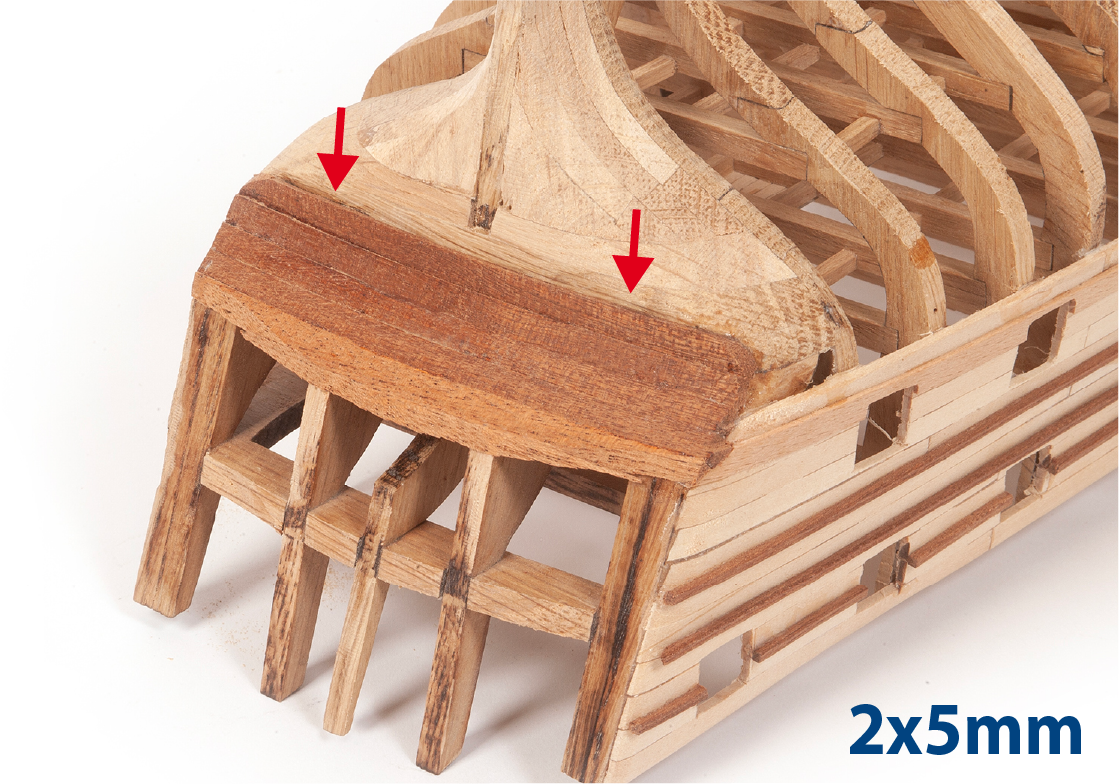
Step 8
Moisten and bend the mahogany strips to adapt them to the curvature of the hull.
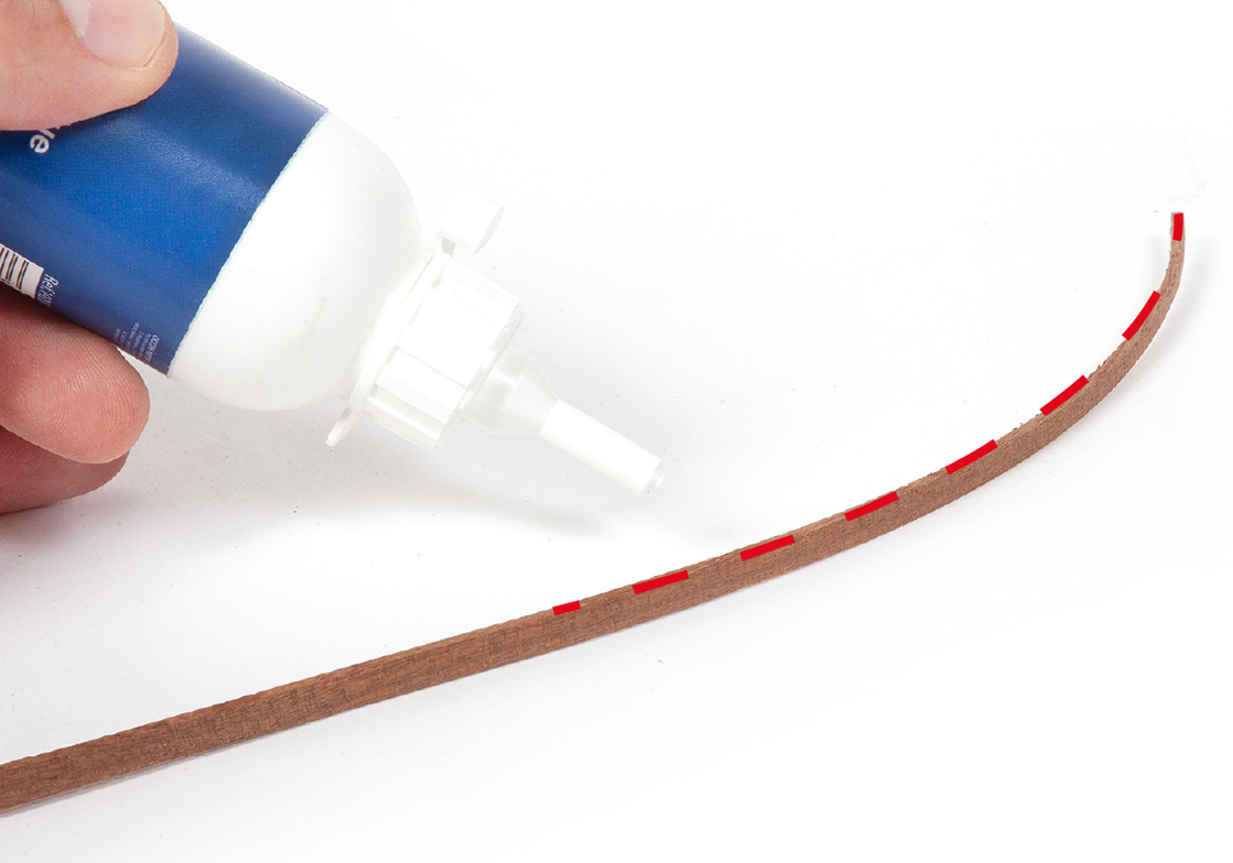
Step 9
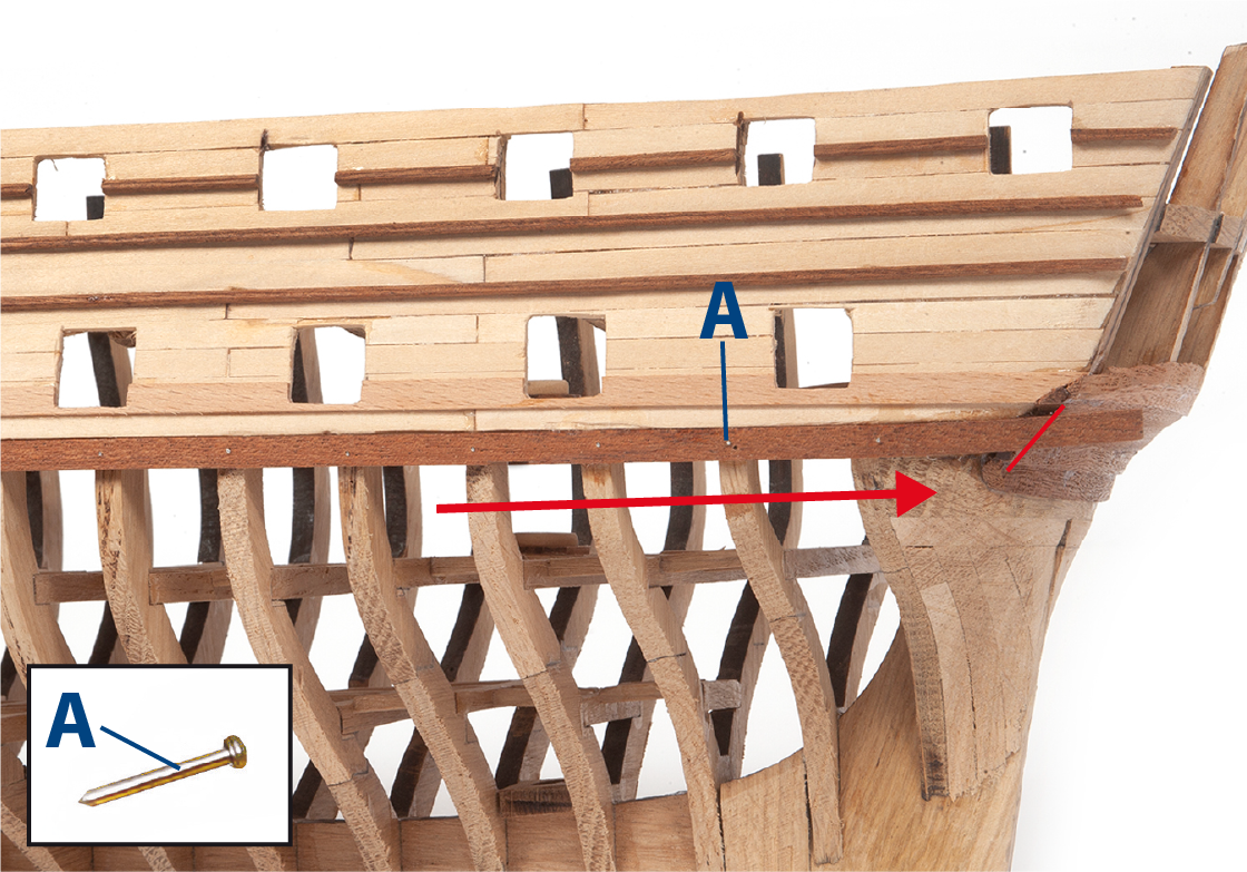
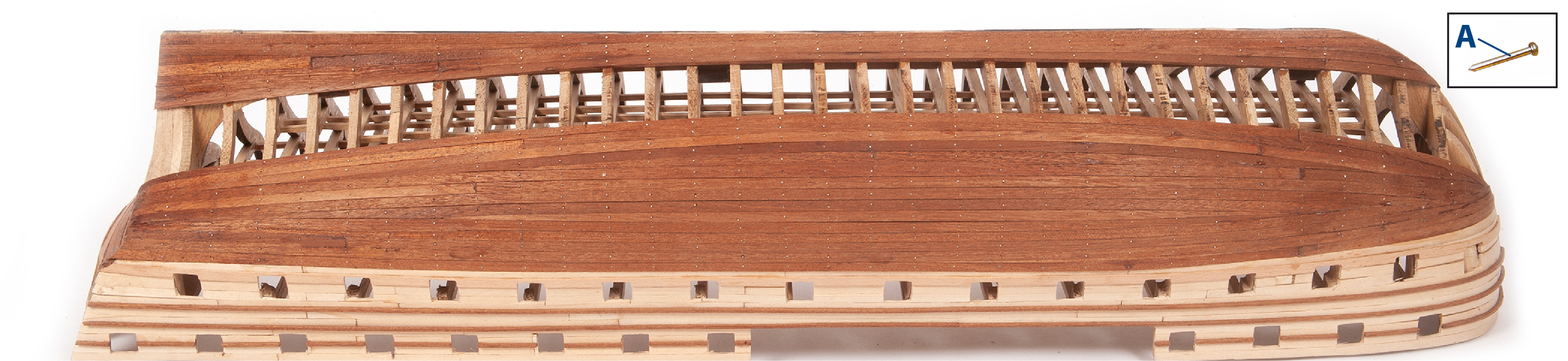
Then, fix the strips in place using wood glue or fast-drying adhesive and small nails (A).
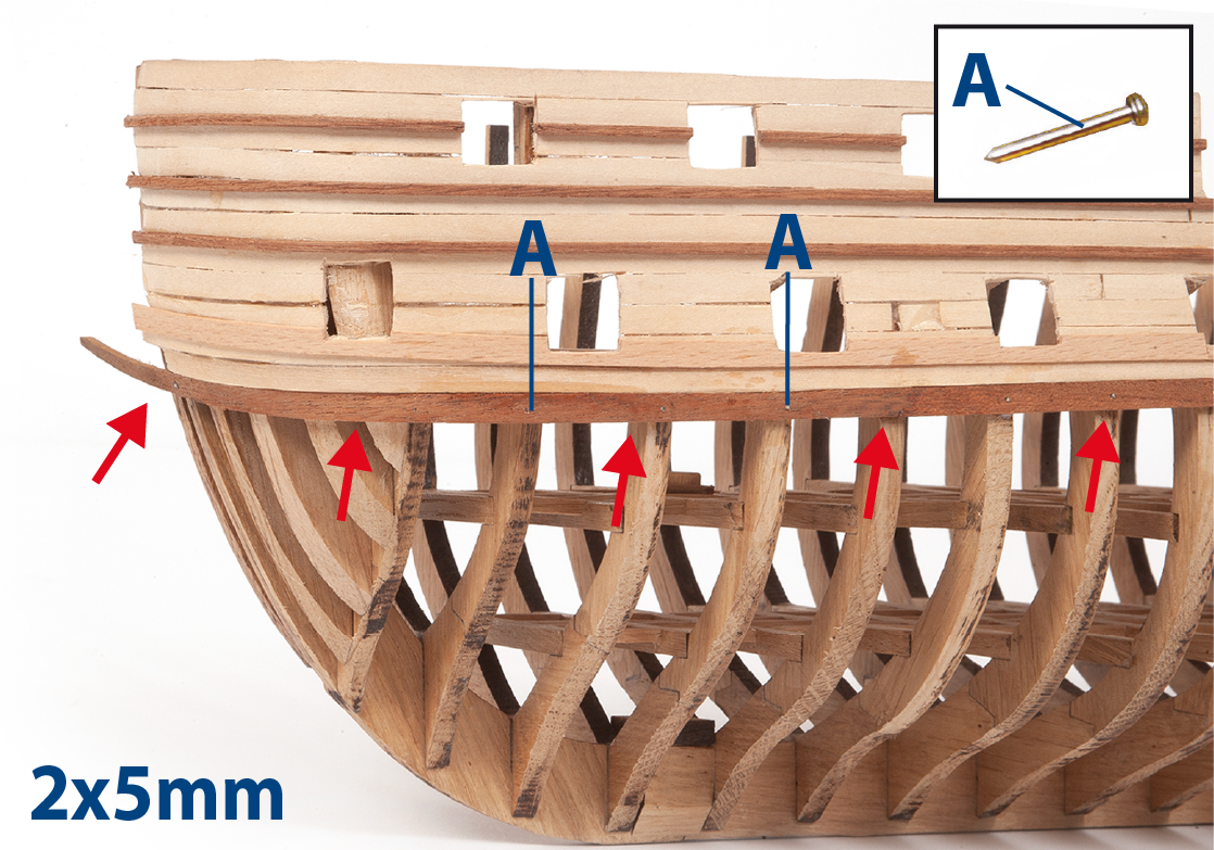
Step 10
Continue along the entire length of the hull, adjusting the strips at the stern.
Step 11
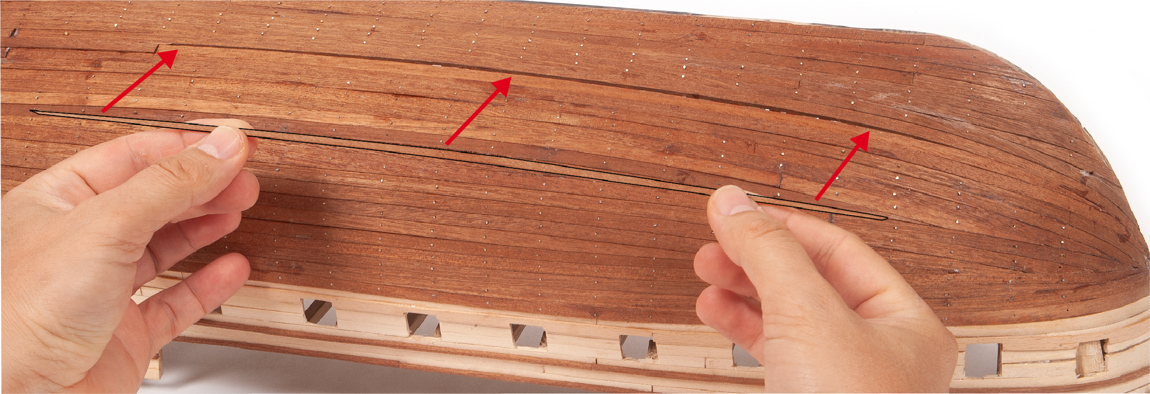
Refer to the image to see how the first strip should be positioned. Cut off the nail heads once the strips are securely fixed.
Step 12
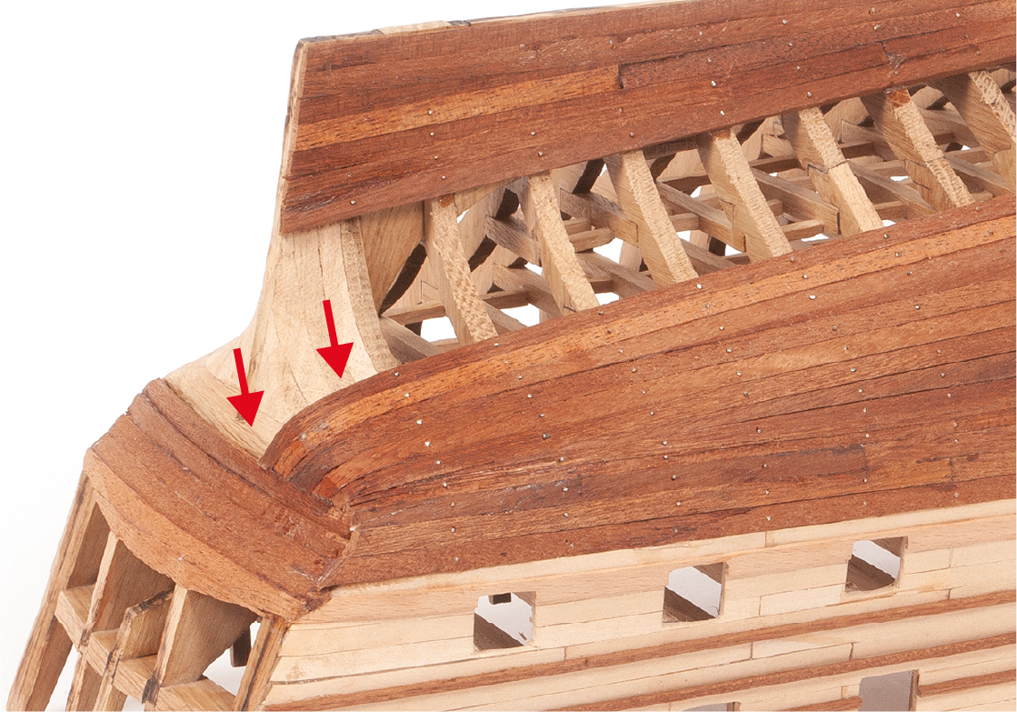
As you add more strips, you will need to adjust them at the bow as shown in the image.
Step 13
Observe the progress of the planking already placed. Each strip must be adjusted properly.
Step 14
See how the strips should be adjusted around the stern area of the hull.
Step 15
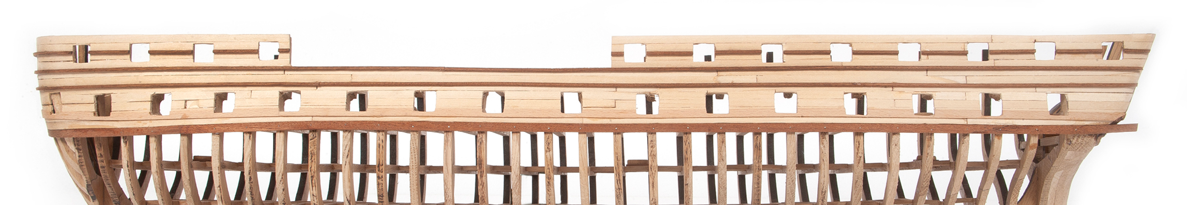
The image shows how the hull planking will look as it is gradually closed.
Step 16
Adjust the pieces to close any small gaps that may have remained in the hull.
Step 17
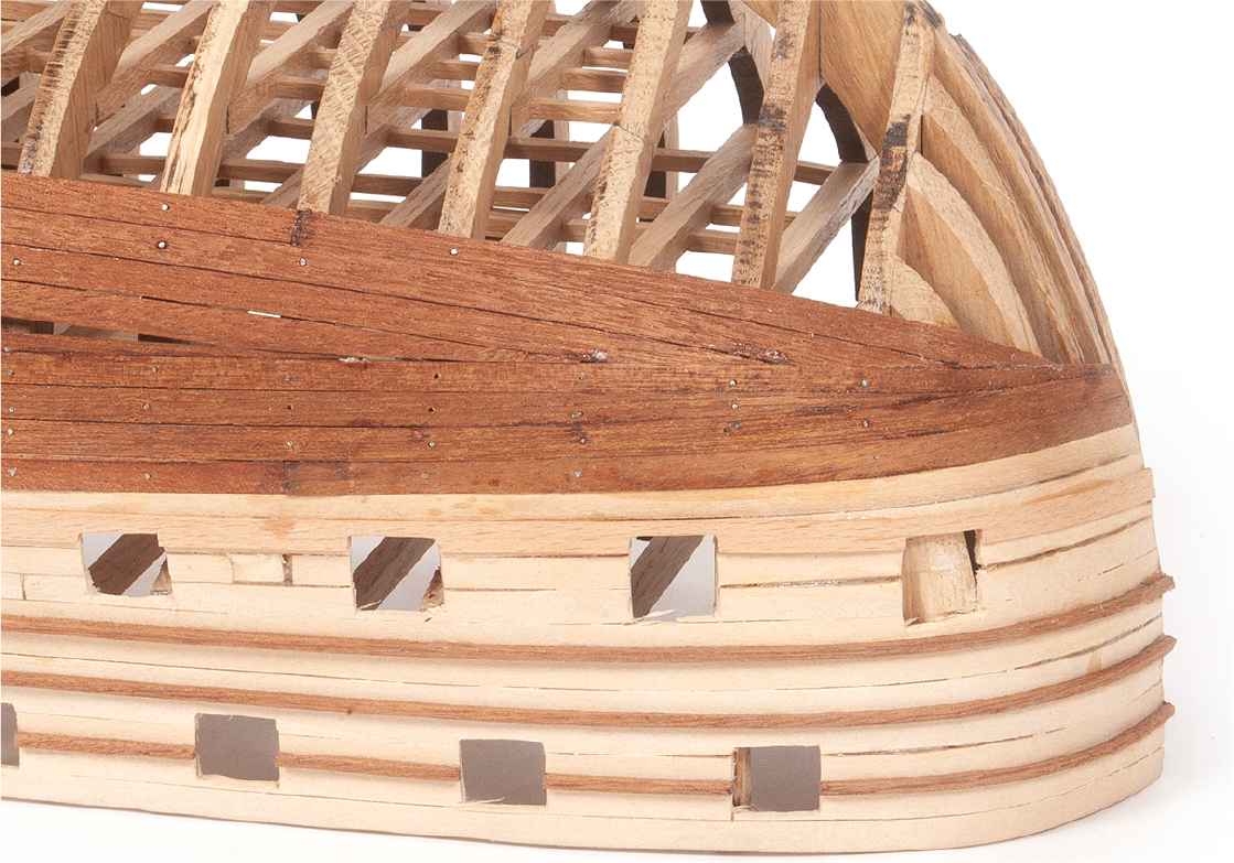
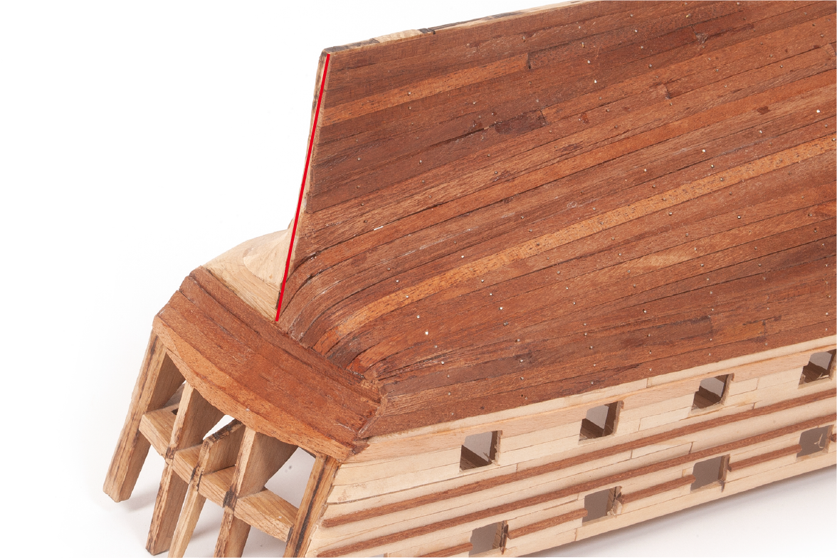
Refer to the image to see the appearance of the rear of the hull.
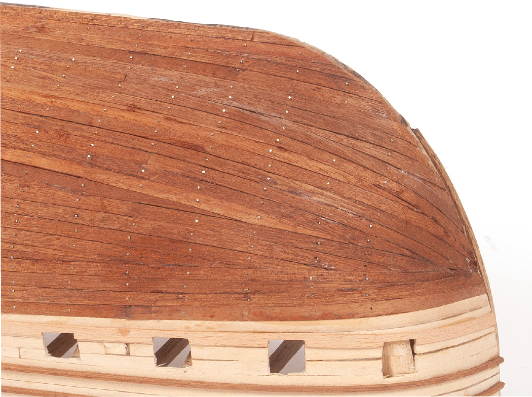
Step 18
Refer to the image to see the appearance of the front of the hull.
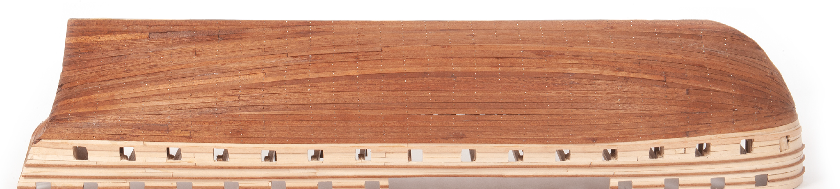
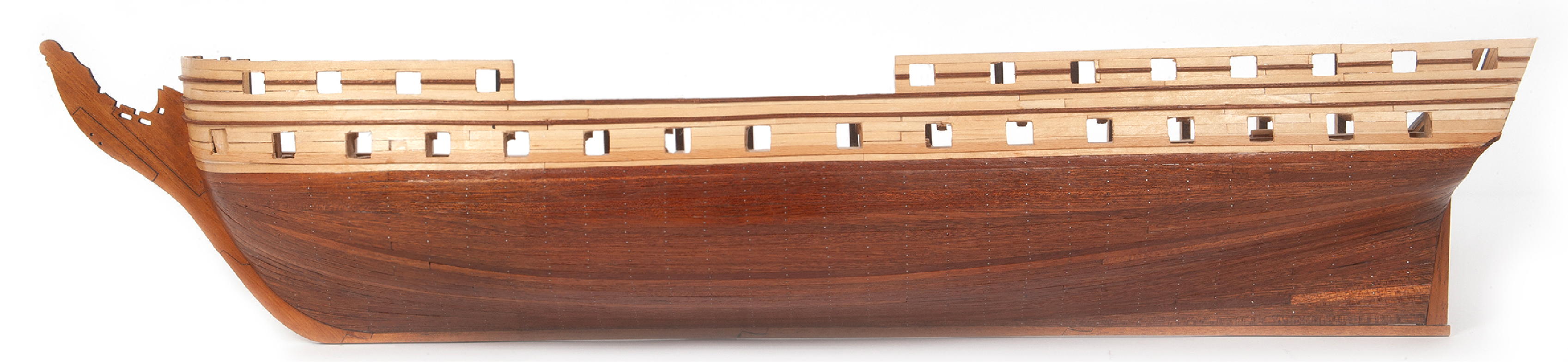
Step 19
The image shows how the fully planked hull should look.
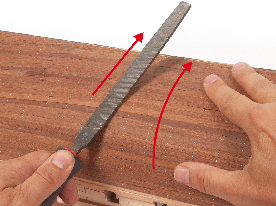
Step 20
Use a flat file to file down the nail heads until they are flush with the planking.
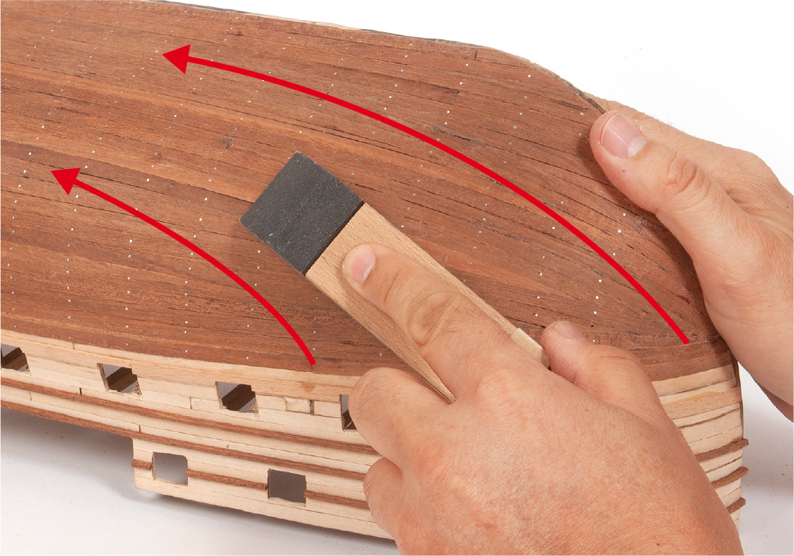
Step 21
Sand the entire hull planking to make it smooth and even.
Step 22
Refer to the image to see the finished and sanded hull planking.
Step 23
Apply clear varnish over the entire hull planking if you wish to preserve the natural color of the wood. If you intend to paint the upper part, varnish only the mahogany planking.
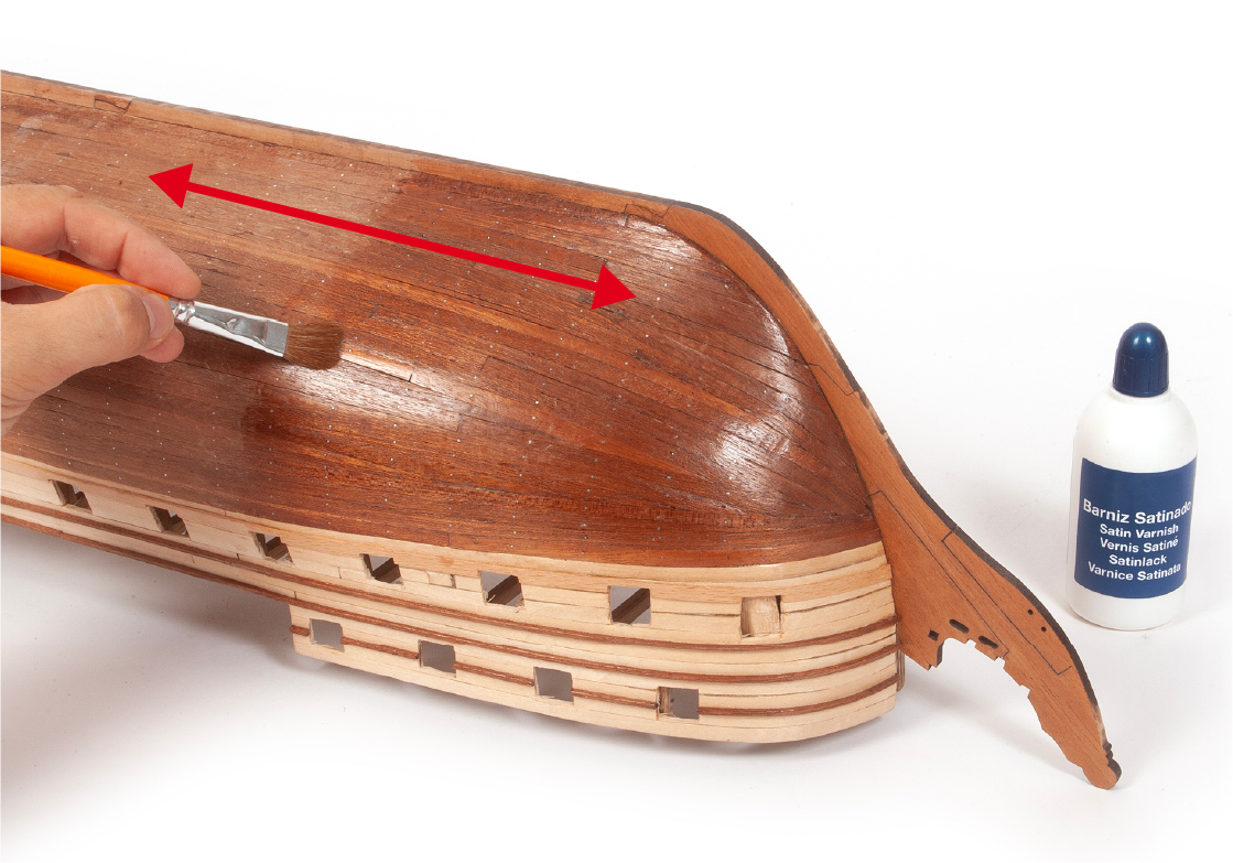
Step 24
This will be the appearance of the finished hull planking.
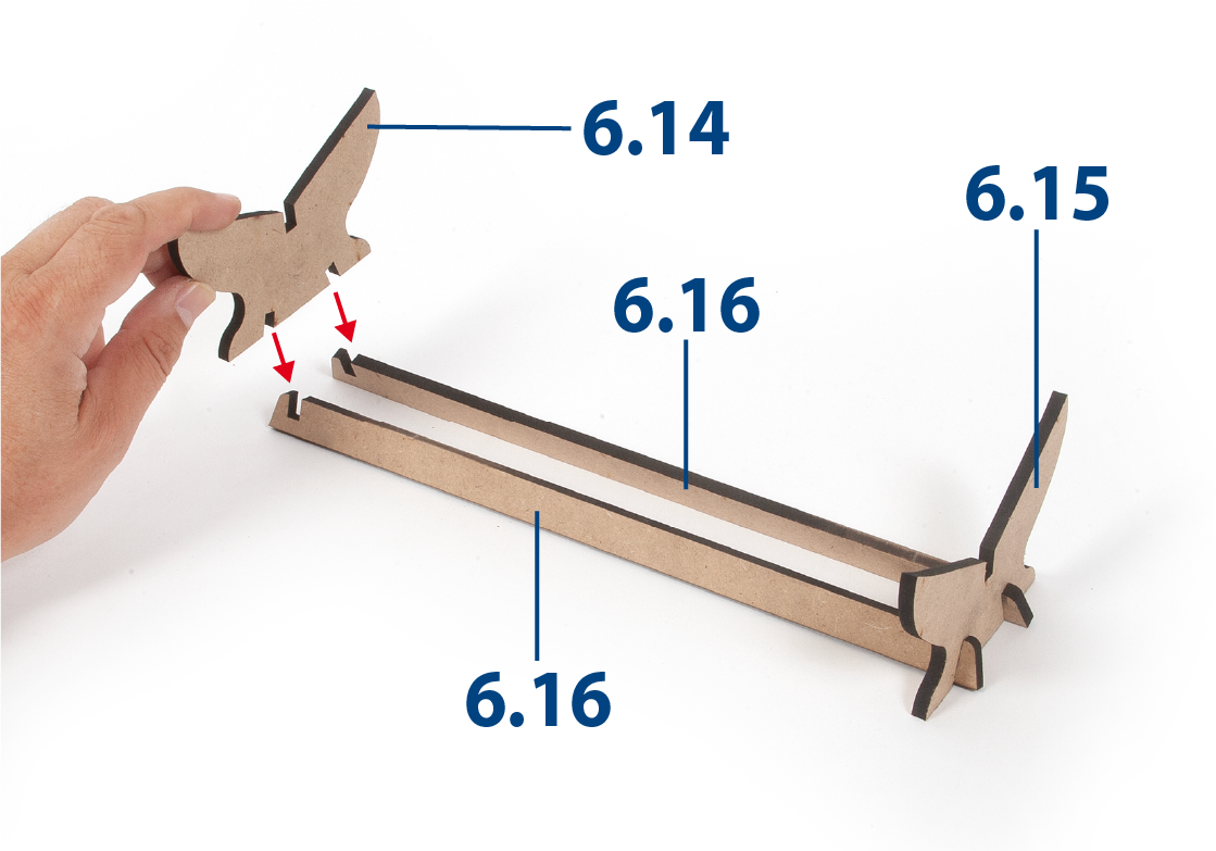
Step 1
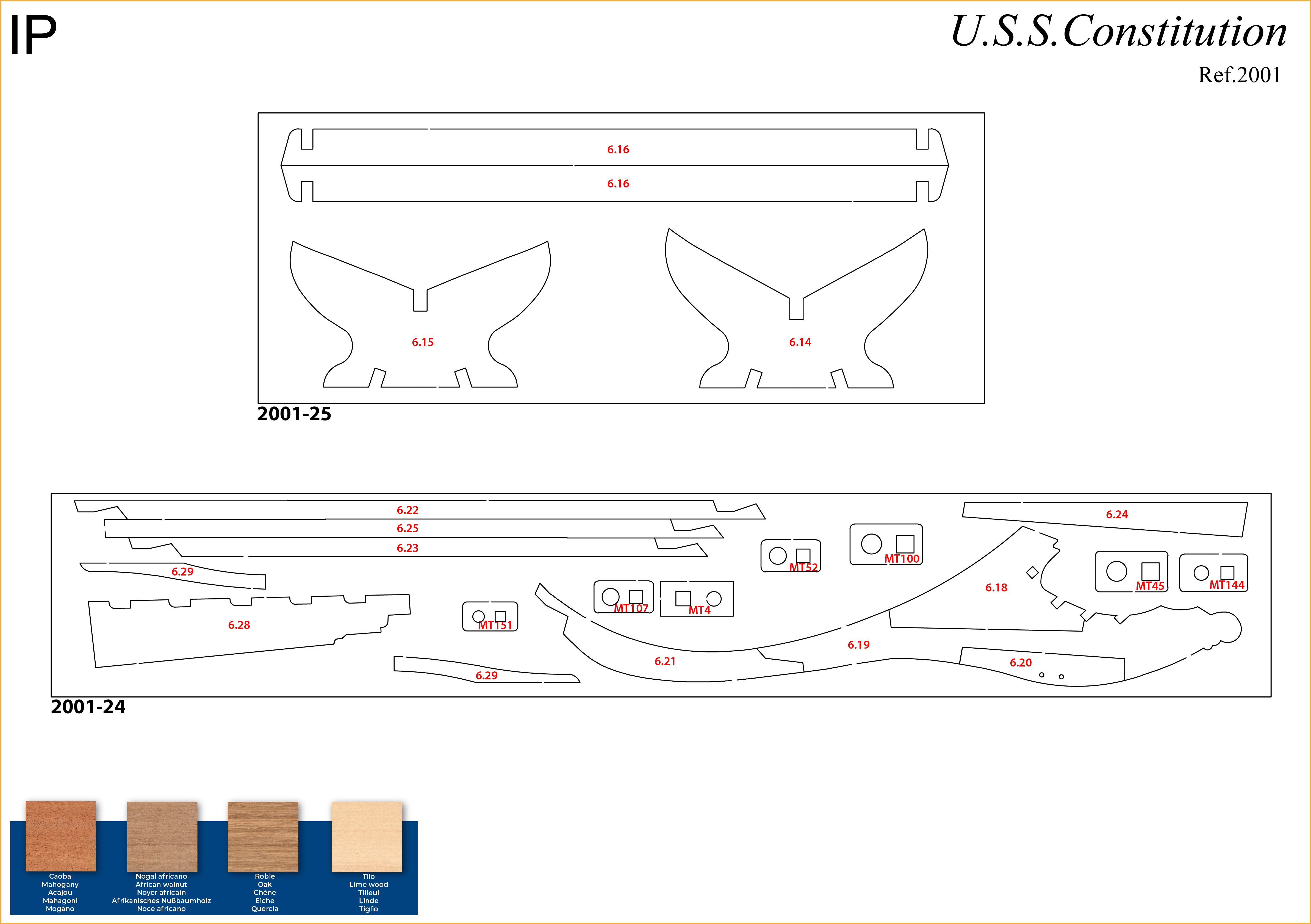
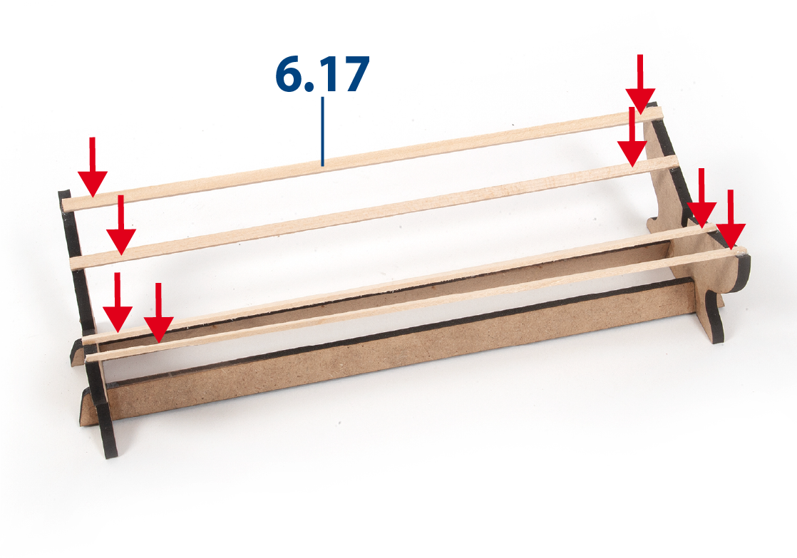
Construct the hull support from parts 6.14 to 6.16 (board 2001-25).
Step 2
Glue some battens 6.17 (2 x 5 x 259 mm, supplied in pack 3) evenly spaced.
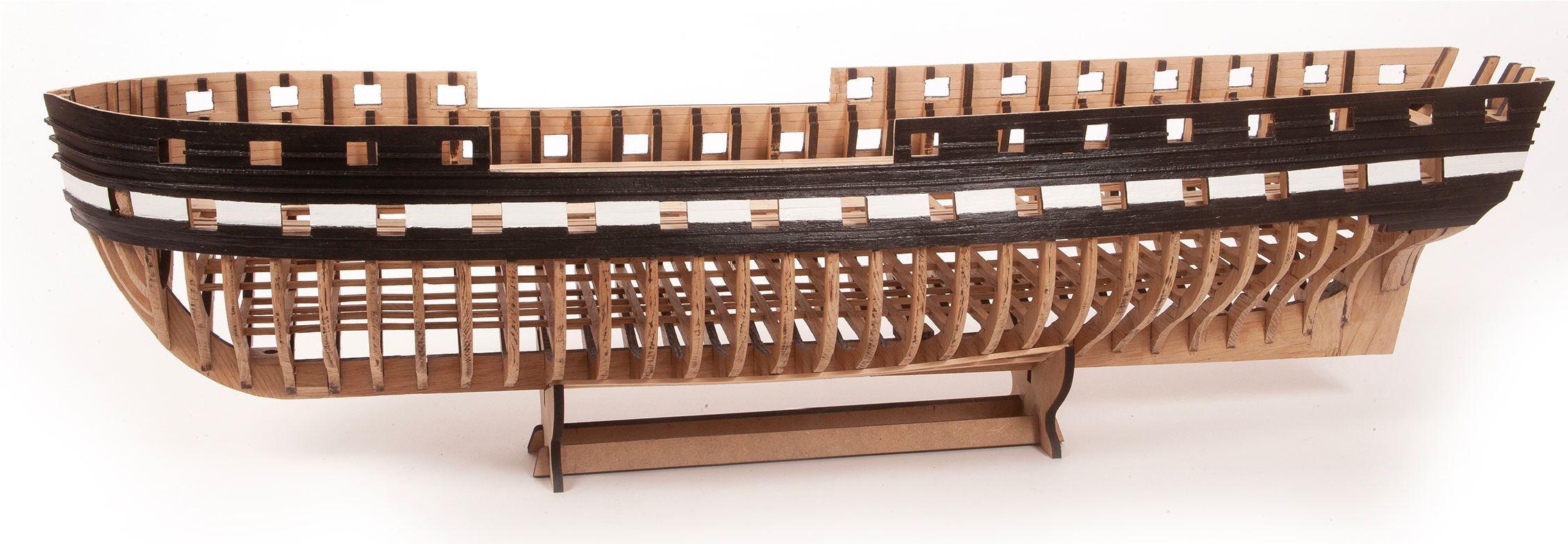
Step 3
Check how the hull support keeps the hull stable.
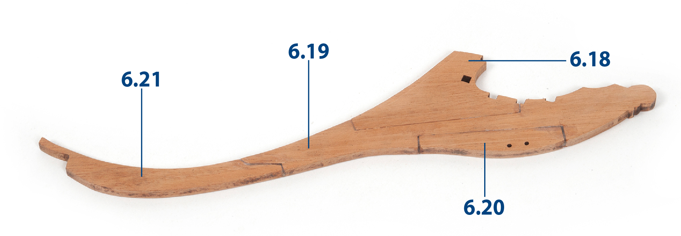
Step 4
Parts 6.18 to 6.21 form the stem of the ship.
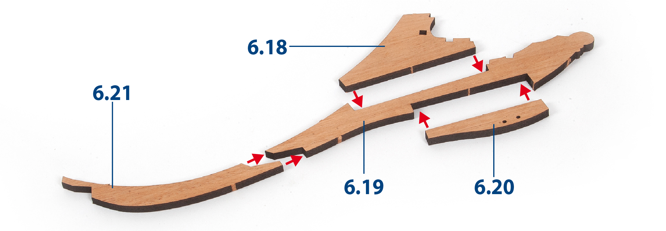
Step 5
Glue the parts together as shown in the picture.
Step 6
File the planks in the bow area to allow the stem to be inserted.
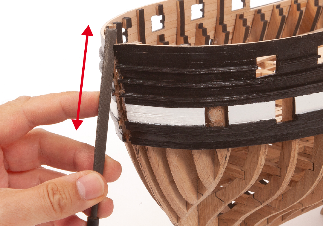
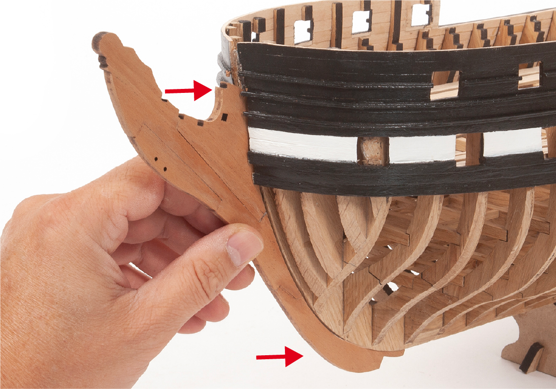
Step 7
Insert and glue the stem into the bow of the hull.
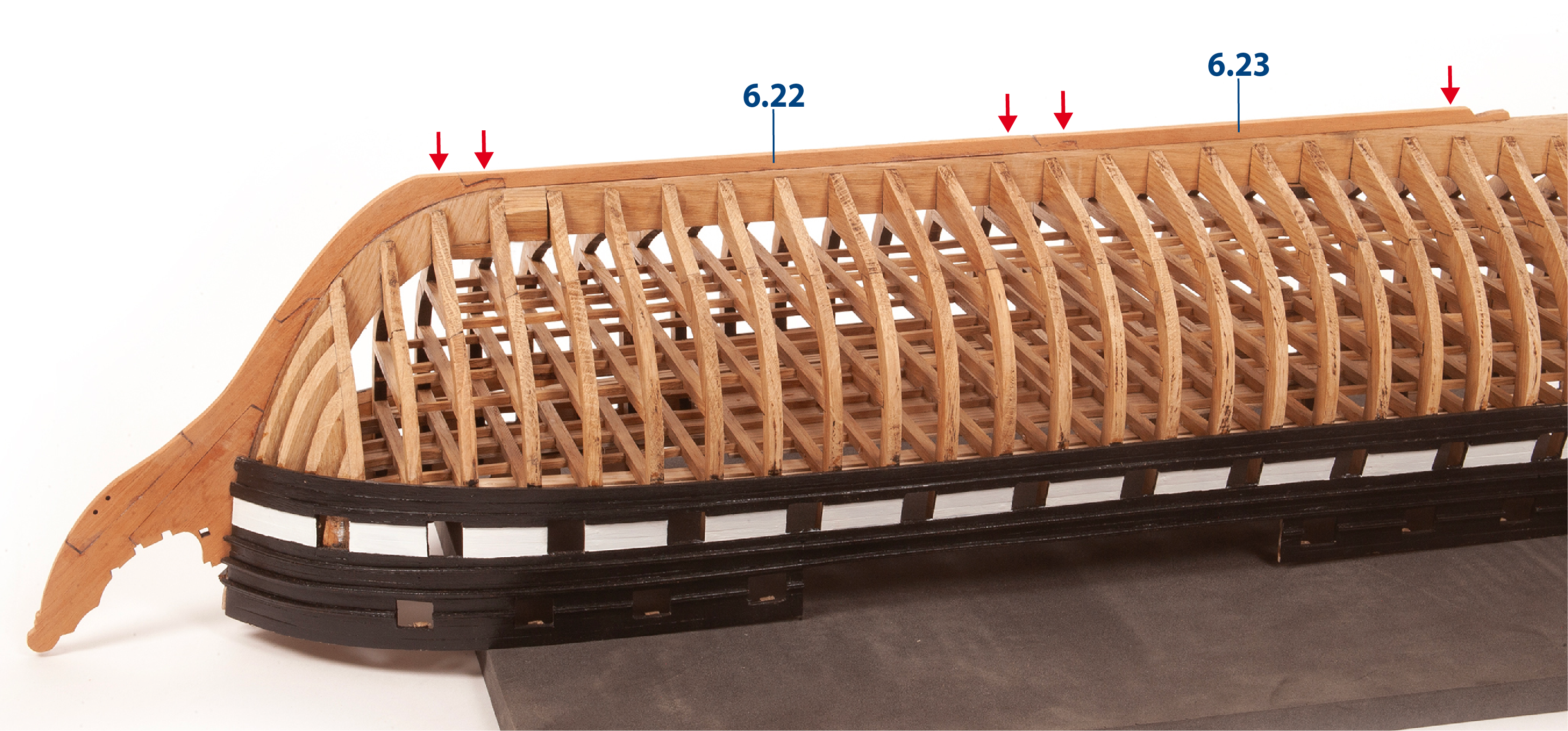
Step 8
Fit and glue parts 6.22 and 6.23 which will continue the stem.
Step 9
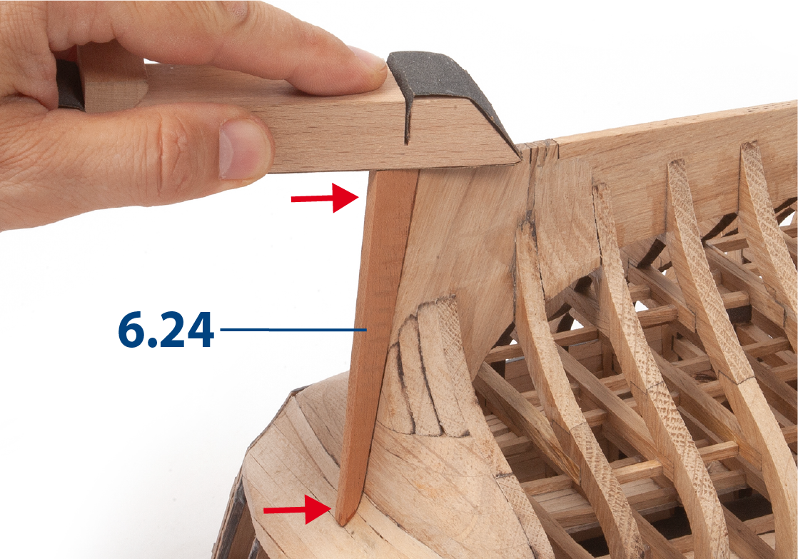
Adjust the sternpost, part 6.24, to fit the stern.
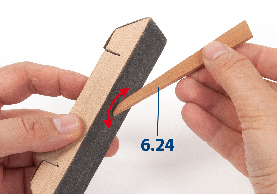
Step 10
Glue the part 6.24 and use a sander to even it out with the false keel.
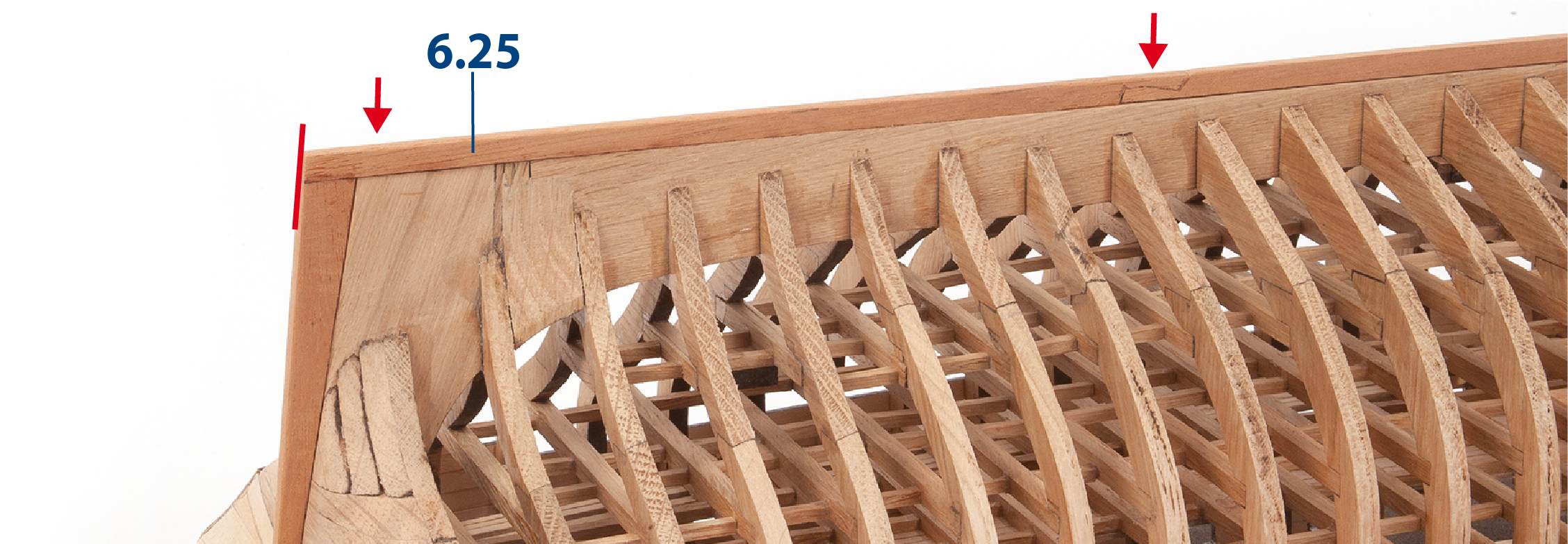
Step 11
Glue piece 6.25 to extend the keel. Then align it with the sternpost.
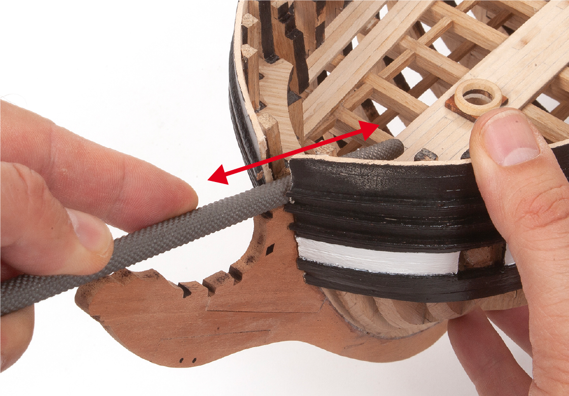
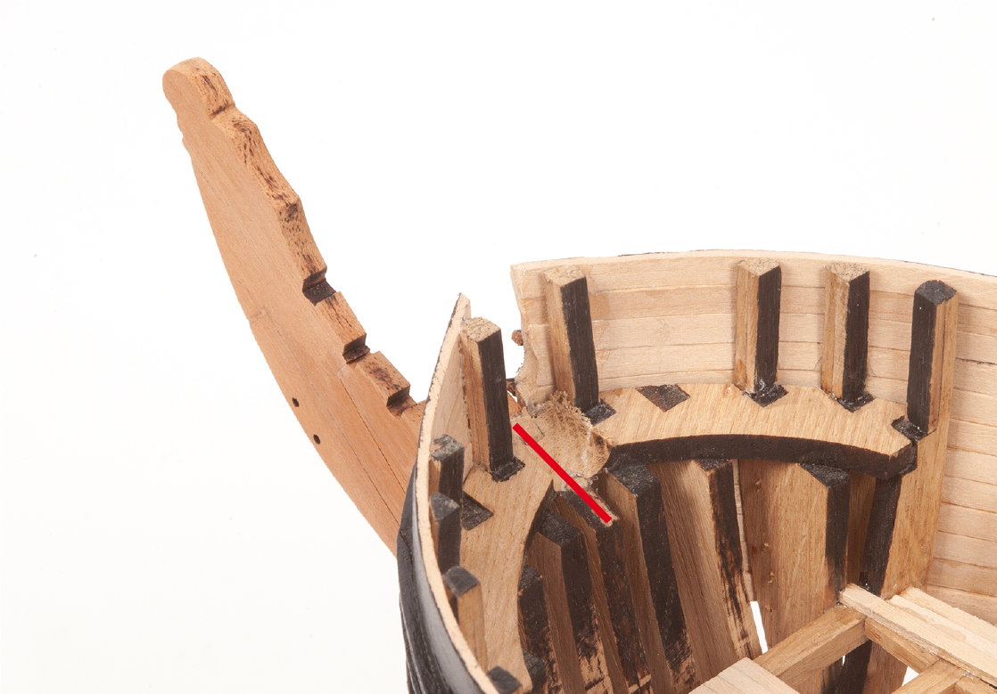
Step 12
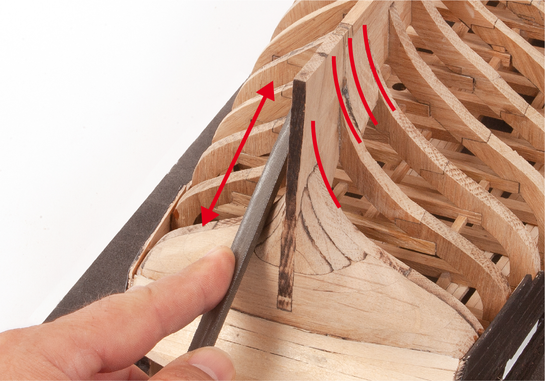
Using a round file, create a groove at the front of the hull.
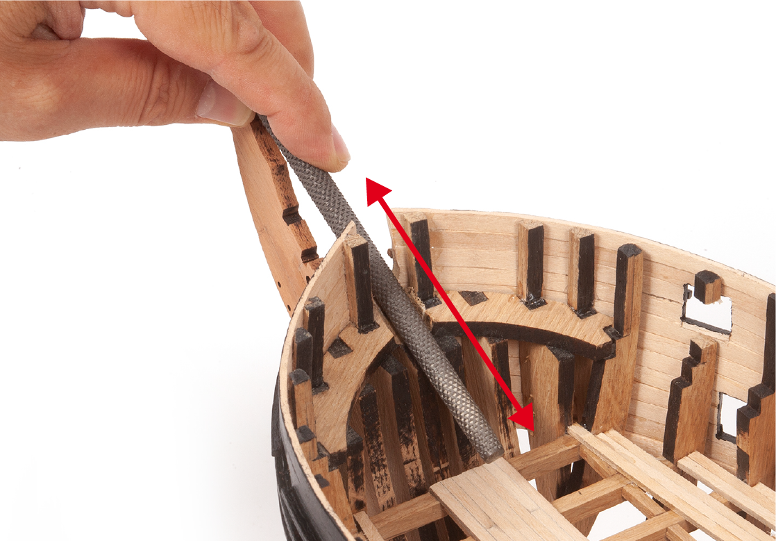
Step 13
File to achieve the correct angle between the groove and the stem.
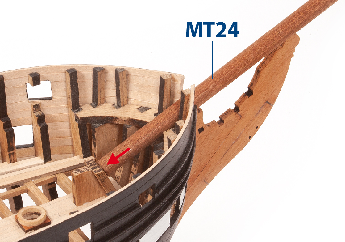
Step 14
Use part MT24 to carry out checks and adjustments.
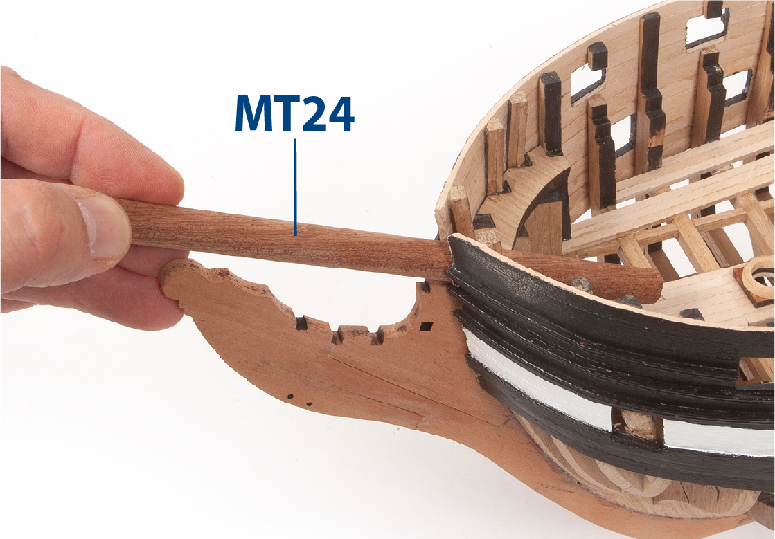
Step 15
The MT24 piece will rest on the top of the stem and in the groove.
Step 1
Glue part 6.26 properly adjusted and centred on part 6.27 as shown (supplied with pack 2).
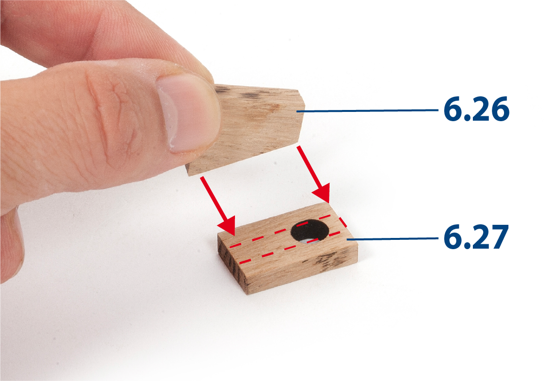
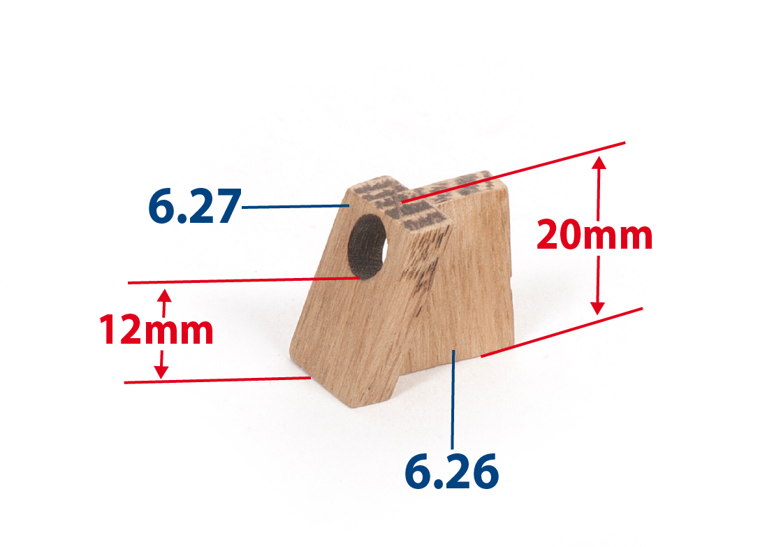
Step 2
Match part 6.27 with part 6.26. Then sand the top of both pieces to a height of 20 mm.
Step 3
Position the assembly as shown in the picture.
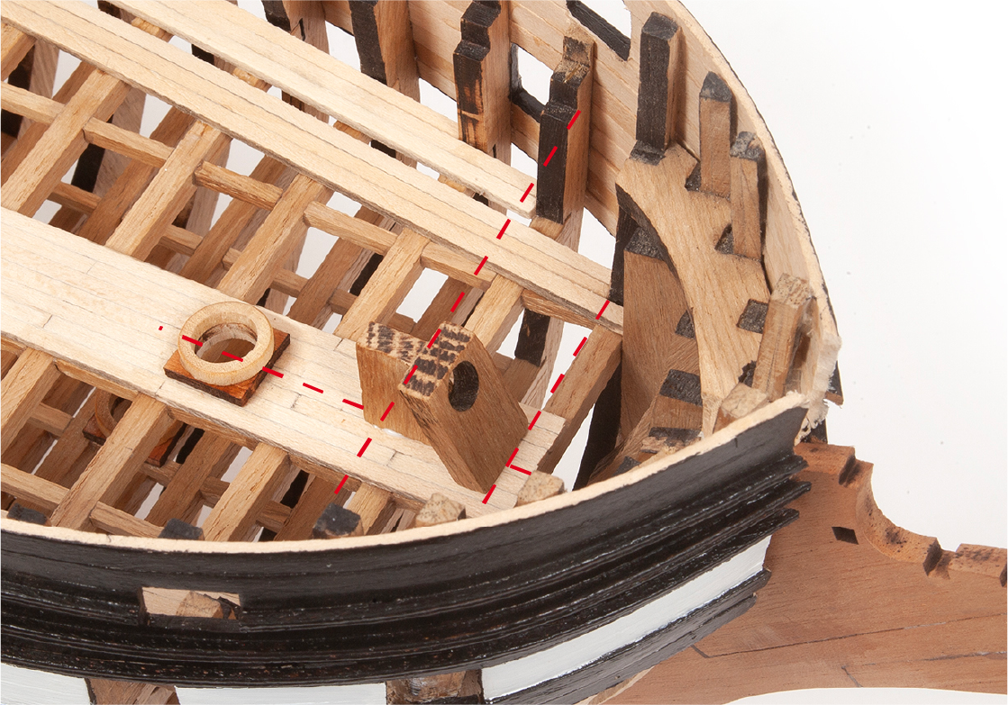
Step 4
Check that part MT24 fits into the hole in part 6.27, and that it rests on the flats of the stem and false keel. When this is done, glue parts 6.26 and 6.27 centred on the deck. Reserve part MT24 for later use.
Step 5
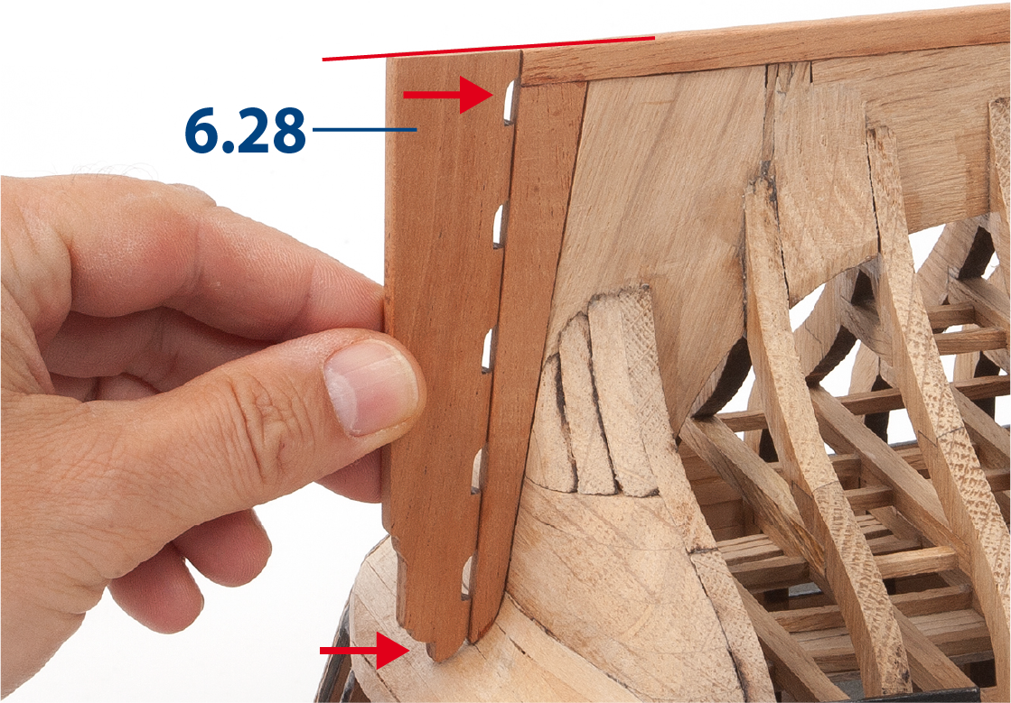
Use a sanding block to round off the end of part 6.28 and fit it to the stern of the boat as shown in step 7.
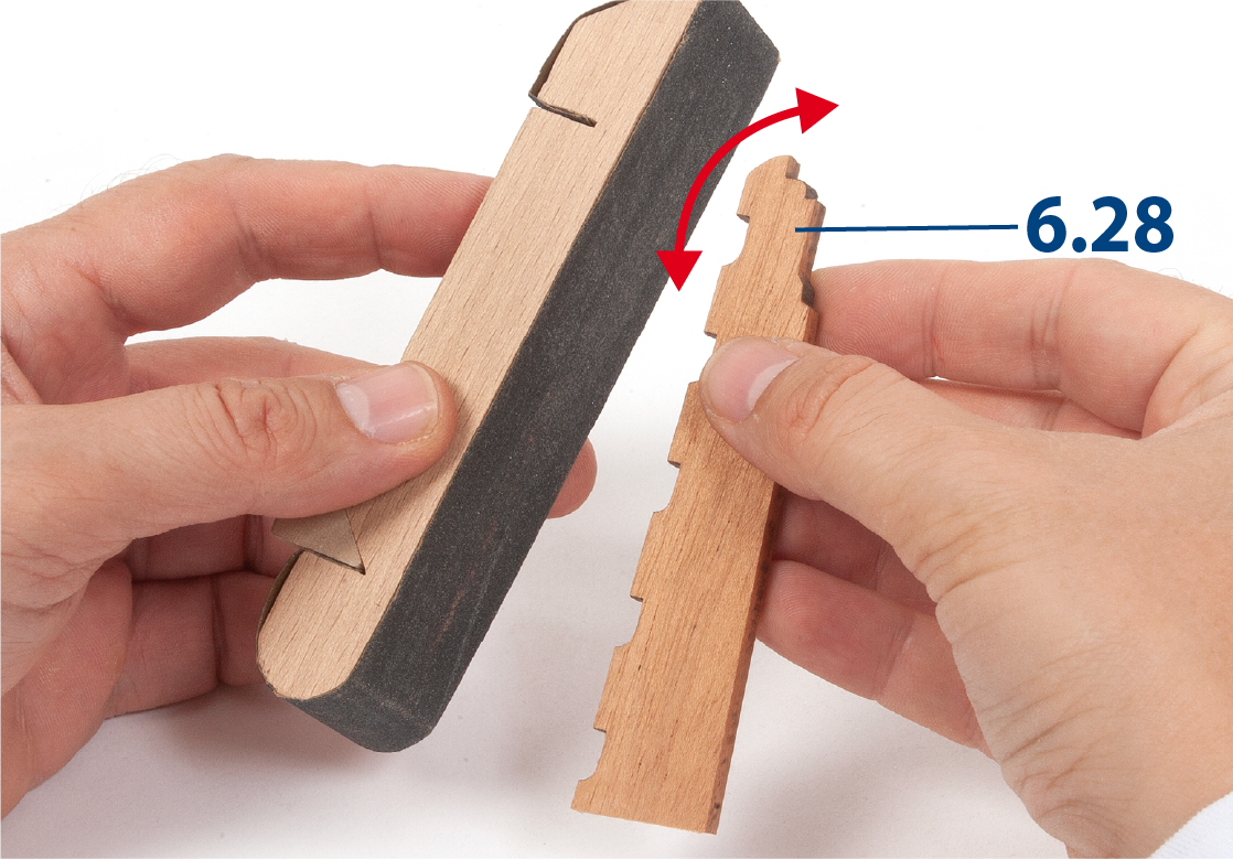
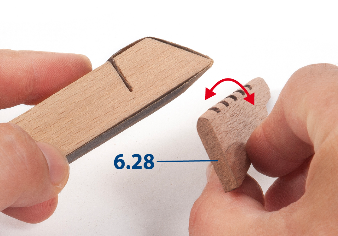
Step 6
Round off the edge with the recesses on part 6.28.
Step 7
Present the rudder blade at the stern of the boat and adjust the rudder height.
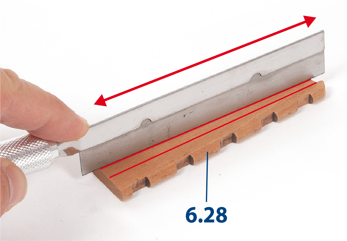
Step 8
Use a saw or similar to mark the grooves that simulate the rudder blade planking.
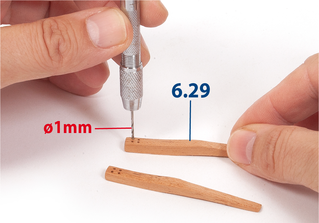
Step 9
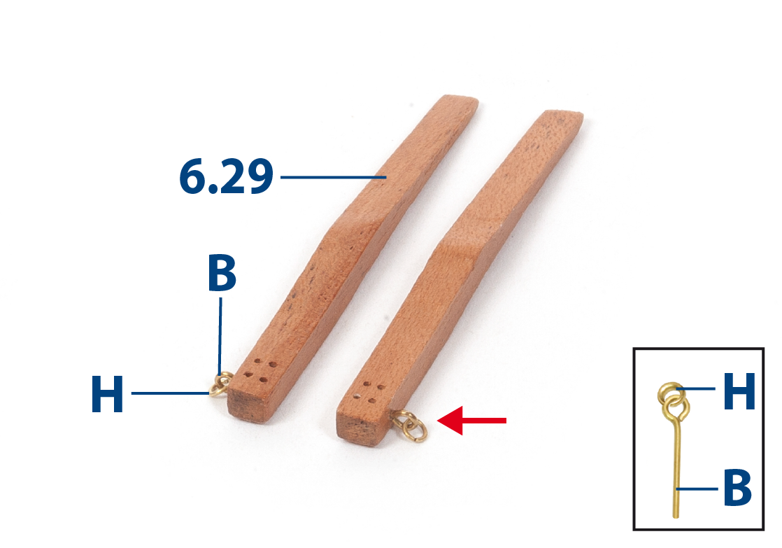
Use a drill to drill four holes in each part 6.29 (see image in step 11).
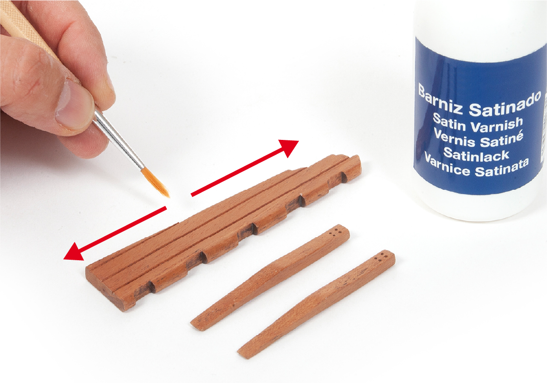
Step 10
Sand and varnish the parts with varnish.
Step 11
Drill holes for the insertion of eyebolts B and H-rings in parts 6.29 as shown in the picture.
Step 12
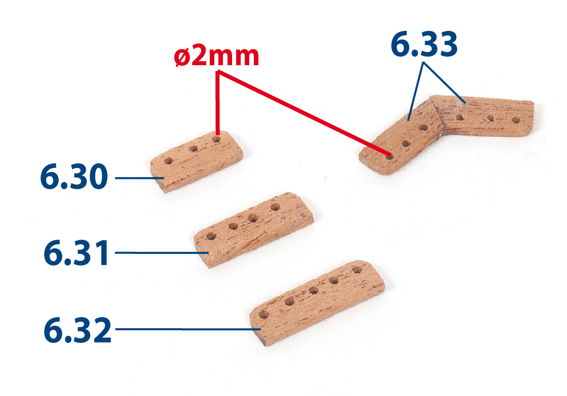
Make the parts indicated in the picture using the deck plan as a guide. Use 2 x 6 mm mahogany strips (supplied in pack 5).
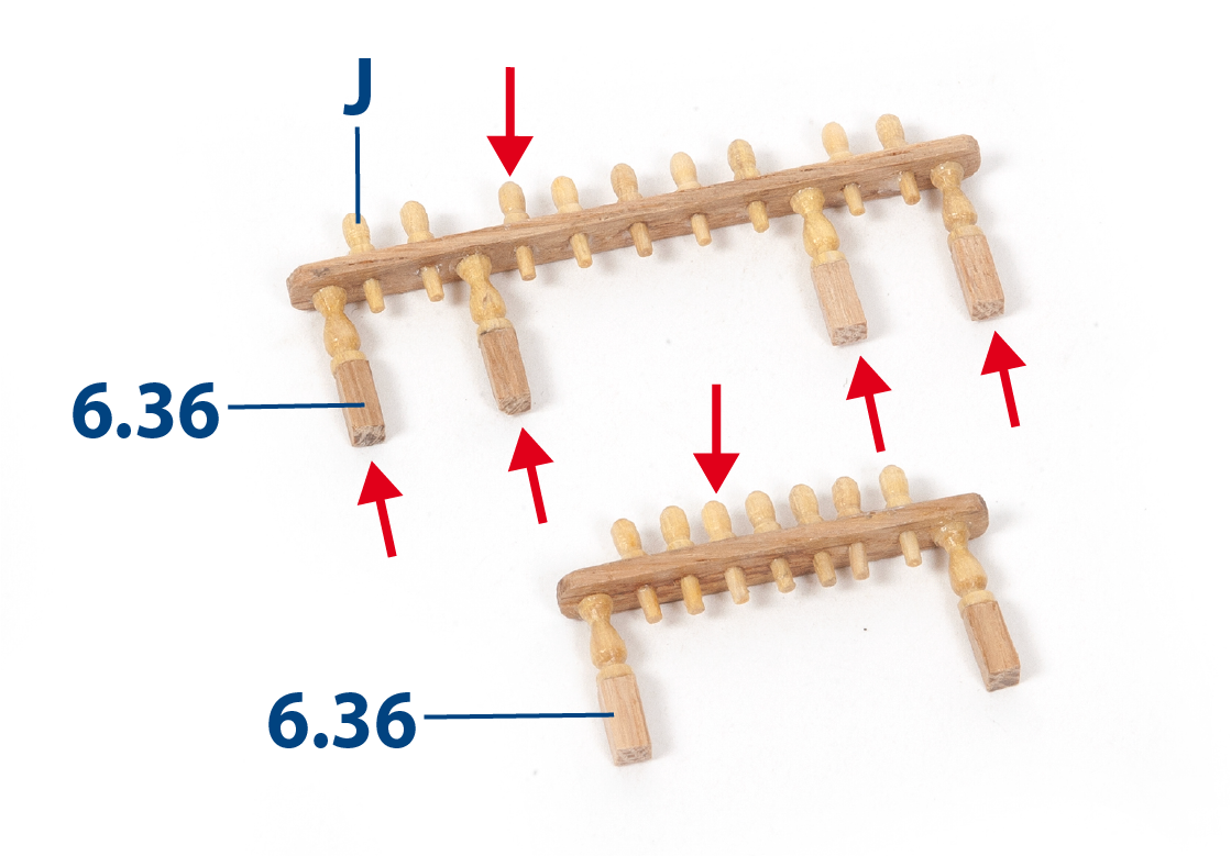
Step 13
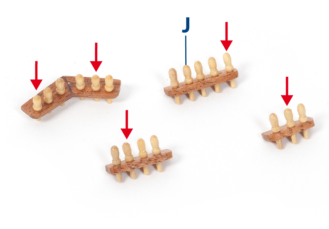
Insert and fix a pin J (supplied in pack 5) in each hole.
Step 14
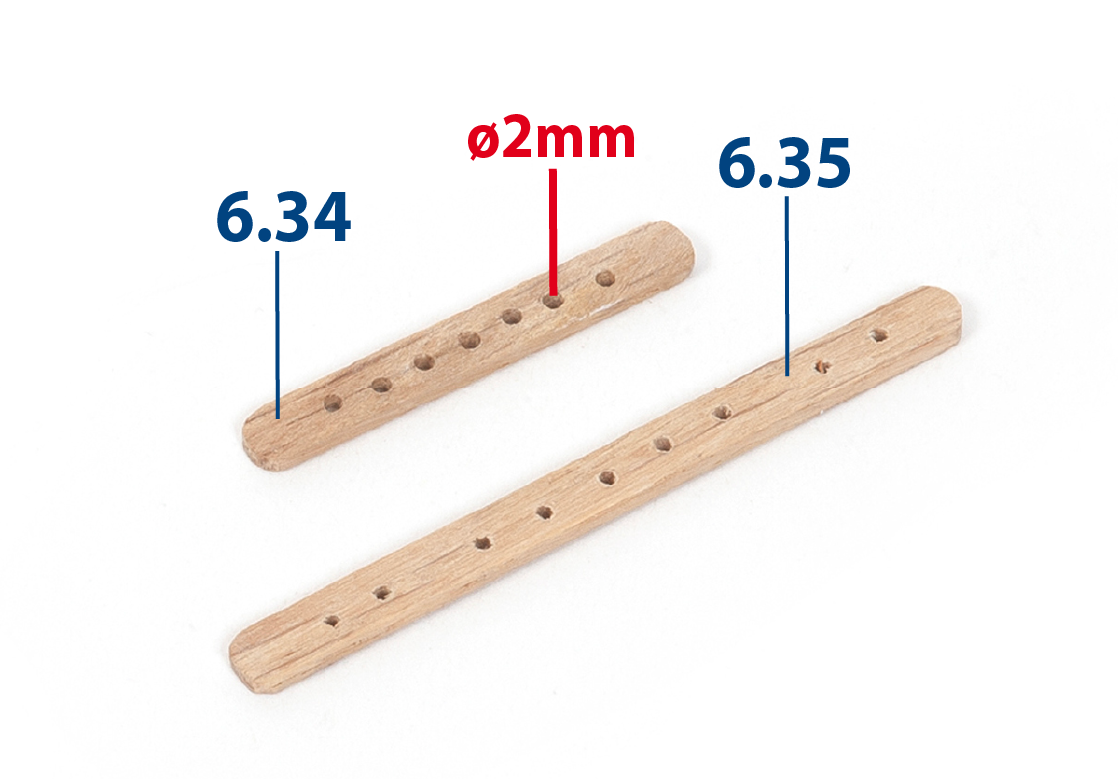
Make parts 6.34 and 6.35 with reference to the deck plan. Use 2 x 5 mm lime wood (supplied in pack 4).
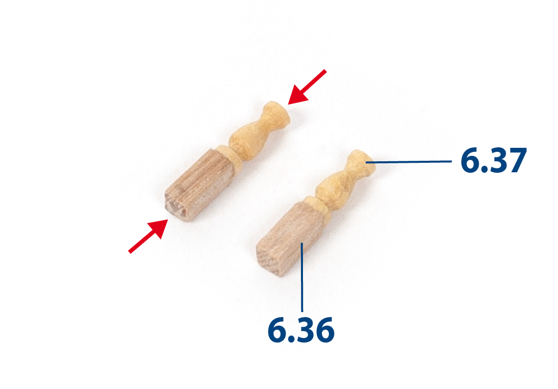
Step 15
Make ten pieces as shown in the picture. Use 3x3mm lime wood strips cut to appx. 7mm, and parts 6.37 supplied in pack 5.
Step 16
Build the pin rails as shown in the picture. Then varnish all the wooden parts.
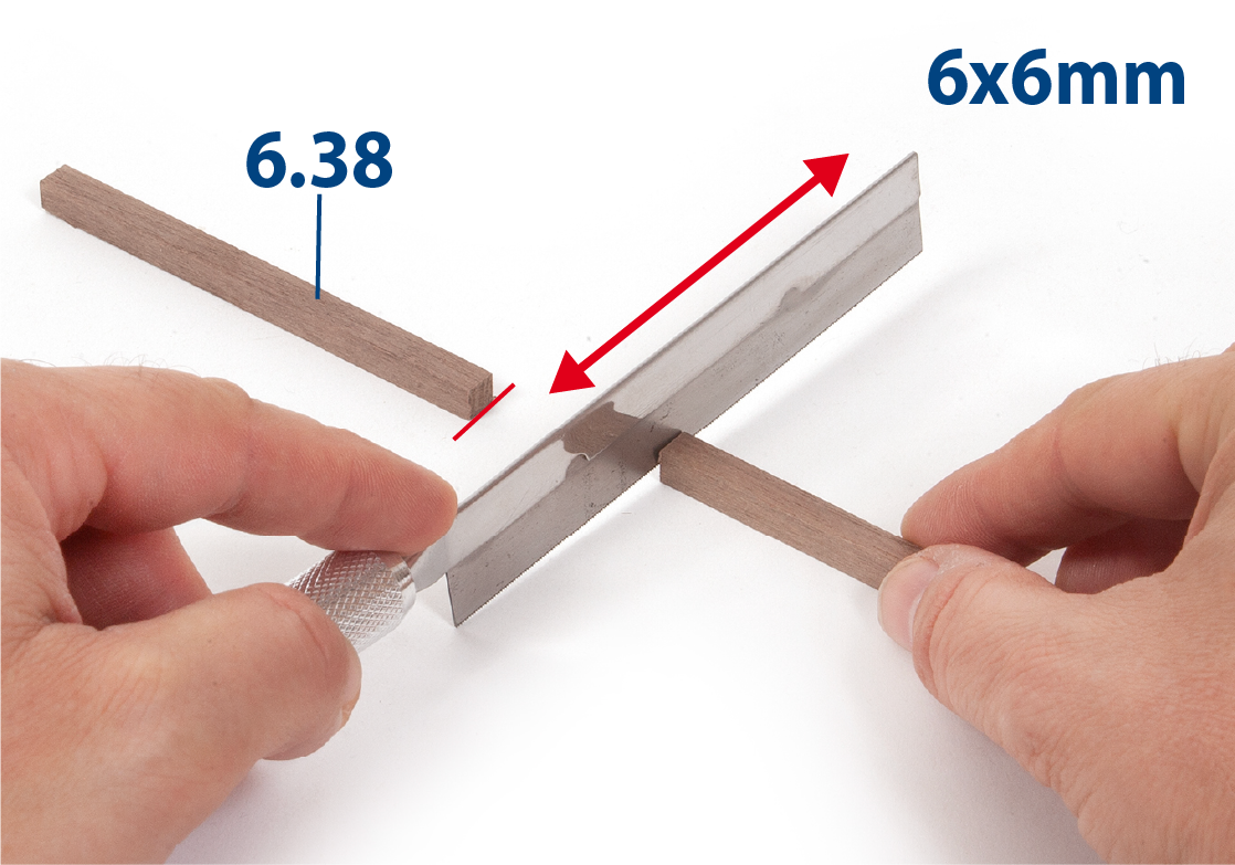
Step 1
Cut to size the pieces 6.38 (6 x 6 mm African walnut). These are to be used to make the anchor davits.
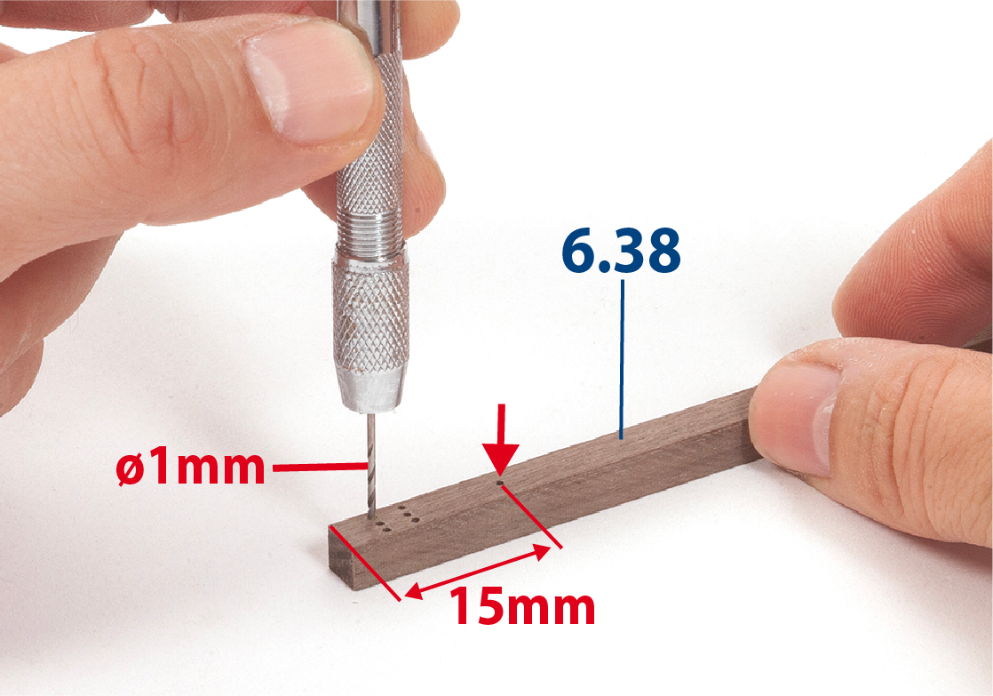
Step 2
Use a drill to drill the seven holes indicated in the picture in each piece.
Step 3
Polish a brass reinforcement strip 6.39 with a green scouring pad (used for cleaning kitchen utensils).
Step 4
Use flat nose pliers to shape the part 6.39.
Step 5
Fit and glue parts 6.39 to parts 6.38.
Step 6
In the picture you can see how the parts will look with the reinfrocement strips in place.
Step 7
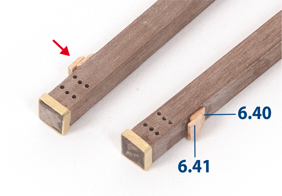
Cut parts 6.40 and 6.41 to the required dimensions (1 x 3 x 4 mm limewood), then glue them together and onto the davits, making sure they are symmetrical to form the two assemblies shown in the photo. Then sand both pieces down to 3 mm and smooth their edges.
Step 8
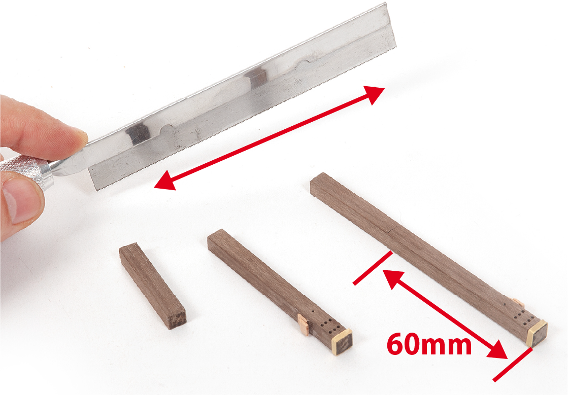
Cut the davits to size.
Step 9
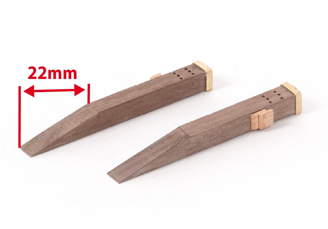
Then make a bevel as shown in the picture.
Step 10
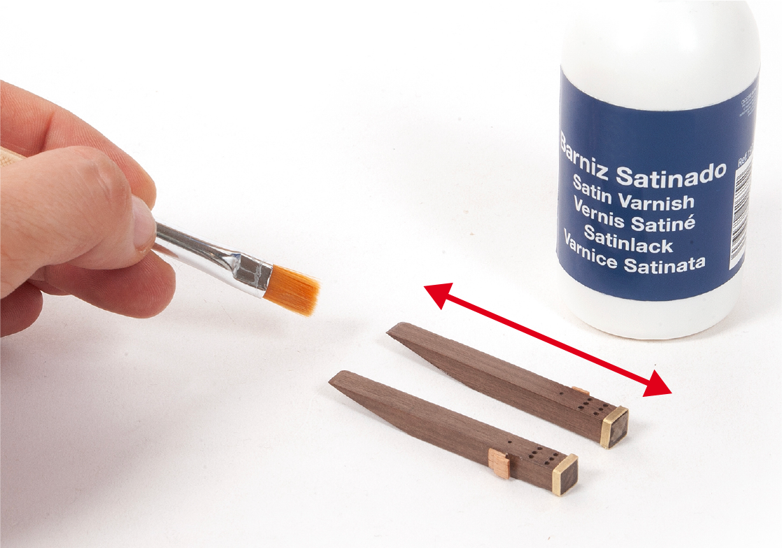
Apply varnish to the two davits.
Step 11
Drill holes to insert an eyebolt B with its ring H, and a point A in each davit. Then insert a point A into the upper part of each davit.
Step 12
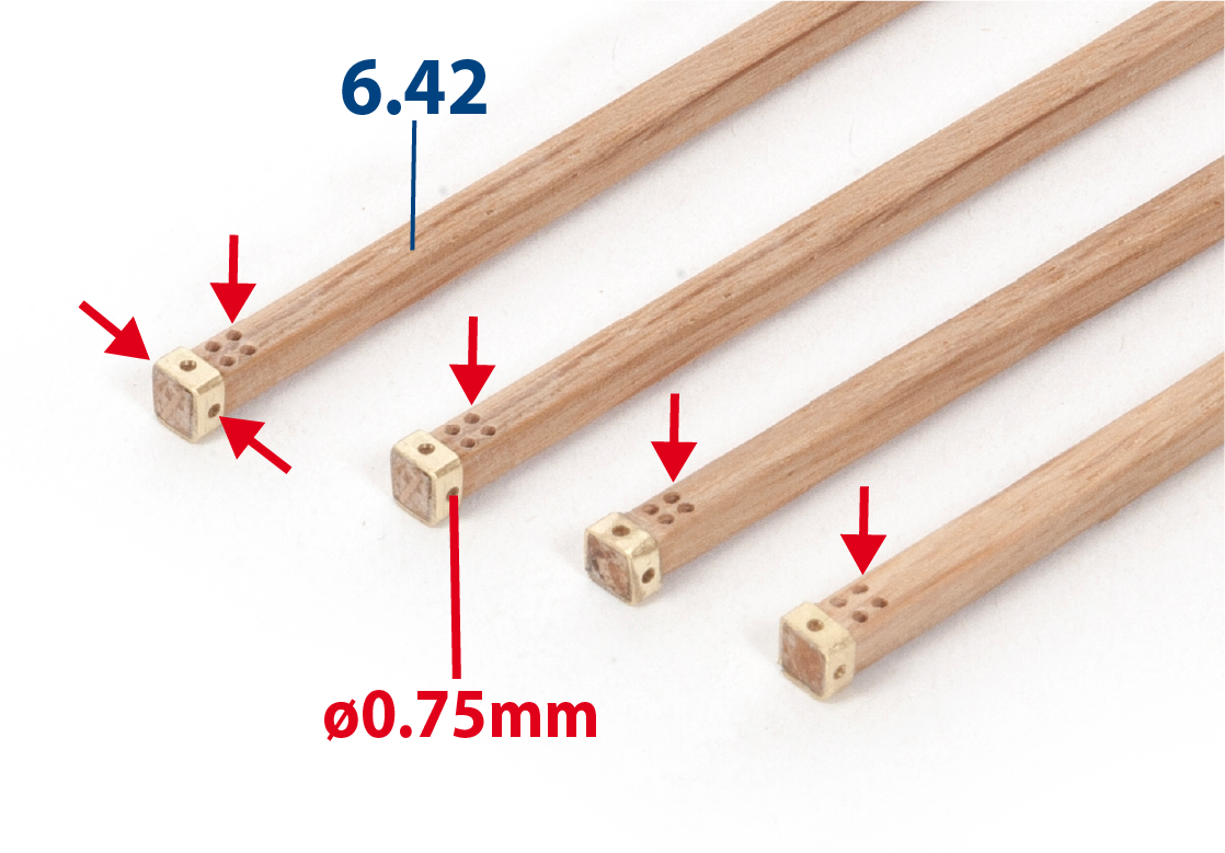
Cut to size the four pieces 6.42 (3 x 3 x 70 mm lime wood). These are to be used to make the davits for the boats.
Step 13
Bend brass reinforcement strip 6.43 to size.
Step 14
Fit and glue reinforcement strips 6.43 to the davits 6.42.
Step 15
Drill the holes indicated in the picture in each davit.
Step 16
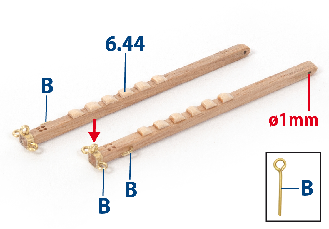
Make and fix the parts 6.44 and B as shown in the illustration. Round off the end of the davits and drill a ø1mm hole in them. Varnish the four completed davits.
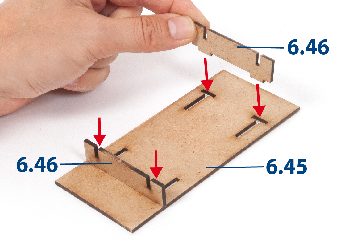
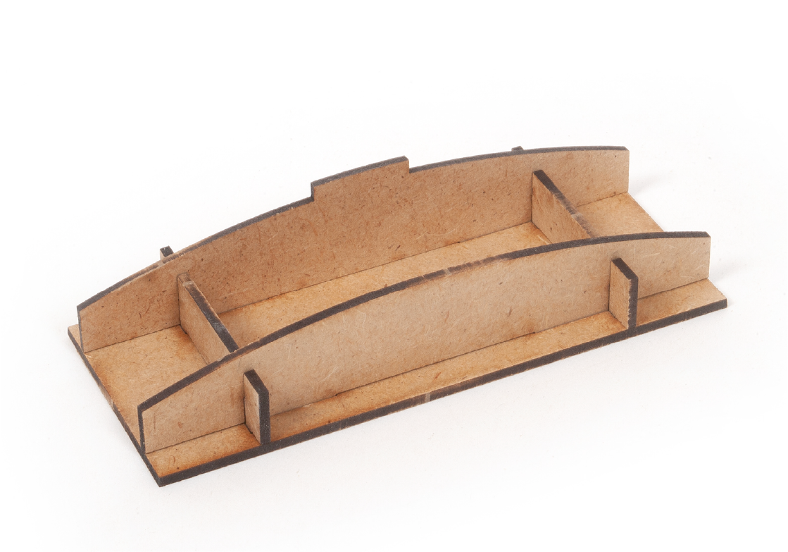
Step 1
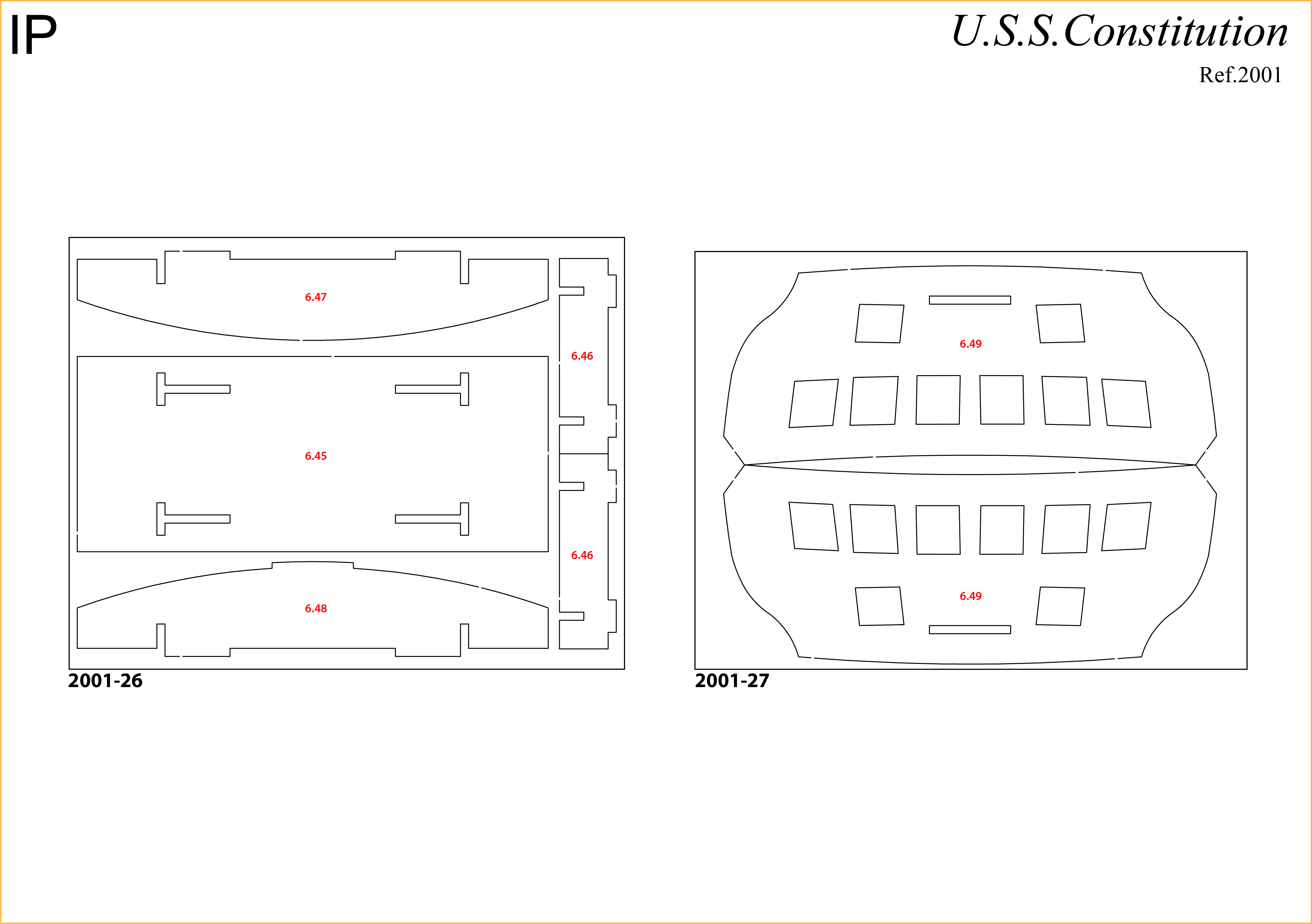
Insert and glue the parts 6.46 into the base 6.45.
Step 2
Then insert and glue the parts 6.47 and 6.48.
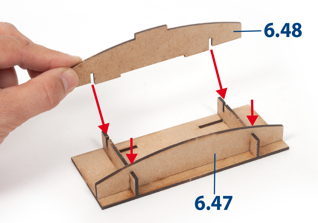
Step 3
This structure will serve as a template for bending the parts that will form the transom of the hull.
Step 4
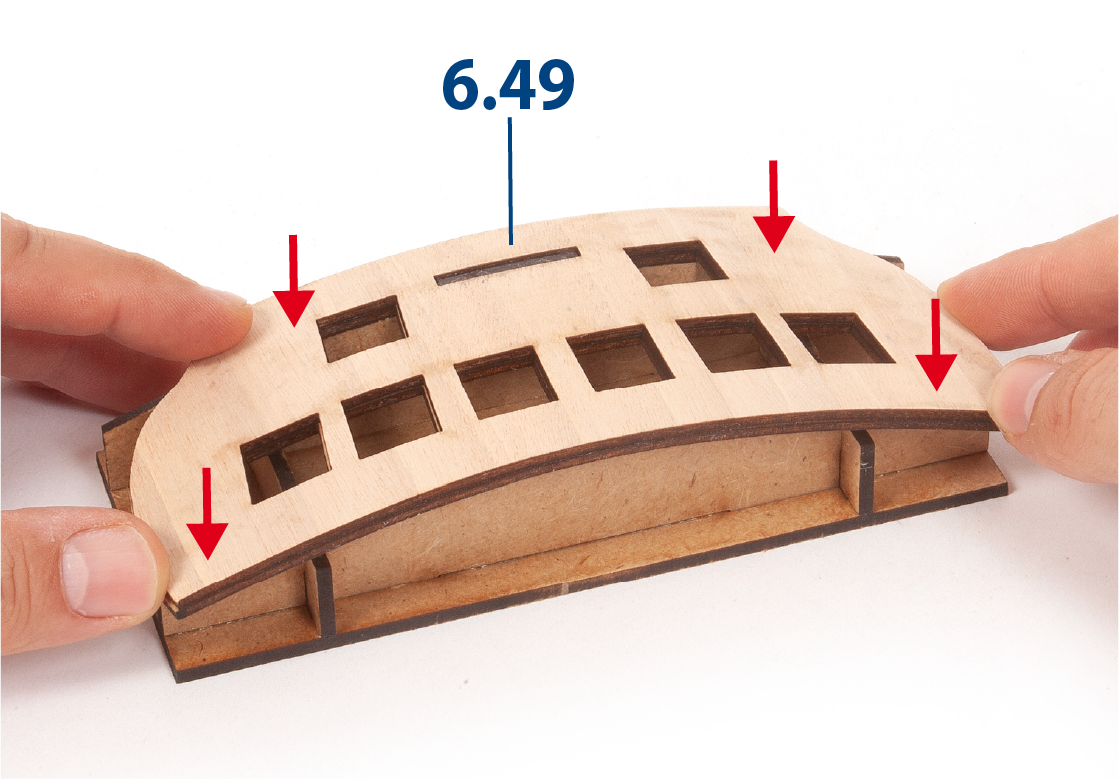
Sand one of the parts 6.49 and soak it in water for about 15 minutes.
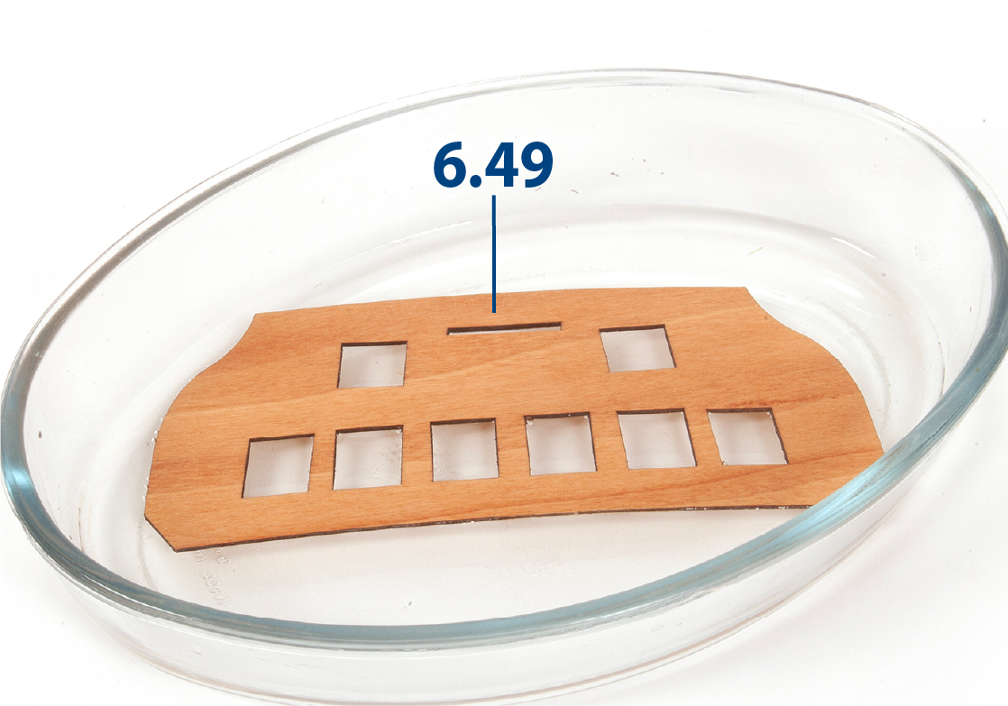
Step 5
Remove excess water with a blotting paper. Place part 6.49 on the jig to check its fit.
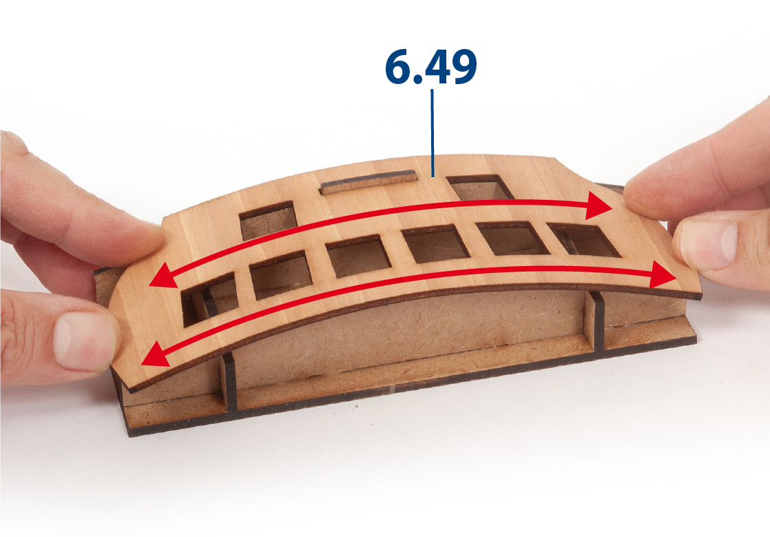
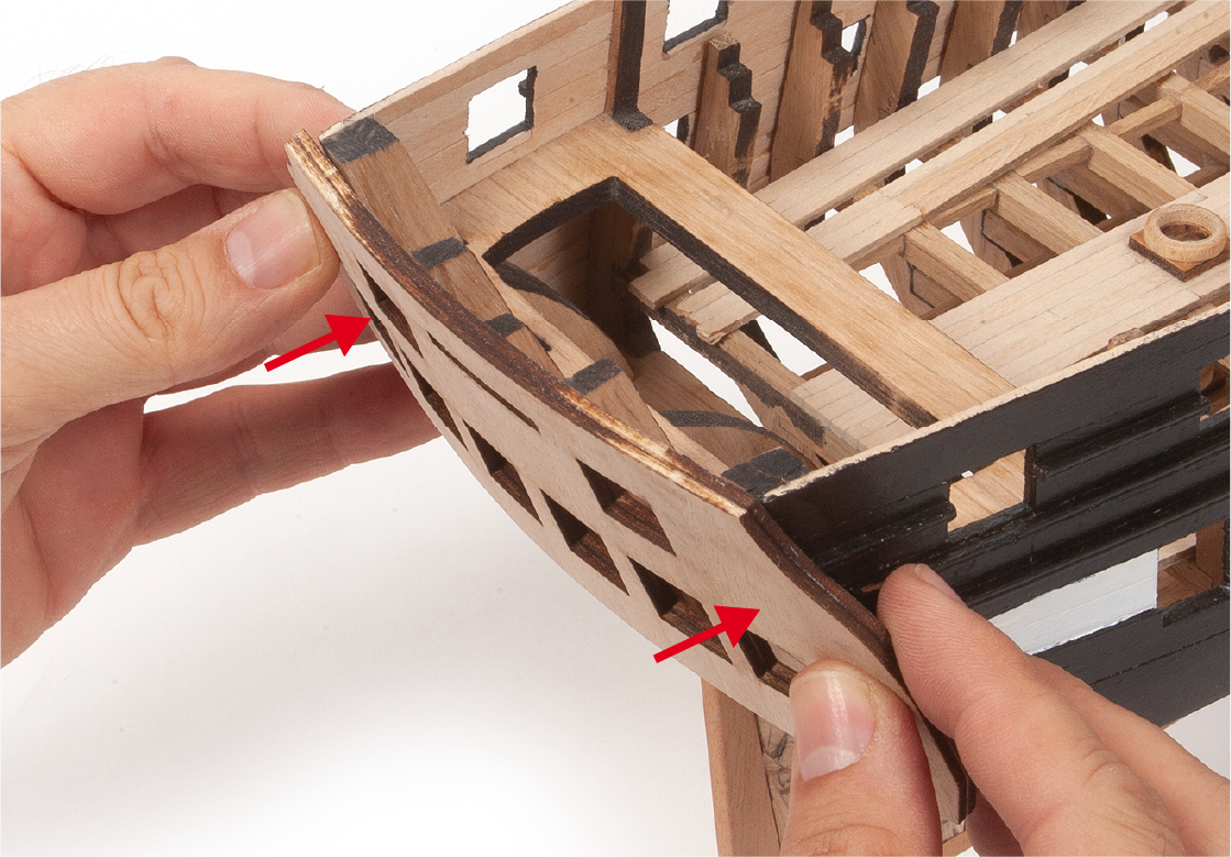
Step 6
Hold the piece in place with masking tape or tweezers. Leave it for a few hours until it dries and follows the curve of the template. You can speed up the process by applying heat with an iron or hot air gun.
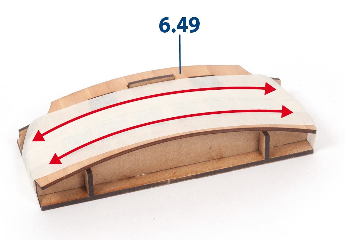
Step 7
Remove the masking tape and glue the other part 6.49, aligning the window holes of both parts. Hold the parts in place until the adhesive has dried.
Step 8
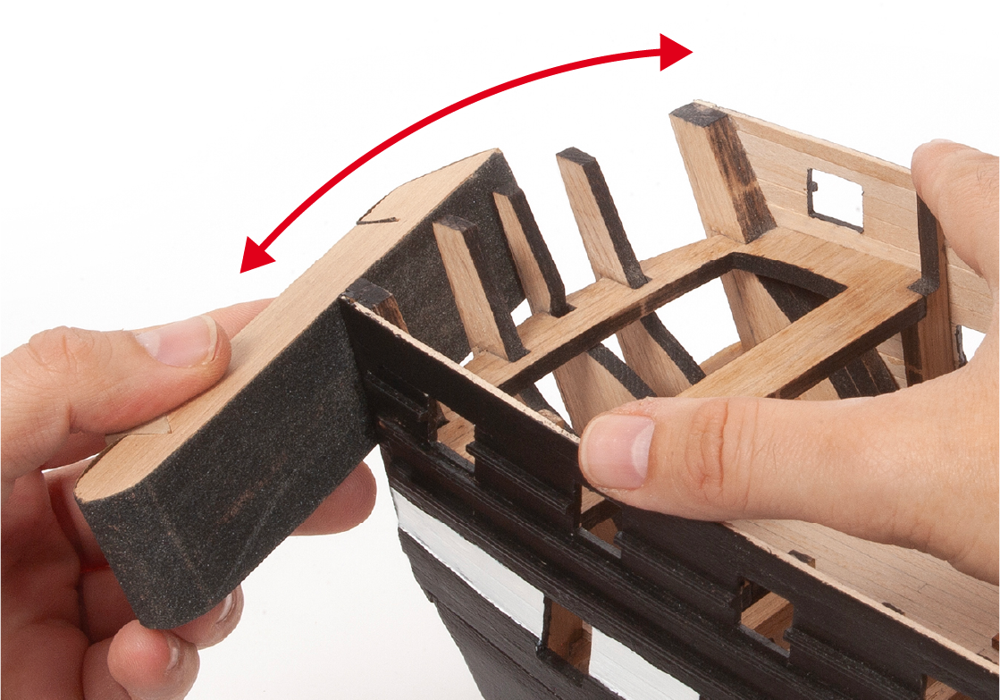
Present the transom at the stern of the hull to check its adjustment.
Step 9
The aft hull area must be sanded to allow the transom to fit.
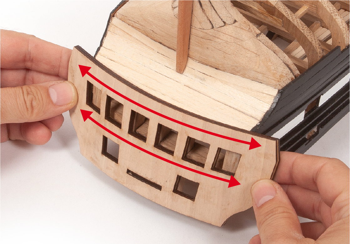
Step 10
Reposition the transom on the hull to ensure it fits properly. Separate the transom from the hull and set it aside for later use.
Step 11
This is what the hull will look like at this stage of construction.