Pack 7
BUILD INSTRUCTIONS
Instructions for building your USS Constitution model ship
Your model of the USS Constitution is divided into 12 packs.
You will need to follow the step-by-step assembly photos, the plans and the explanatory texts below.
Please save the leftover materials from each pack for use when instructed to do so at a later stage of the assembly instructions.
The IP sheets displayed below are drawings of laser-cut parts and photo-etched brass parts and will serve as a guide for identification of some parts.
Use the PARTS REFERENCE table to help locate the parts.
The PL-00 templates (printed at 1/1 scale) included in each pack will serve as a guide for building the model.
Please check the list below to ensure you have all the tools required for building your wooden ship.
When removing a part, cut the ribs that join the part to the wooden plate with a cutter.
Remove the parts carefully so as not to break them.
Keep and store the parts in their frames. Only remove the parts you are working on in each step.
Extra support can be found on our forum or from the Expert Directory page of our website.
PARTS LIST
| Material | Quantity | |
| Boards 2001-29 – 2001-33 | Wood | 5 |
| Rudder hinge | 10 | |
| Brass wire (ø 1.5 x 100 mm) | 5 | |
| Block (4 mm) | 150 | |
| Brass wire (ø 0.5 x 100 mm) | 60 | |
| Horn timber | 3 | |
| Inclined horn timber | 1 | |
| Gunport cornice | 30 | |
| Supports | 2 | |
| Display stand | 1 |
Tools you will need: cutting mat, pencil, cutting knife, fine-grit sandpaper or sponge sandpaper, file, white wood glue, super glue (cyanoacrylate glue), masking tape, set square, hacksaw, sanding block, 30 cm steel ruler, clamps, drill, moulding scriber tool
PACK 07 IDENTIFICATION SHEETS
PARTS REFERENCE
PART NO. | IP-SHEET LOCATION | PART NO. | IP-SHEET LOCATION | PART NO. | IP-SHEET LOCATION |
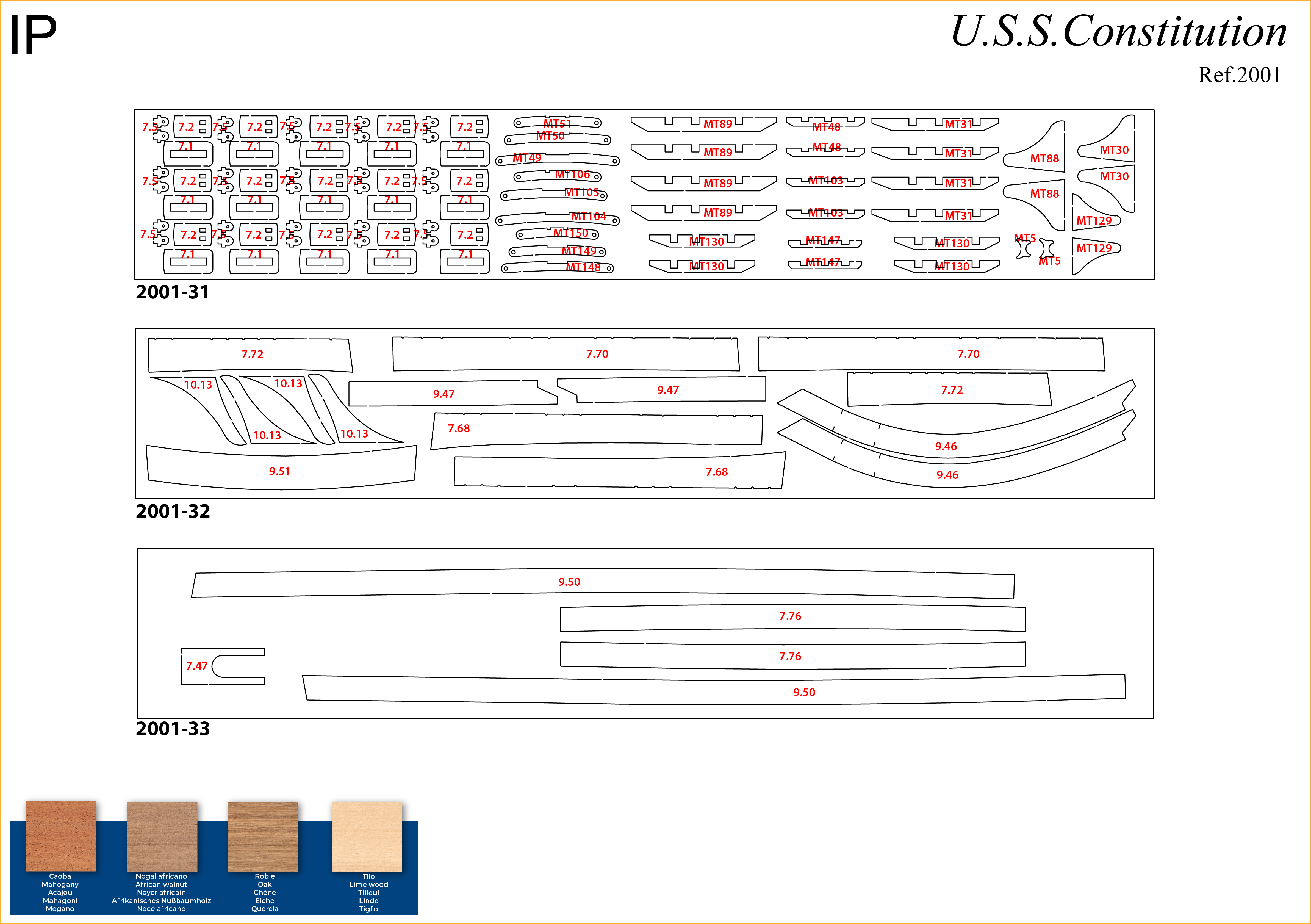
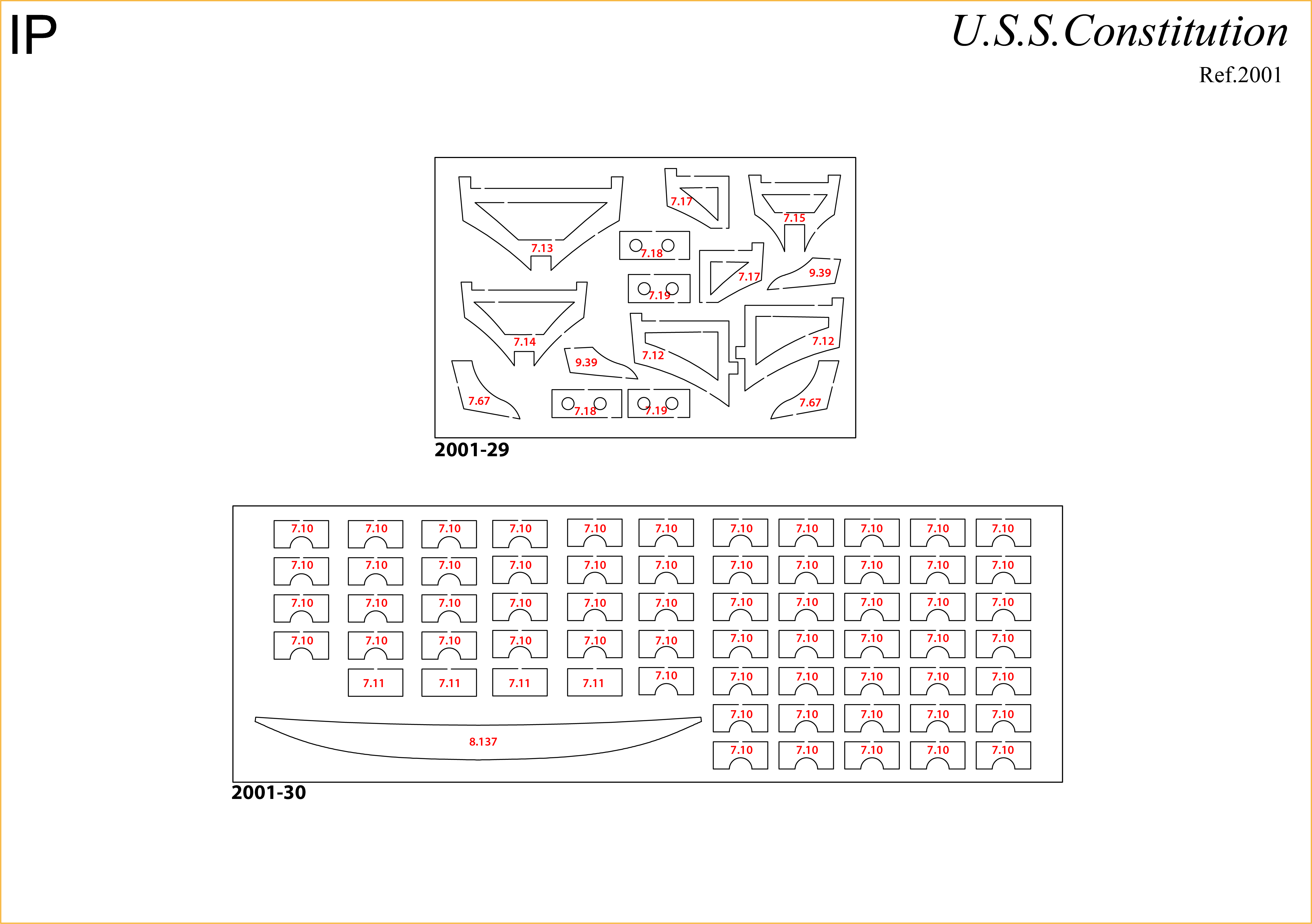
| 7.1 | 2001-31 | 7.13 | 2001-29 | 7.52 | 2001-11 |
| 7.2 | 2001-31 | 7.14 | 2001-29 | 7.53 | 2001-11 |
| 7.5 | 2001-31 | 7.15 | 2001-29 | 7.67 | 2001-29 |
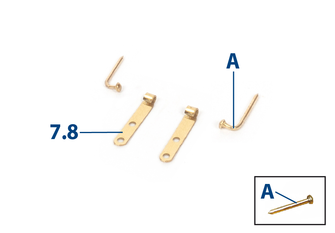
| 7.8 | 2001-38 | 7.16 | 2001-11 | 7.68 | 2001-32 |
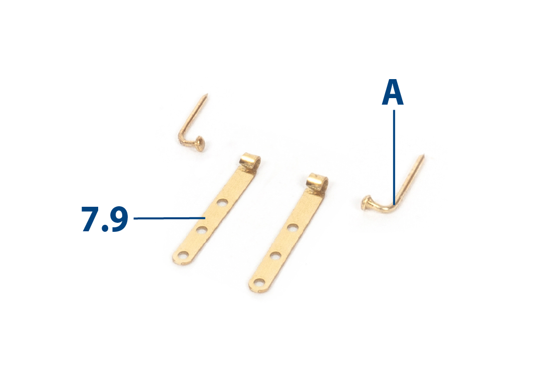
| 7.9 | 2001-38 | 7.17 | 2001-29 | 7.70 | 2001-32 |
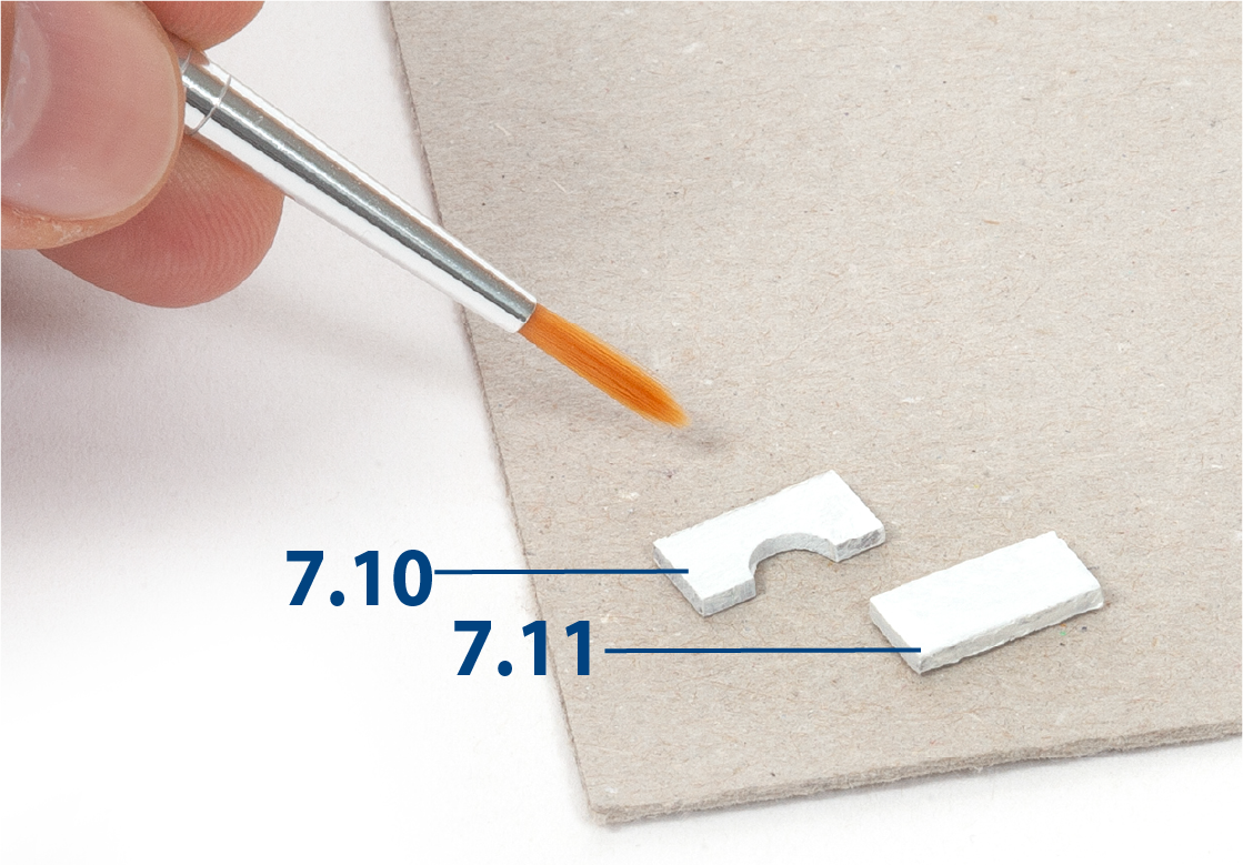
| 7.10 | 2001-30 | 7.18 | 2001-29 | 7.72 | 2001-32 |
| 7.11 | 2001-30 | 7.19 | 2001-29 | 7.76 | 2001-33 |
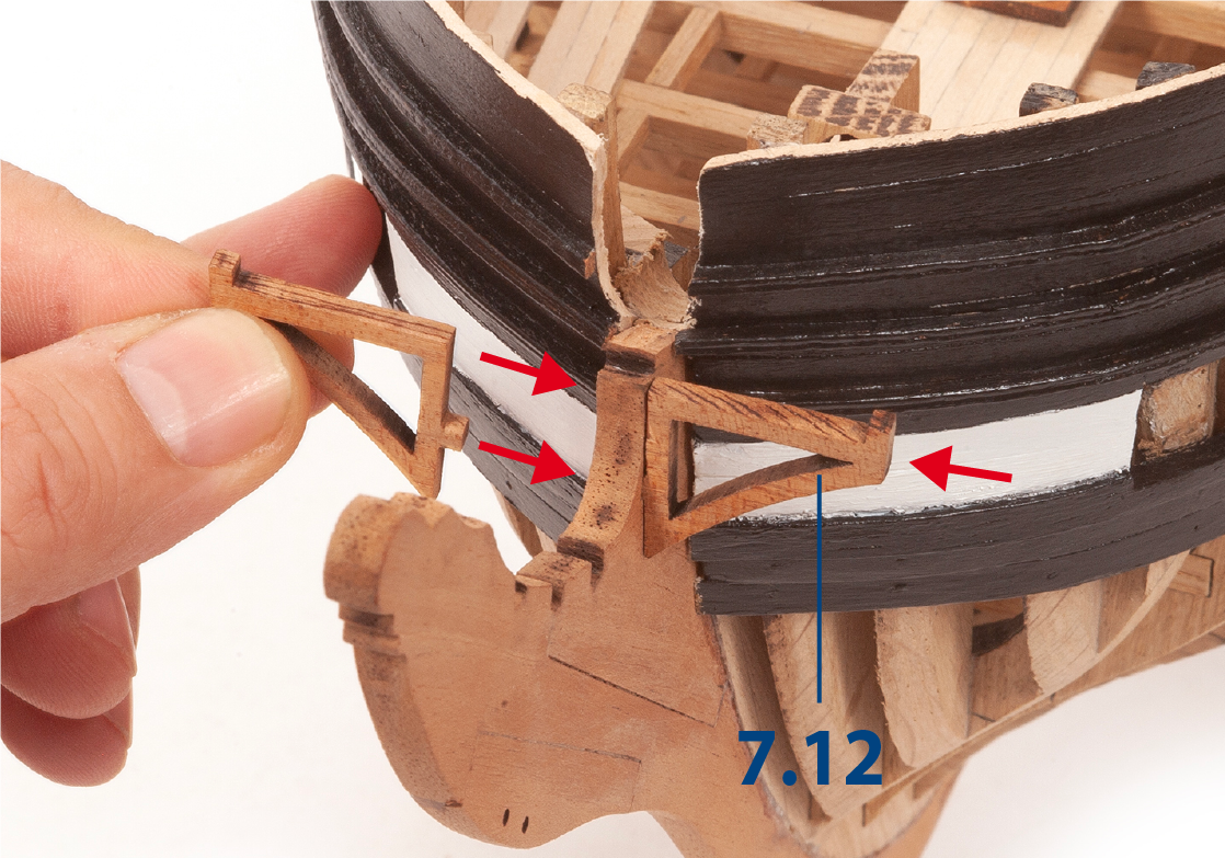
| 7.12 | 2001-29 | 7.47 | 2001-33 |
Step 1
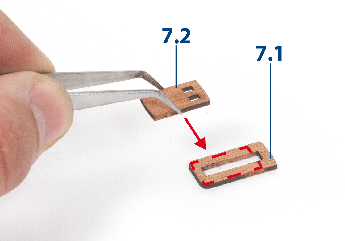
Sand parts 7.1 and 7.2 and glue them together as shown in the picture.
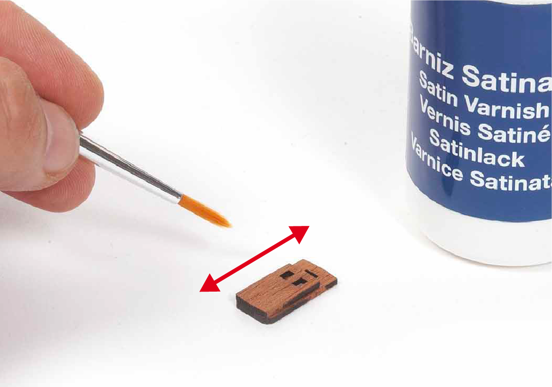
Step 2
Repeat to build 15 carronade bases. Apply varnish to all the carronade bases.
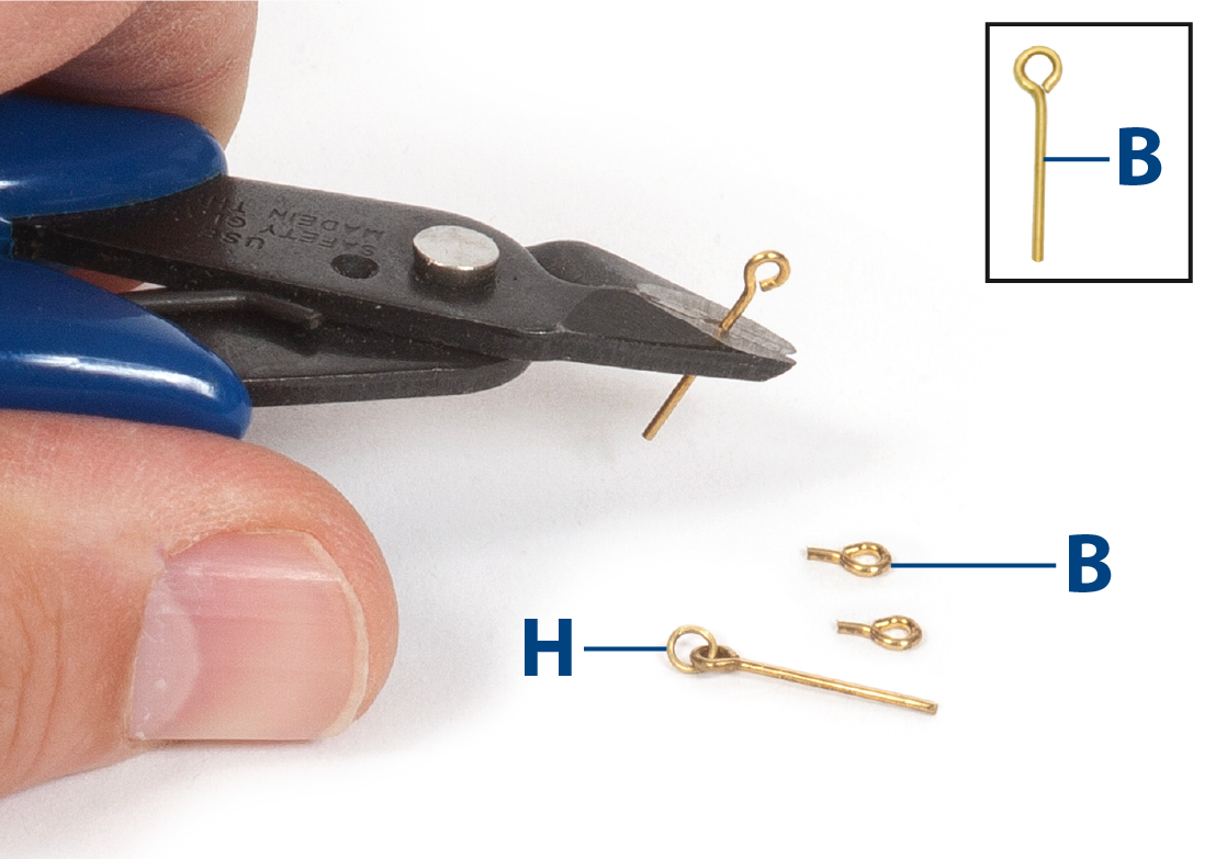
Step 3
Use pliers to open, close, and to cut the eyebolts B and the rings H (ø 3mm), supplied with pack 5.
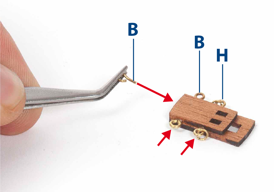
Step 4
Drill holes in the carronade bases and insert and glue the parts shown in the picture.
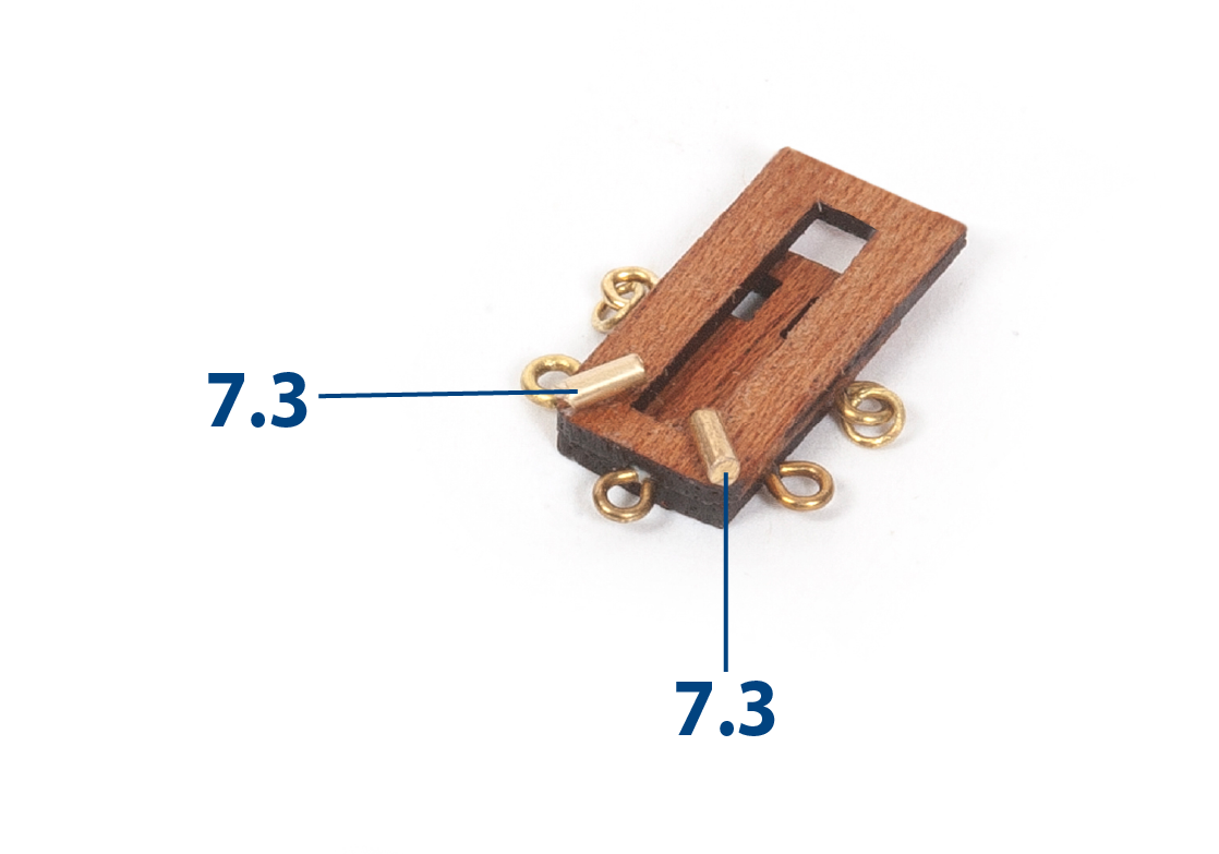
Step 5
Cut to length and glue parts 7.3 (ø 1.5 x 3 mm) to the carronade bases.
Step 6
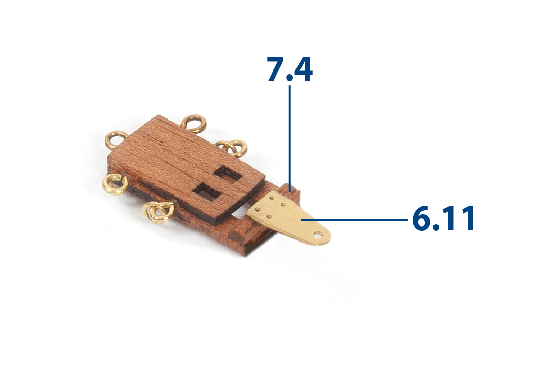
Cut parts 7.4 to length (2 x 2 x 10 mm mahogany, supplied in pack 5). Glue parts 7.4 and 6.11 (supplied in pack 4) as shown.
Step 7
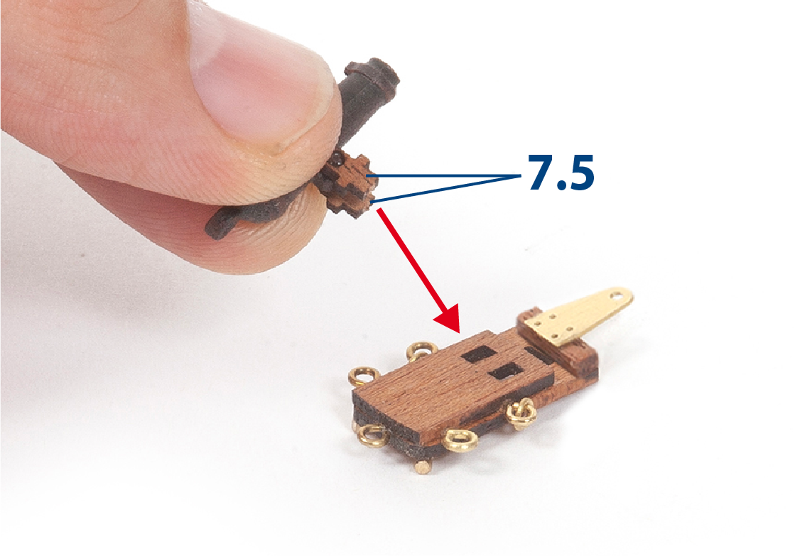
Glue parts 7.5 into the carronade bases.
Step 8
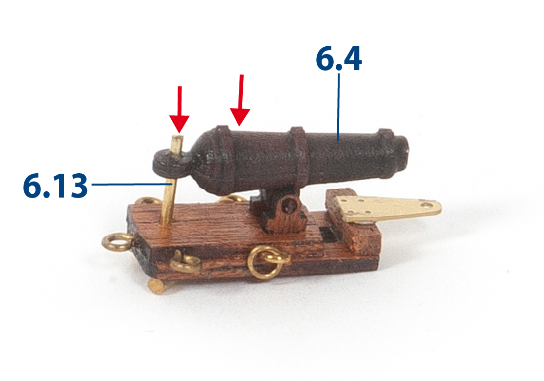
Make and glue the axles 6.13 (ø 1 x 10 mm, supplied in pack 5). In total you should be able to build 15 complete carronades.
Step 9
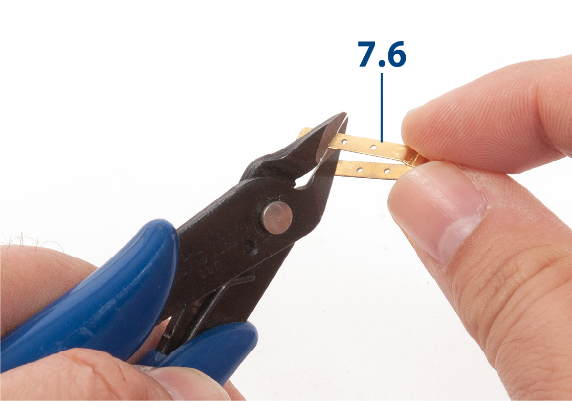
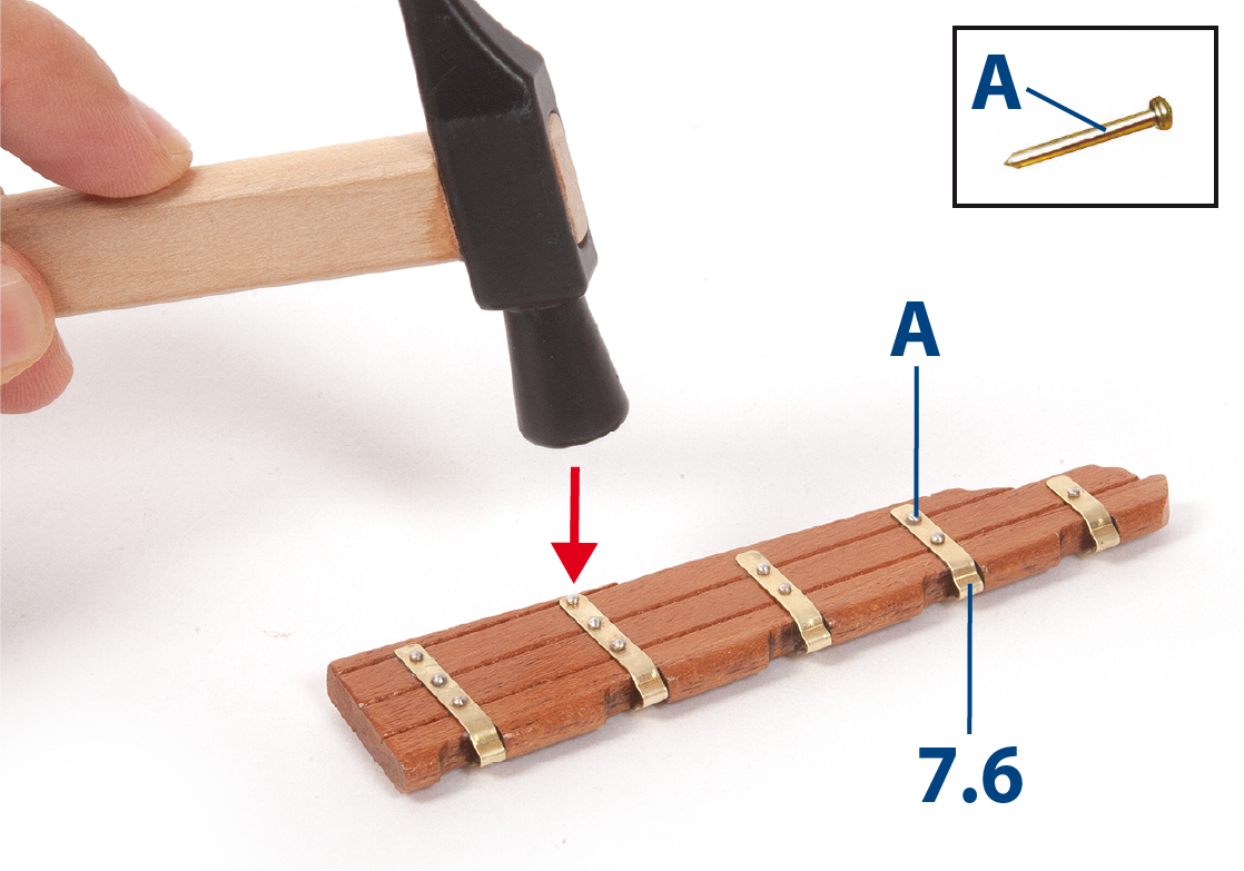
Adjust the length of the rudder hinges 7.6 as required. Use the elevation drawing as a reference.
Step 10
Fit the hinges 7.6 to the rudder blade (pack 6 stage 30) and secure them with nails A (supplied with pack 4). Shorten the nails before fitting them.
Step 11
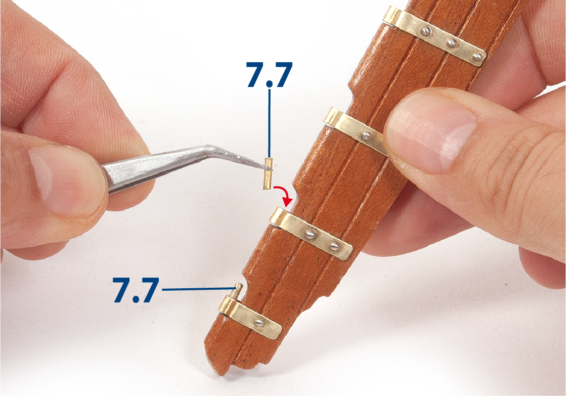
Cut to length and fix the axles 7.7 (ø 1.5 x 5 mm) on the inside of the hinges.
Step 12
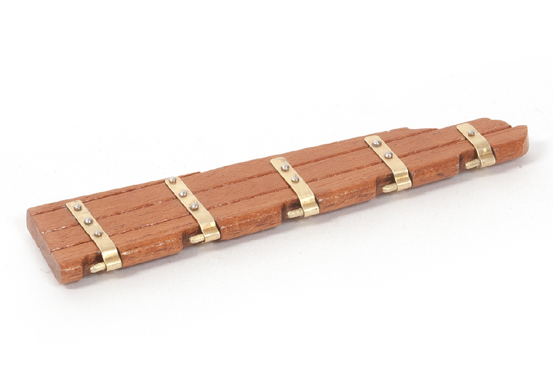
Note the rudder blade with hinges and shafts in place. Keep aside for later use.
Step 13
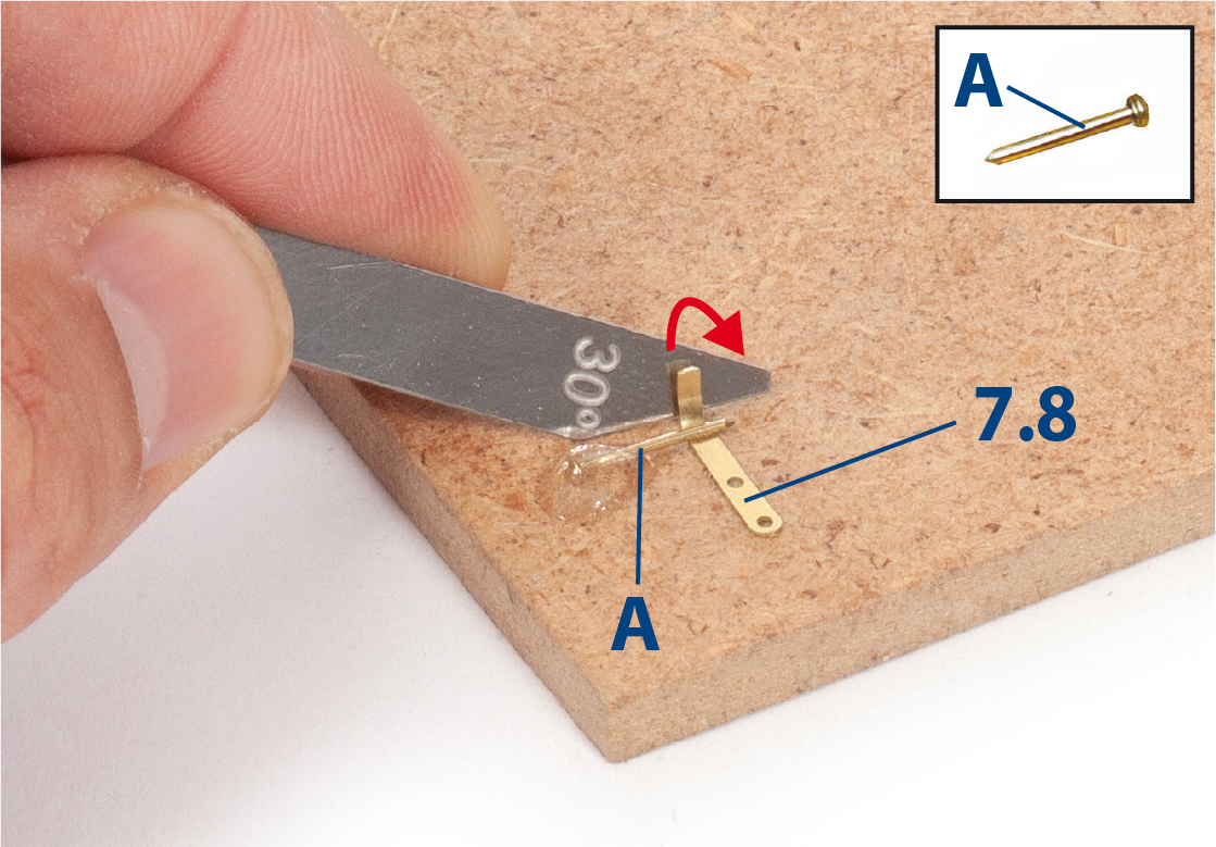
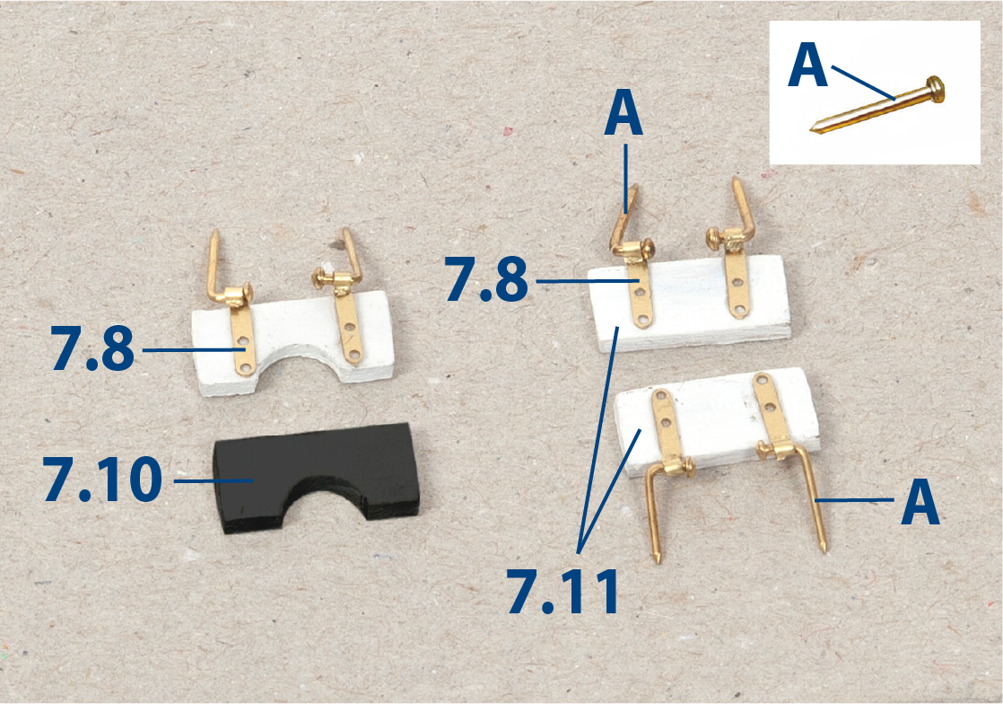
Curl the hinges 7.8 and 7.9 (supplied in pack 4). A jig can be made by gluing a nail to a block of wood as shown.
Step 14
Bend the tips of nails A for hinges 7.8 and 7.9 (supplied in pack 4).
Step 15
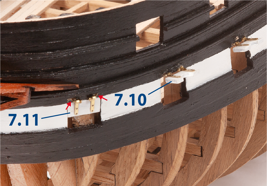
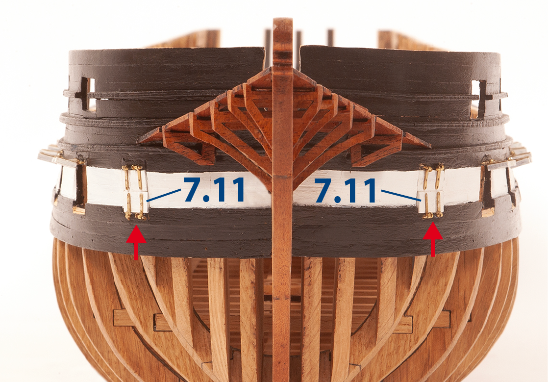
Sand and paint the gunport lids 7.10 and 7.11 with white paint. The lower lids 7.10 should be painted black. Refer to the pictures in stage 34, steps 13– 16 for extra guidance.
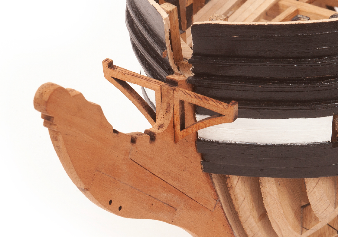
Step 1
Fit and glue parts 7.12.
Step 2
Note that both parts must be aligned, as shown in the picture.
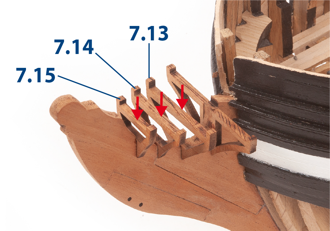
Step 3
Fit and glue parts 7.13 to 7.15.
Step 4
Fit and glue the parts 7.16 (supplied in pack 2).
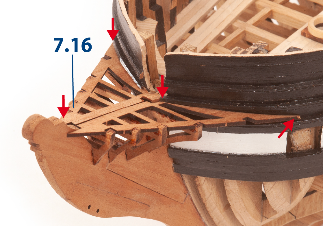
Step 5
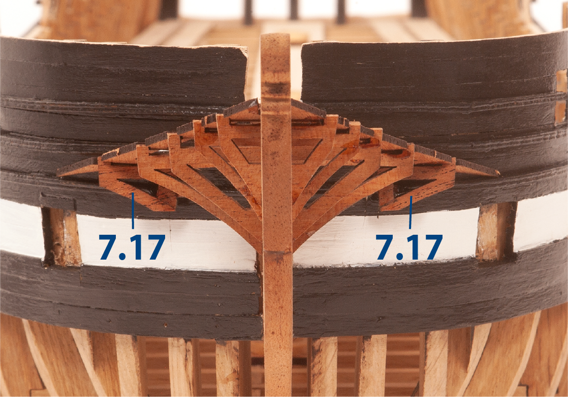
Bevel parts 7.17 and glue one on each side of the hull.
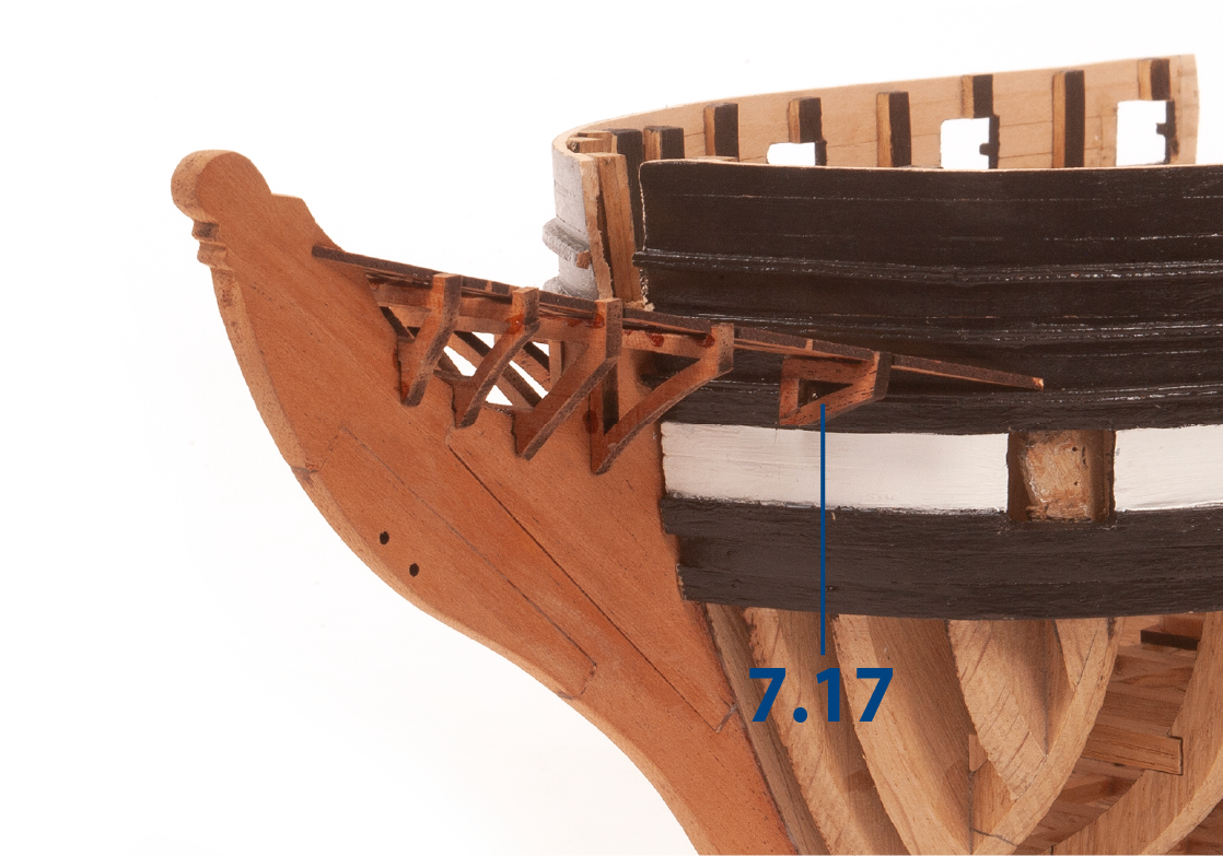
Step 6
In this picture you can see the parts from another angle.
Step 7
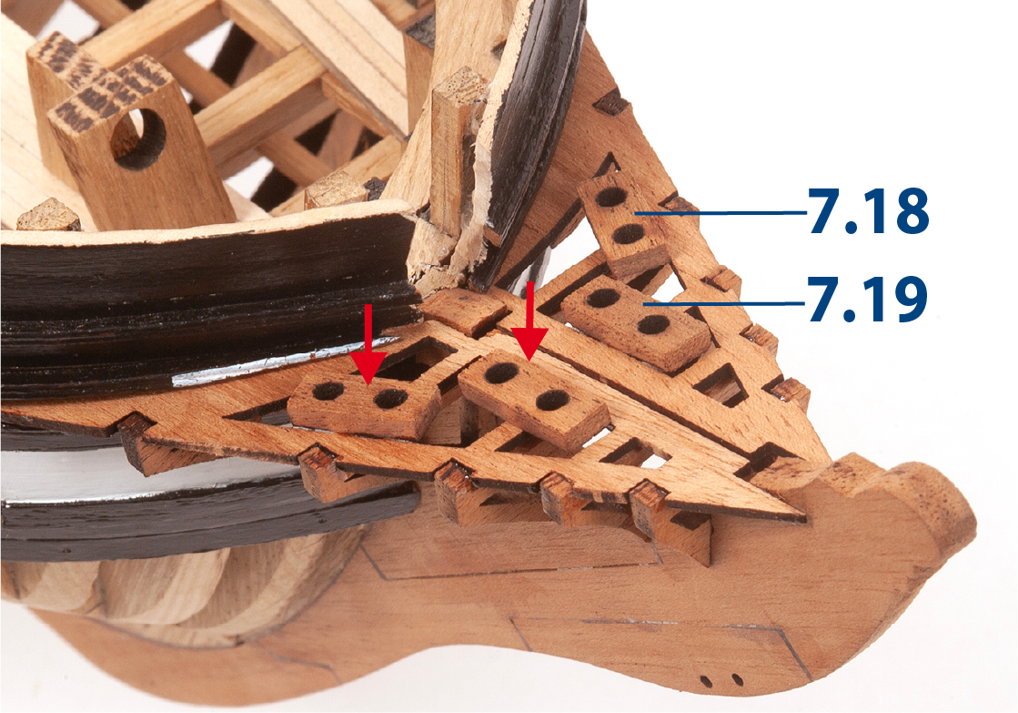
Glue parts 7.18 and 7.19.
Step 8
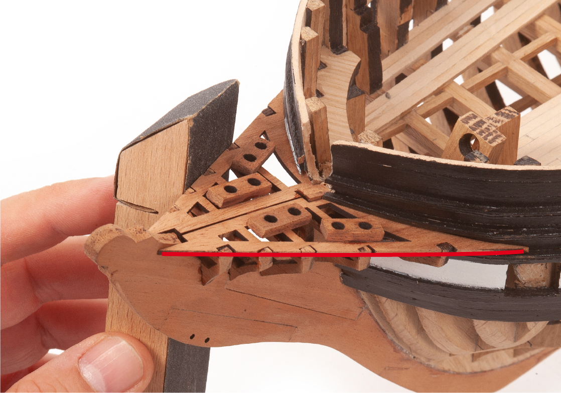
Use a sanding block to even out the edges.
Step 9
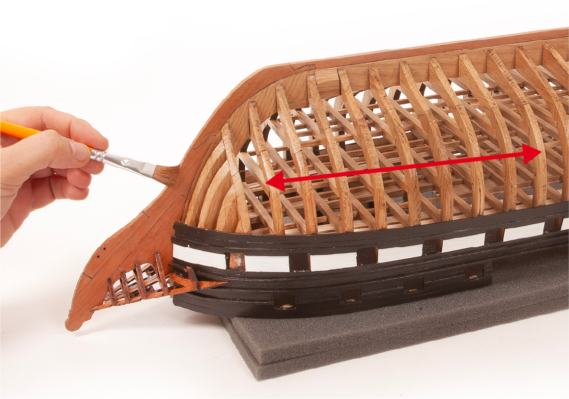
Varnish the entire underside of the hull and the pieces of wood that have been added to the bow.
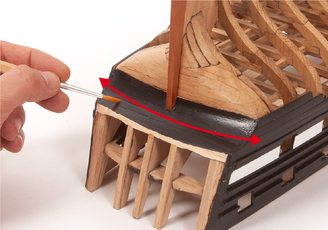
Step 10
Sand the aft area shown in the picture and paint it black.
Step 11
Fit and glue the hinges to the lids and insert a nail into each hinge.
Step 12
Drill two holes above each gunport to fit the lids. Refer to the elevation drawing to fit the parts.
Step 13
Fit the upper lids as shown in the picture.
Step 14
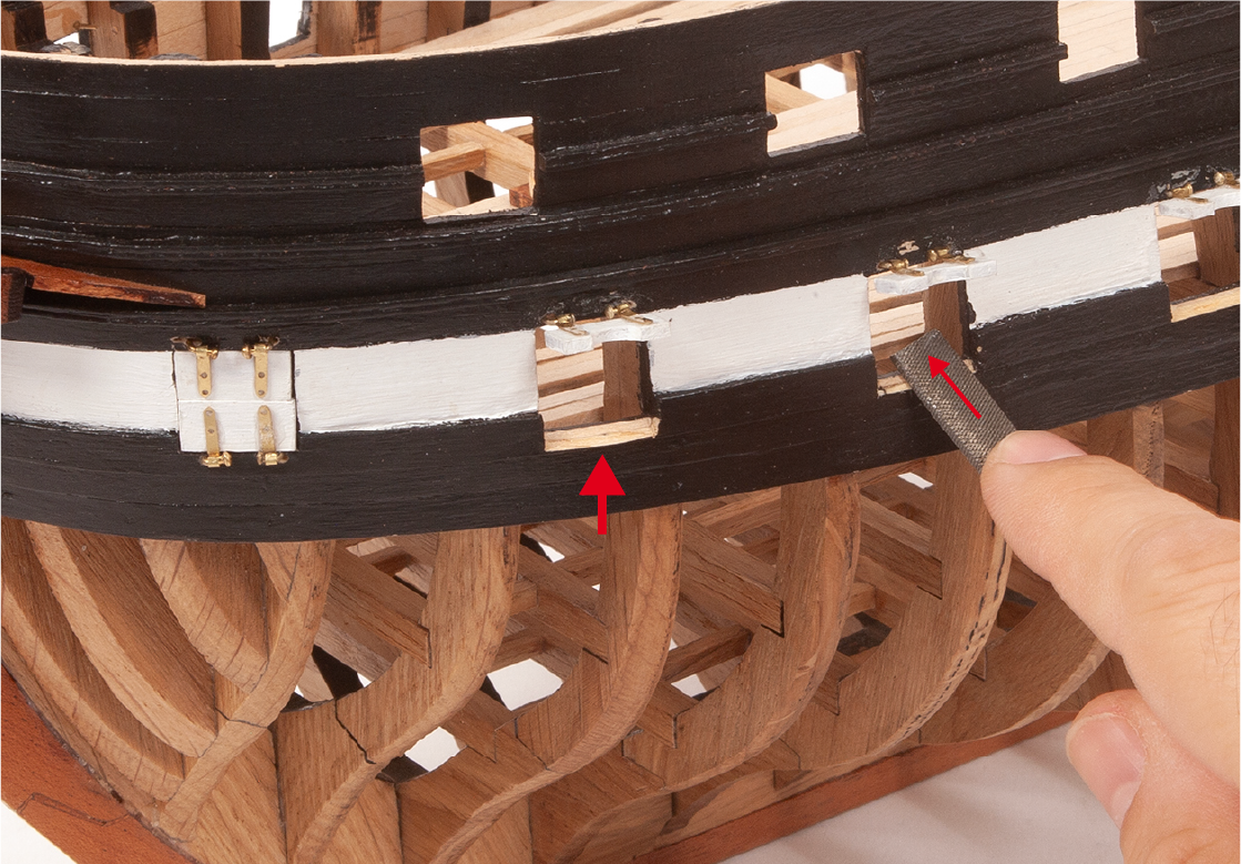
Fit the lower lids at the front of the hull as shown.
Step 15
Using a file, chamfer the bottom edge of the lower gunports to allow the lower lids to be fitted.
Step 16
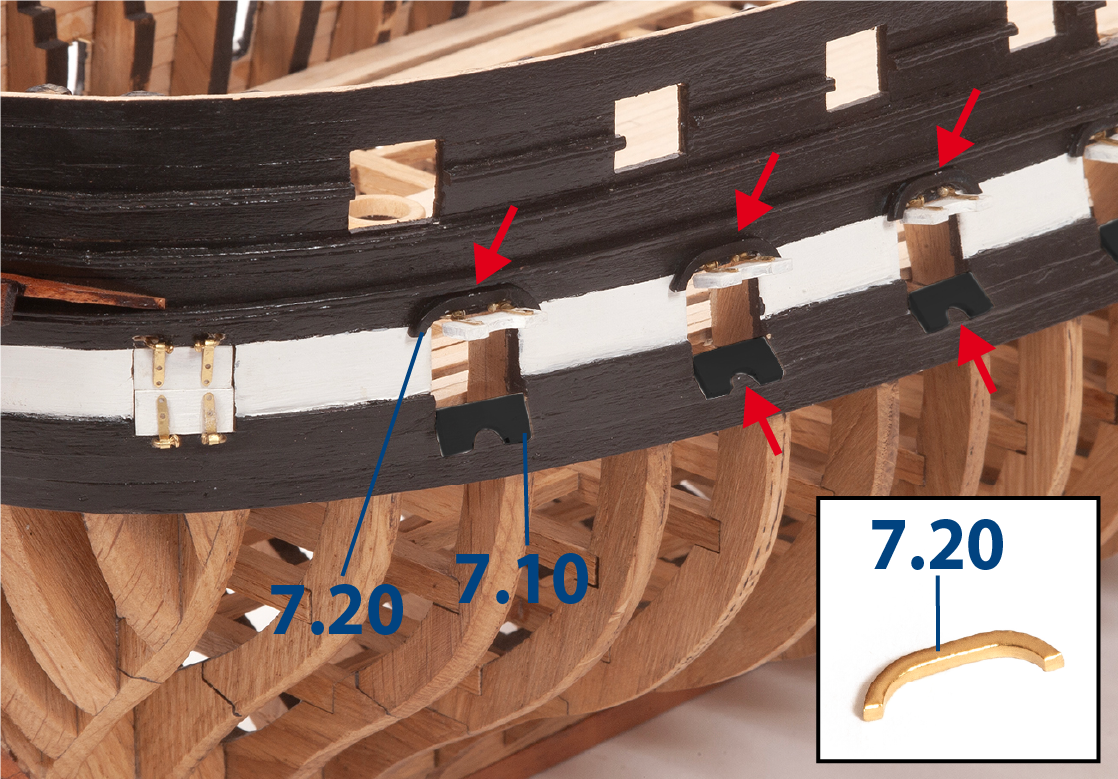
Fix the lower lids. Then, paint the parts 7.20 black and fit them as shown in the picture.
Step 1
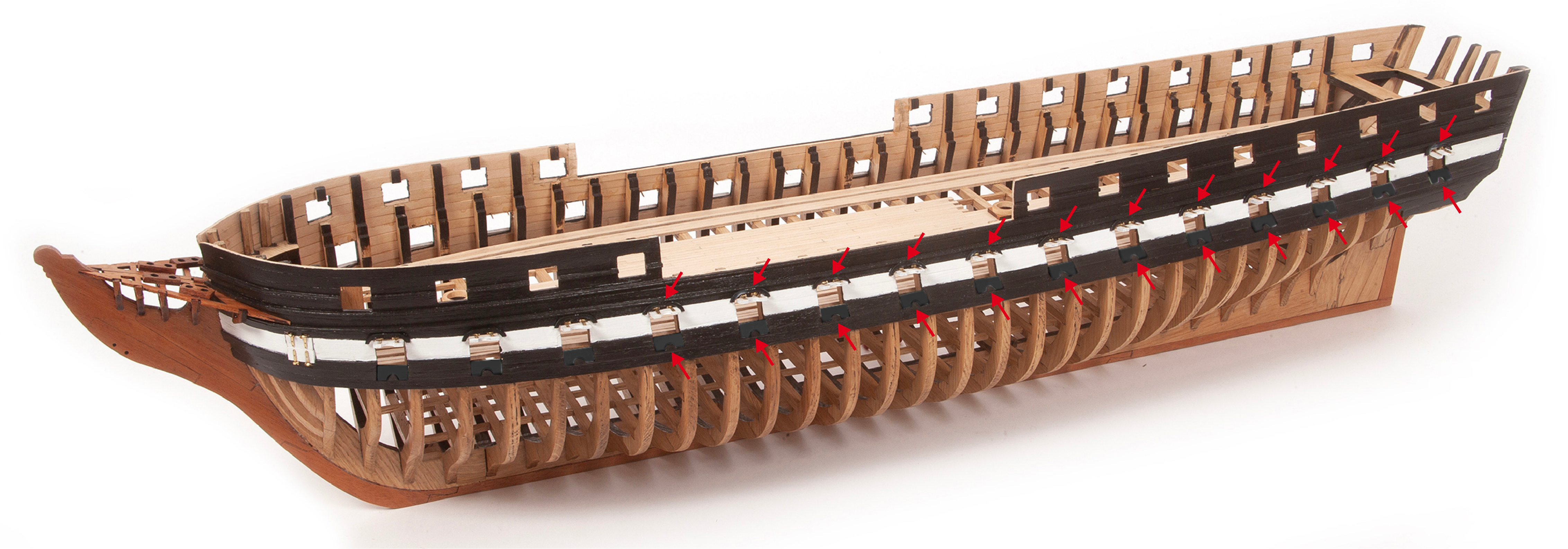
Glue the remaining parts 7.10 and 7.20 to the lower gunports on both sides of the hull.
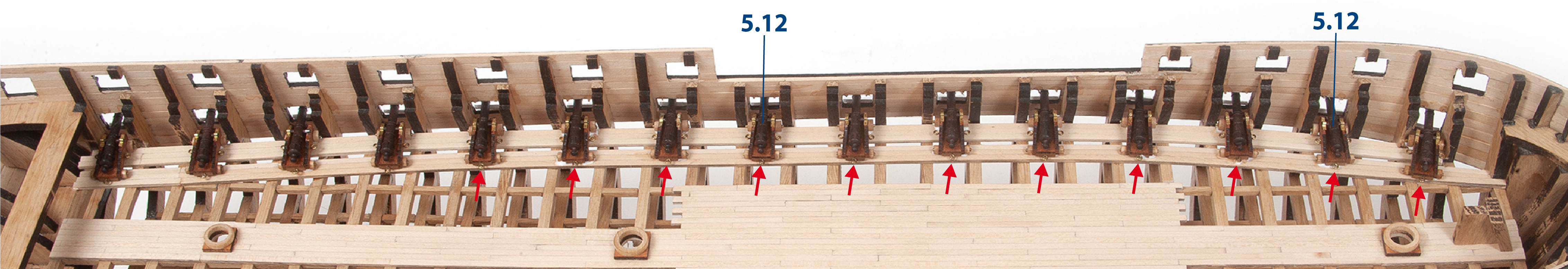
Step 2
Check the fit of the barrels through the lower gunports. These barrels are the longer 5.12 type.
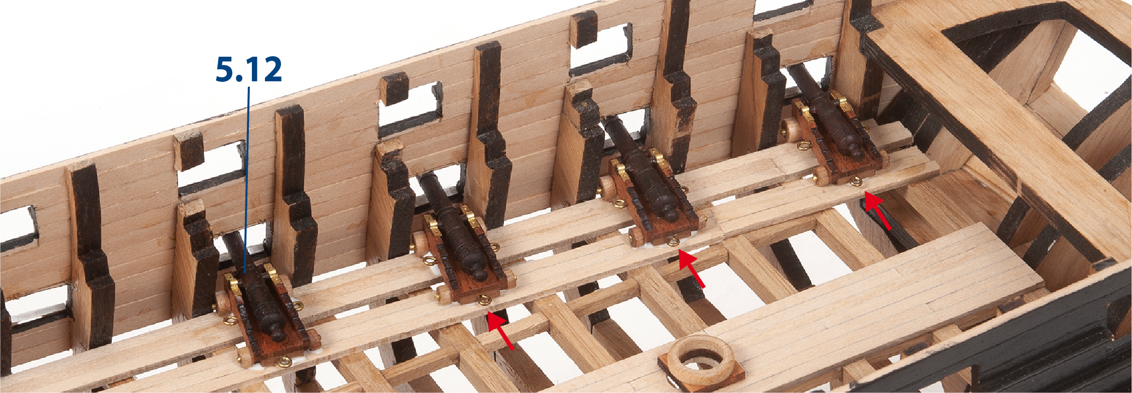
Step 3
Note that the barrels should protrude approximately 5mm from the outer hull planking.
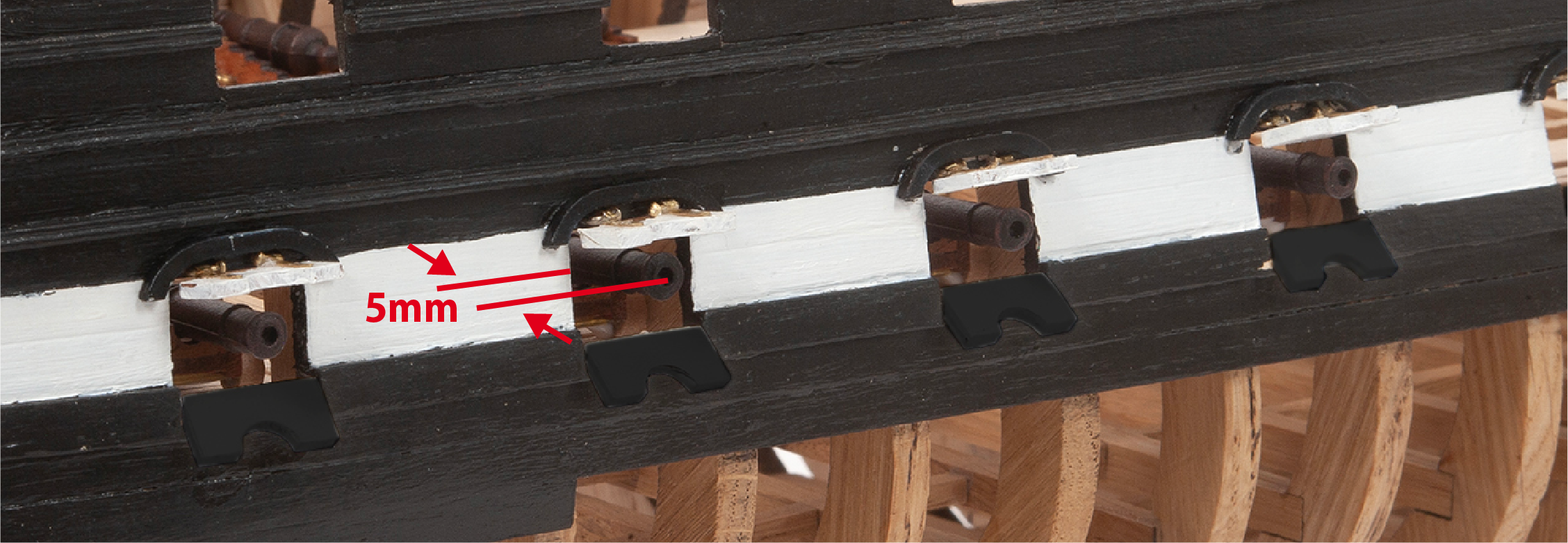
Step 4
Adjust the height and/or inclination of the barrels by filing the wheels slightly. Then apply white glue to the wheels and fit 15 barrels arranged as shown in the picture. Proceed in the same way to fix the 15 barrels on the other side of the hull. It is important that you apply enough glue to secure them to the deck. Once dried, the glue will be transparent and invisible.
Step 1
In this picture you can see the ship with all the guns and gunports of the first battery in place.
Step 2
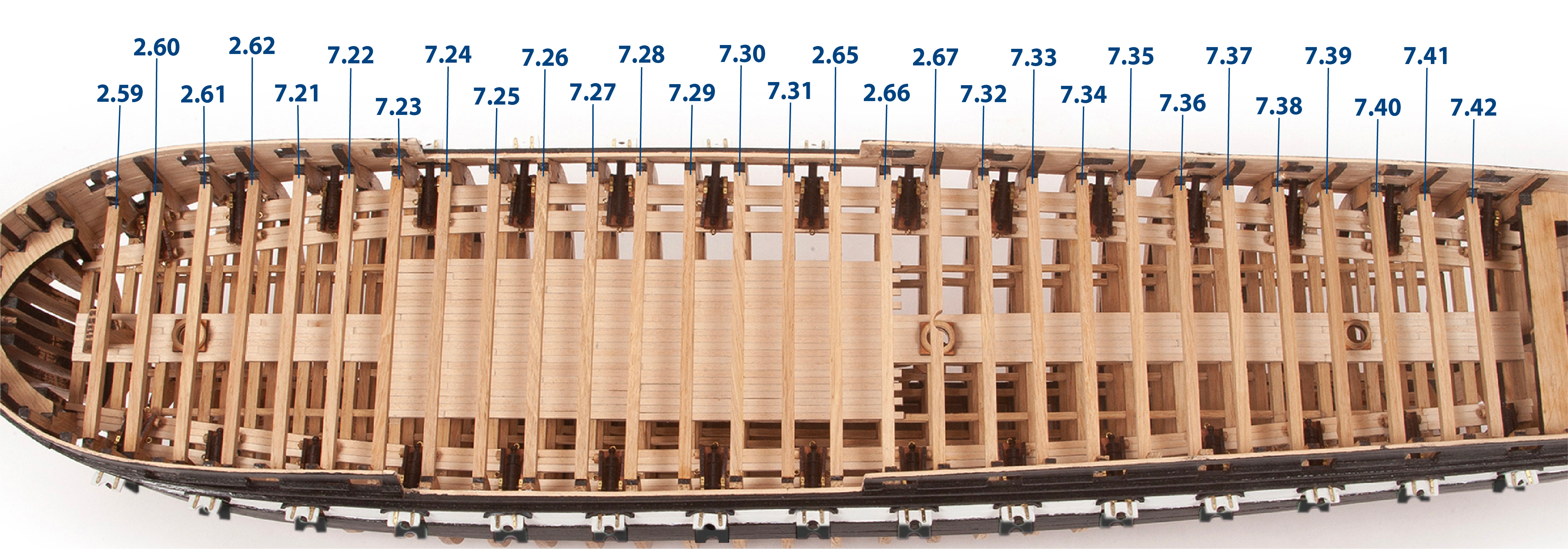
Take beams 2.59 to 2.62, and 2.65 to 2.67 (prepared in pack 2), and glue them to their corresponding frames. Cut to length and glue beams 7.21 to 7.42 to complete the main deck frames.
Step 1
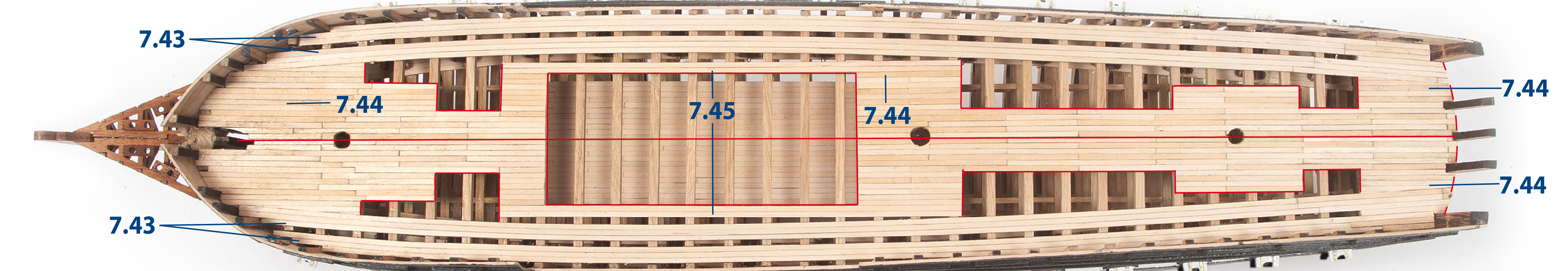
Fit and glue the 7.43 (2 x 3 x 600 mm, supplied with pack 6) strips on both sides of the main deck. Complete them with smaller lengths. Also cut to length and glue pieces 7.44 (appx. 85 mm) and 7.45 (appx. 160 mm).
Step 2
Sand the deck to achieve a uniform finish.
Step 3
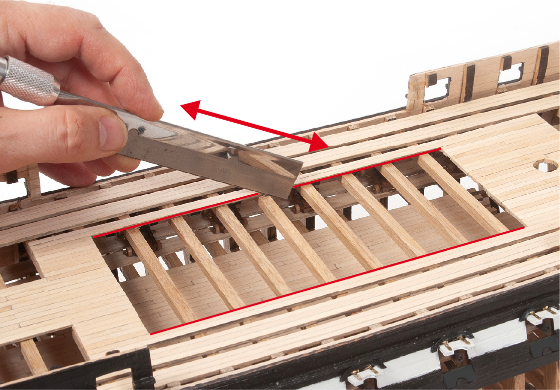
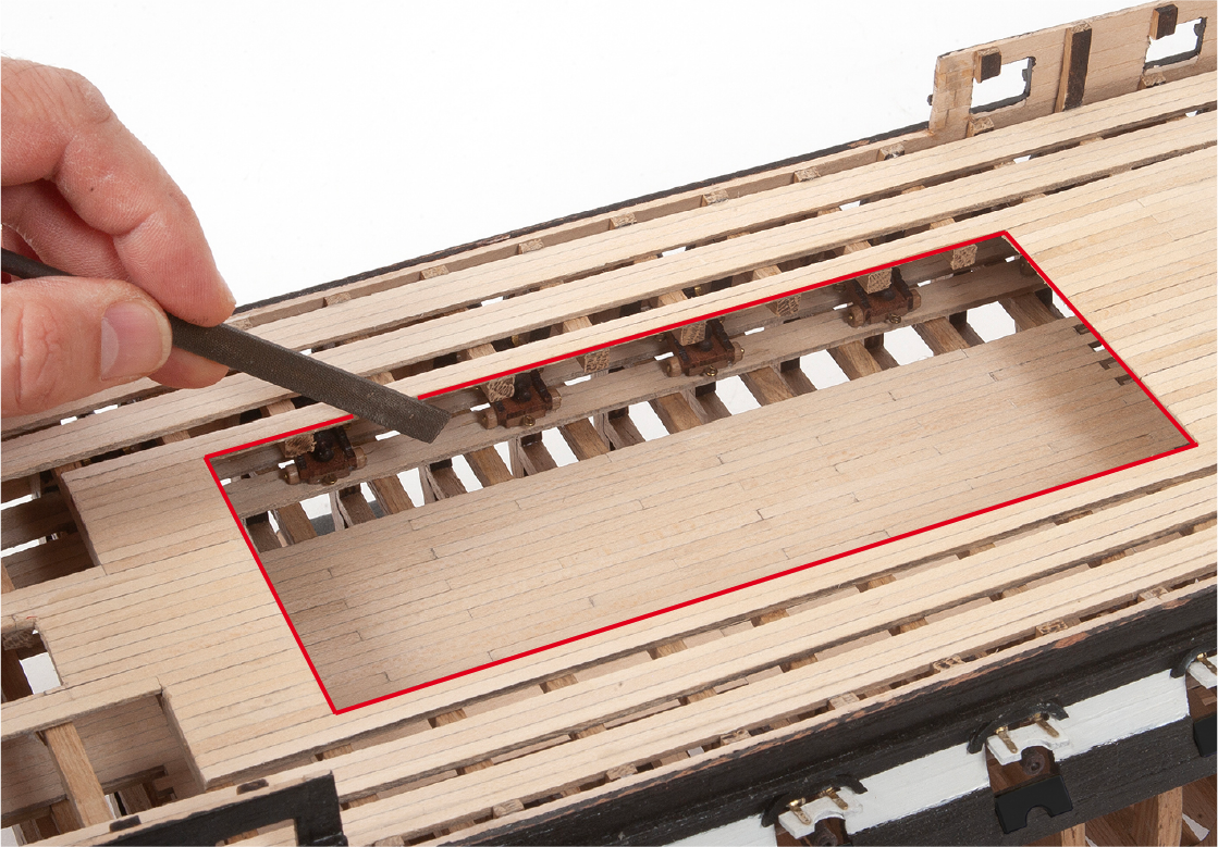
Use a cutting tool to trim the beams in the central opening of the deck.
Step 4
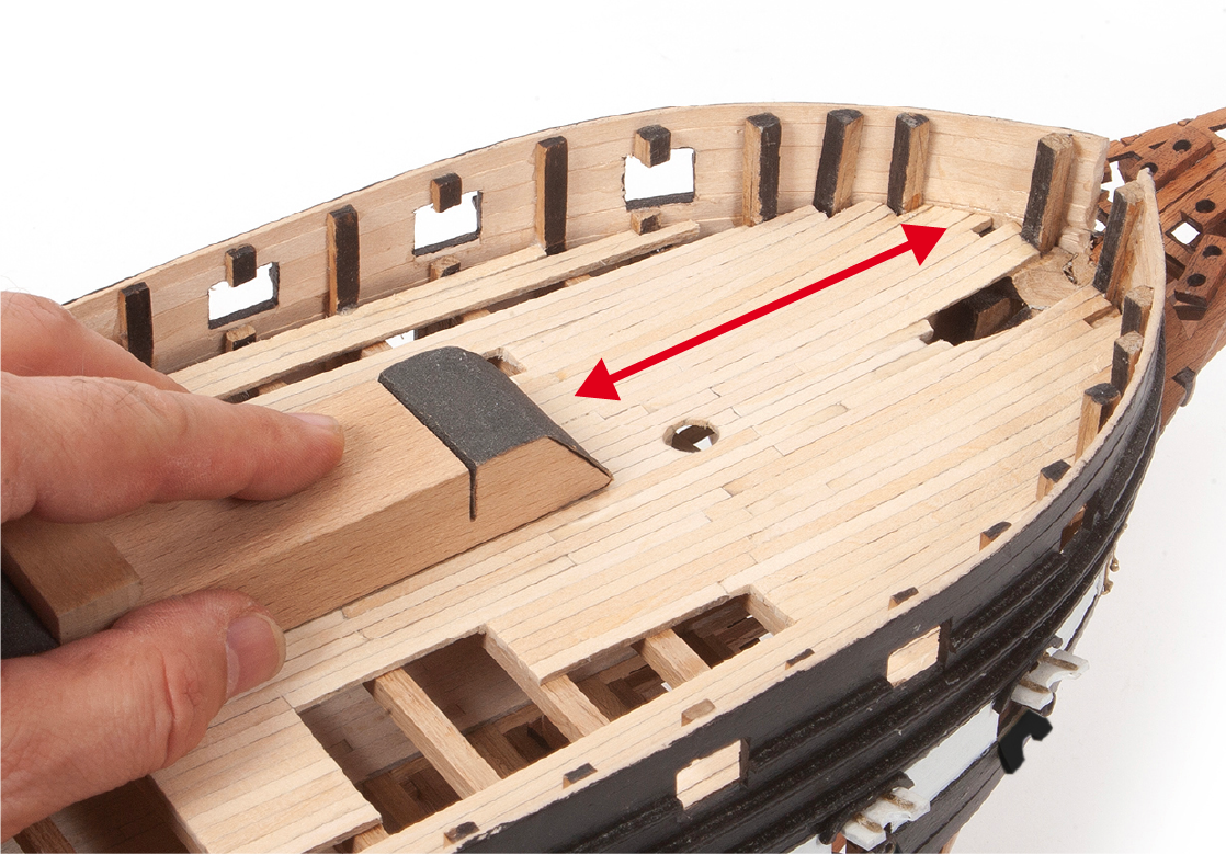
Use a flat file to smooth out the area shown.
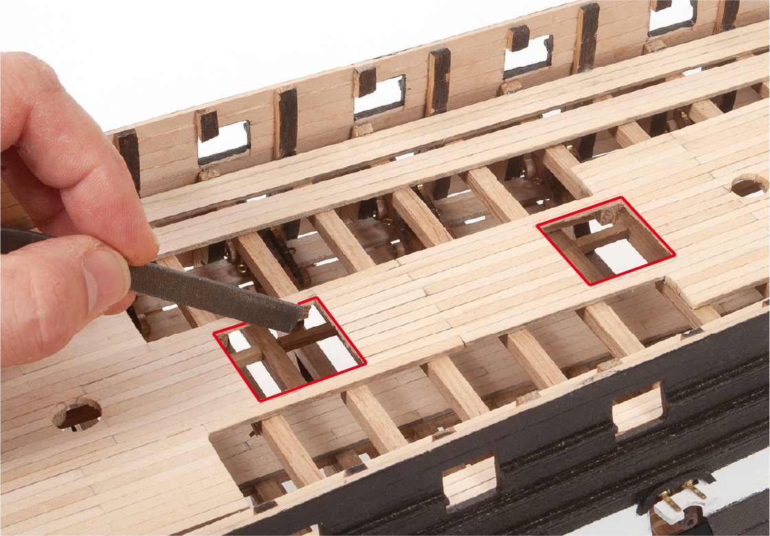
Step 5
Open two more holes in the aft section of the main deck. You may need to trim some beams accordingly.
Refer to the deck plan for guidance.
Step 6
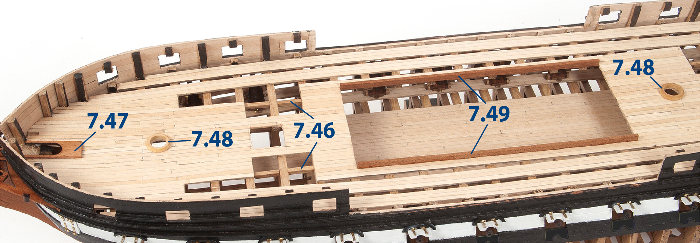
Fit and glue the parts as shown in the picture. Check the fit of the rods for the mast holes. Glue parts 7.49 flush with the underside of the deck lining.
7.46 = 3 x 3 x 17 mm lime wood (pack 4)
7.49 = 2 x 6 x 175 mm mahogany (pack 5)
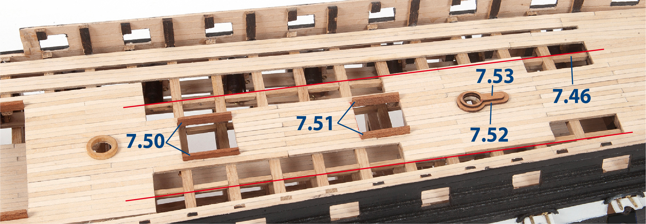
Step 7
Proceed in the same way to fit and glue the parts indicated in the picture.
7.50 = 2 x 6 x 25 mm mahogany (pack 5)
7.51 = 2 x 6 x 19 mm mahogany (pack 5)
Step 8
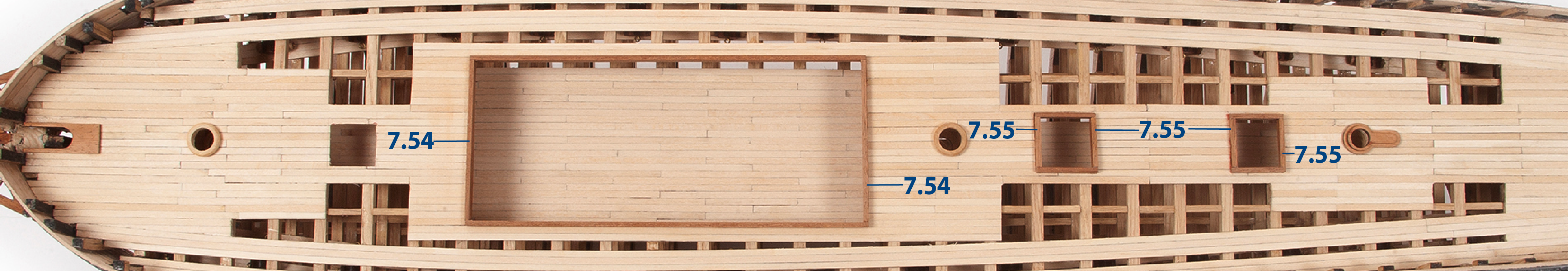
Complete the frames of the openings with the pieces indicated in the picture.
7.54 = 2 x 6 x 71 mm mahogany (pack 5)
7.55 = 2 x 6 x 21 mm mahogany (pack 5)
Step 1
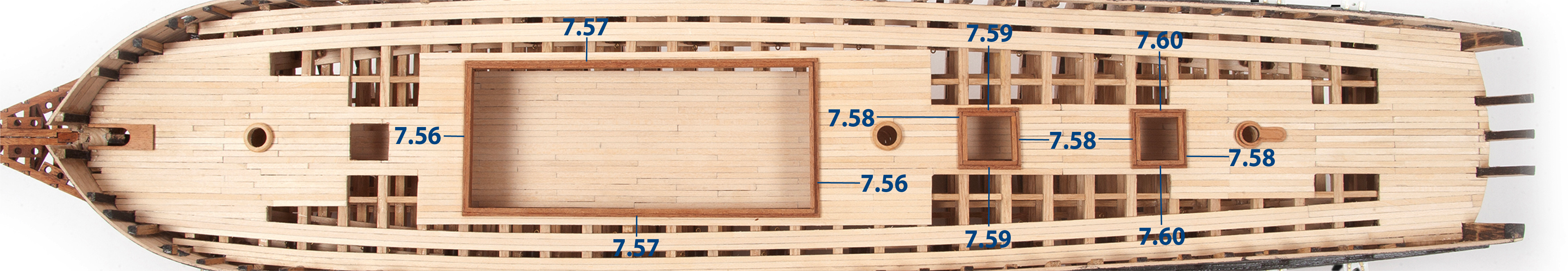
Add the parts indicated in the image (see detail picture in step 2 below).
7.56 = 2 x 2 x 75 mm mahogany (pack 5)
7.57 = 2 x 2 x 179 mm mahogany (pack 5)
7.58 = 2 x 2 x 25 mm mahogany (pack 5)
7.59 = 2 x 2 x 31 mm mahogany (pack 5)
7.60 = 2 x 2 x 27 mm mahogany (pack 5)
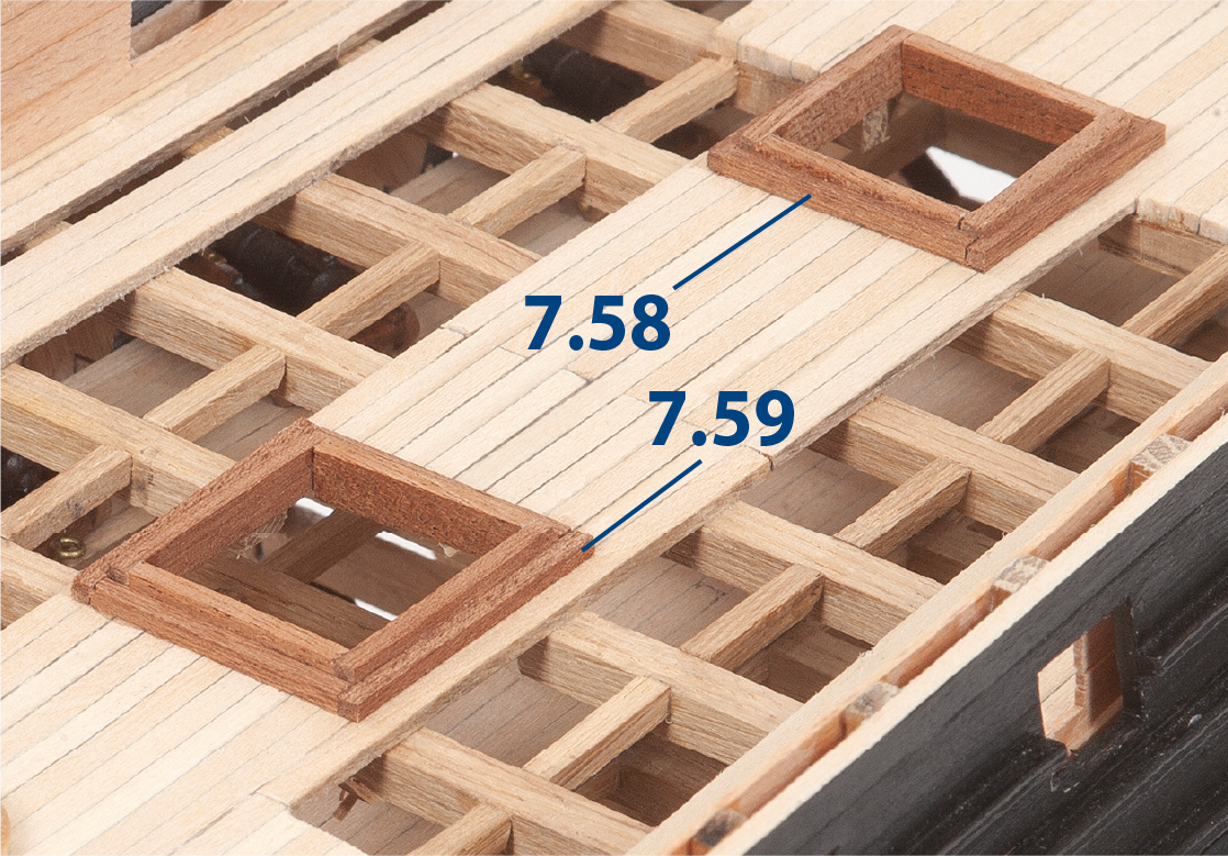
Step 2
In this picture you can see how the inner and outer frames look.
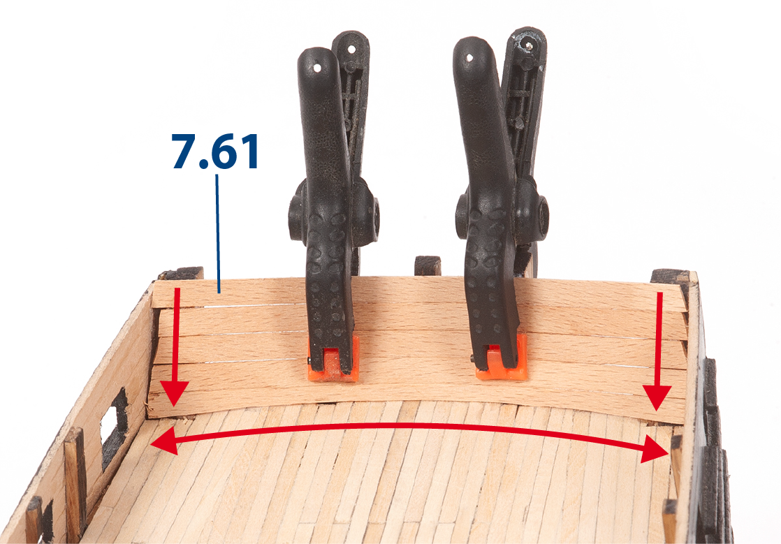
Step 3
Fit and glue the 7.61 (1 x 5 mm lime wood, supplied in pack 5) parts to the inside of the aft frames. Use clamps to hold the parts in place until the adhesive dries.
Step 4
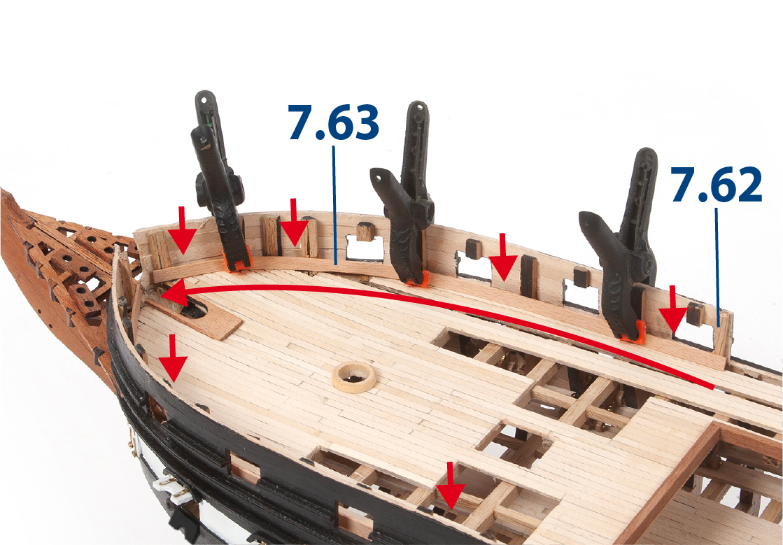
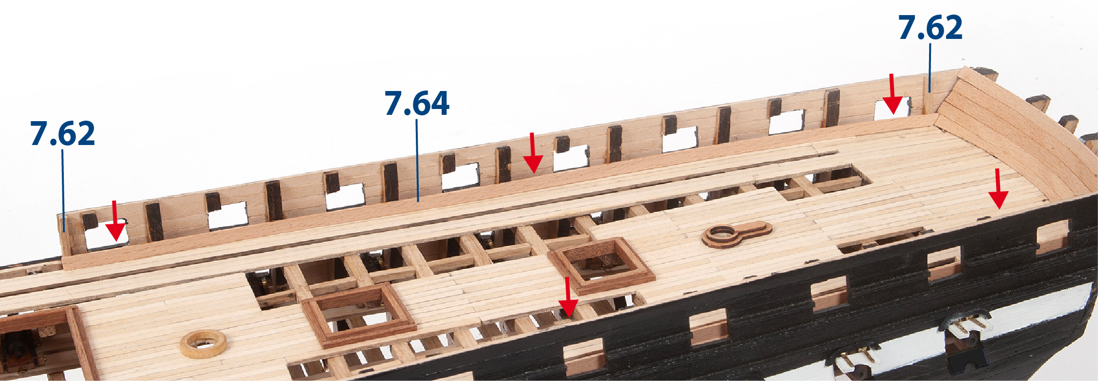
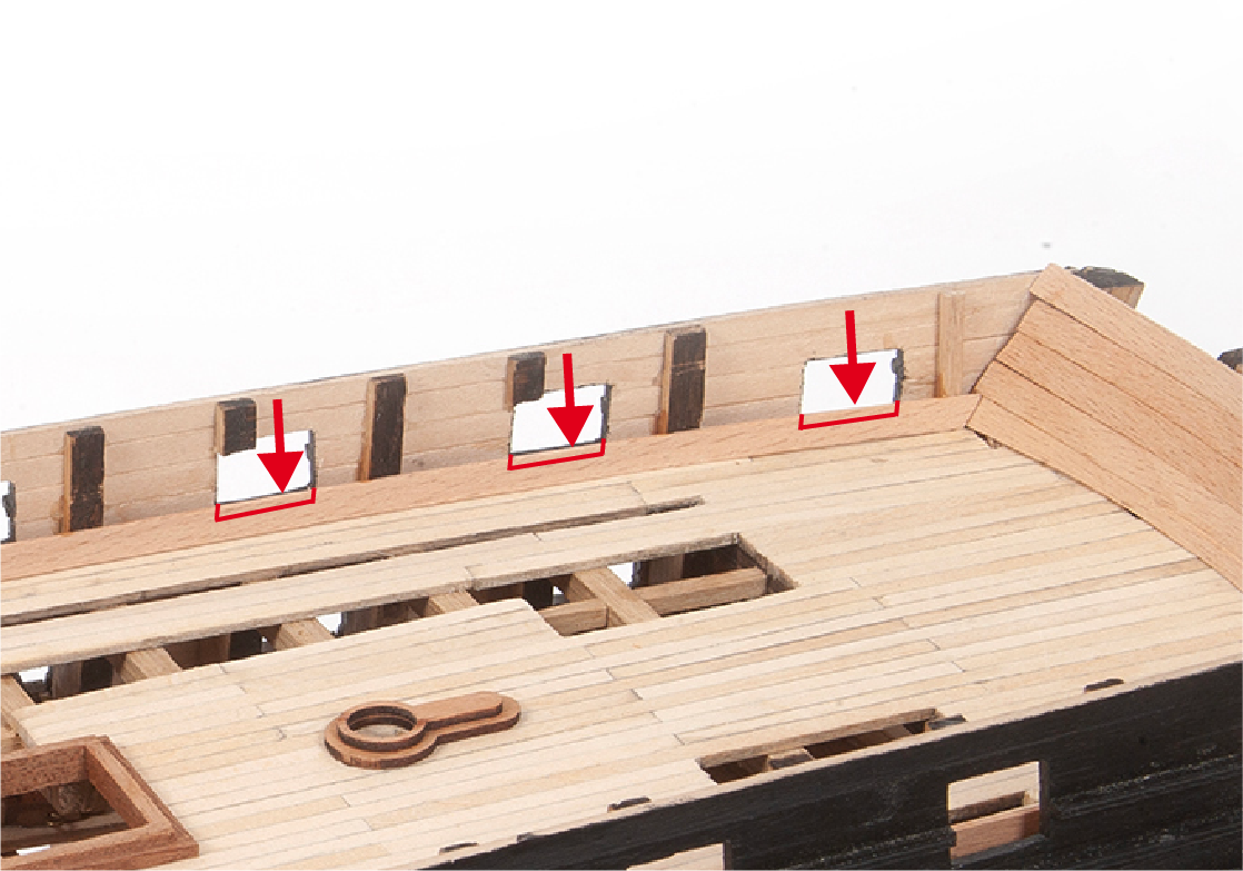
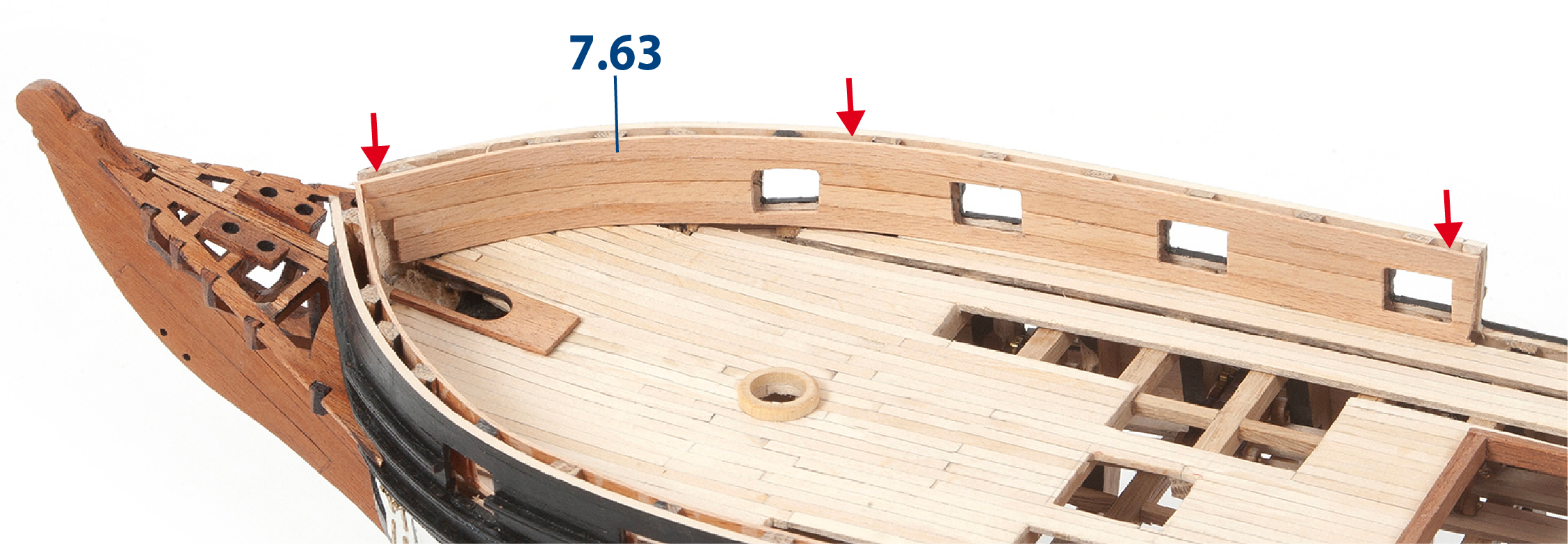
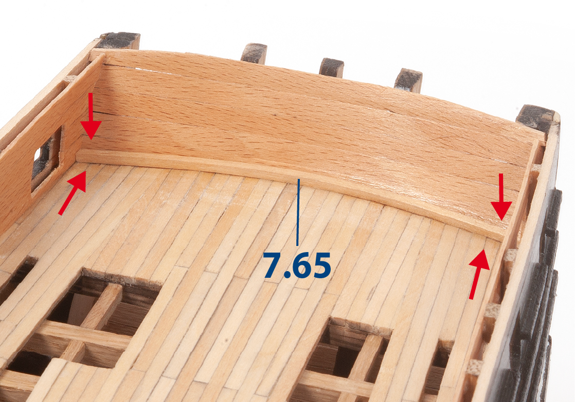
Also fit and glue parts 7.63 (1 x 5 x 240 mm lime wood) to the inside of the bow bulwark. Glue and fit parts 7.62 (3 x 3 x 22 mm lime wood, supplied in pack 4) as required to support parts 7.63.
Step 5
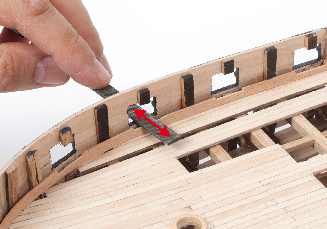
Use a cutter to remove the lining covering the gunports as you proceed with the inner lining of the bulwarks.
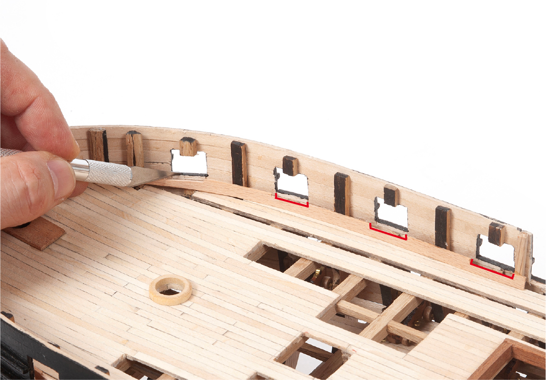
Step 6
File the areas where the lining was cut with a flat file.
Step 7
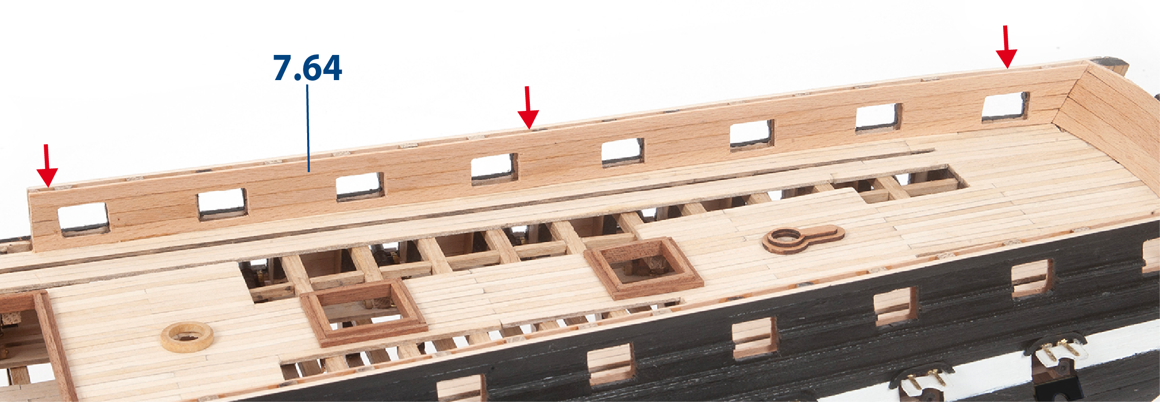
Proceed in the same way to fit parts in the aft bulwark, as shown in the picture.
Step 8
Remove the inner lining covering the gunports.
Step 9
Complete the inner lining of the bow bulwark.
Step 10
Also complete the inner lining of the aft bulwark.
Step 1
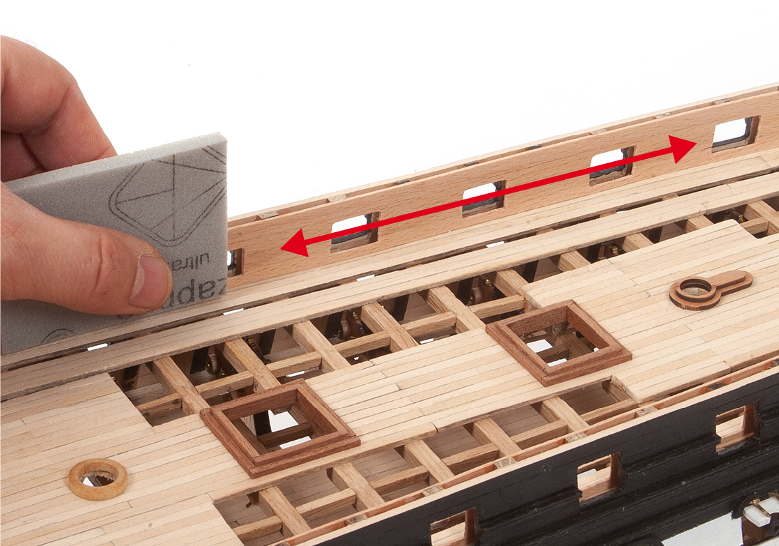
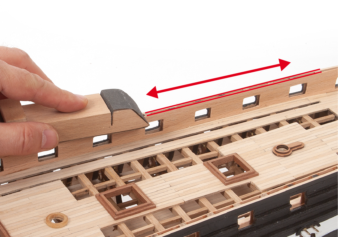
Use a fine-grit sanding sponge to smooth the inner lining of the bulwarks.
Step 2
Sand the top of the inner and outer planking along the entire length of the hull.
Step 3
Adjust and fit a batten 7.65 (2 x 2 x 105 mm lime wood, supplied in pack 6).
Step 4
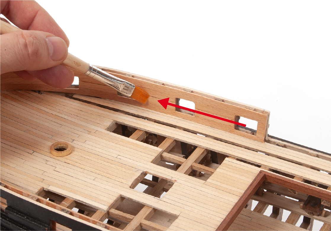
Apply varnish to the entire inner lining.
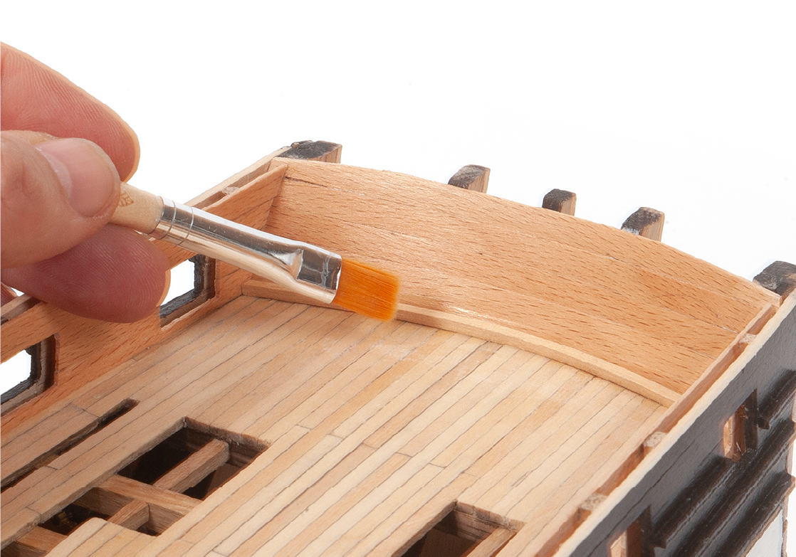
Step 5
Proceed in the same way to varnish the bow area.
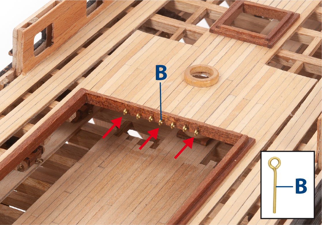
Step 6
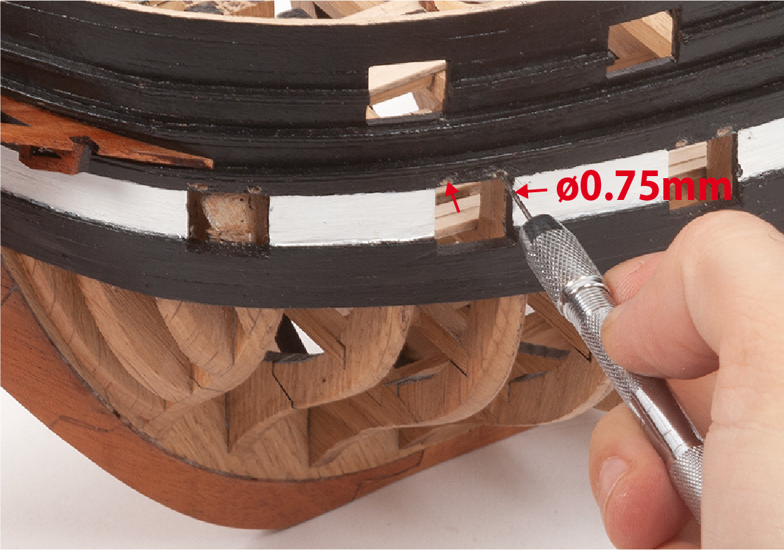
Drill ø 0.75 mm holes then insert and fit the eyebolts B (supplied in pack 5) shown in the picture. Use the deck plan as a reference.
Step 7
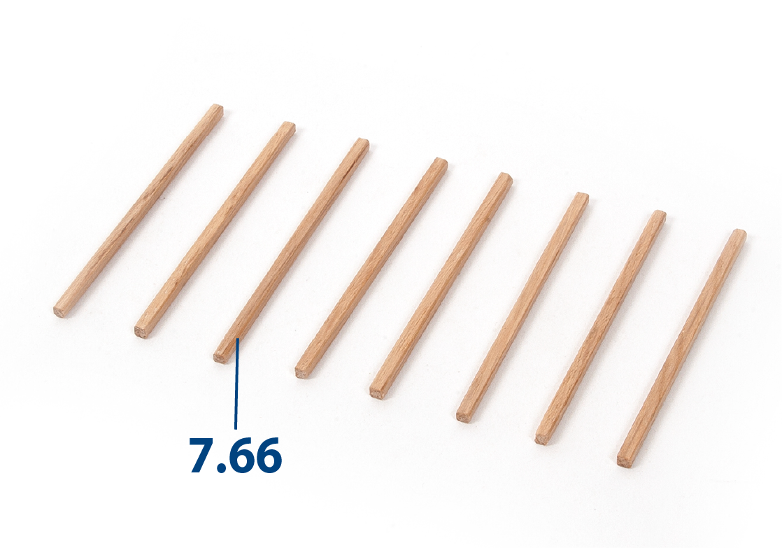
Make parts 7.66 (3 x 3 x 74 mm lime wood, supplied in pack 4) and varnish them.
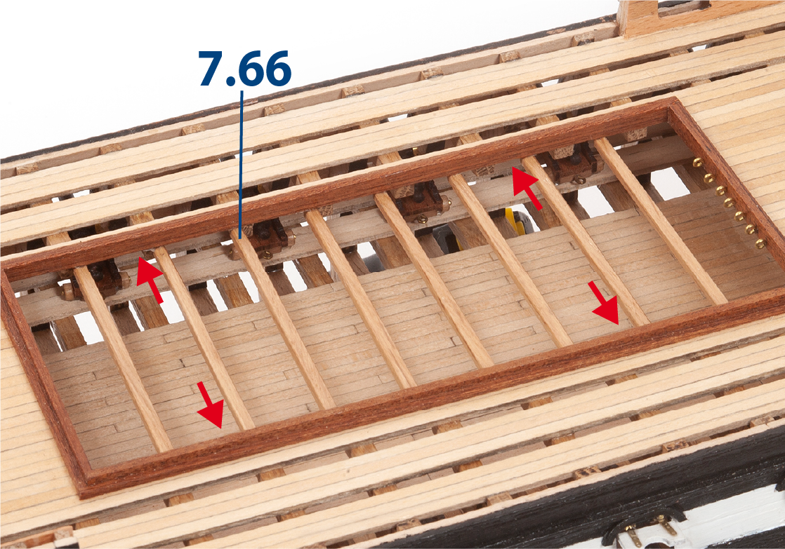
Step 8
Fit and glue parts 7.66 as shown. Refer to the deck plan for the layout.
Step 9
Use a drill and then a file to open the holes for inserting the bow davits.
Step 10
Fit and glue the adjusted bow davits as shown in the picture.
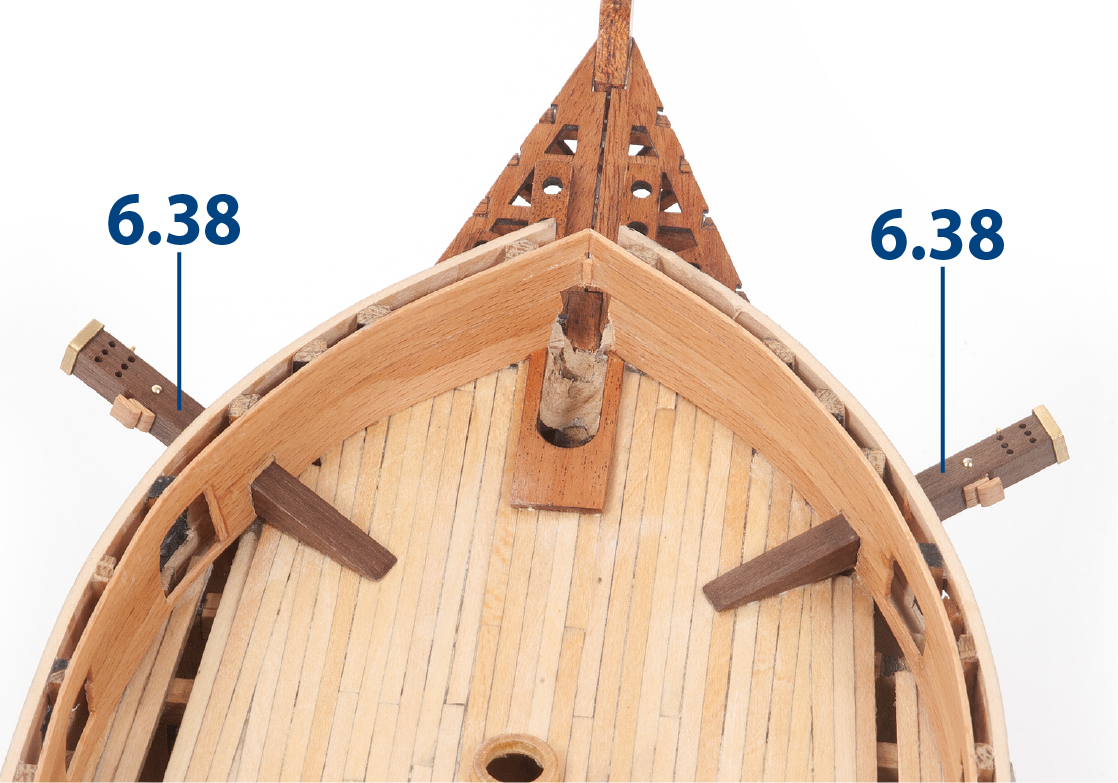
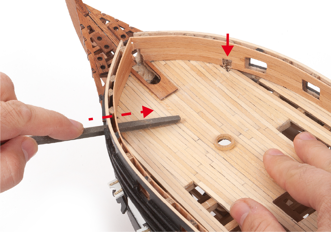
Step 11
The picture shows the fit of the davits in place. Use a tool to cut off the bottom rail in order to be able to insert parts 7.67.
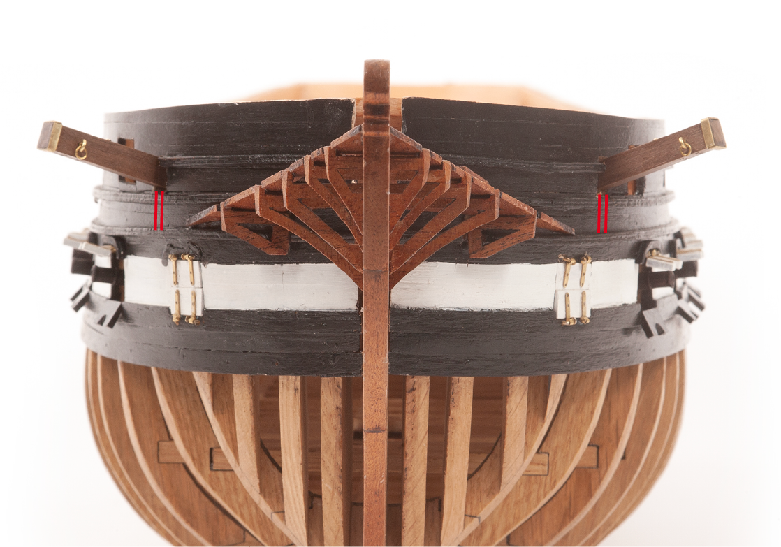
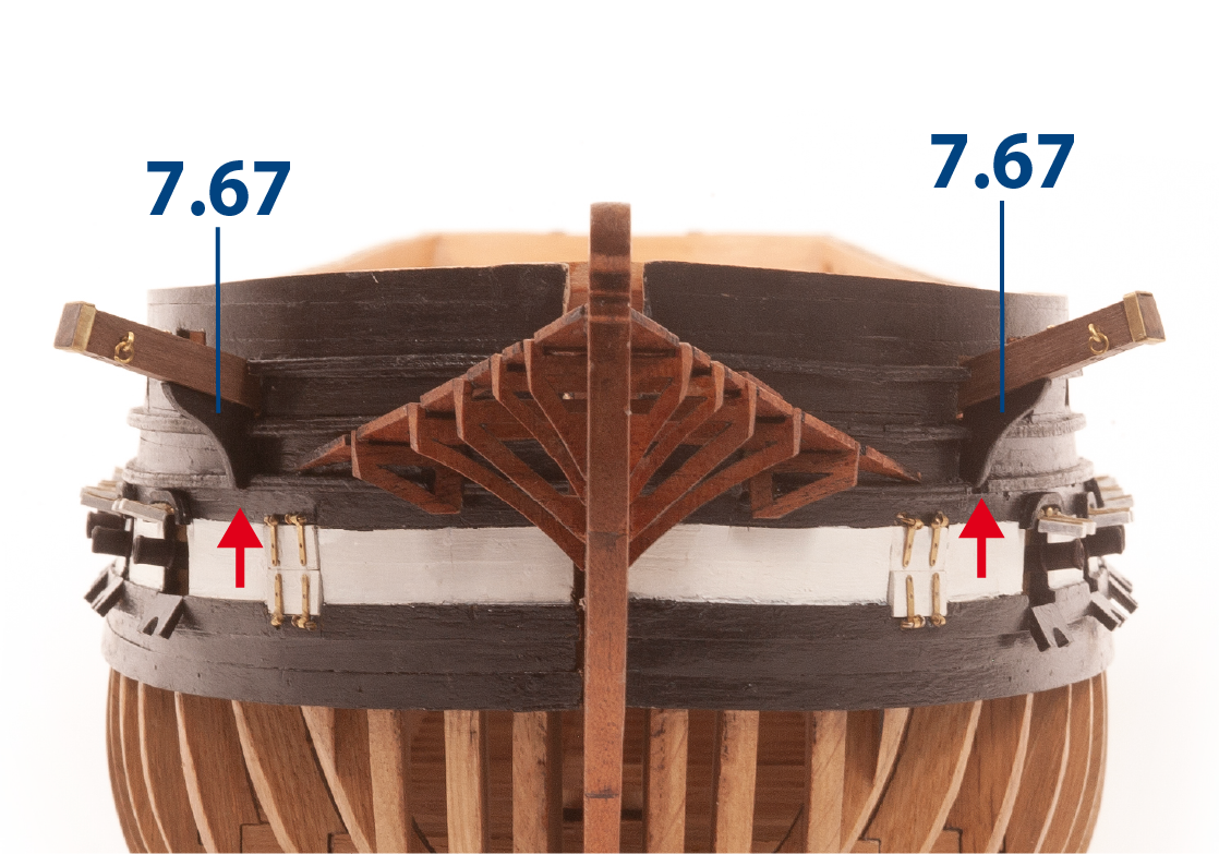
Step 12
Fit and secure parts 7.67. The parts must be adjusted to fit properly. Paint the parts black.
Step 13
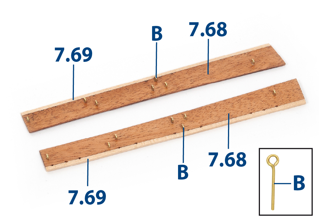
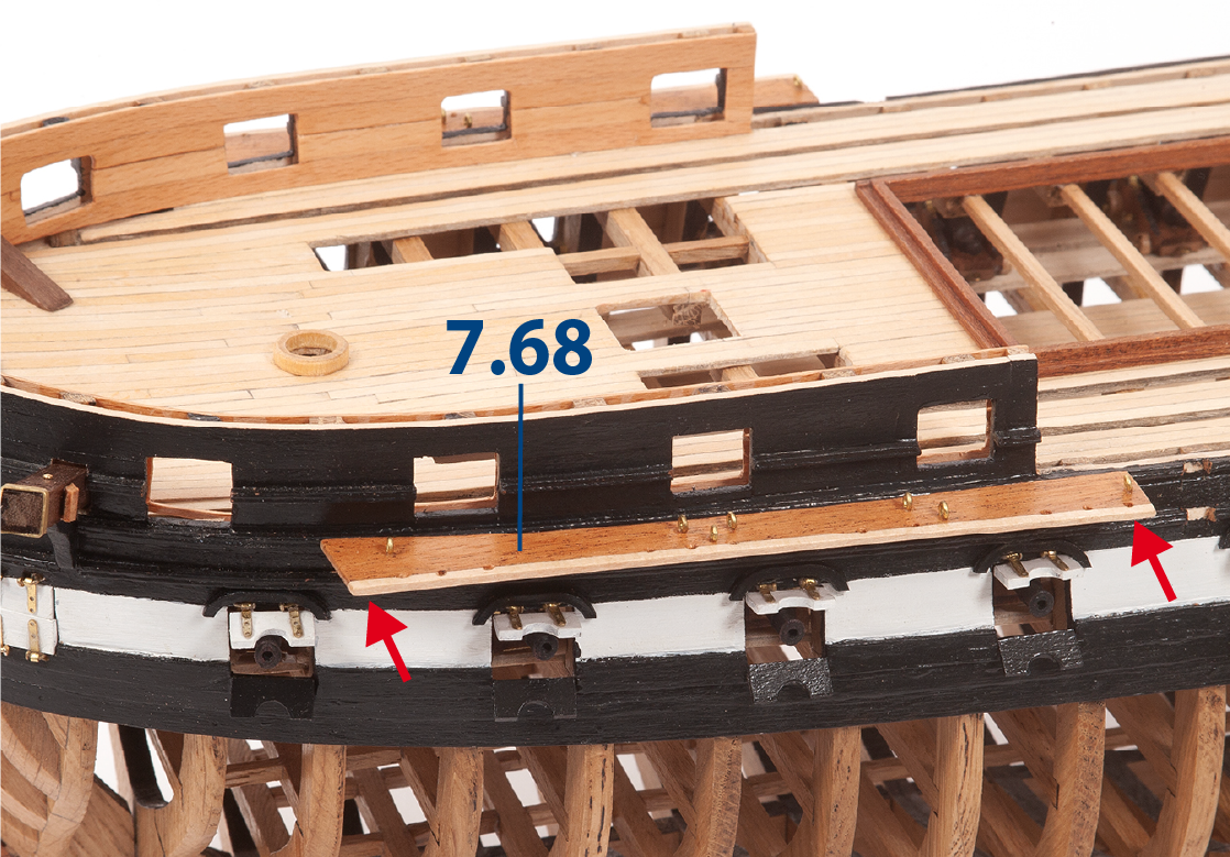
Fit and glue parts 7.69 (2 x 2 mm lime wood, supplied in pack 6) with parts 7.68. Then varnish the parts and insert and fix the eyebolts B as shown in the deck plan. Cut off the part of the eyebolts protruding beneath the parts. These are the fore chain-wales.
Refer to Step 16 and the deck plan for guidance.
Step 14
Proceed in the same way to make and glue parts 7.70 and 7.71 (2 x 2 x 142 mm lime wood) with the eyebolts B. These are the main chain-wales.
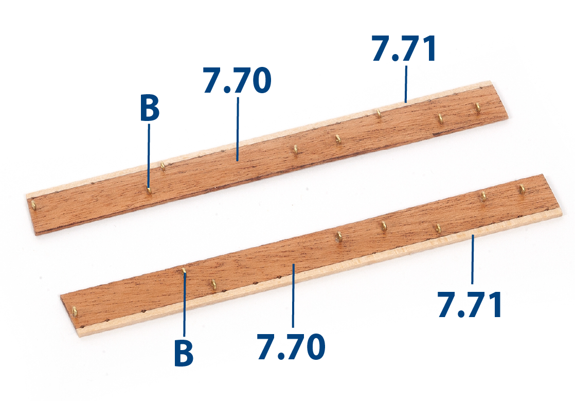
Step 15
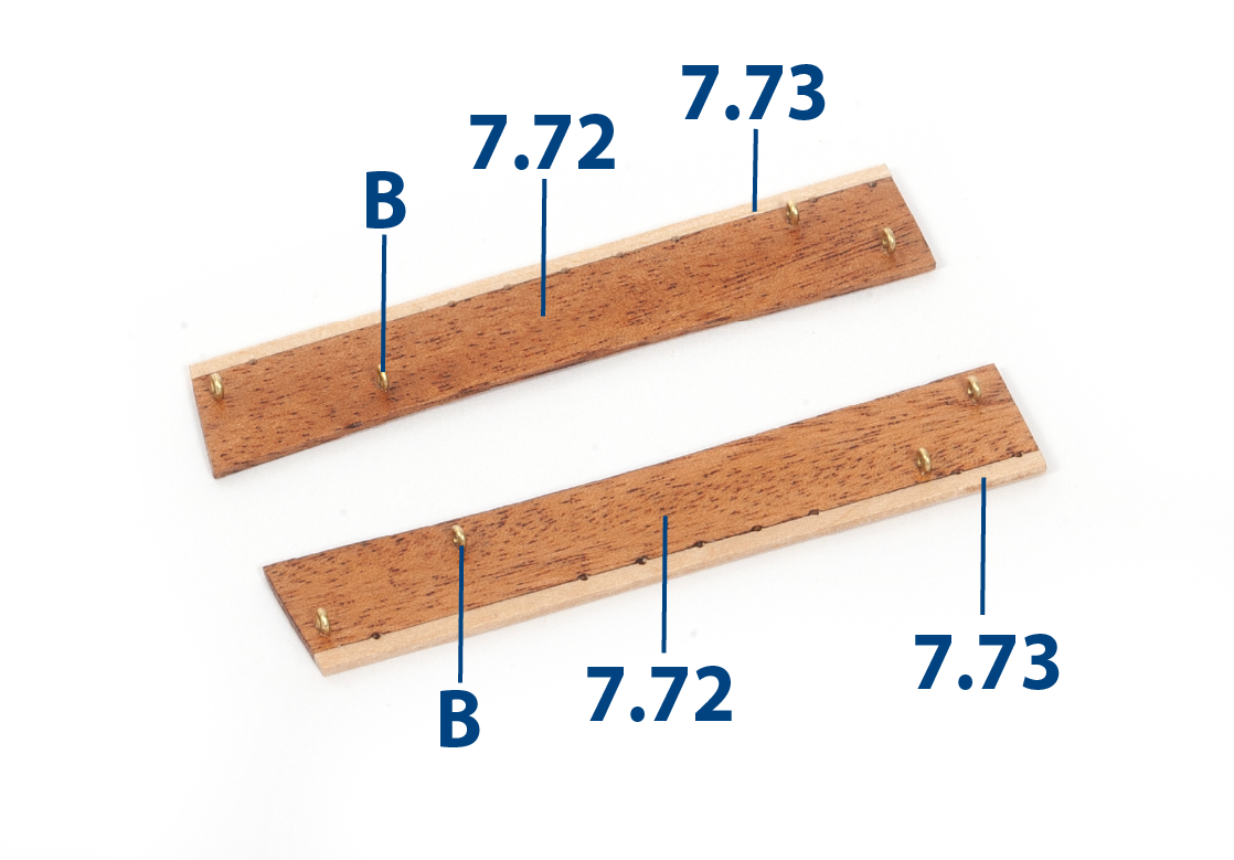
Proceed in the same way to make and glue parts 7.72 and 7.73 (2 x 2 x 83 mm lime wood) and eyebolts B. These are the mizzen chain-wales.
Step 16
Fit and glue parts 7.68 to the sides of the hull. Refer to the plans.
Step 1
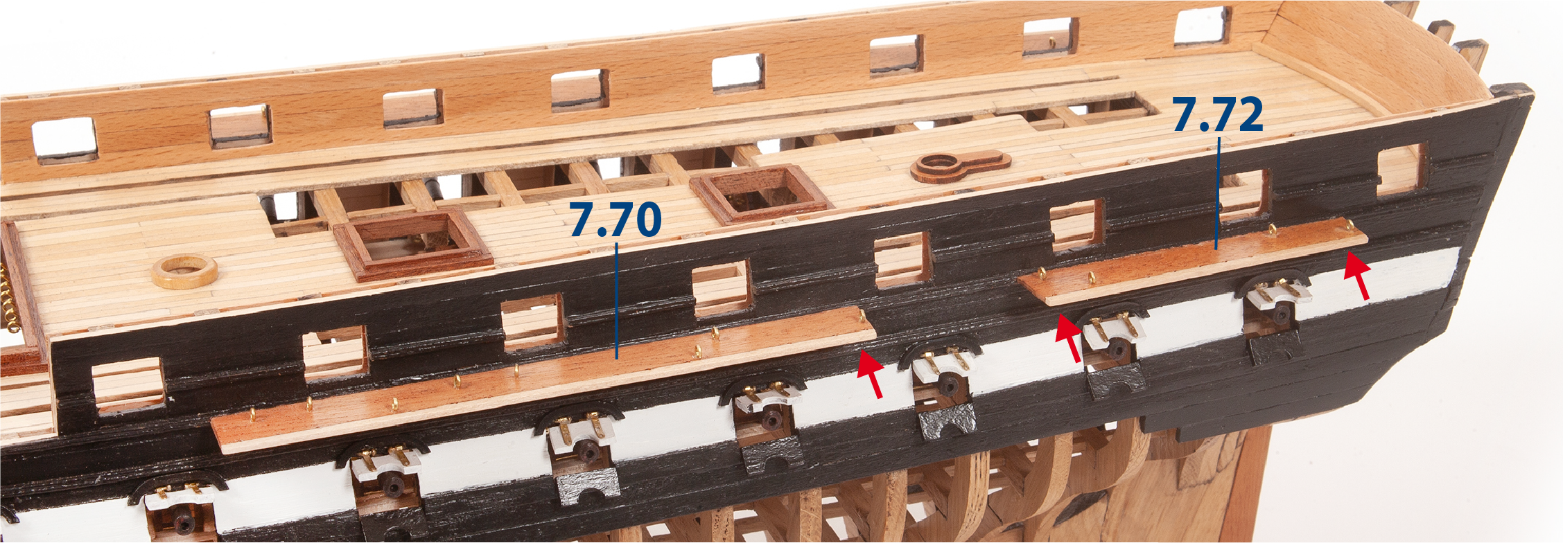
Fit and glue parts 7.70 and 7.72 to the sides of the hull. Refer to the plans.
Step 2
Use a moulding scriber tool to groove the indicated batten (2 x 2 mm mahogany, supplied with pack 5).
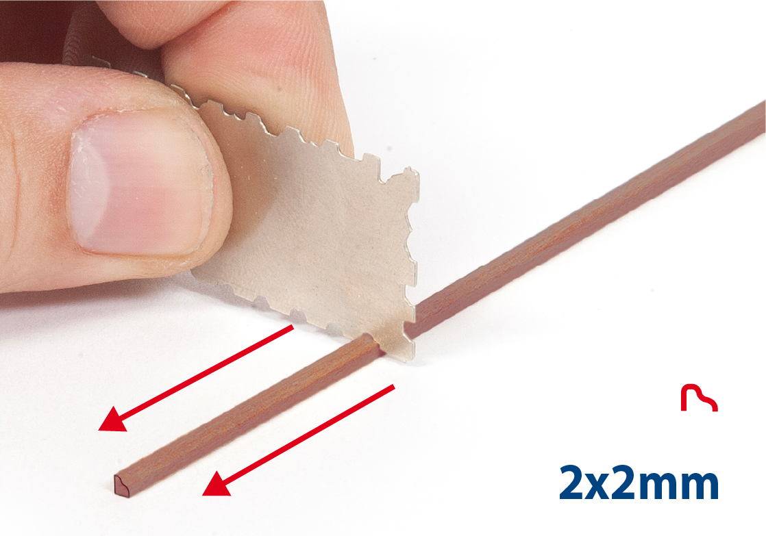
Step 3
Cut parts 7.74 to length (8 mm) and varnish them.
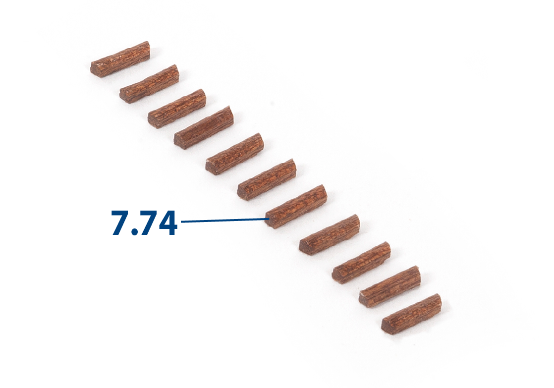
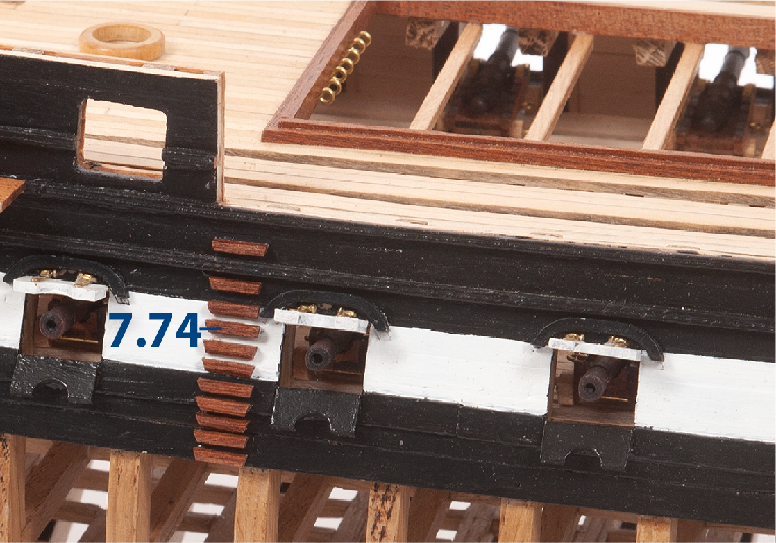
Step 4
Refer to the elevation drawing for positioning parts 7.74 on the side of the hull.
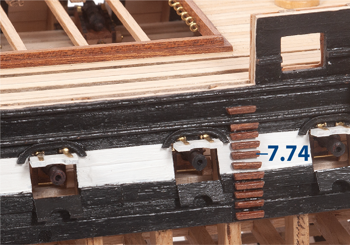
Step 5
Proceed in the same way to glue the boarding steps on the other side of the hull.
Step 6
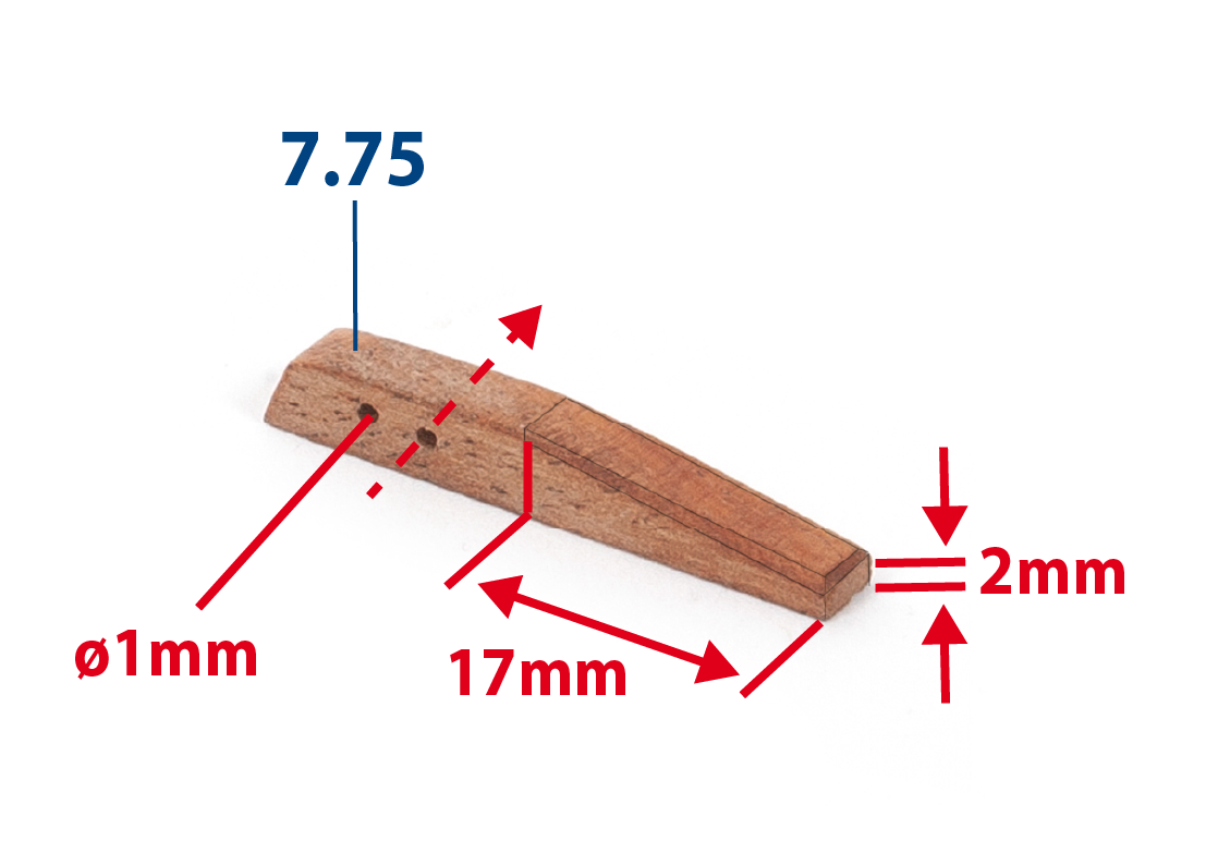
Make the two pieces 7.75 from a 4 x 4 mm mahogany strip (supplied in pack 5) using the measurements shown. Then varnish the parts.
Step 7
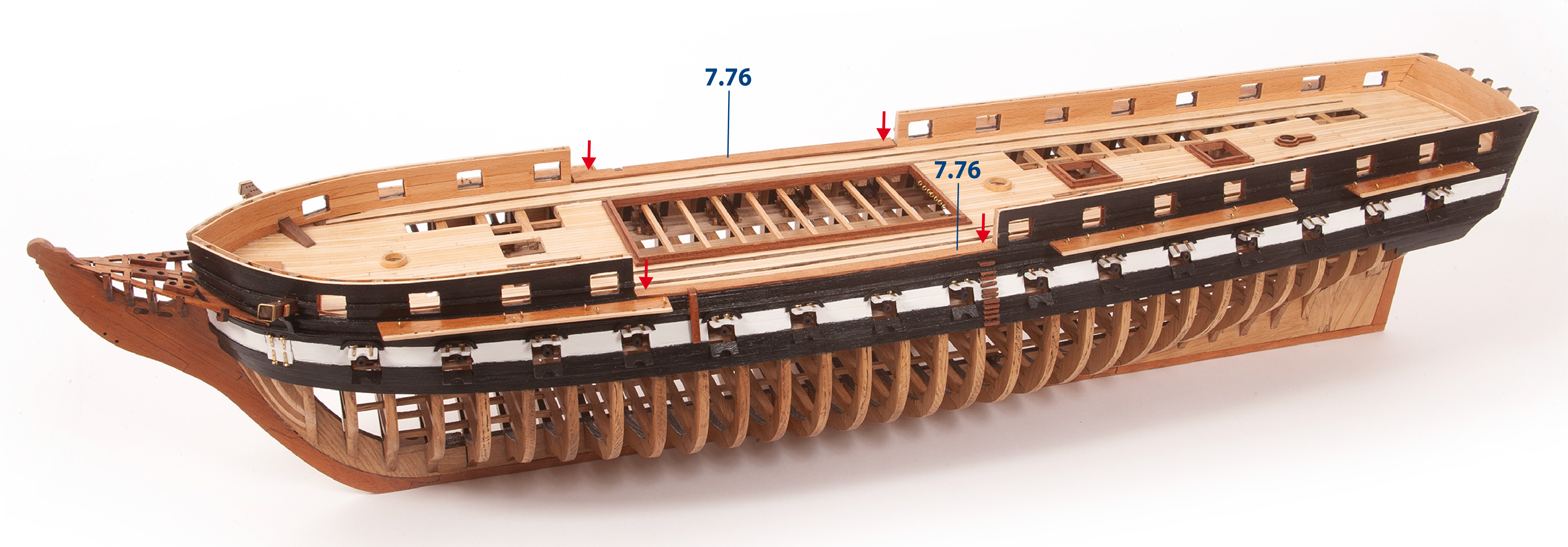
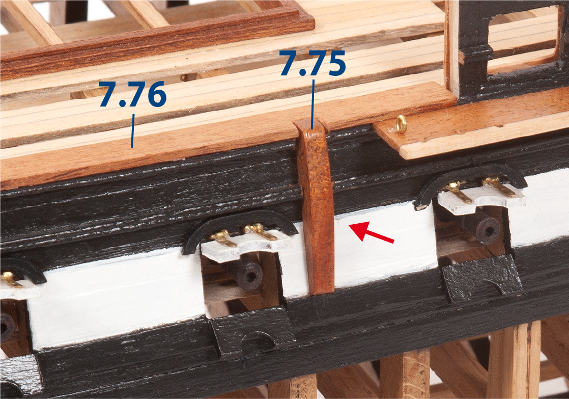
Fit and glue parts 7.76 to both sides of the hull. Cut a recess in the hull to fit parts 7.75.
Step 8
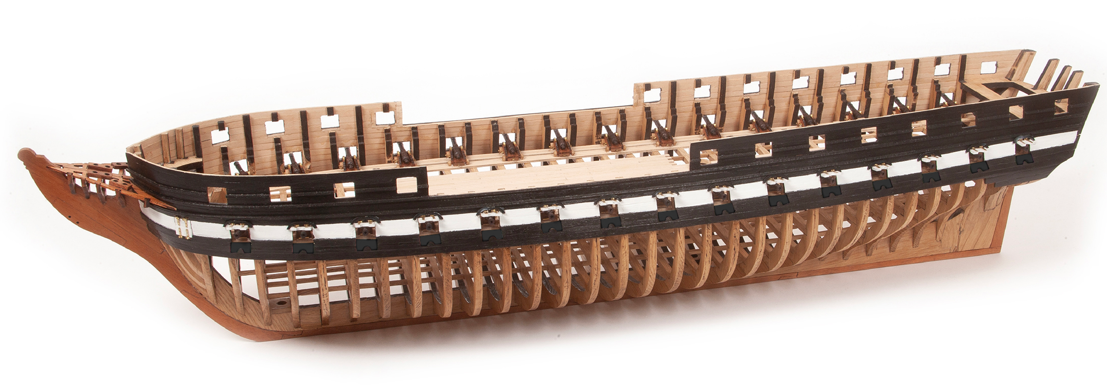
Note in the picture the progress of the ship after the completion of this pack.