Pack 8
BUILD INSTRUCTIONS
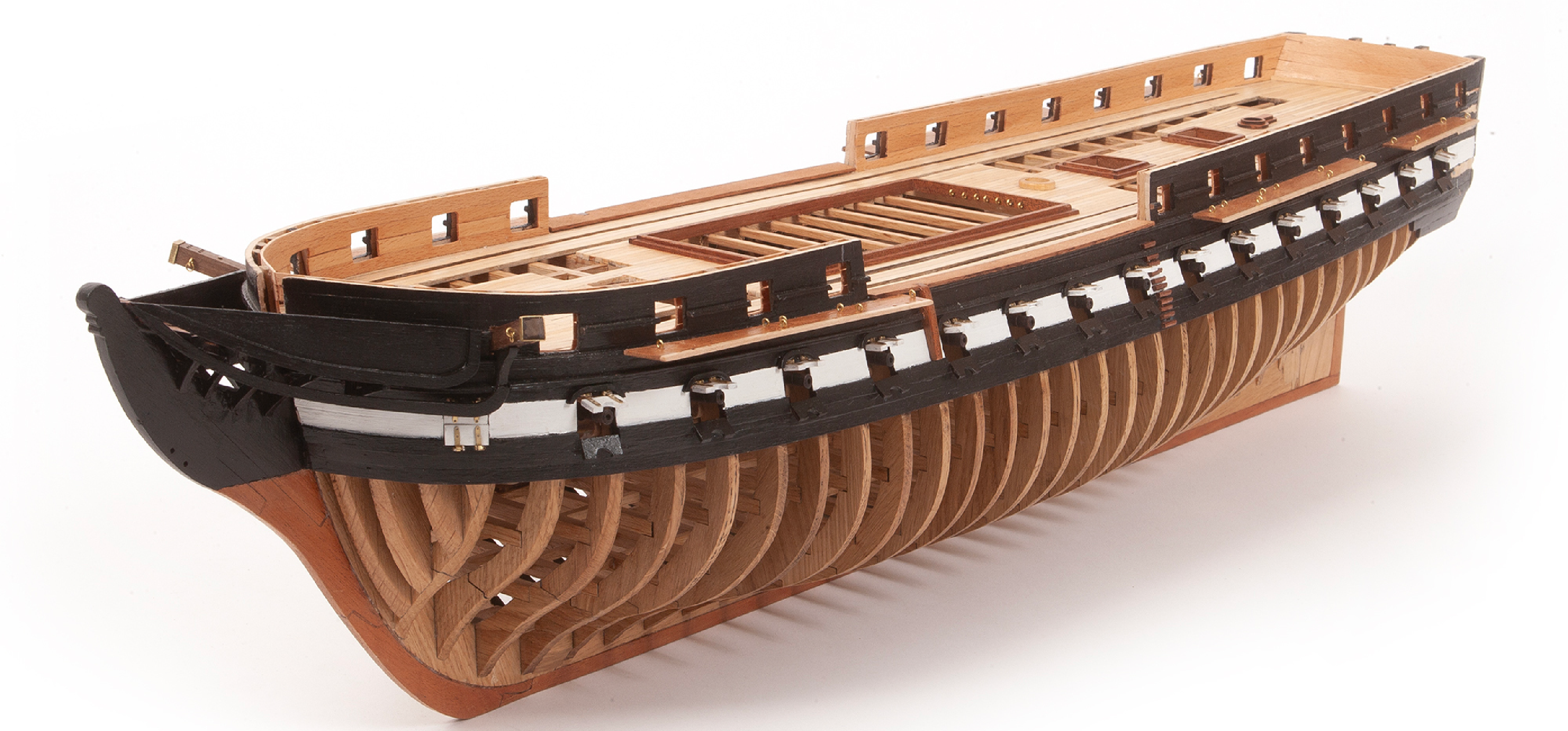
Instructions for building your USS Constitution model ship
Your model of the USS Constitution is divided into 12 packs.
You will need to follow the step-by-step assembly photos, the plans and the explanatory texts below.
Please save the leftover materials from each pack for use when instructed to do so at a later stage of the assembly instructions.
The IP sheets displayed below are drawings of laser-cut parts and photo-etched brass parts and will serve as a guide for identification of some parts.
Use the PARTS REFERENCE table to help locate the parts.
The PL-00 templates (printed at 1/1 scale) included in each pack will serve as a guide for building the model.
Please check the list below to ensure you have all the tools required for building your wooden ship.
When removing a part, cut the ribs that join the part to the wooden plate with a cutter.
Remove the parts carefully so as not to break them.
Keep and store the parts in their frames. Only remove the parts you are working on in each step.
Extra support can be found on our forum or from the Expert Directory page of our website.
PARTS LIST
| Material | Quantity | |
| Boards 2001-20, 2001-21, 2001-22 | Wood | 3 |
| Wooden Strips | ||
| 2 x 3 x 600 mm | Lime wood | 5 |
| 1 x 3 x 600 mm | Lime wood | 35 |
| 2 x 2 x 600 mm | Mahogany | 10 |
| 3 x 3 x 400 mm | Lime wood | 4 |
| 2 x 2 x 600 mm | Lime wood | 4 |
| 5 x 5 x 400 mm | Oak | 2 |
| Other Parts | ||
| Steering wheel | 2 | |
| Steering pedestal | 2 | |
| Capstan | 1 | |
| Wire (ø1.5 x 100 mm) | Brass | 5 |
| Chimney | 1 | |
| Binnacle | 2 | |
| Port gallery base | 1 | |
| Starboard gallery base | 1 | |
| Port gallery crown | 1 | |
| Starboard gallery crown | 1 | |
| Upper transom ornament | 1 | |
| Port upper transom ornament | 1 | |
| Starboard upper transom ornament | 1 | |
| Port stern ornament | 1 | |
| Starboard stern ornament | 1 | |
| Port lower transom ornament | 1 | |
| Starboard lower transom ornament | 1 | |
| Winch drum (5 x 5 mm) | 2 | |
| Wire (ø1 x 400 mm) | Brass | 8 |
| Rod (ø3 x 400 mm) | Mahogany | 1 |
| Walnut stain (100 ml) | 1 | |
| Judea Bitumen (30 ml) | 1 |
Tools you will need: cutting mat, pencil, cutting knife, fine-grit sandpaper or sponge sandpaper, file, white wood glue, super glue (cyanoacrylate glue), masking tape, set square, hacksaw, sanding block, 30 cm steel ruler, clamps, drill, moulding scriber tool
PACK 08 IDENTIFICATION SHEETS
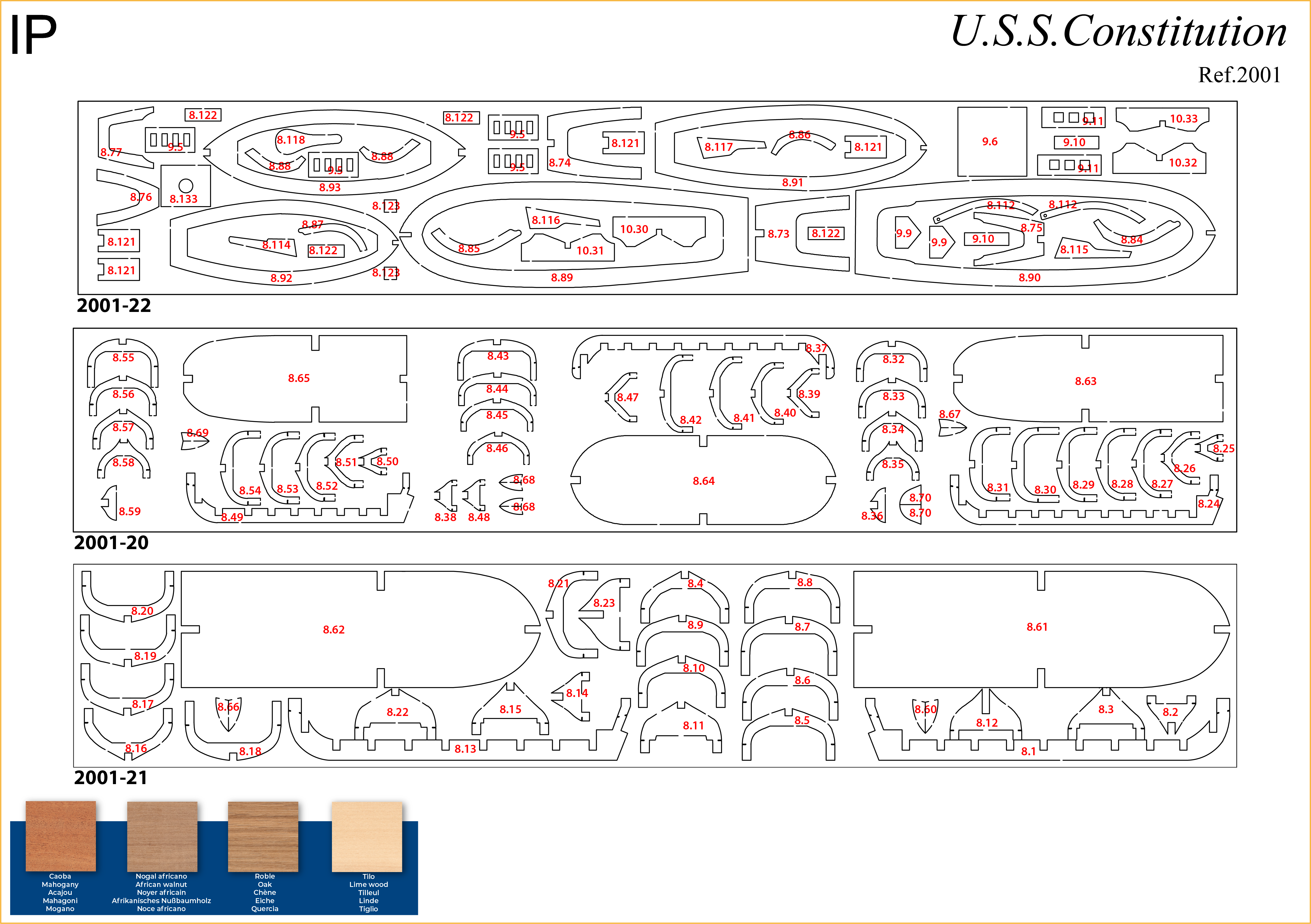
PARTS REFERENCE
PART NO. | IP-SHEET LOCATION | PART NO. | IP-SHEET LOCATION | PART NO. | IP-SHEET LOCATION |
| 8.1 | 2001-21 | 8.60 | 2001-21 | 8.121 – 8.123 | 2001-22 |
| 8.2 – 8.12 | 2001-21 | 8.61 – 8.62 | 2001-21 | 8.132 | 2001-23 |
| 8.13 | 2001-21 | 8.63 – 8.65 | 2001-20 | 8.133 | 2001-22 |
| 8.14 – 8.23 | 2001-21 | 8.66 | 2001-21 | 8.136 | 2001-23 |
| 8.24 | 2001-20 | 8.67 – 8.70 | 2001-20 | 8.137 | 2001-30 |
| 8.25 – 8.36 | 2001-20 | 8.73 – 8.77 | 2001-22 | 8.138 | 2001-23 |
| 8.37 | 2001-20 | 8.84 – 8.88 | 2001-22 | 8.147 | 2001-23 |
| 8.38 – 8.48 | 2001-20 | 8.89 – 8.93 | 2001-22 | 8.153 | 2001-11 |
| 8.49 | 2001-20 | 8.112 | 2001-22 | 8.154 | 2001-11 |
| 8.50 – 8.59 | 2001-20 | 8.114 – 8.118 | 2001-22 | 8.155 | 2001-11 |
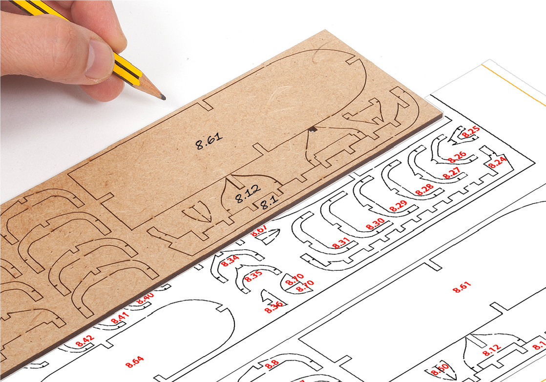
Step 1
Building the U.S.S. Constitution's small boats
Use a pencil to transfer the numbers from the IP sheets to the wooden boards.
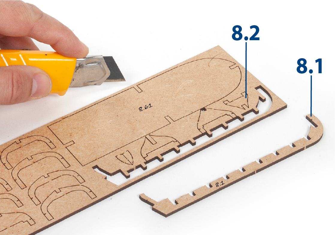
Step 2
Cut the ribs that join the pieces to the boards, so that they can be removed without damaging them.
Step 3
Place the parts on a flat surface and sand them with a fine-grit sponge.
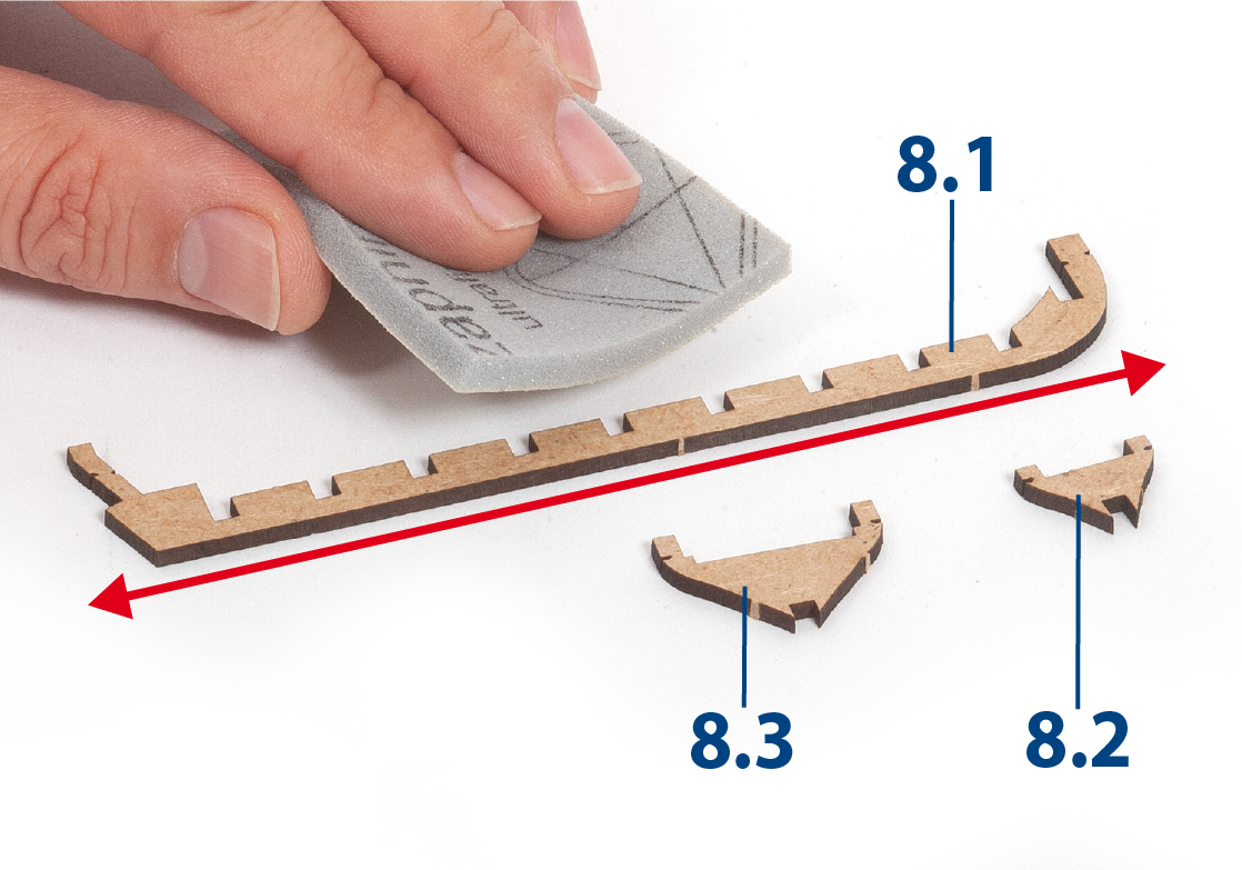
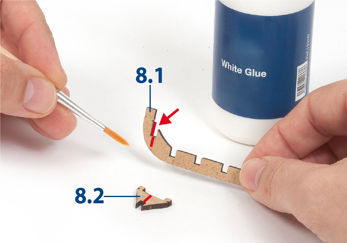
Step 4
Glue part 8.2 to part 8.1.
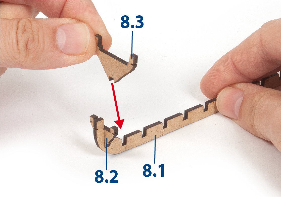
Step 5
Glue part 8.3 to part 8.1.
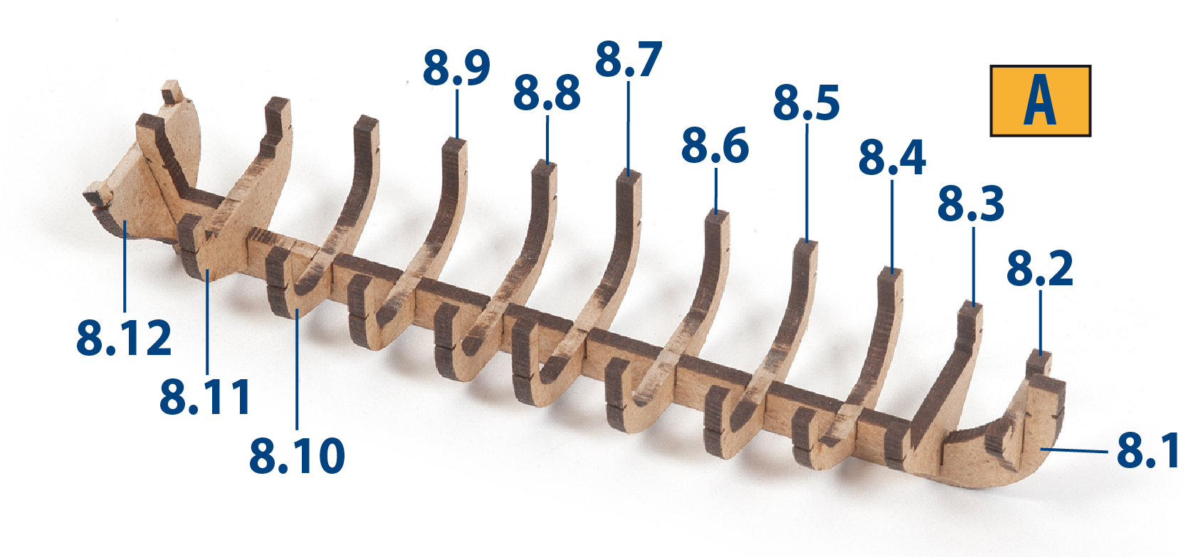
Step 6
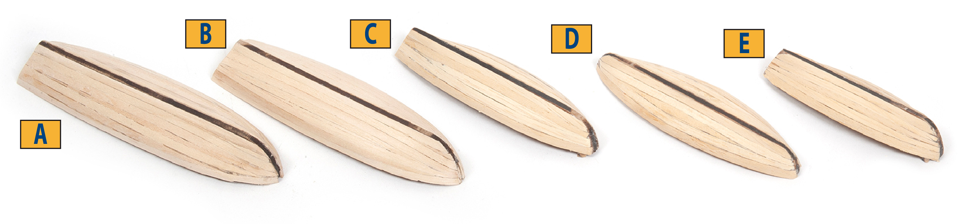
Complete the structure of boat A with parts 8.4 to 8.12.
Step 7
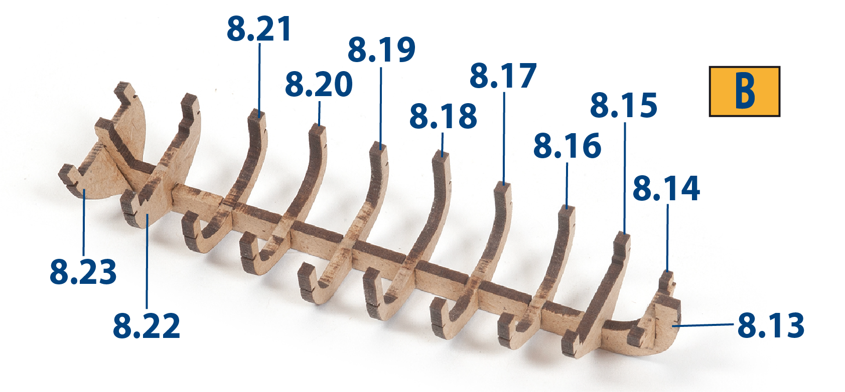
Build boat B with parts 8.13 to 8.23.
Step 8
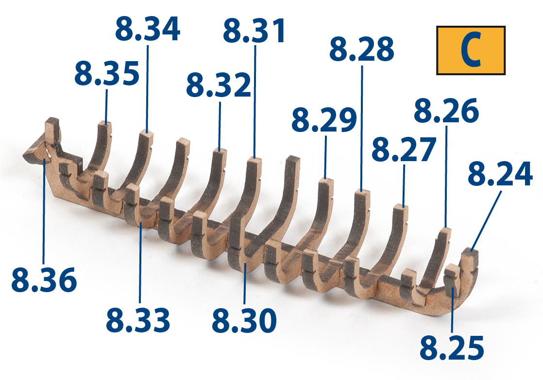
Build boat C with parts 8.24 to 8.36.
Step 9
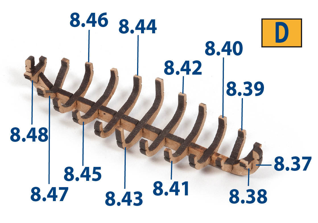
Build boat D with parts 8.37 to 8.48.
Step 10
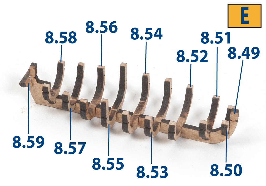
Build boat E with parts 8.49 to 8.59.
Step 11
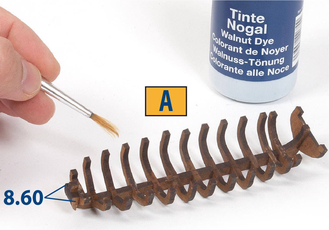
Glue parts 8.60 to boat A as shown. You may want to apply walnut stain to slightly darken the structures.
Step 12
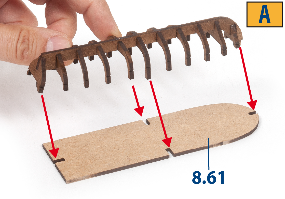
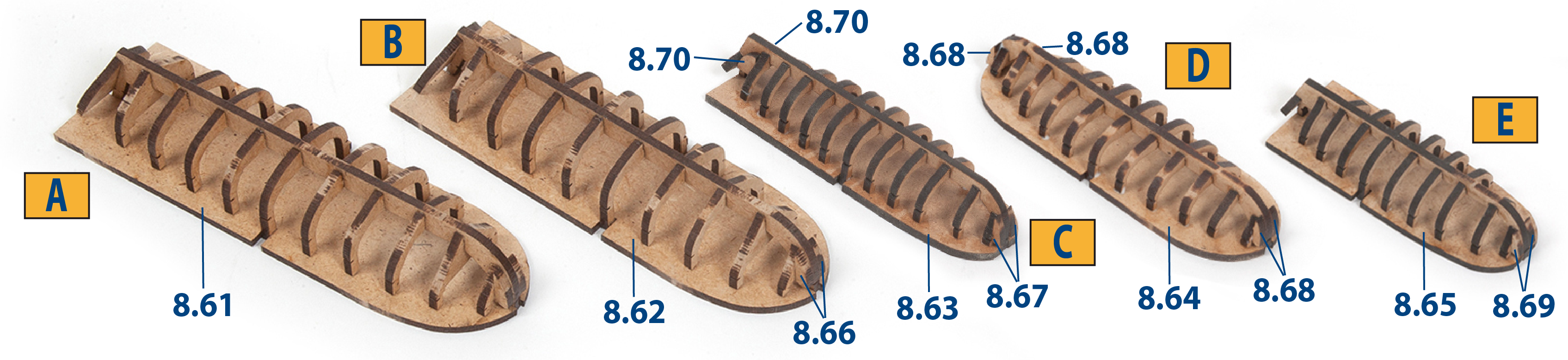
Glue the structure of boat A to part 8.61.
Step 13
Continue to glue parts 8.62 to 8.70 as shown in the image.
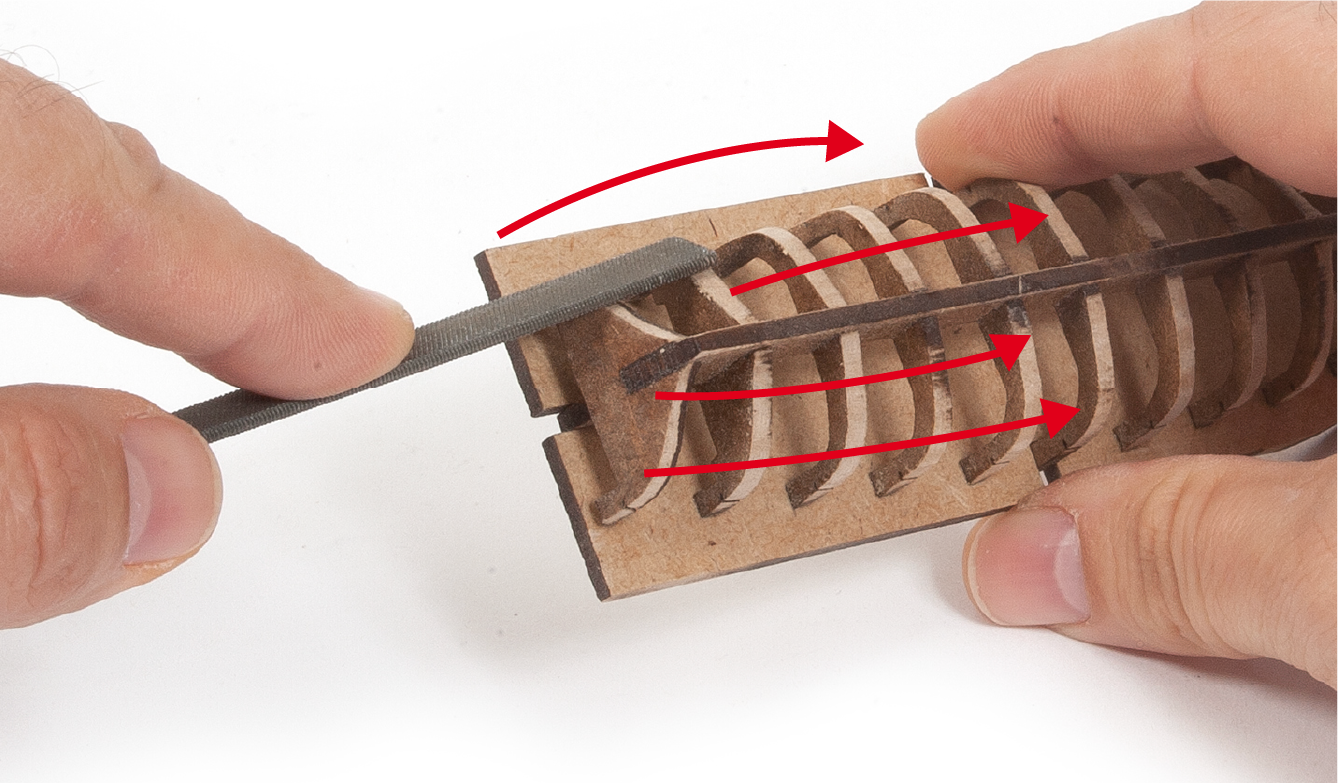
Step 1
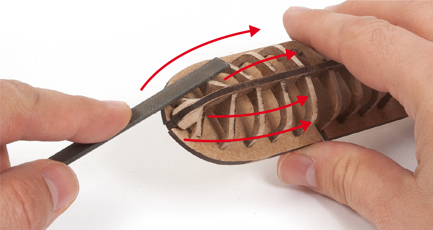
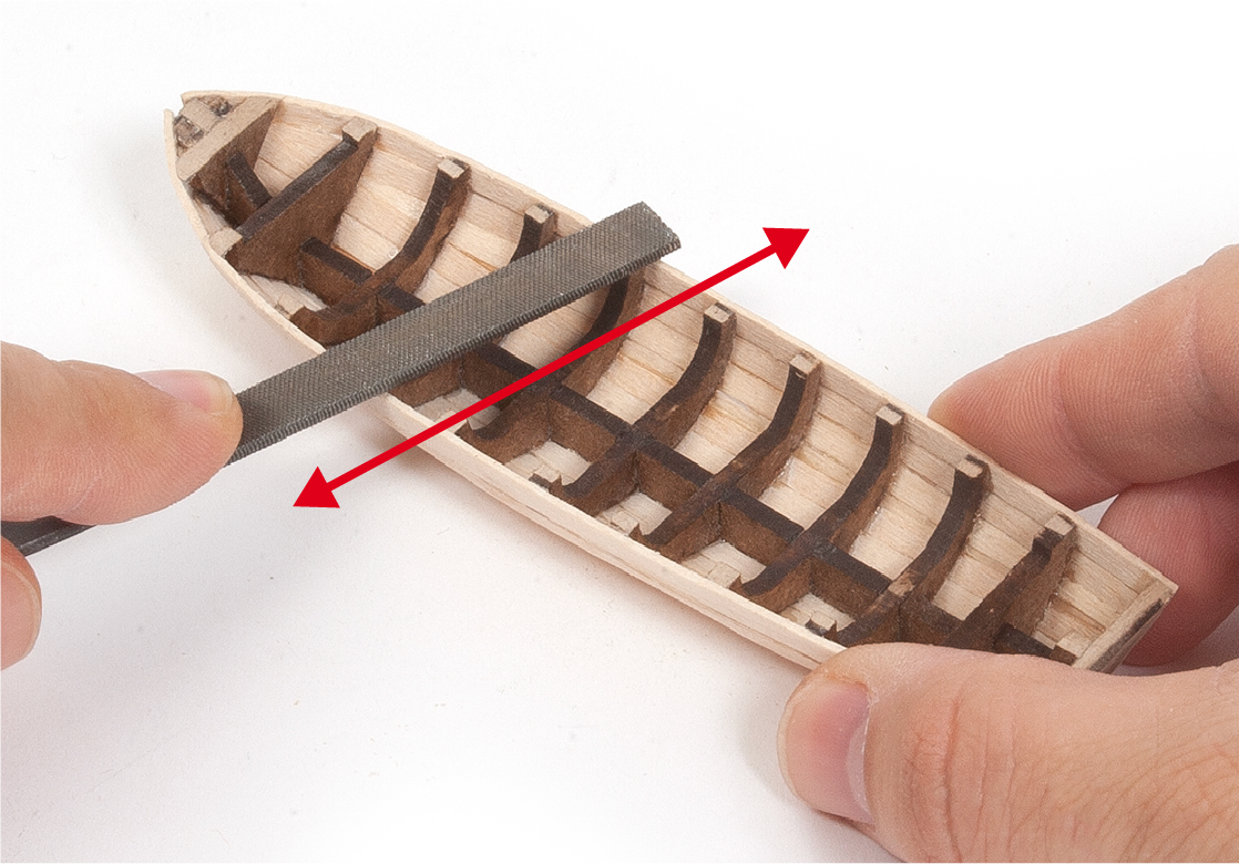
Use a file or sandblock to gently and progressively sand the structures of the five boats until they are smooth.
Step 2
Sand the stern area of the boats in the same way.
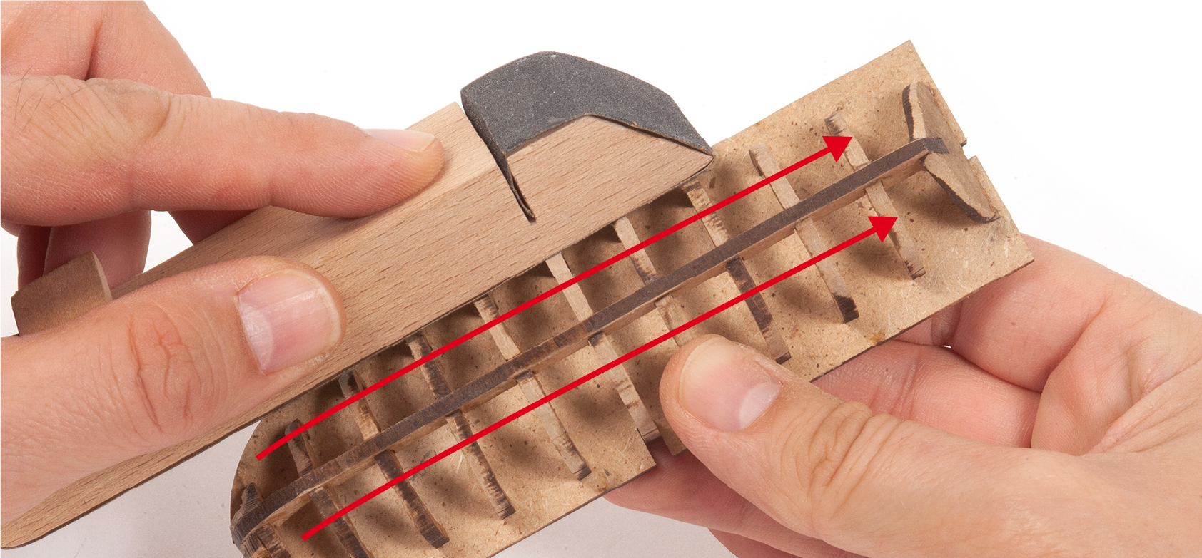
Step 3
Use a slightly wider sandblock for the central part of the boats.
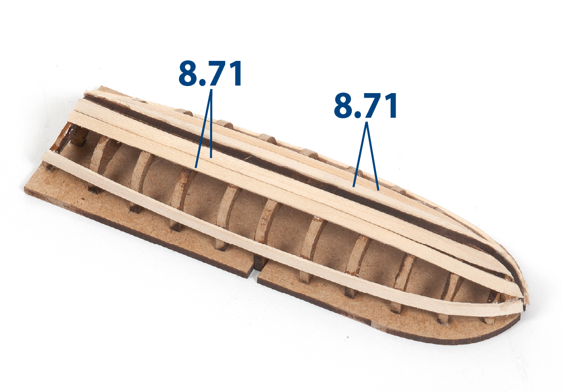
Step 4
Take boat A. Test-fit an 8.71 batten (1 x 30 x 150 mm lime wood) to check the sanding, and correct if necessary. Then, glue the batten precisely along the marks on the boat frames.
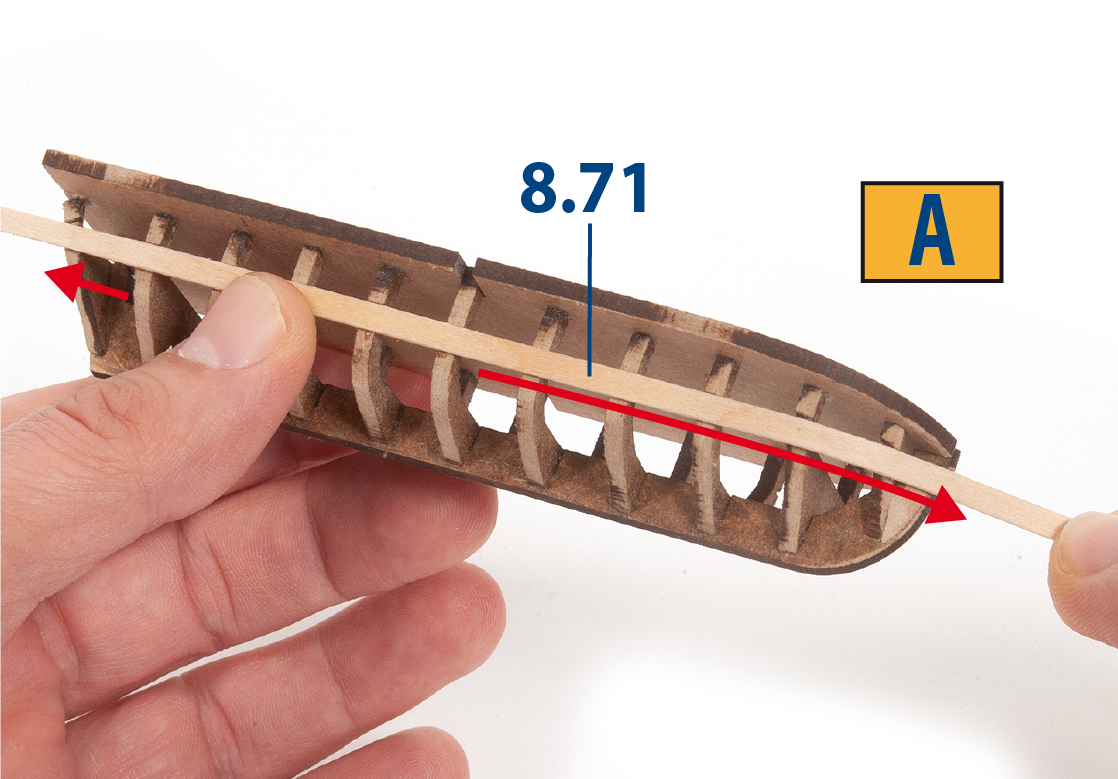
Step 5
Glue another 8.71 batten on the other side of the boat to achieve a symmetrical finish.
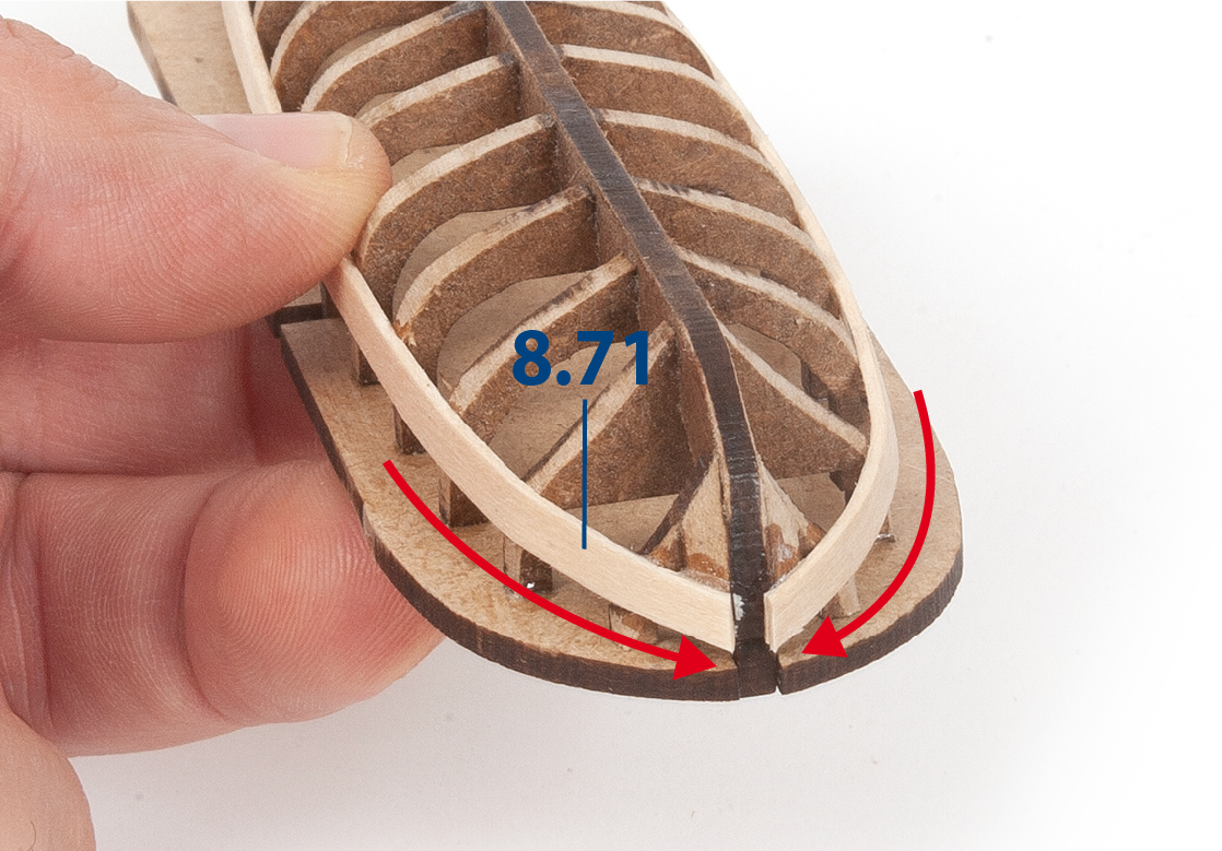
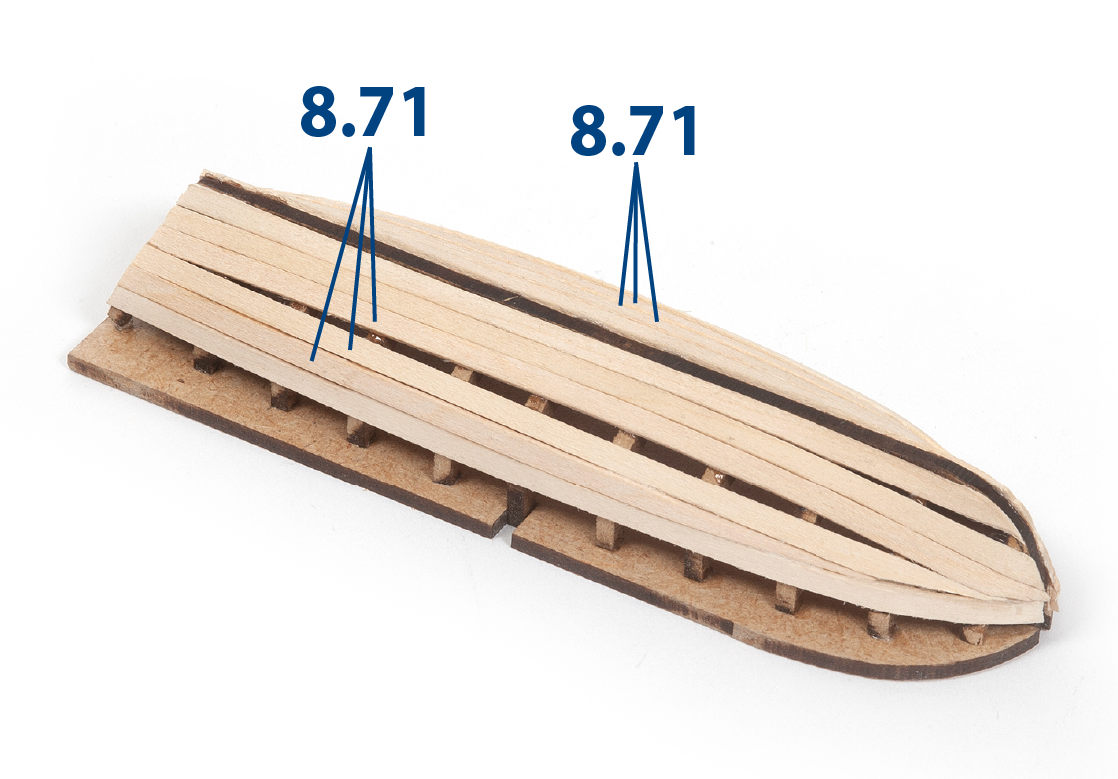
Step 6
Continue gluing battens, but this time starting from the middle of the boat.
Step 7
Continue gluing battens until the gaps are closed.
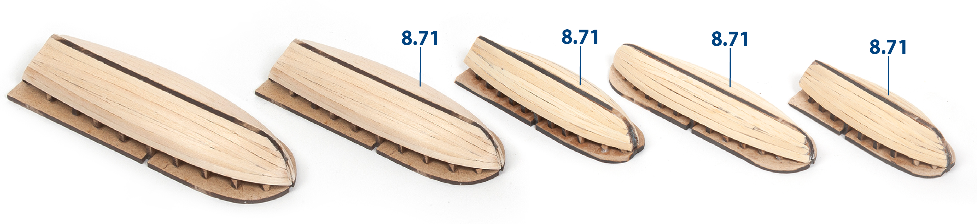
Step 8
Complete the planking of all the boats as shown in the image.
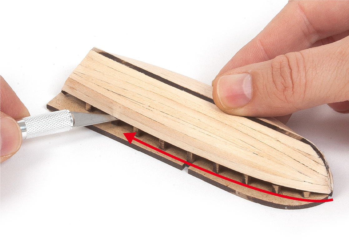
Step 9
Cut along the notches on the frames to separate the boats from their supports.
Step 10
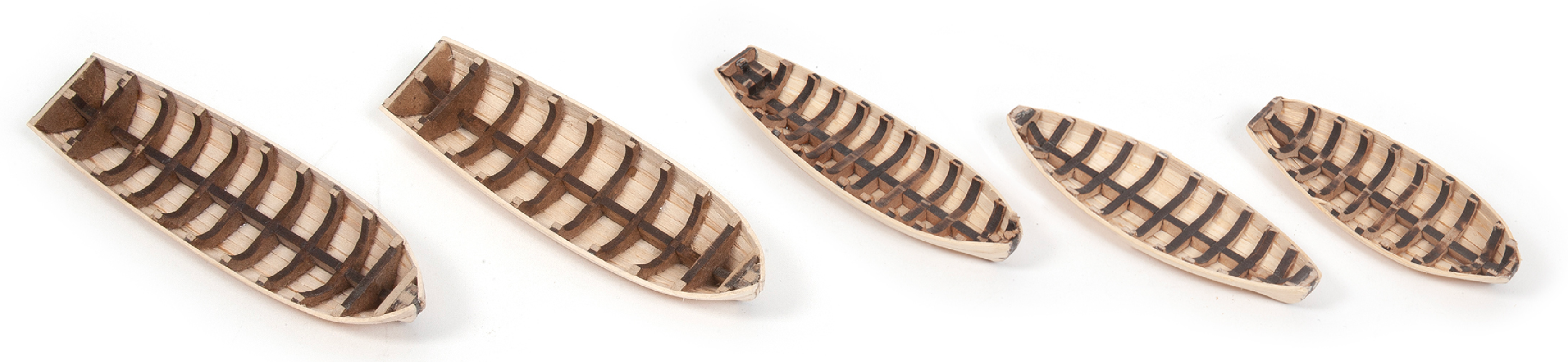
This image shows the planking of the five boats, once complete.
Step 11
Smooth the top of the boats with a file.
Step 12
The five boats should now look like this.
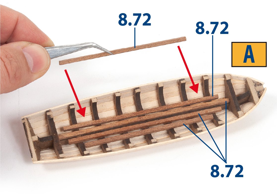
Step 1
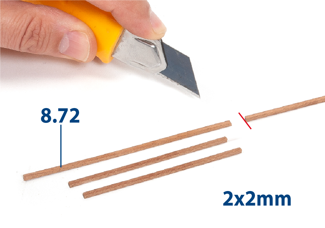
Take boat A. Cut parts 8.72 (2 x 2 mm mahogany) to match the lengths on boat A as shown, then glue them in place.
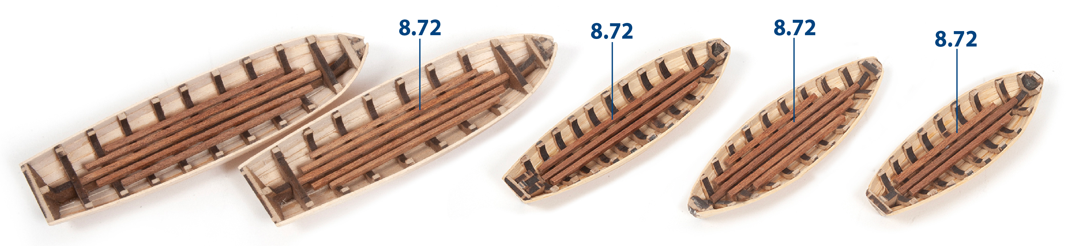
Step 2
Continue to fit parts 8.72 to the remaining boats as shown.
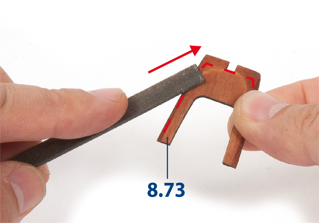
Step 3
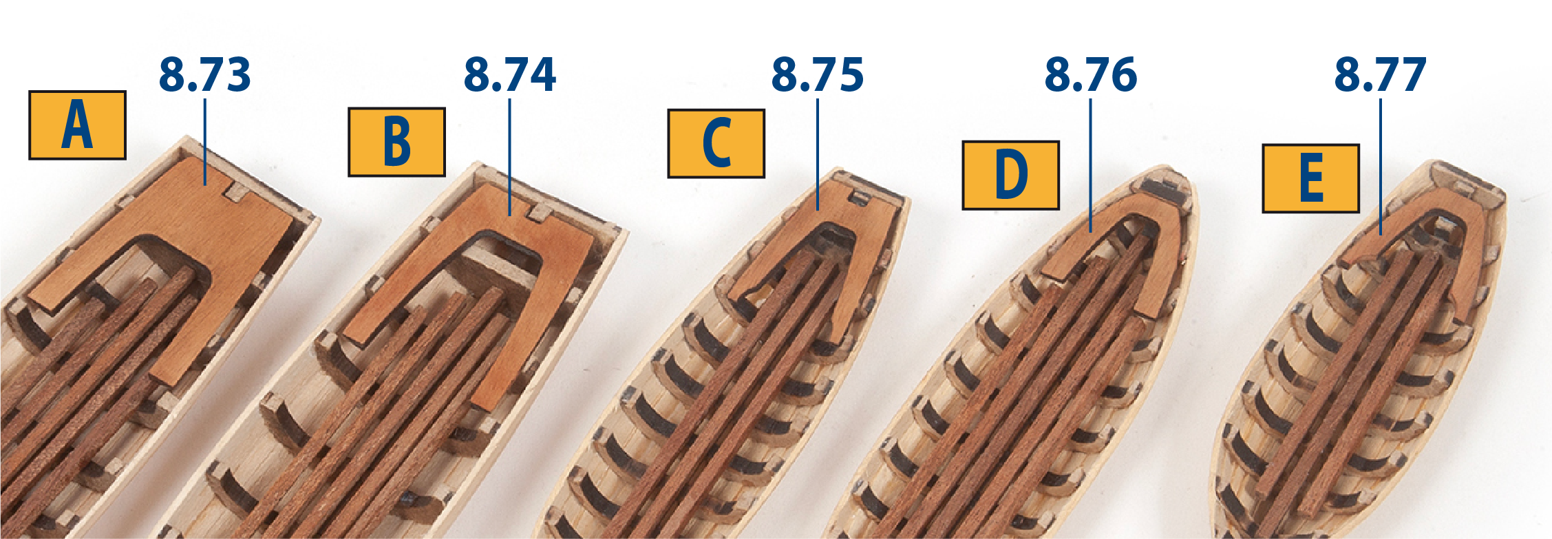
File part 8.73 and adjust the frames to achieve a good fit.
Step 4
Glue part 8.73 in place, then repeat this process for parts 8.74 to 8.77.
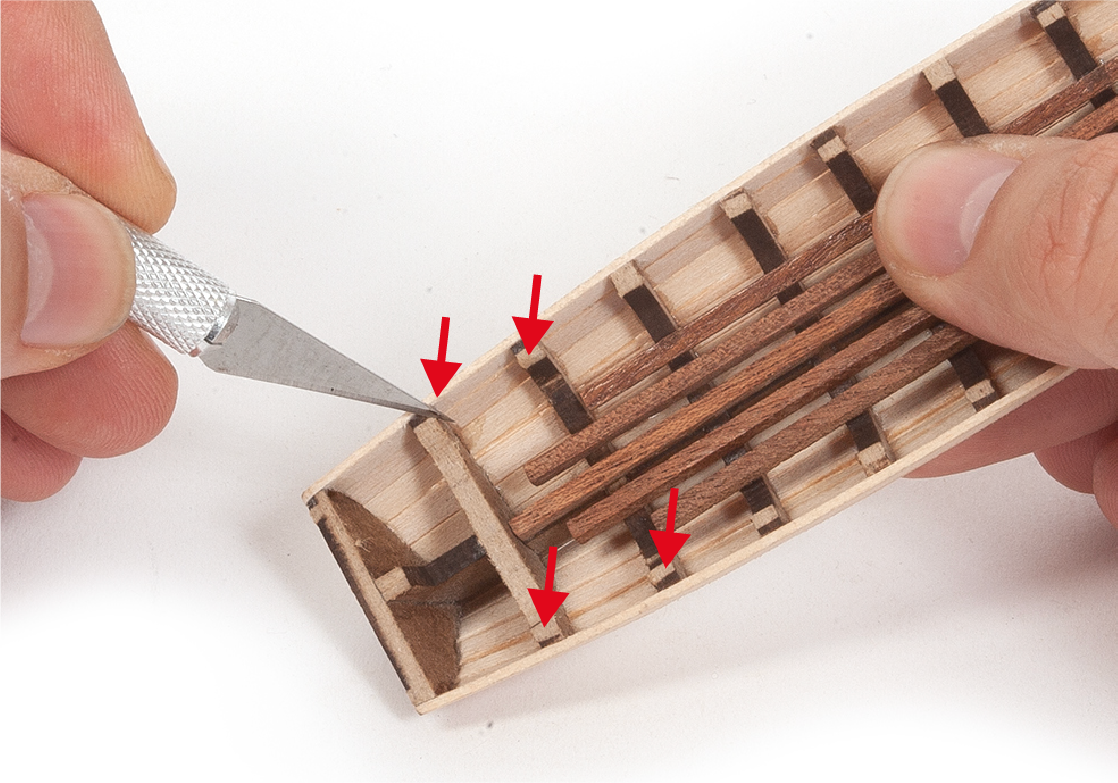
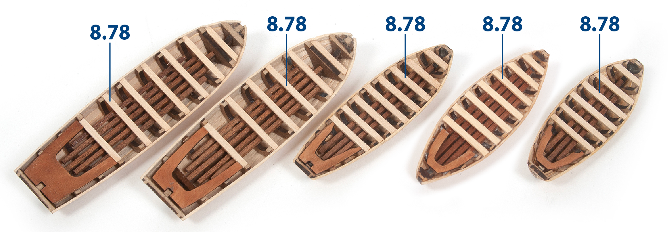
Step 5
Cut to length and glue parts 8.78 (1 x 3 mm lime wood) to the boats as shown.
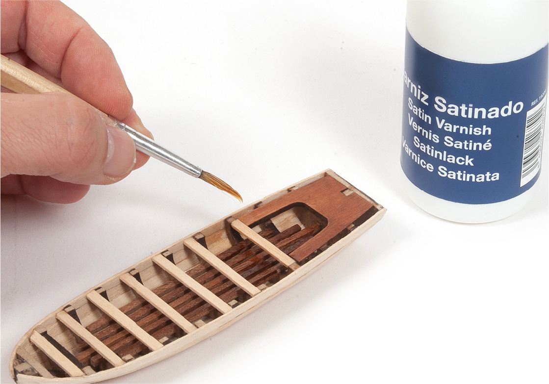
Step 6
Apply varnish to all the parts you have added to the boats.
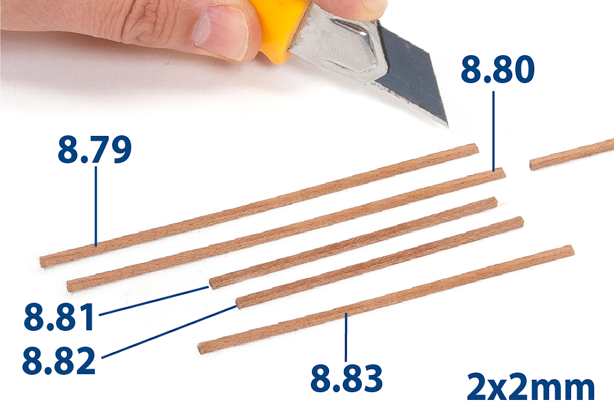
Step 1
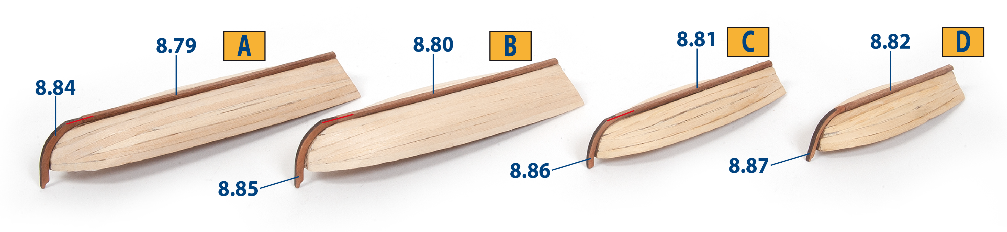
Cut to length parts 8.79 to 8.83 (2 x 2 mm mahogany).
| 8.79: 106 mm | 8.82: 60 mm |
| 8.80: 100 mm | 8.83: 81 mm |
| 8.81: 71 mm |
Step 2
Glue parts 8.79 to 8.87 as shown.
Step 3
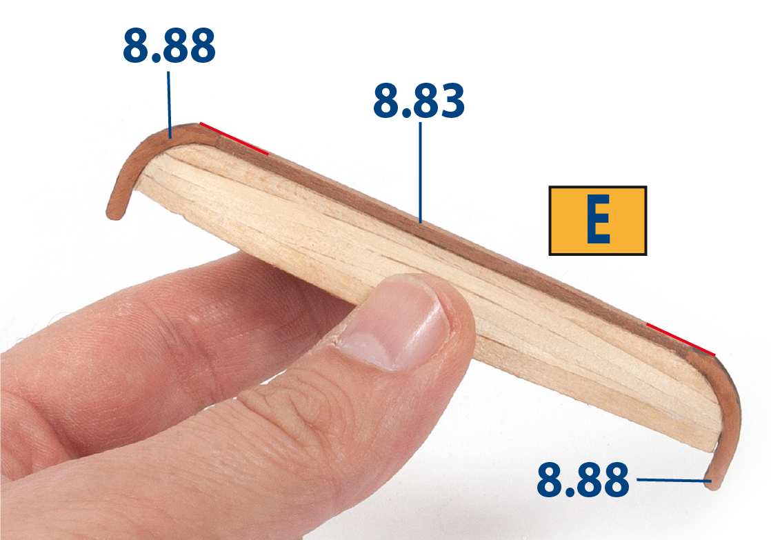
Glue together parts 8.88 and 8.83.
Step 4
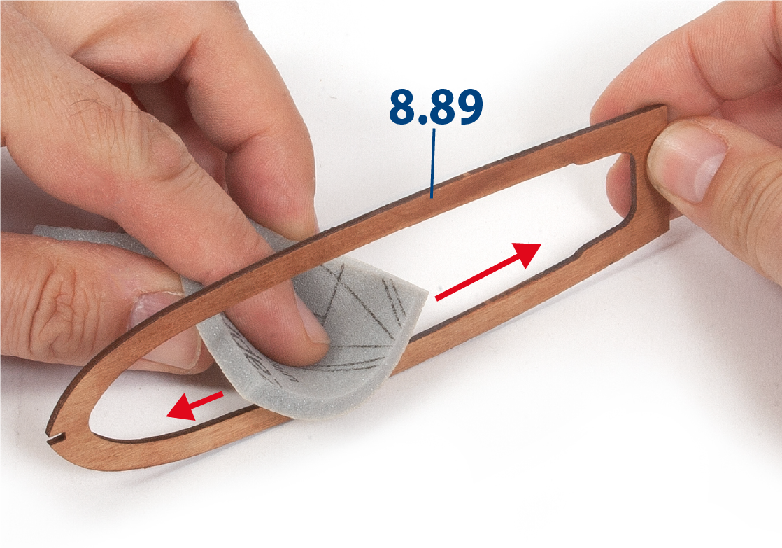
Use a sanding sponge to smooth part 8.89.
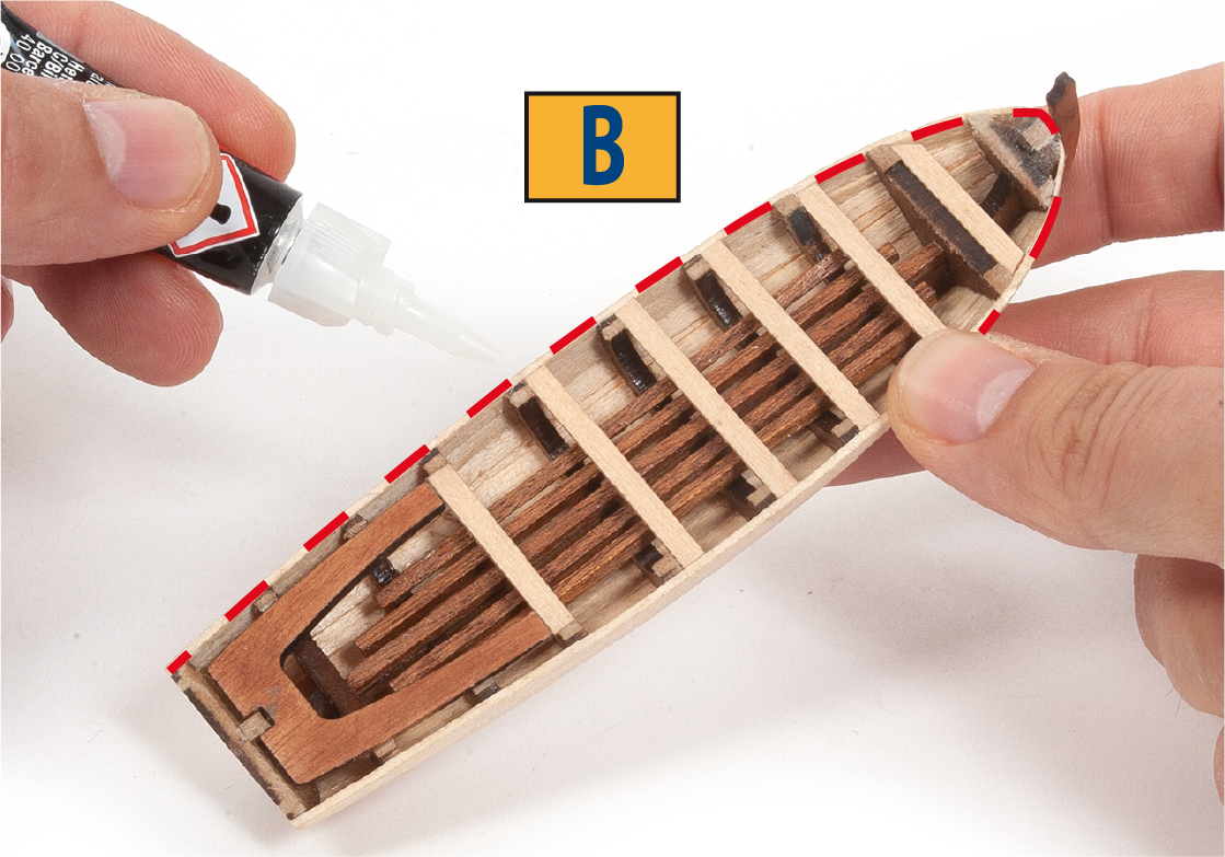
Step 5
Take boat B. Apply super glue to the rim of the boat as shown, then centre and fit part 8.89.
Step 6
Fit parts 8.90 to 8.93 using super glue.
Step 7
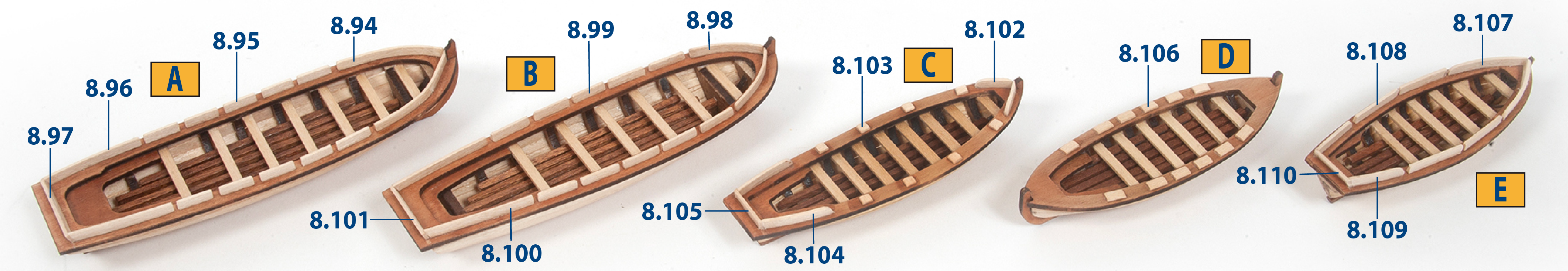
Cut parts 8.94 (1 x 3 x 37 mm lime wood) and 8.95 (1 x 3 x 10 mm lime wood) to size (see table below), then sand their edges with a sanding sponge.
Step 8
Glue parts 8.94 and 8.95 to boat A as shown.
Then cut and glue parts 8.96 to 8.110 (1 x 3 mm lime wood) to the boats as shown.
| A | B | C | D | E |
| 8.94: 37 mm | 8.98: 25 mm | 8.102: 12 mm | 8.106: 6 mm | 8.107: 24 mm |
| 8.95: 10 mm | 8.99: 12 mm | 8.103: 3 mm | 8.108: 17 mm | |
| 8.96: 30 mm | 8.100: 32 mm | 8.104: 22 mm | 8.109: 19 mm | |
| 8.97: 26 mm | 8.101: 23 mm | 8.105: 15 mm | 8.110: 14 mm |
Step 1
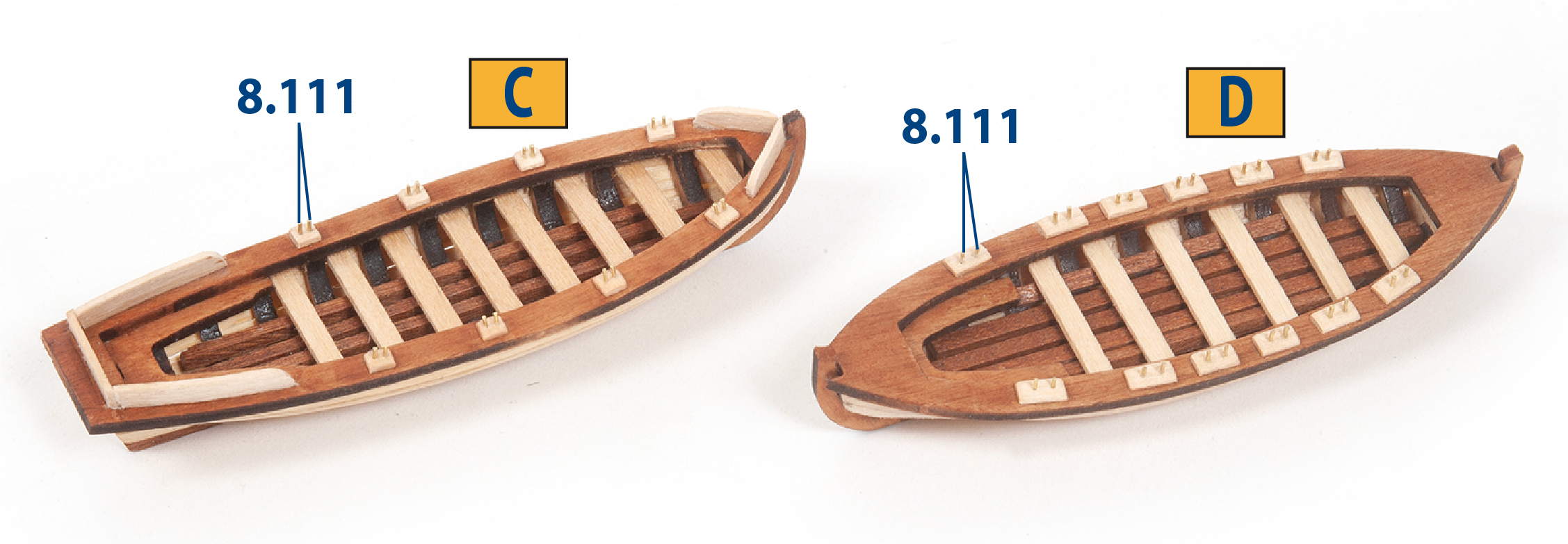
Cut to size parts 8.111 (ø0.50 x 4 mm). Drill holes in parts 8.103 (boat C) and parts 8.106 (boat D), then insert and glue parts 8.111 as shown.
Step 2
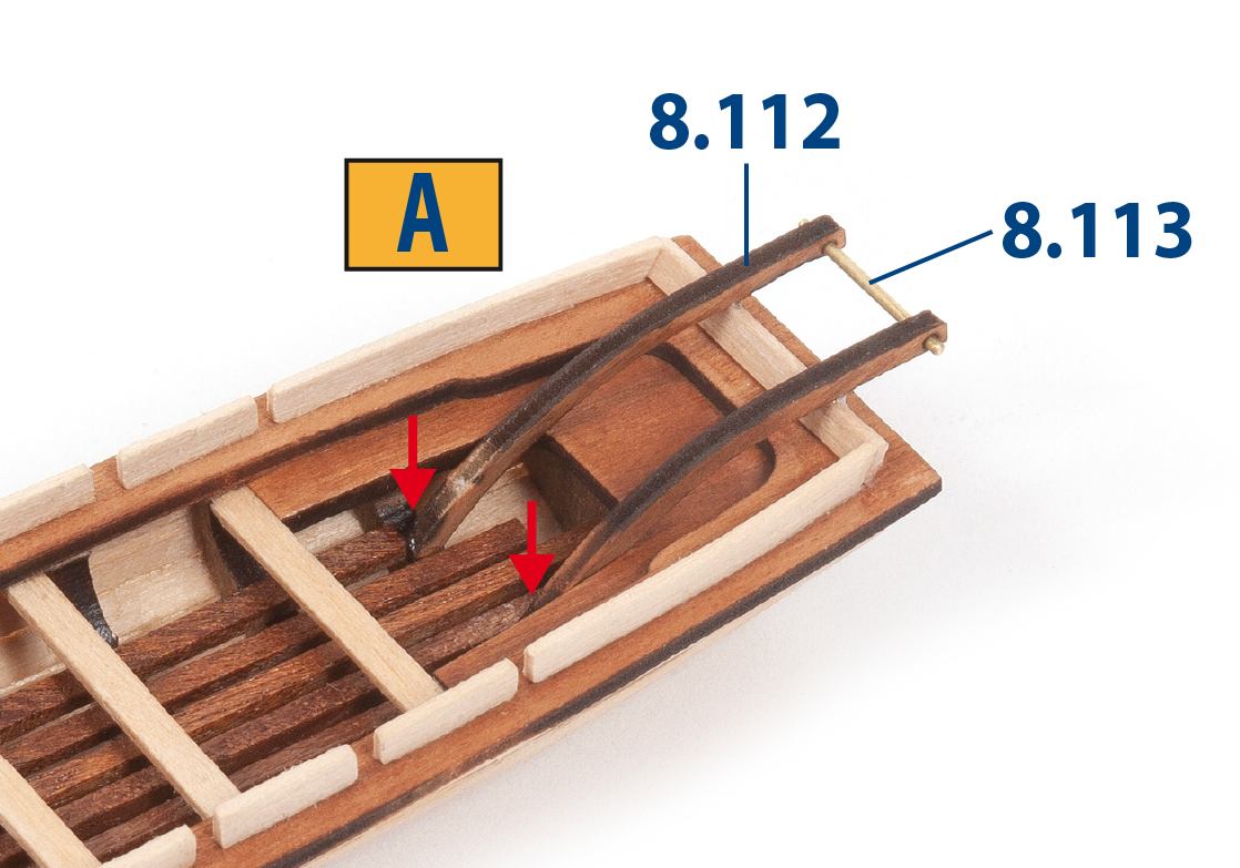
Fit and glue parts 8.112 and 8.113 (ø1 x 16 mm) to boat A.
Step 3
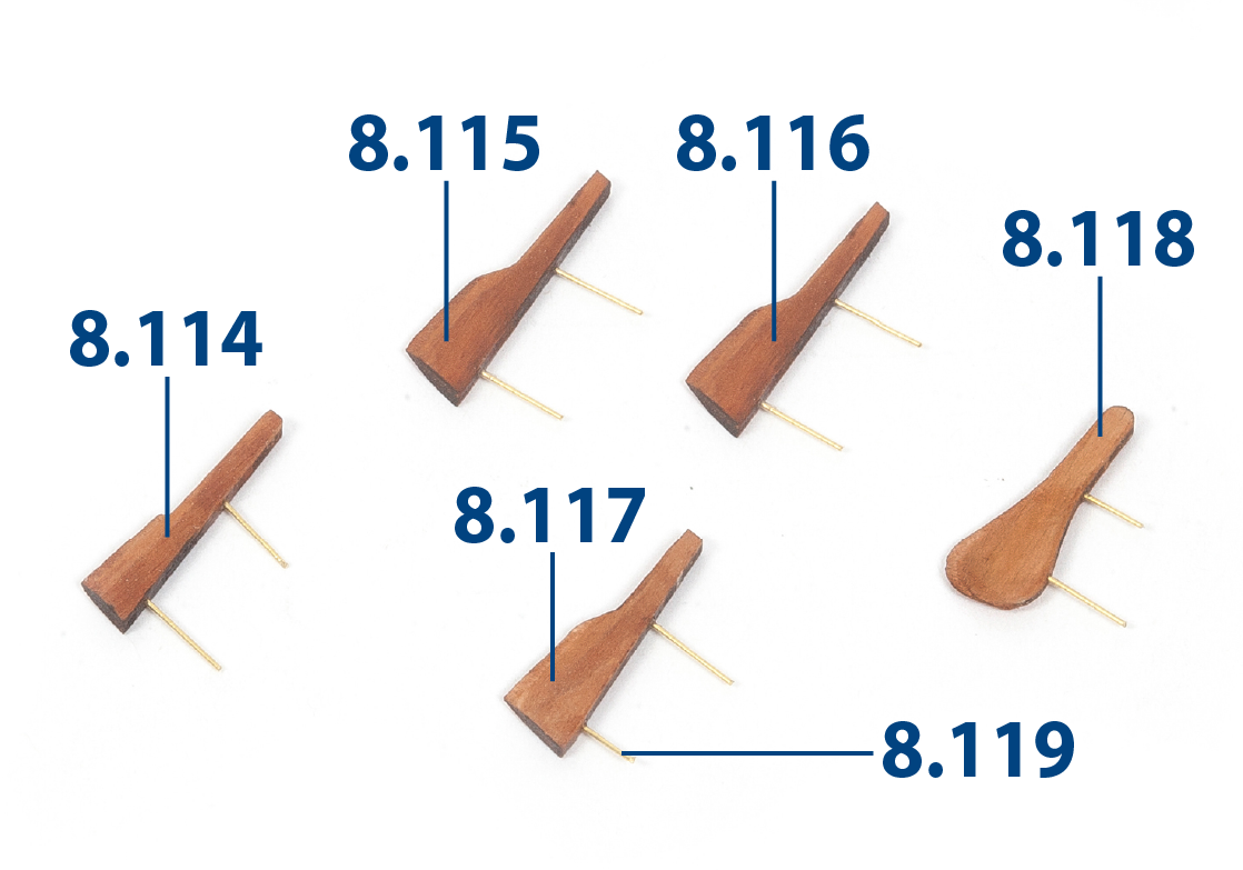
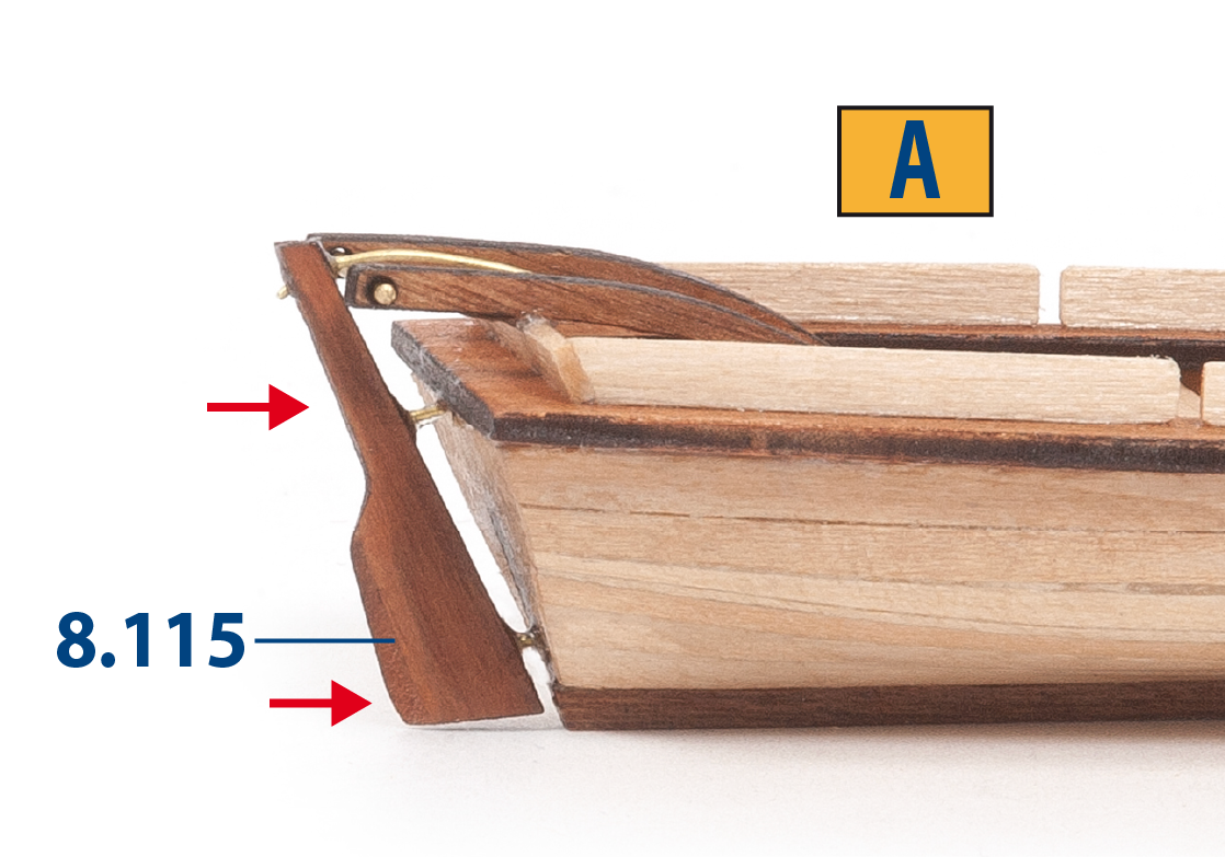
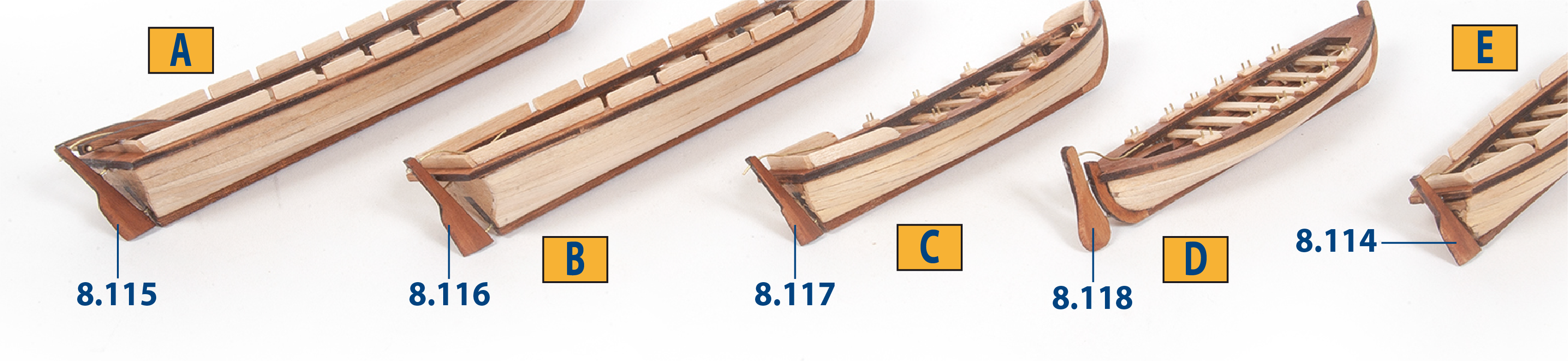
Sand the rudders 8.114 to 8.118. Drill three ø0.50 mm holes in each rudder. Insert and glue parts 8.119 to each rudder. The third hole is for the tiller - see steps 4 and 5 for guidance.
Step 4
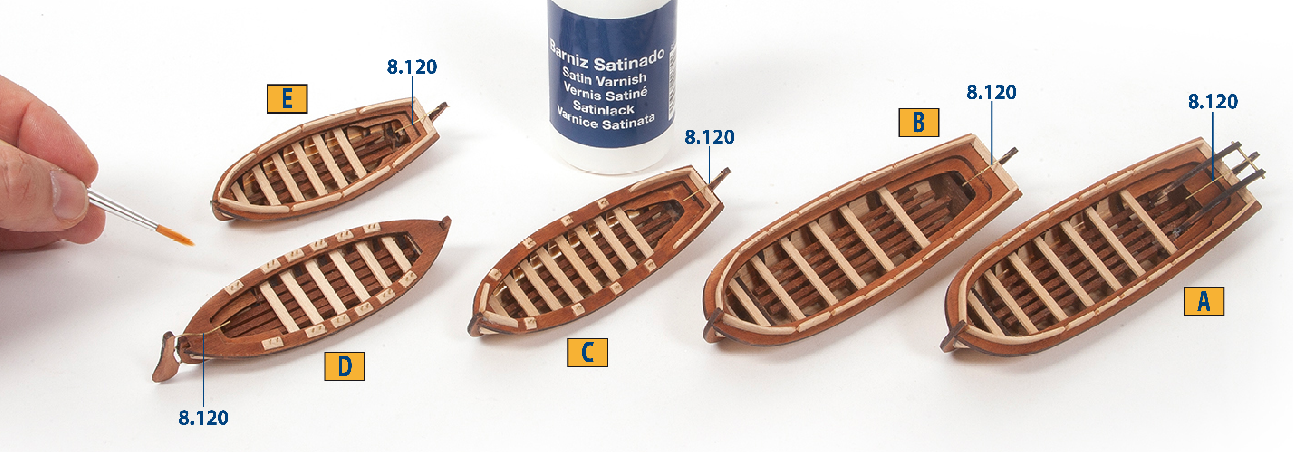
Cut part 8.120 (ø0.50 x 32 mm) to make the tiller and glue into place. Drill two ø0.50 mm holes in boat A, then glue rudder 8.115 in place. After the glue has dried, shape the tiller.
Step 5
Cut parts 8.120 (ø0.50 x 32 mm) to make the tillers, then glue to the rudder. Fit the rudders to the remaining boats as shown, then shape the tillers.
Step 6
Once the glue has dried, varnish the boats.
Step 1
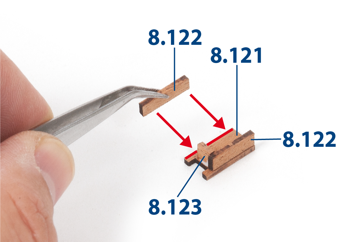
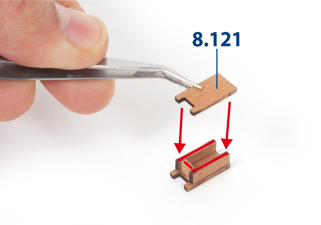
Glue parts 8.121 to 8.123 together.
Step 2
Glue part 8.121 as shown. Repeat this process to make a second assembly.
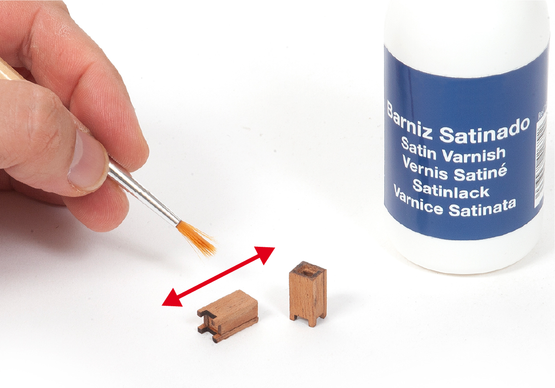
Step 3
Sand and varnish the two assemblies.
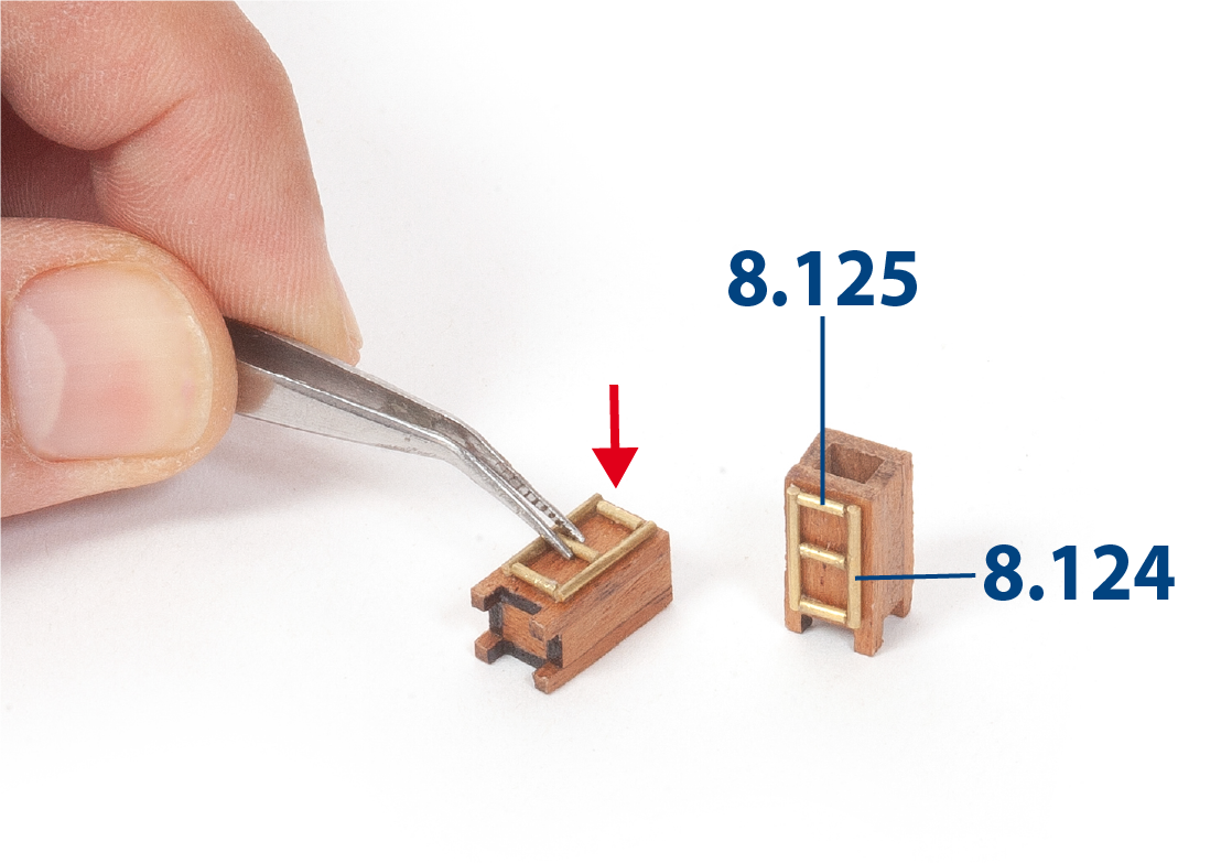
Step 4
Cut to size parts 8.124 (ø1 x 12 mm) and 8.125 (ø1 x 5 mm). Glue parts 8.124 and 8.125 to part 8.121 on the two assemblies as shown.
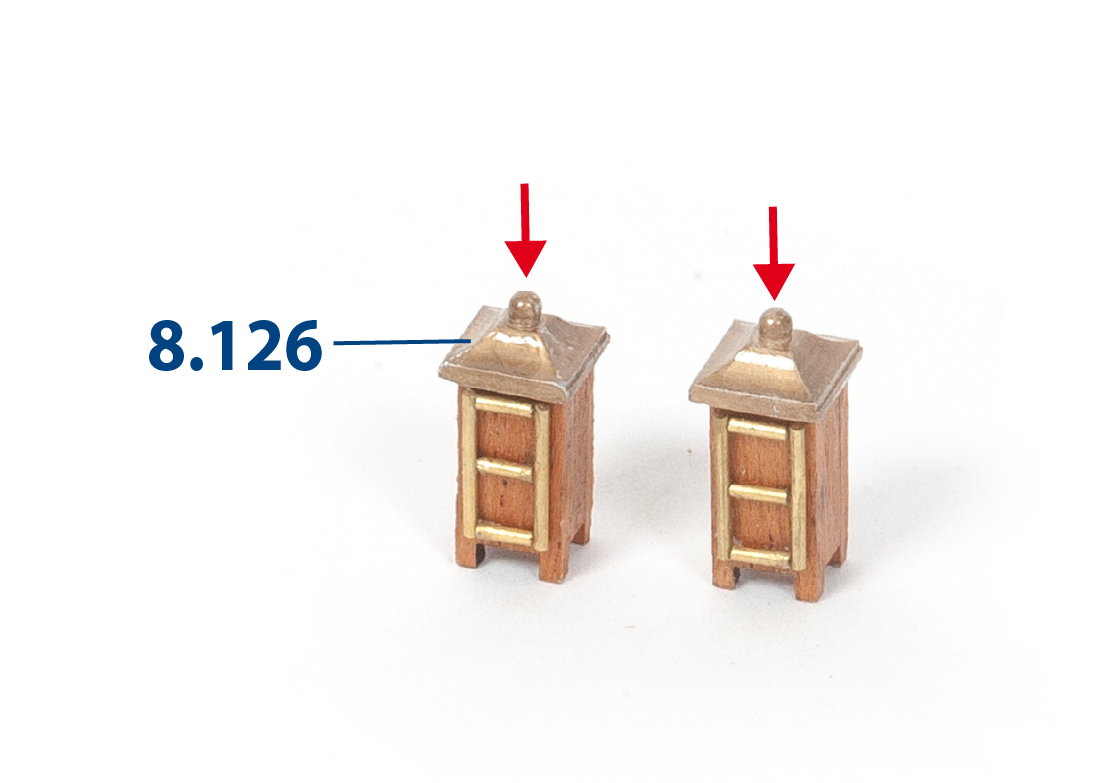
Step 5
Glue parts 8.126 to the assemblies.
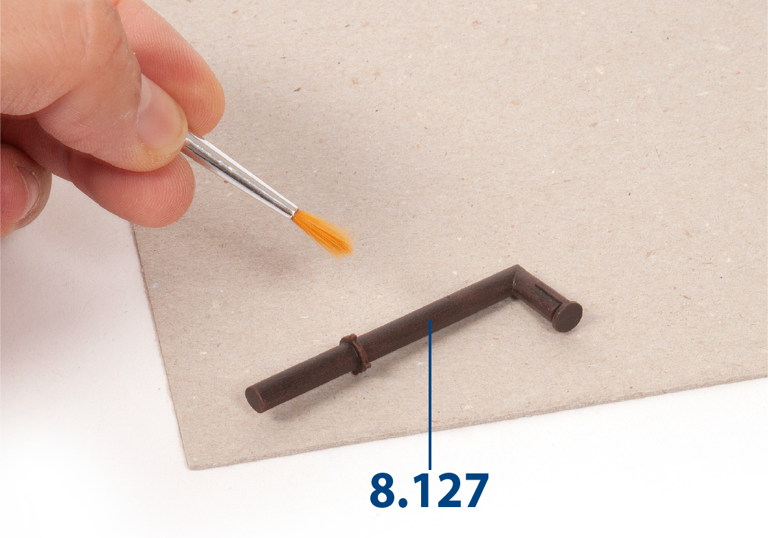
Step 6
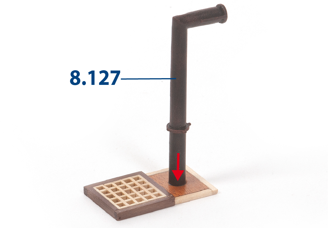
Paint part 8.127 black, then drybrush with red paint.
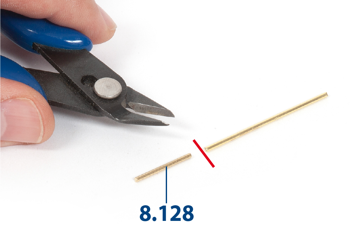
Step 7
Cut to length part 8.128 (ø1.5 x 16 mm).
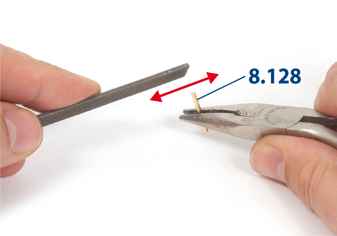
Step 8
Smooth the ends of part 8.128 using a file.
Step 9
Paint parts 8.129 and 8.130 black, then drybrush with red paint.
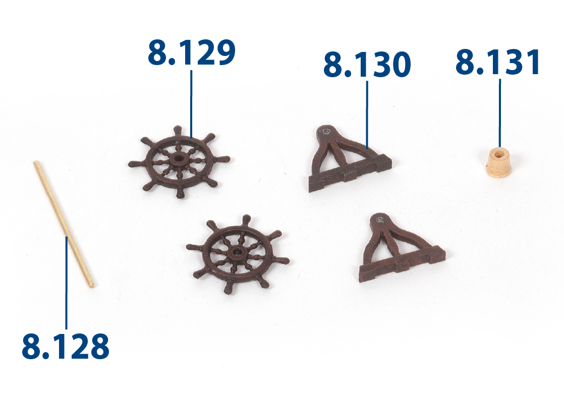
Step 10
Fit parts 8.128 to 8.131 together.
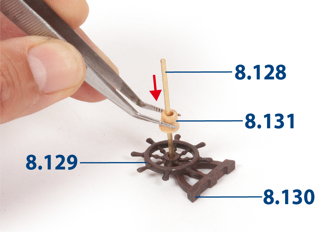
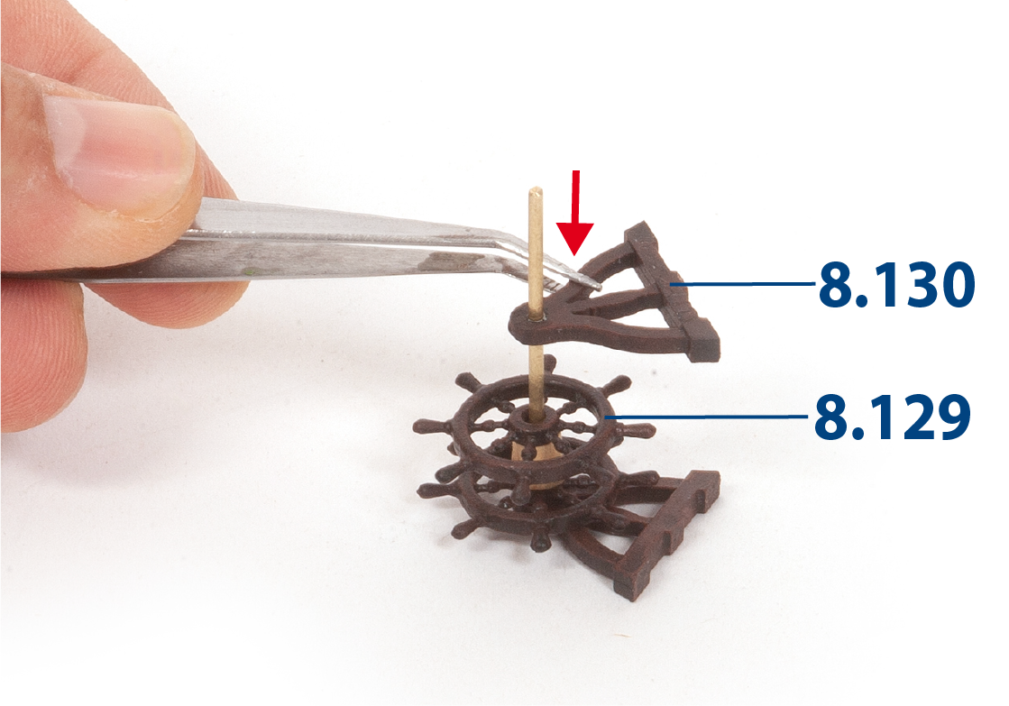
Step 11
Fit parts 8.129 and 8.130. Apply glue to part 8.130 to hold it in place.
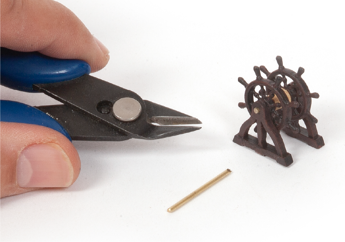
Step 12
Apply glue to the other side of the assembly then cut part 8.128 flush.
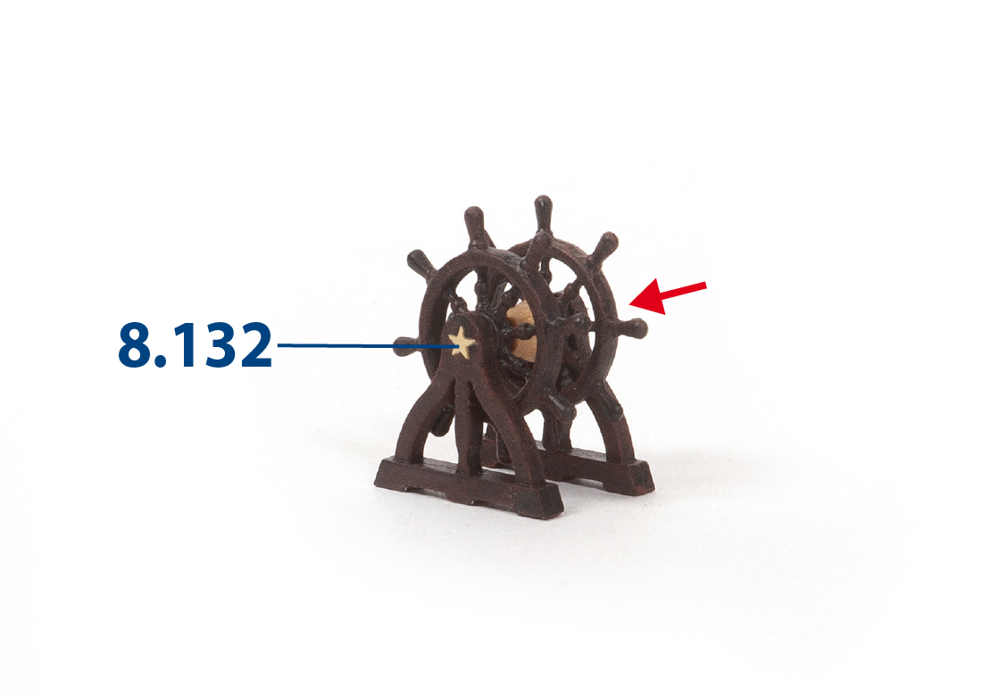
Step 13
Glue parts 8.132 (from sheet 2001-23, supplied with pack 4) to each end of part 8.128.
Step 14
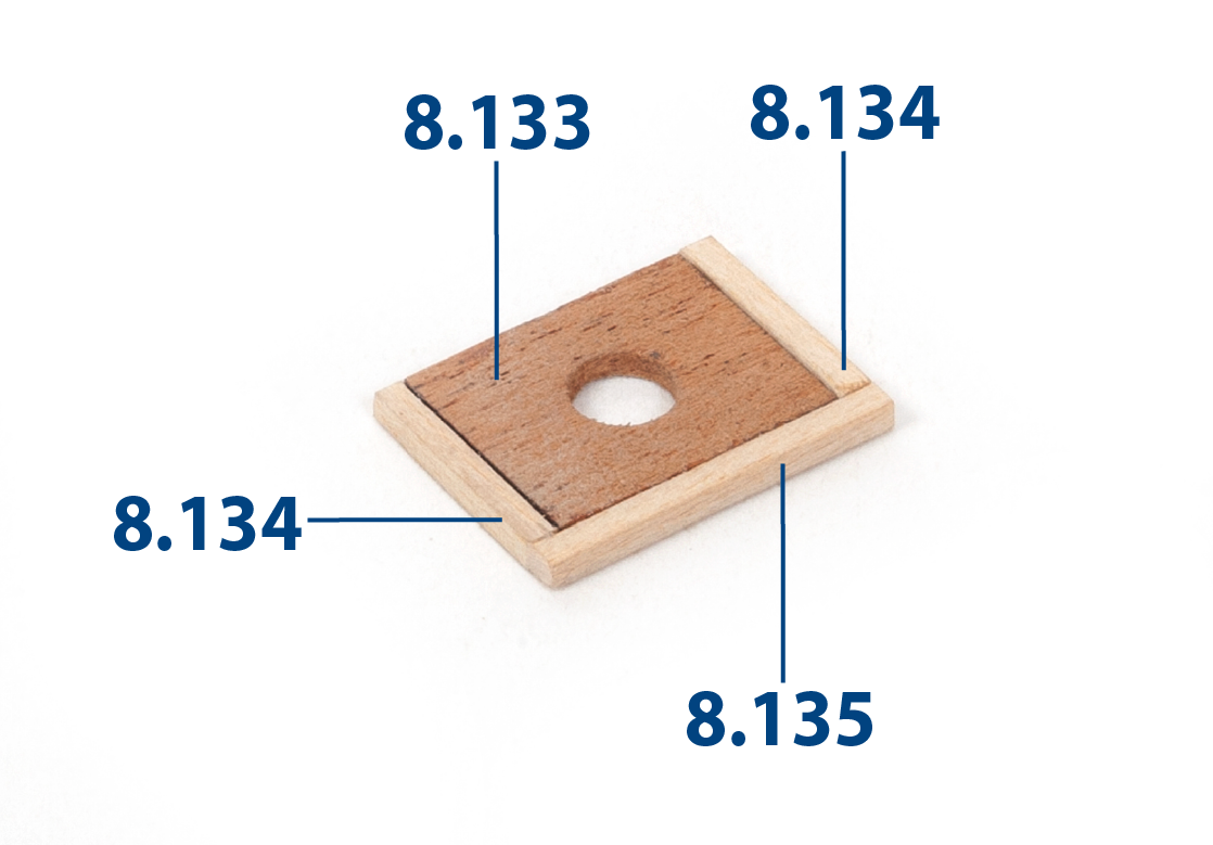
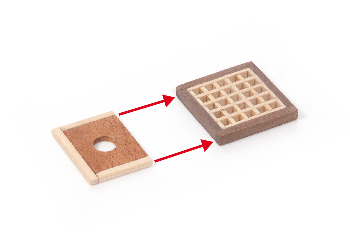
Glue parts 8.134 (2 x 2 x 15 mm lime wood) and 8.135 (2 x 2 x 22 mm lime wood) to part 8.133. Varnish the assembly after the glue has dried.
Step 15
Glue the assembly to the part you built in pack 6, stage 26.
Step 16
Insert and glue part 8.127 (step 6).
Step 1
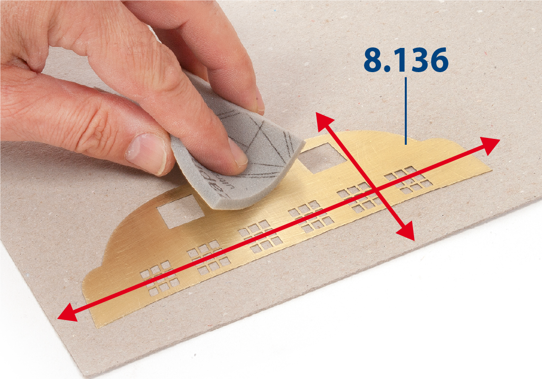
Sand the back of part 8.136 (supplied with pack 4) to roughen it.
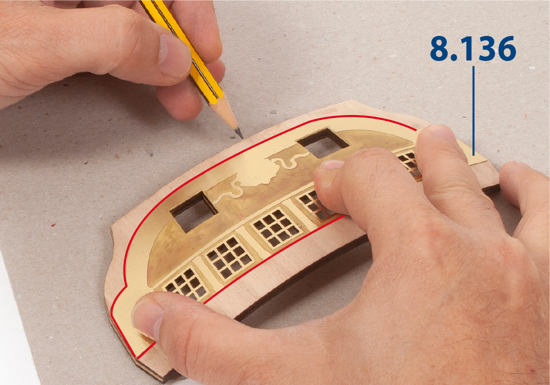
Step 2
Place part 8.136 on the transom (stage 32), centring it with the windows. Use a pencil to trace the outline of part 8.136 onto the transom.
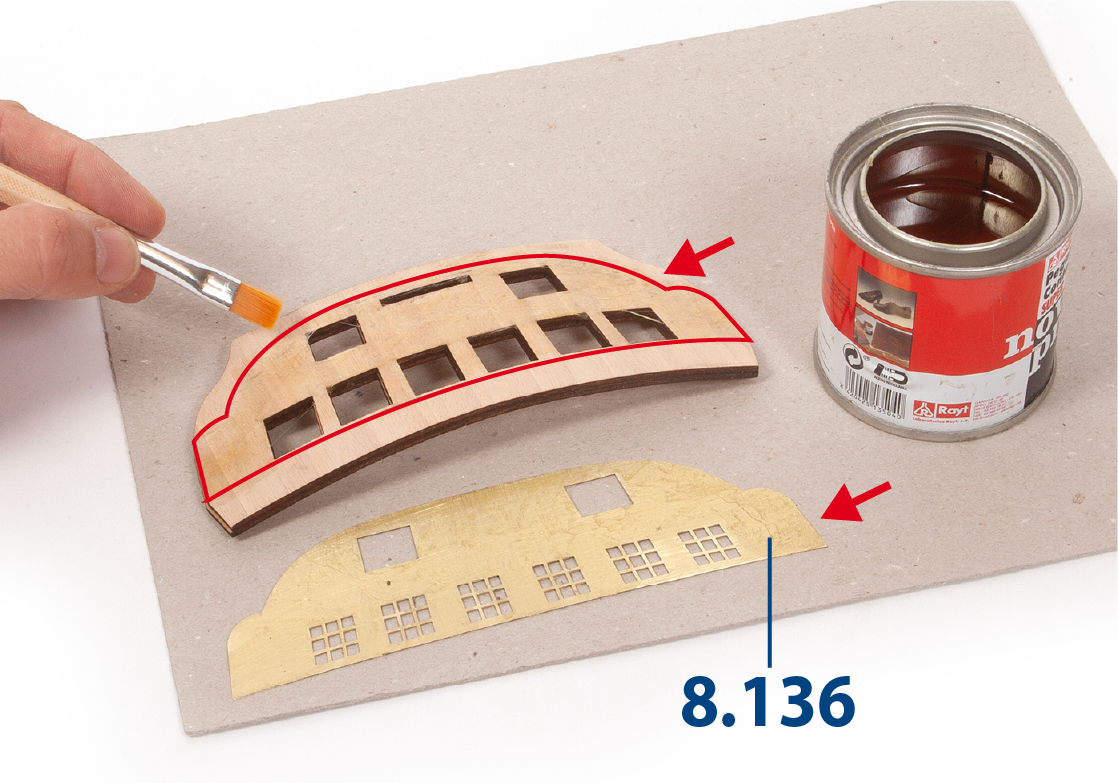
Step 3
Apply contact adhesive to the marked area of the transom and to the back of part 8.136.
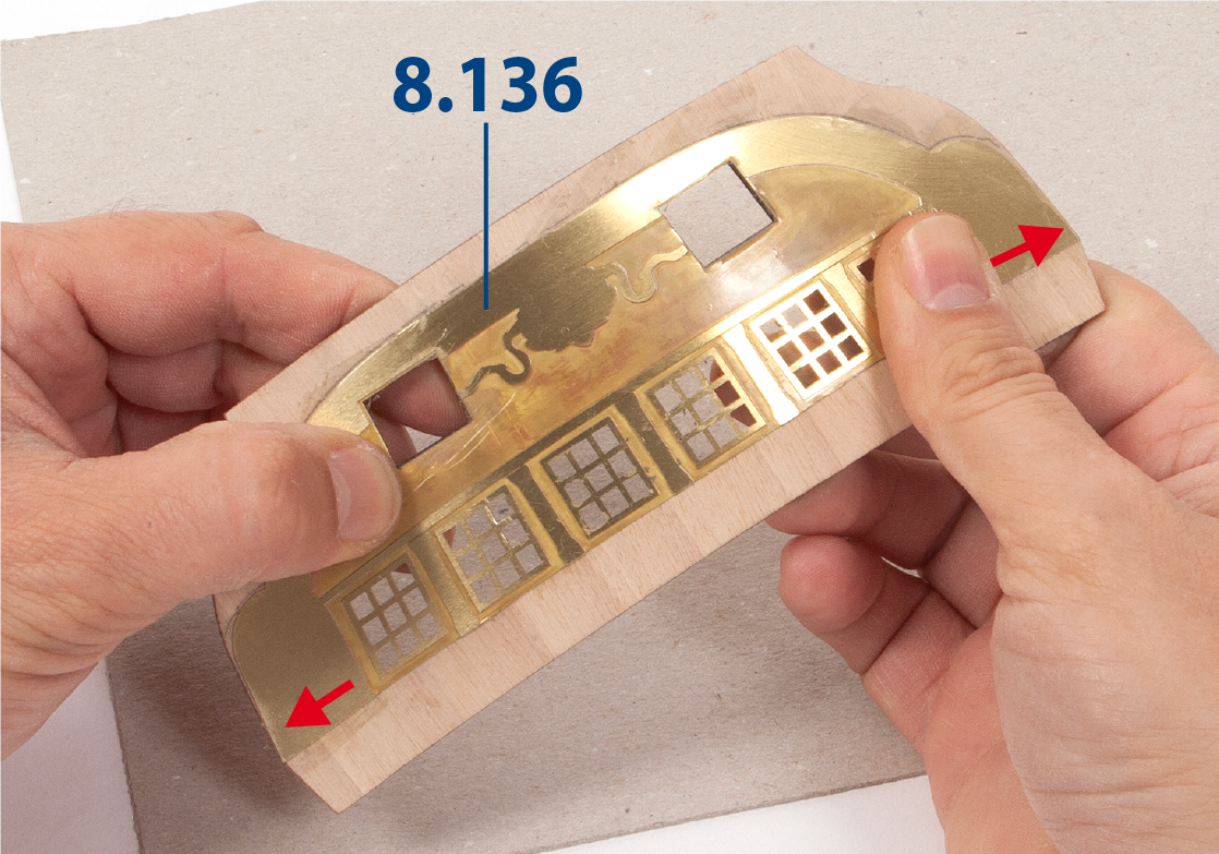
Step 4
When the glue no longer sticky, press part 8.136 firmly against the transom so that it adheres properly.
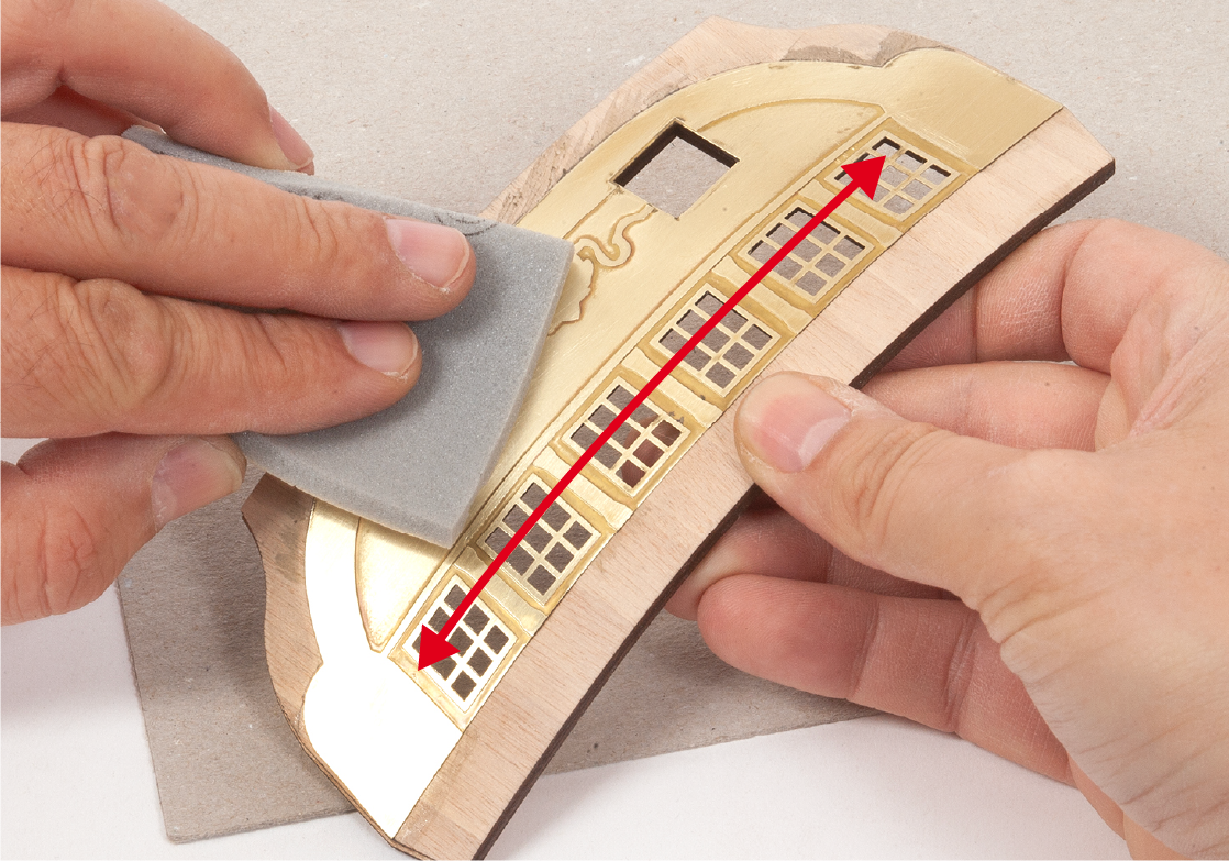
Step 5
Smooth the entire surface of the parts with fine-grit sponge sandpaper and remove any residue.
Step 6
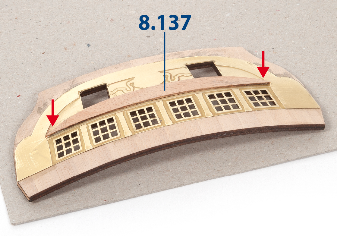
Use contact adhesive to glue part 8.137 in place.
Step 7
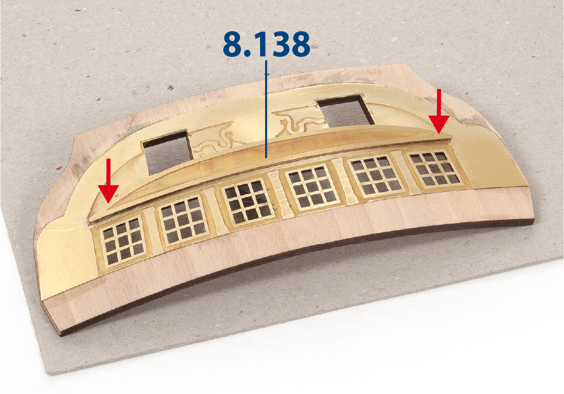
Sand then glue part 8.138 (pack 4) centred on part 8.137.
Step 8
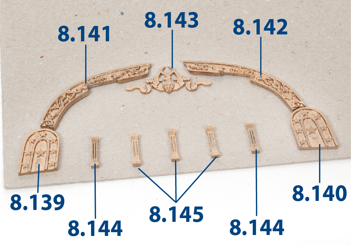
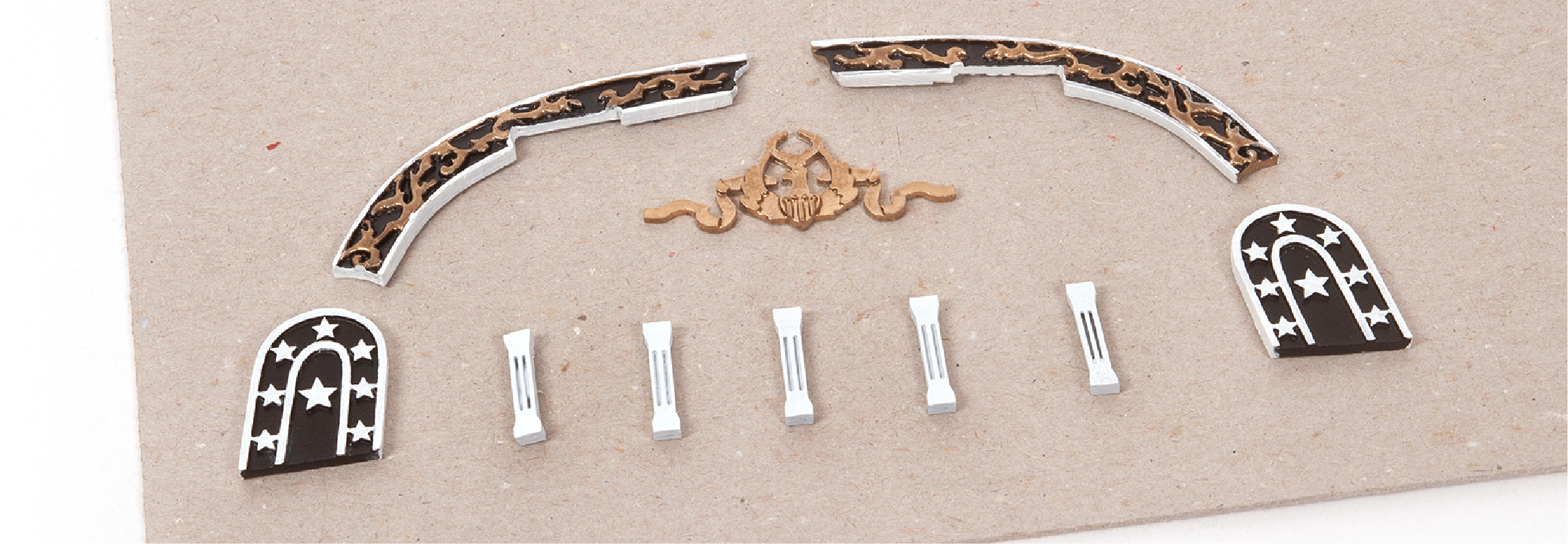
The image shows the parts needed to decorate the transom. Decide whether you want to paint them or not before gluing the parts.
Step 9
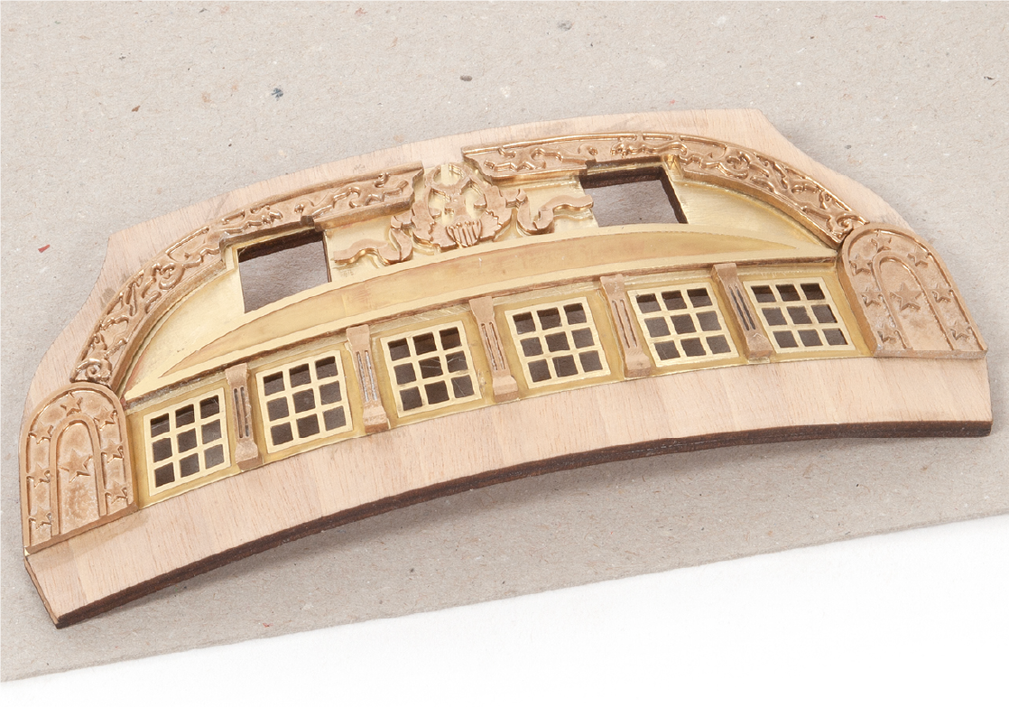
This image shows you how the parts will be placed on the transom, but do not glue them yet.
Step 10
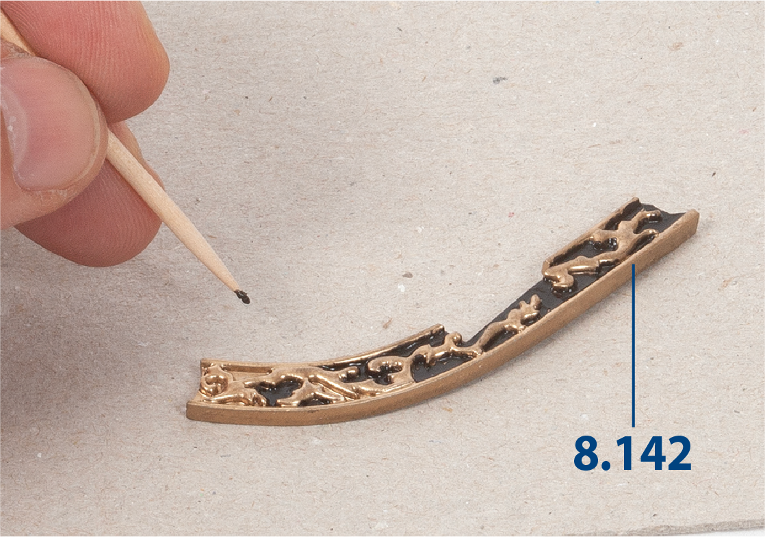
Paint the recesses of part 8.142 with black paint. Use a fine paintbrush or toothpick.
Step 11
Paint the parts that decorate the transom with the colours black and white as shown in the image.
Step 12
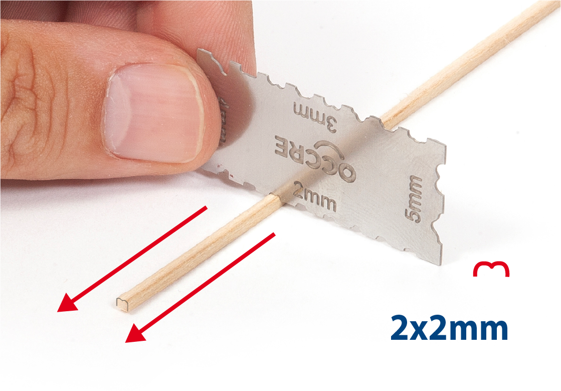
Take a 2 x 2 mm strip of lime wood and use a moulding scriber tool to create the shape shown in the image.
Step 13
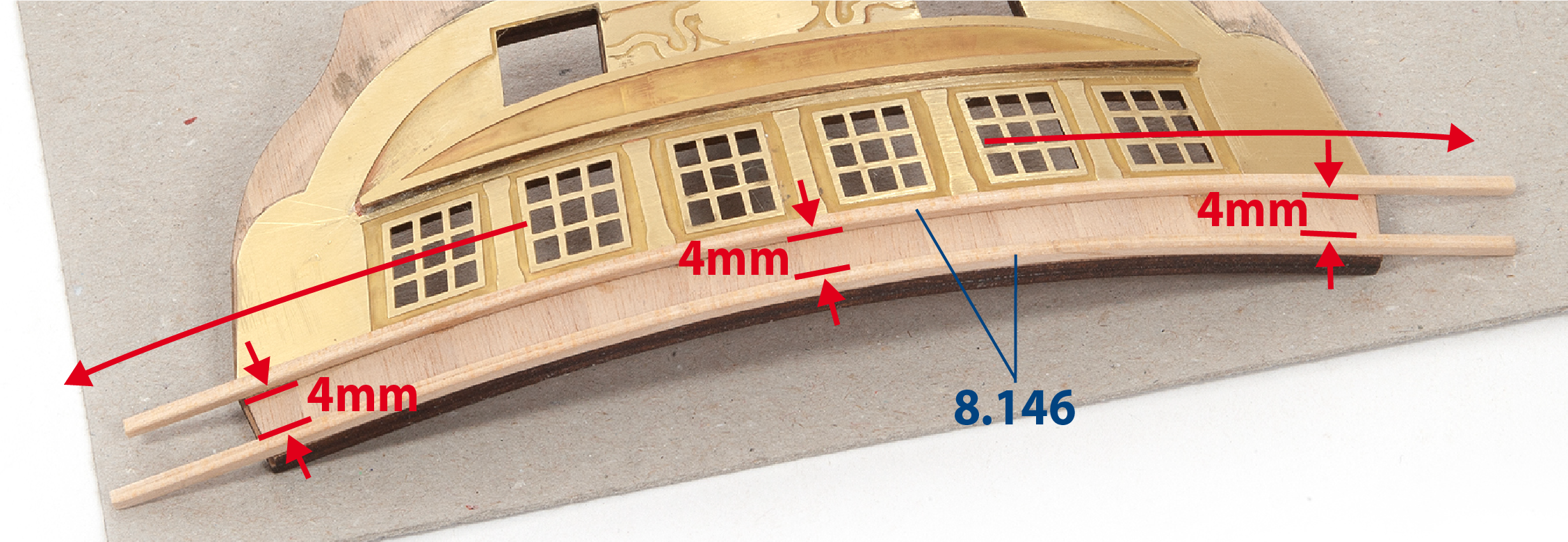
Cut to size part 8.146 (2 x 2 x 160 mm) from the shaped strip, then glue it against the brass part. Glue the second piece leaving a 4 mm gap as shown.
Step 14
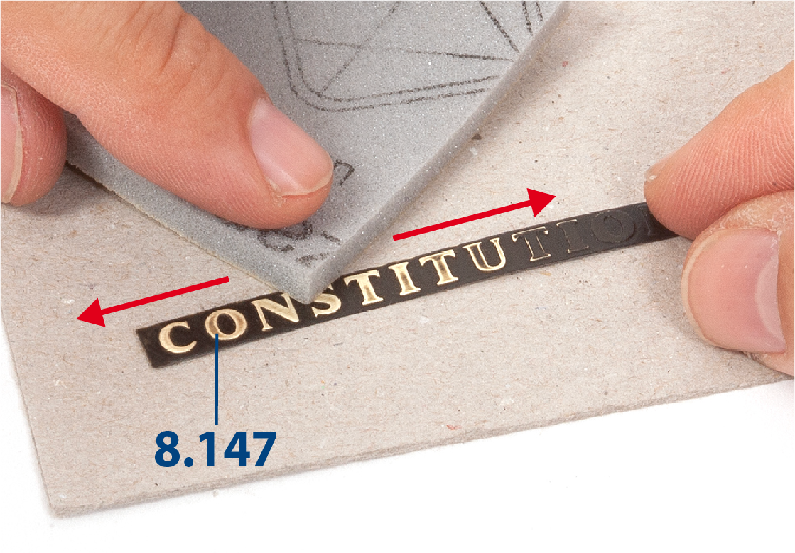
Paint part 8.147 (pack 4) black. When the paint is dry, use a fine sanding sponge to remove the paint from the lettering, keeping it in a flat position. This technique will give you well-defined lettering.
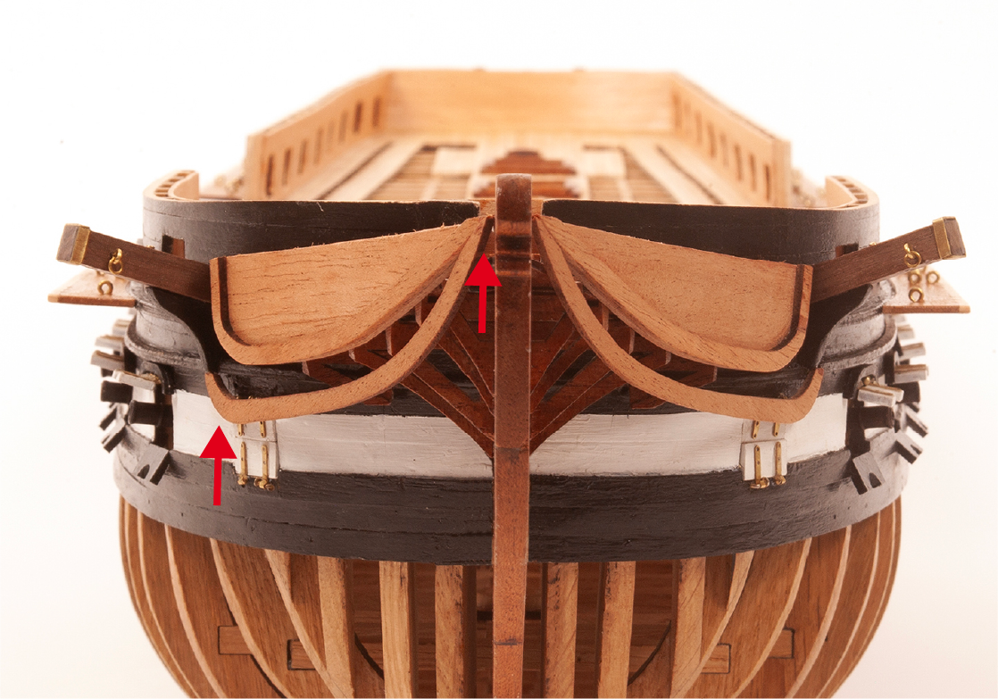
Step 1
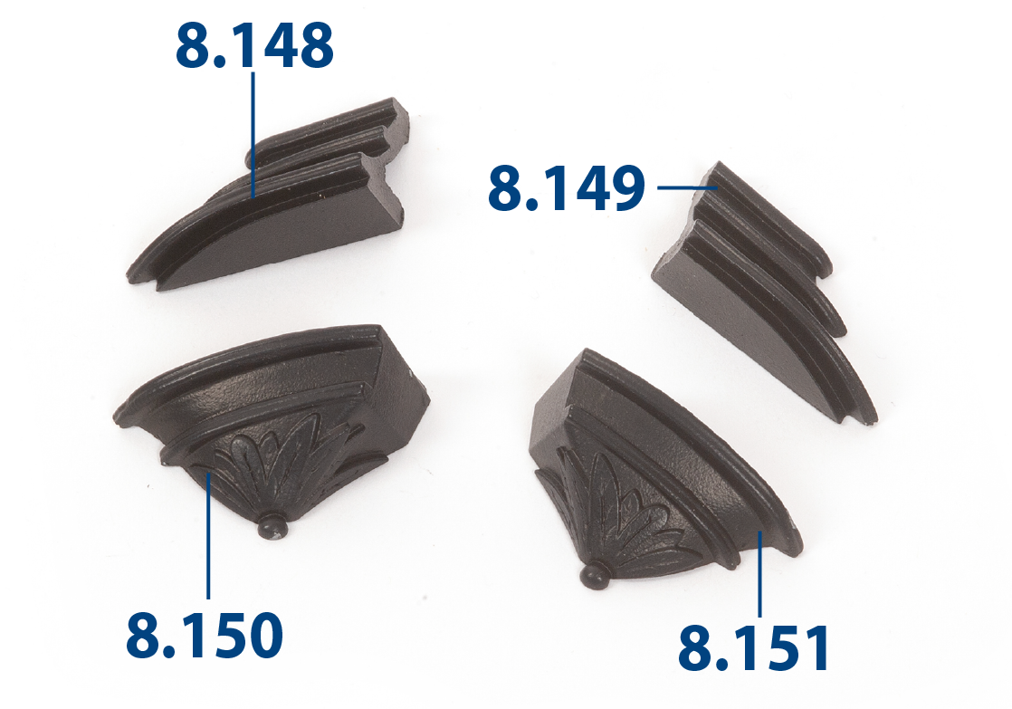
Paint the parts shown in the picture in black. These parts will form the stern gallery.
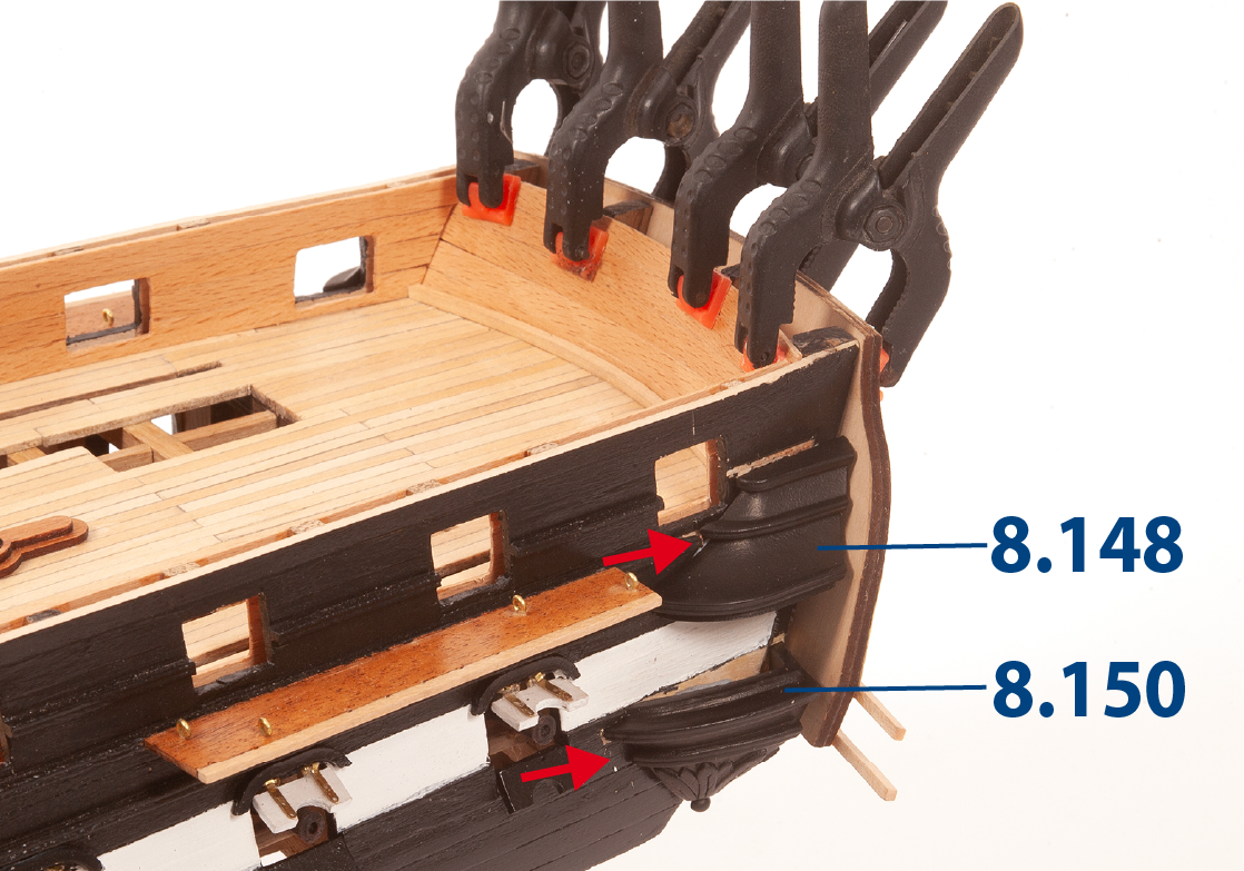
Step 2
Clamp the transom to the hull. Fit the painted parts in place, then mark their position.
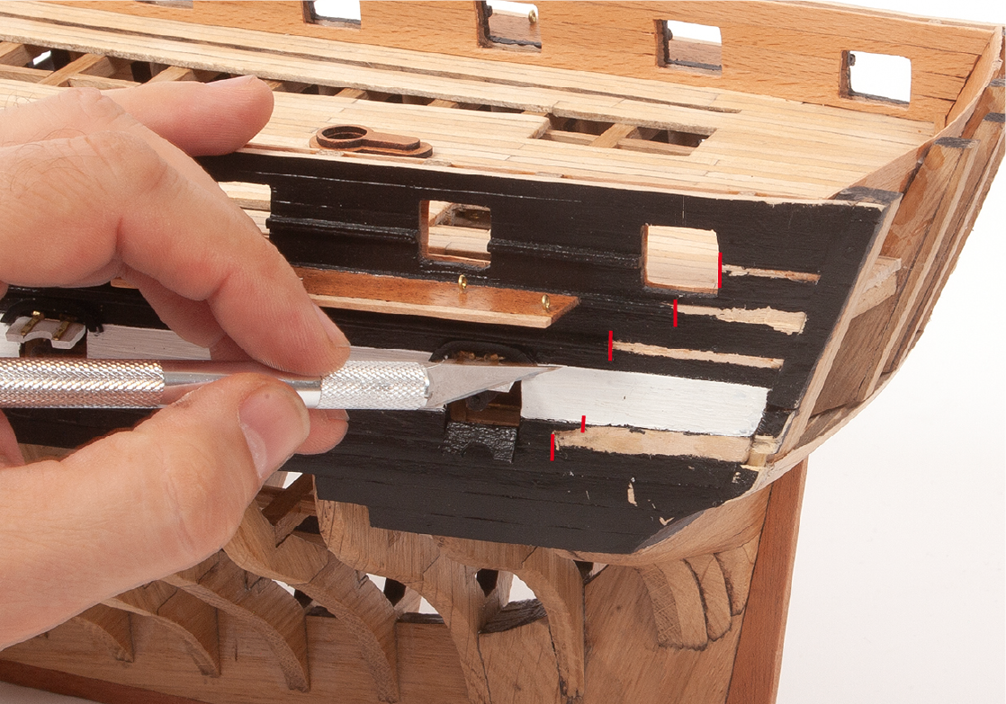
Step 3
Cut and remove any planking that obstructs the painted parts.
Step 4
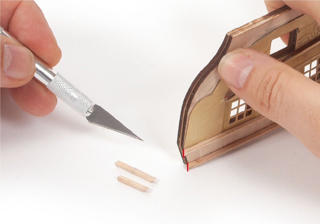
Cut the ends of the shaped strips at an angle, then add smaller pieces to extend the strips around the side.
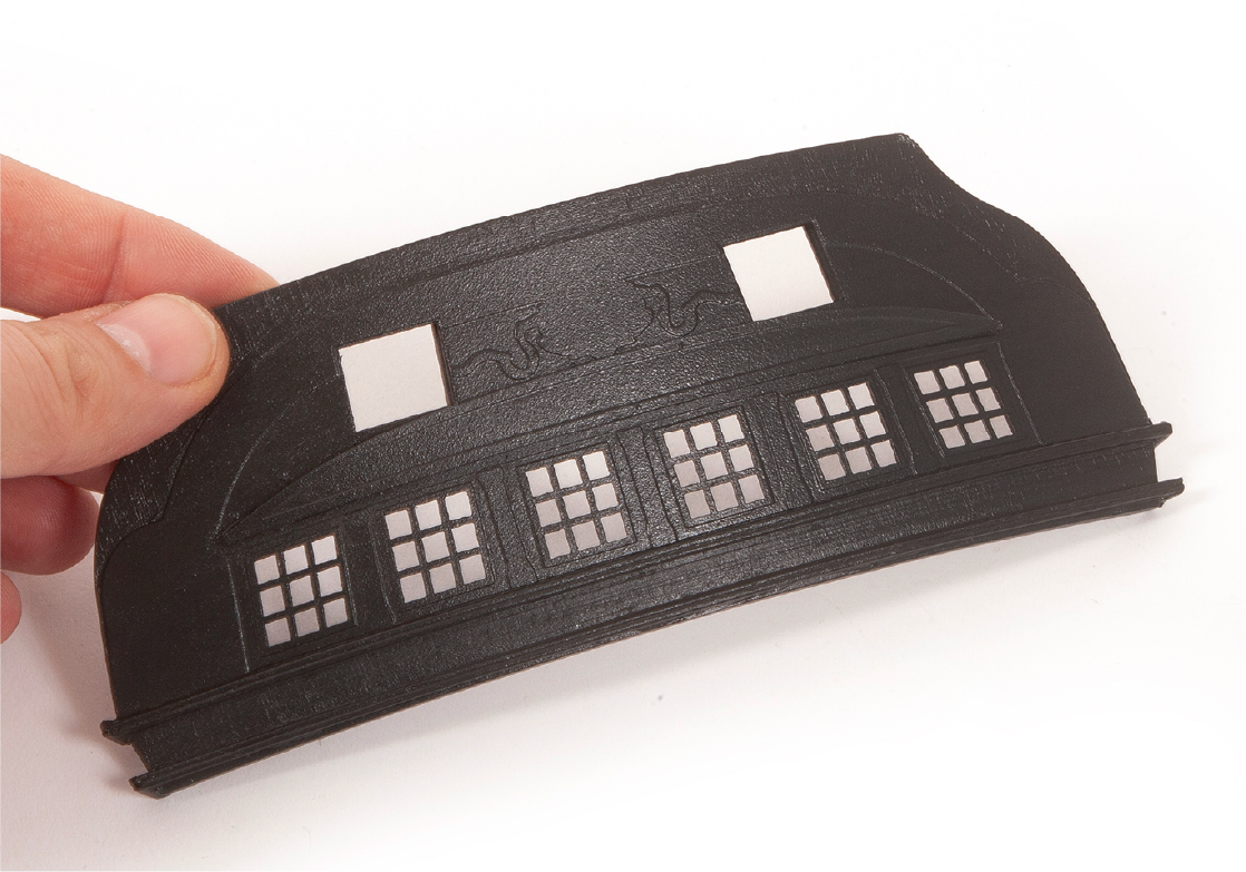
Step 5
Paint the transom black.
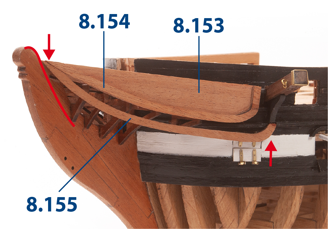
Step 6
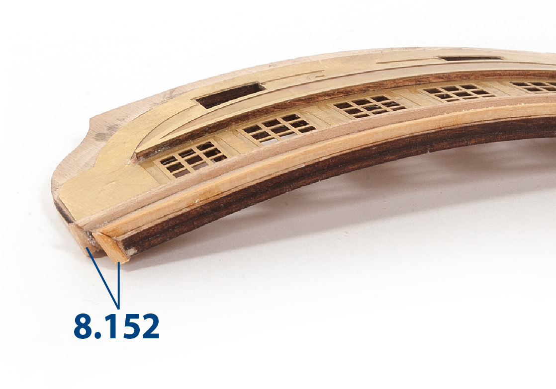
Fit and glue parts 8.153 to 8.155.
Step 7
Proceed in the same way to fit and glue the parts on the other side of the hull.
Step 8
Paint the parts black.
Step 9
Paint the back of the parts black.
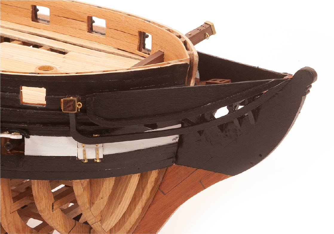
Step 10
This is how the hull should look when this pack is finished.