Pack 02
BUILD INSTRUCTIONS
Instructions for building your Cutty Sark model ship
Your model of the Cutty Sark is divided into 12 packs.
You will need to follow the step-by-step assembly photos, the plans and the explanatory texts below.
Please save the leftover materials from each pack for use when instructed to do so at a later stage of the assembly instructions.
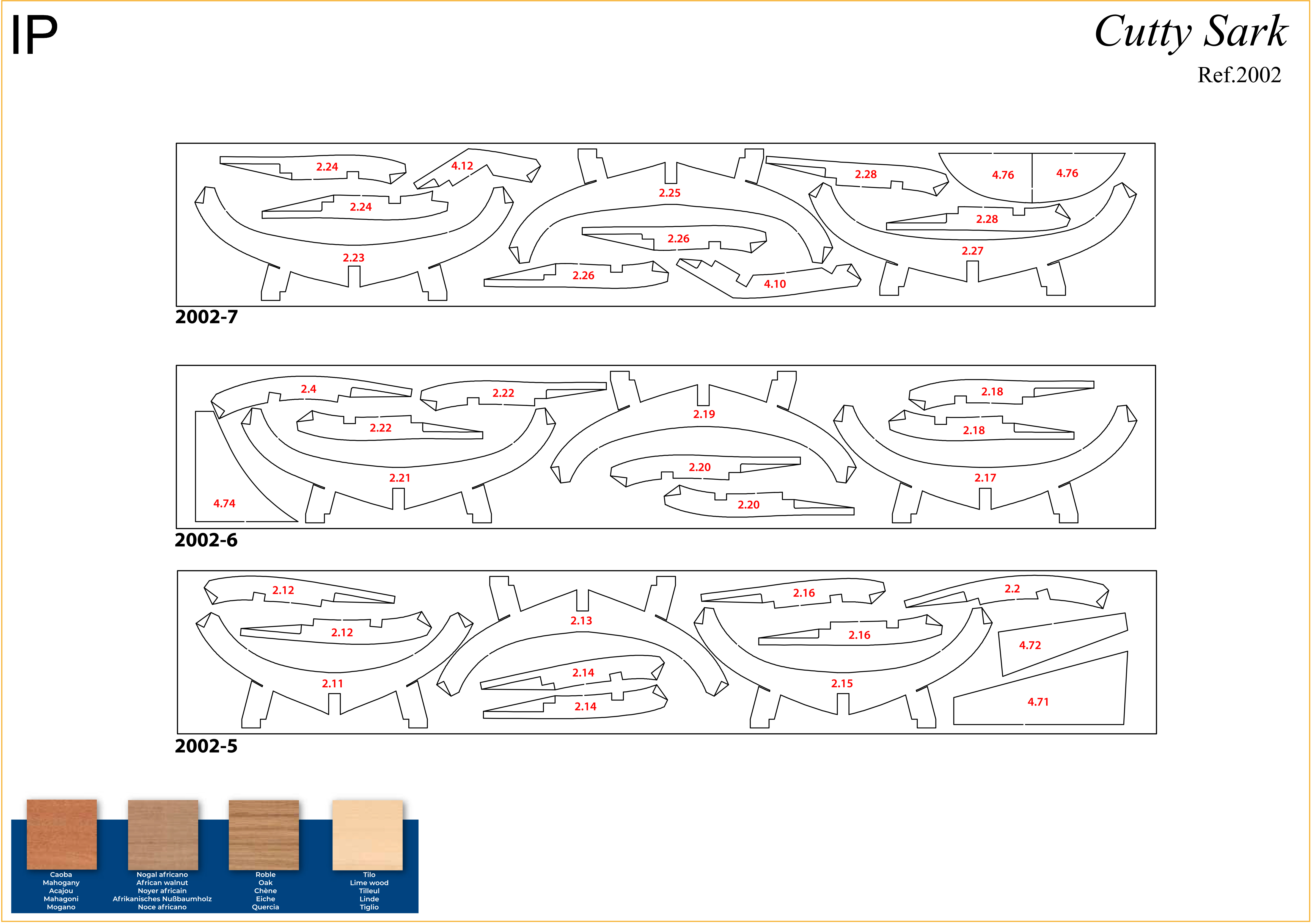
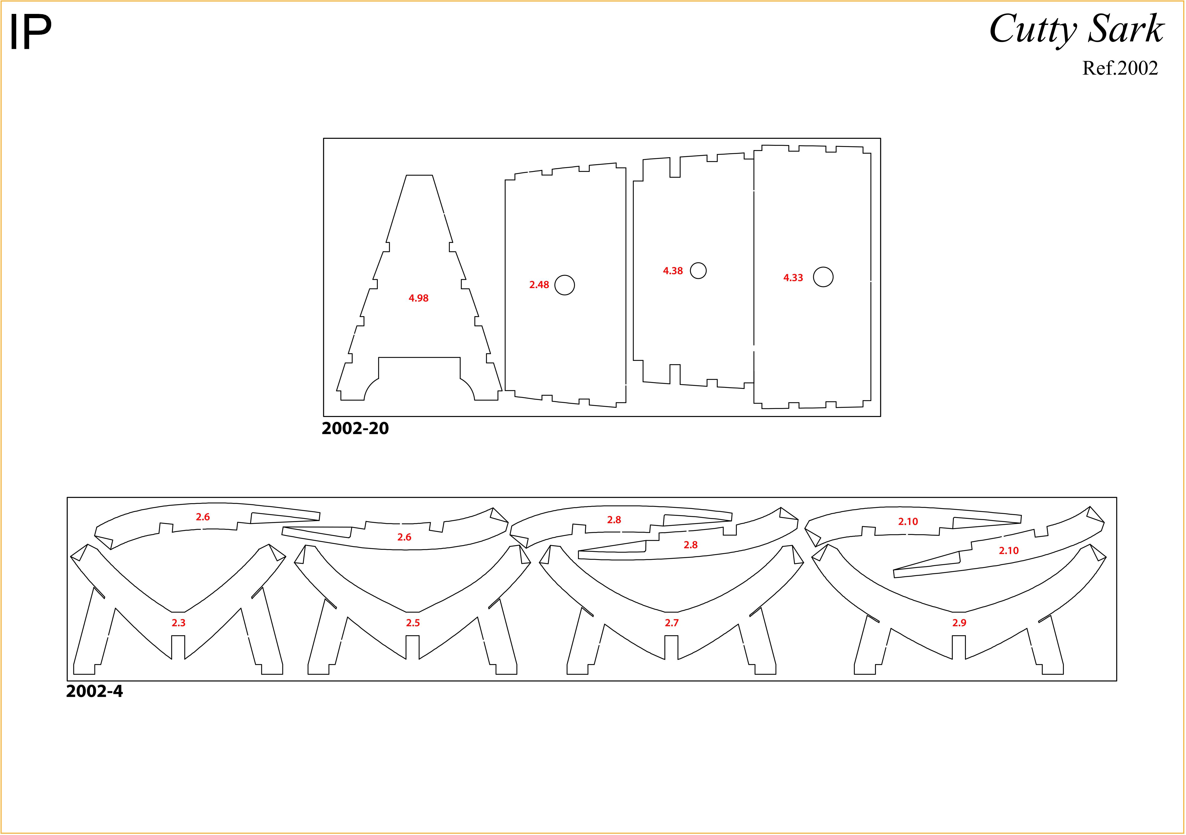
The IP sheets displayed below are drawings of laser-cut parts and photo-etched brass parts and will serve as a guide for identification of some parts.
Use the PARTS REFERENCE table to help locate the parts.
The PL-00 templates (printed at 1/1 scale) will serve as a guide for building the frames.
Please check the list below to ensure you have all the tools required for building your wooden ship.
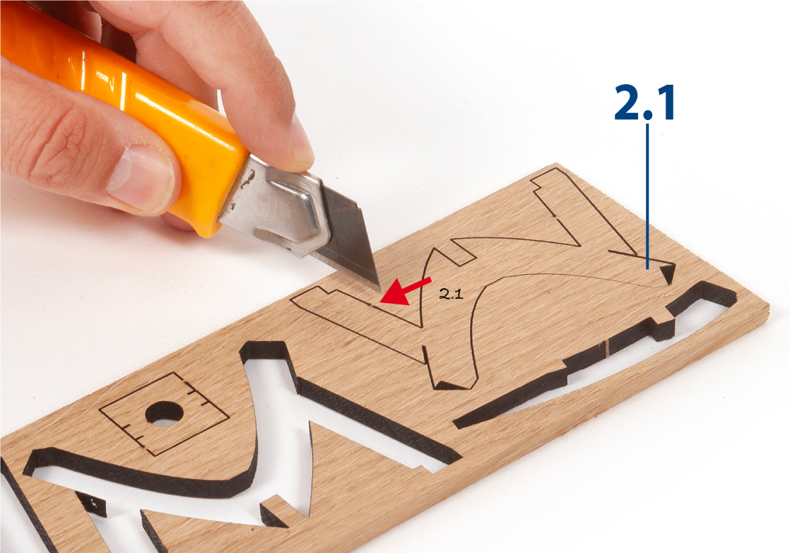
When removing a part, cut the ribs that join the part to the wooden plate with a cutter.
Remove the parts carefully so as not to break them.
Keep and store the parts in their frames. Only remove the parts you are working on in each step.
Extra support can be found on our forum.
PARTS LIST
| Material | Quantity | |
| Wooden Boards | ||
| 2002-4, 2002-5, 2002-6, 2002-7 | Wood | 4 |
| 2002-20 | Wood | 1 |
| Wooden Strips | ||
| 5 x 5 x 400 mm | Oak | 9 |
| 3 x 3 x 400 mm | Lime wood | 6 |
| 2 x 3 x 600 mm | Lime wood | 15 |
| Wooden Rods | ||
| ø10 mm x 450 mm | Mahogany | 1 |
| Templates | ||
| Assembly templates PL-02, PL-03, and PL-04 | 3 |
Useful tools for building this model: cutting mat, pencil, cutting knife, fine-grit sandpaper or sponge sandpaper, file, white wood glue, super glue (cyanoacrylate glue), masking tape, set square, hacksaw, sanding block, 30 cm steel ruler, clamps, moulding scriber tool
PACK 02 - PARTS IDENTIFICATION
PARTS REFERENCE
PART NO. | REFERENCE | PART NO. | REFERENCE | PART NO. | REFERENCE |
| 2.1 | 2002-3 (pack 1) | 2.11 | 2002-5 | 2.21 | 2002-6 |
| 2.2 | 2002-2 (pack 1) / 2002-5 | 2.12 | 2002-5 | 2.22 | 2002-6 |
| 2.3 | 2002-4 | 2.13 | 2002-5 | 2.23 | 2002-7 |
| 2.4 | 2002-2 (pack 1) / 2002-6 | 2.14 | 2002-5 | 2.24 | 2002-7 |
| 2.5 | 2002-4 | 2.15 | 2002-5 | 2.25 | 2002-7 |
| 2.6 | 2002-4 | 2.16 | 2002-5 | 2.26 | 2002-7 |
| 2.7 | 2002-4 | 2.17 | 2002-6 | 2.27 | 2002-7 |
| 2.8 | 2002-4 | 2.18 | 2002-6 | 2.28 | 2002-7 |
| 2.9 | 2002-4 | 2.19 | 2002-6 | 2.29 | 2002-2 (pack 1) |
| 2.10 | 2002-4 | 2.20 | 2002-6 | 2.48 | 2002-20 |
![]()
For extra support and guidance, John Builds Iconic Military Models demonstrates his build of the Cutty Sark on his YouTube channel, sharing 30+ years of wooden ship-building experience. Experts can be found on our Forum.
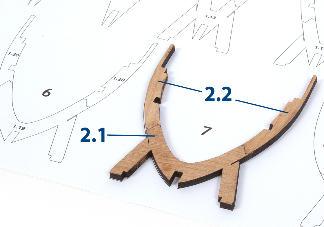
Step 1
Prepare parts 2.1 and 2.2 as follows. Write the numbers using a pencil on the corresponding parts, referring to the IP diagrams above.
Cut out the parts with a craft knife.
Only remove the parts you are working on in each step.
Step 2
Place parts 2.1 and 2.2 on the frame 7 outline on template PL-01 to check the fit.
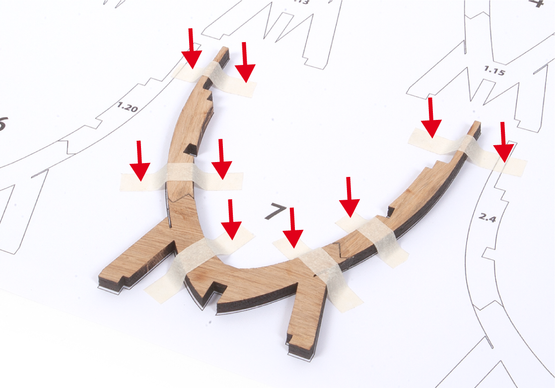
Step 3
Apply glue to the ends of the parts and glue the pieces together to build frame 7. Use pieces of masking tape to immobilise the parts on the template until the glue dries.
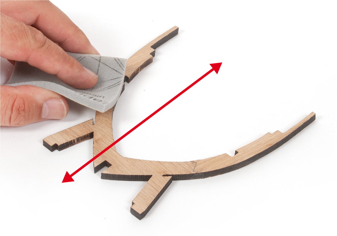
Step 4
Once the glue has dried, sand the frame with a fine-grit sanding sponge to remove any glue or paper residue. Write number 7 in pencil on the frame.
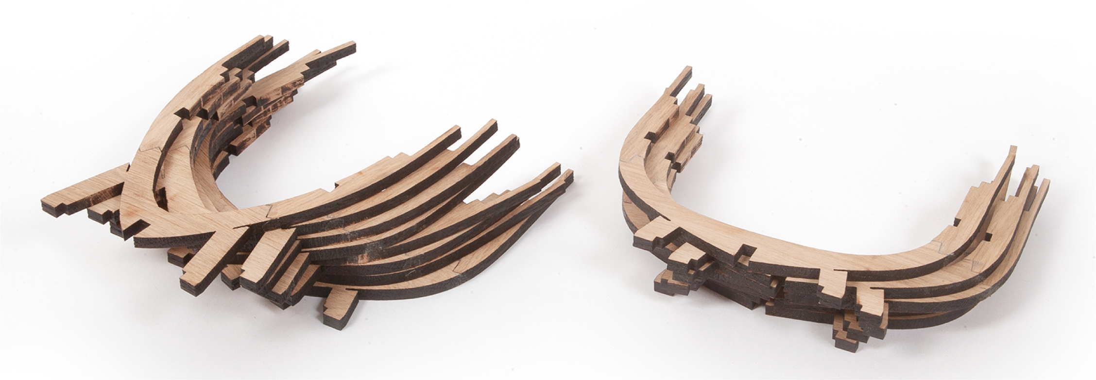
Step 5
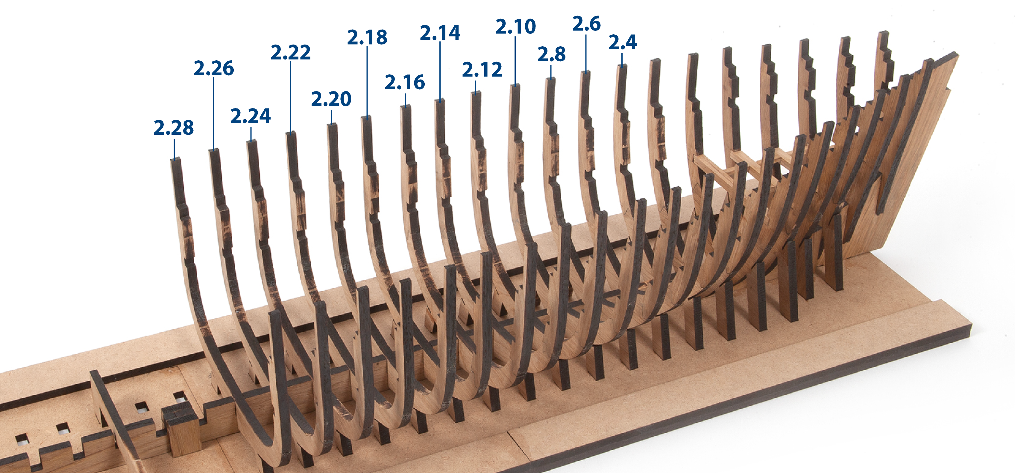
Repeat this procedure to build frames 8–20, using templates PL-01, PL-02, PL-03 and PL-04 as guides. Write the frame numbers (8–20) in pencil on each frame.
Step 6
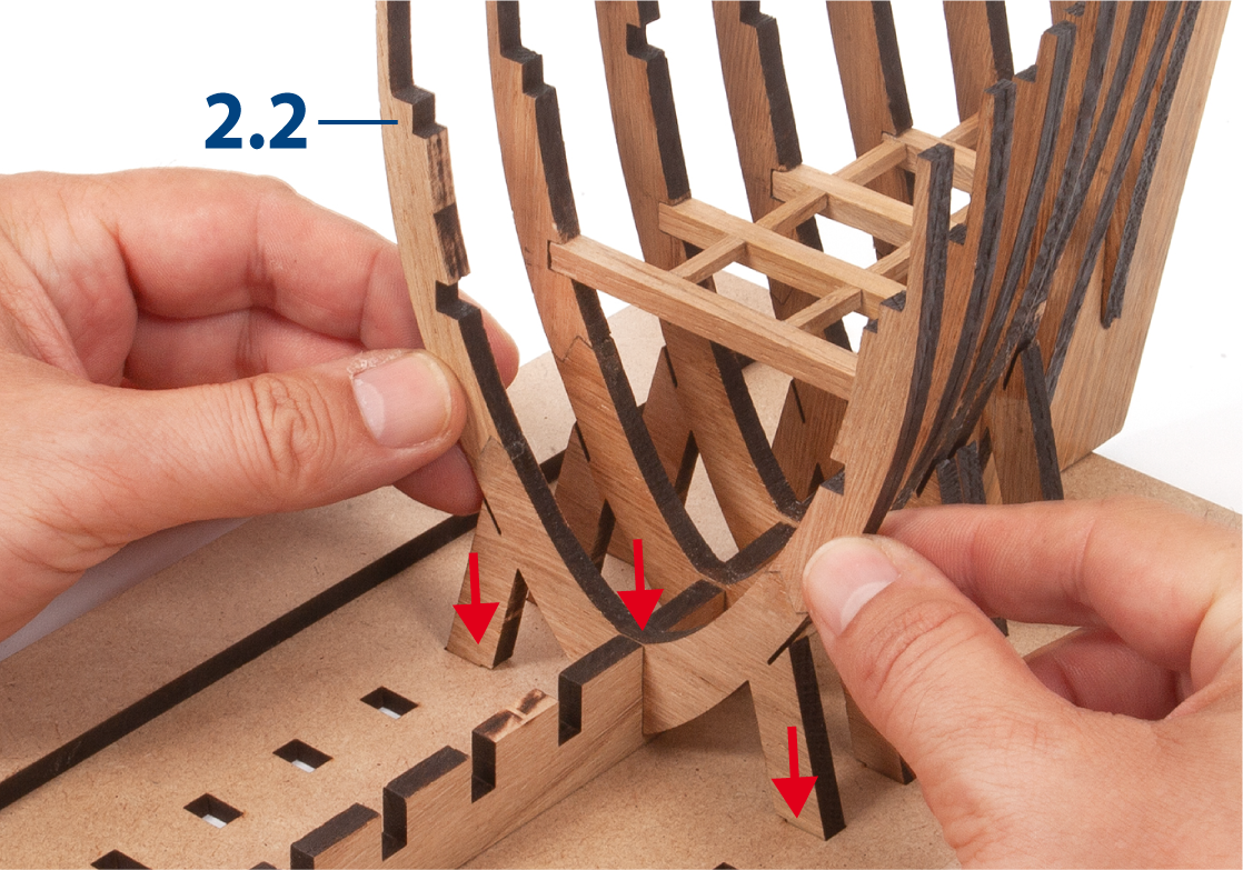
Test-fit frame 7 into the slots in the false keel and the building board.
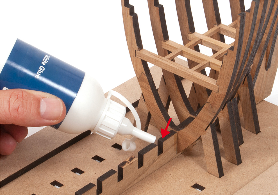
Step 7
Remove the frame. File the slot if necessary, then apply glue to the slot, as shown.
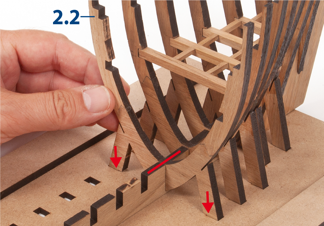
Step 8
Insert and glue frame 7. Make sure the frame sits flush with the false keel, as indicated by the red line.
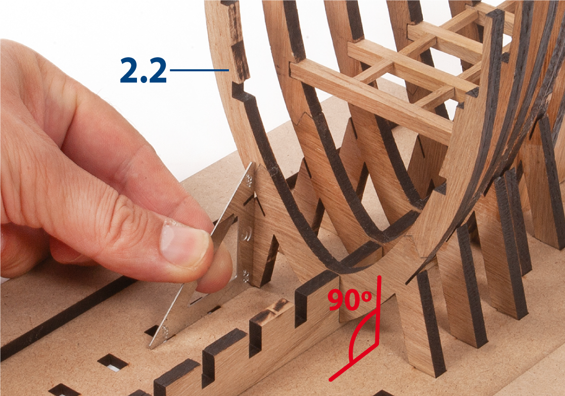
Step 9
Check that the frame is square to the building board using a set square.
Step 10
Repeat the same procedure to glue frames 8–20.
Step 1
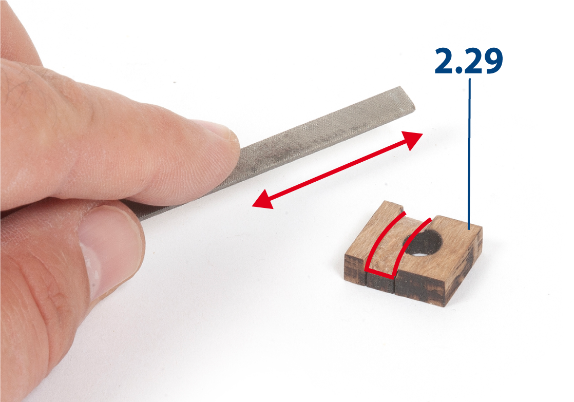
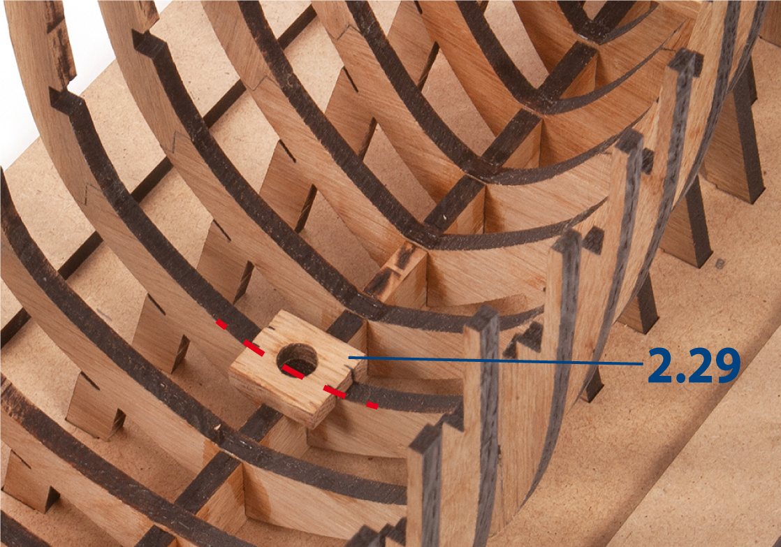
File part 2.29 (from pack 1, ref. 2002-2) so that it fits over frame 10. Then glue the part in place. Make sure the hole is centred over frame 10, as shown in image b.
Step 2
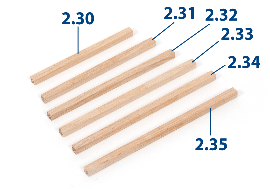
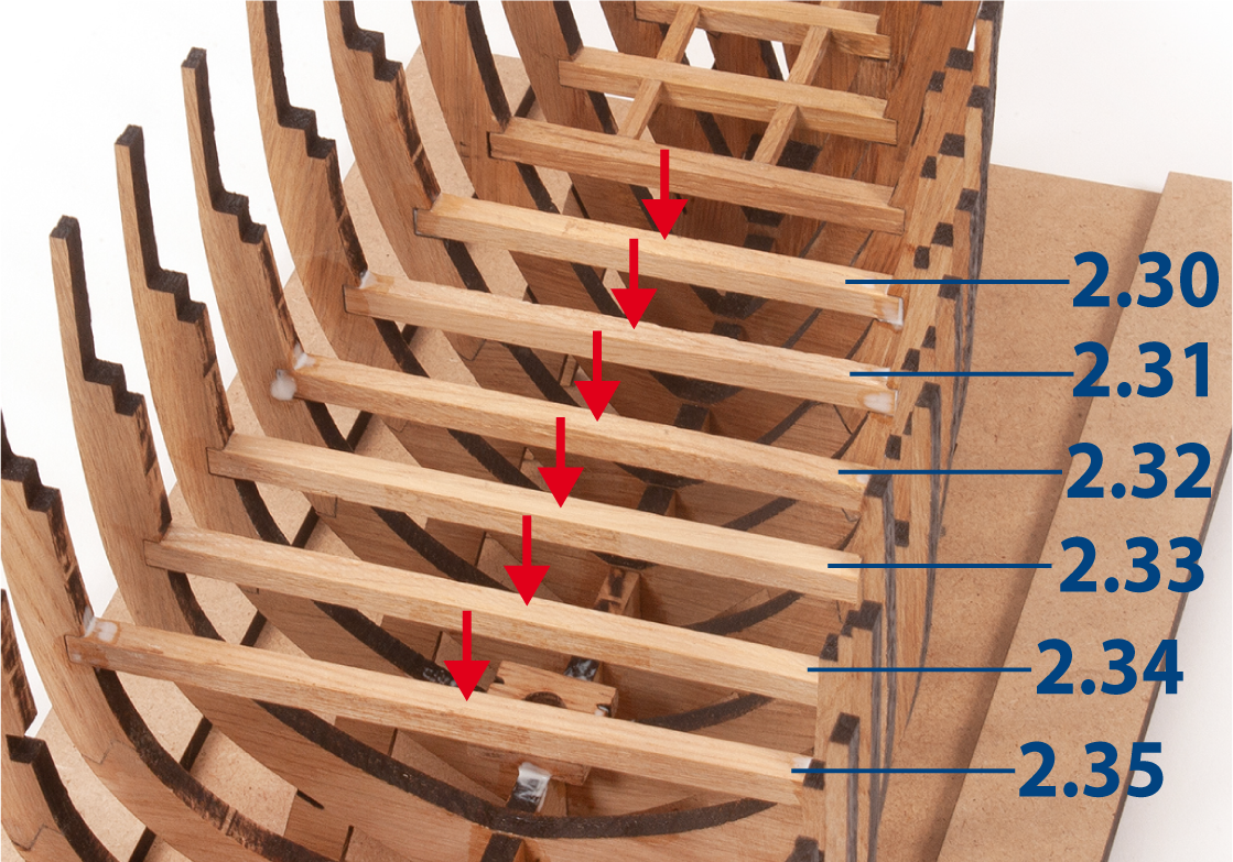
Sand a 5 x 5 mm oak strip with fine-grit sandpaper or a sanding sponge. Then cut parts 2.30 to 2.35 to the lengths shown below.
| 2.30 | 5 x 5 x 81 mm |
| 2.31 | 5 x 5 x 91 mm |
| 2.32 | 5 x 5 x 99 mm |
| 2.33 | 5 x 5 x 106 mm |
| 2.34 | 5 x 5 x 111 mm |
| 2.35 | 5 x 5 x 115 mm |
Step 3
Insert and glue parts 2.30 to 2.35 between the lower recesses, as shown.
Step 4
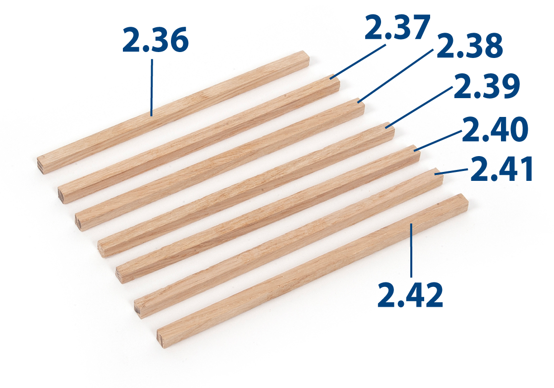
Cut parts 2.36 to 2.42 from a 5 x 5 mm oak strip to the lengths shown below.
| 2.36 | 5 x 5 x 119 mm |
| 2.37 | 5 x 5 x 123 mm |
| 2.38 | 5 x 5 x 126 mm |
| 2.39 | 5 x 5 x 127 mm |
| 2.40 | 5 x 5 x 129 mm |
| 2.41 | 5 x 5 x 130 mm |
| 2.42 | 5 x 5 x 131 mm |
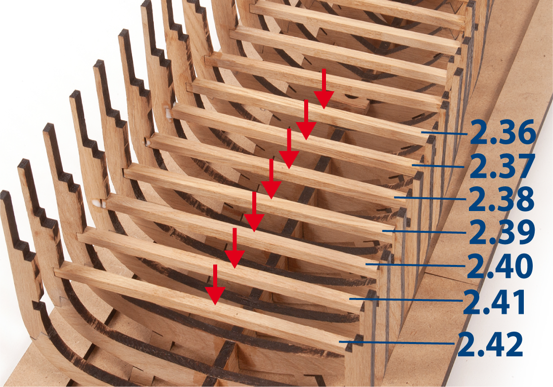
Step 5
Insert and glue the parts between the lower recesses, as shown.
Step 6
Insert parts 1.28 between the frames to keep them parallel. Do not glue.
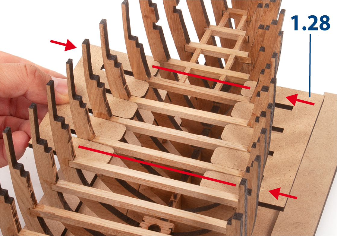
Step 7
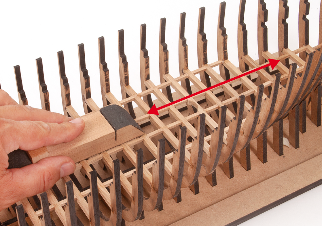
Sand a 3 x 3 mm oak strip with fine-grit sandpaper or a sanding sponge.
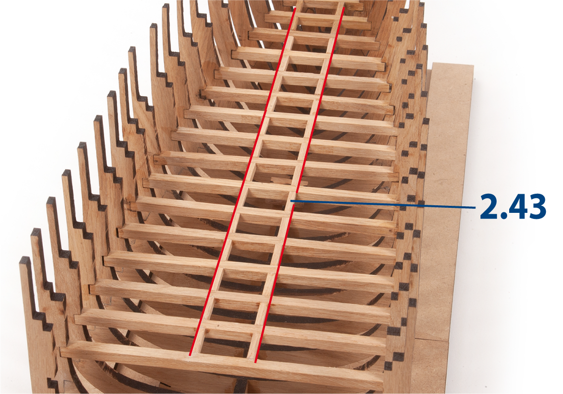
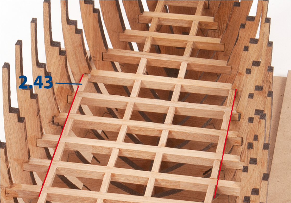
Cut parts 2.43 (3 x 3 x 15 mm) to length and glue them in line with the previous parts up to frame 19. Use a ruler to align the strips, as indicated by the red lines.
Step 8
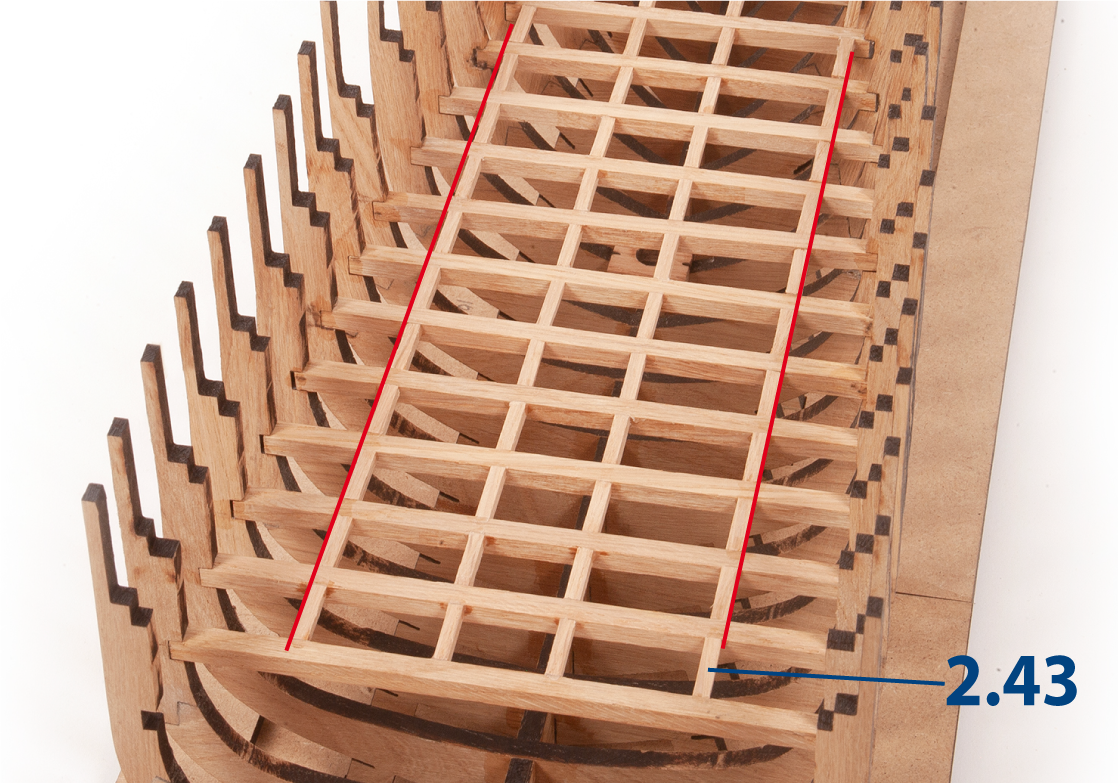
Continue to glue parts 2.43 to form a grid from frame 7–19, as shown. Use a ruler to keep the strips aligned, as indicated by the red lines.
Step 9
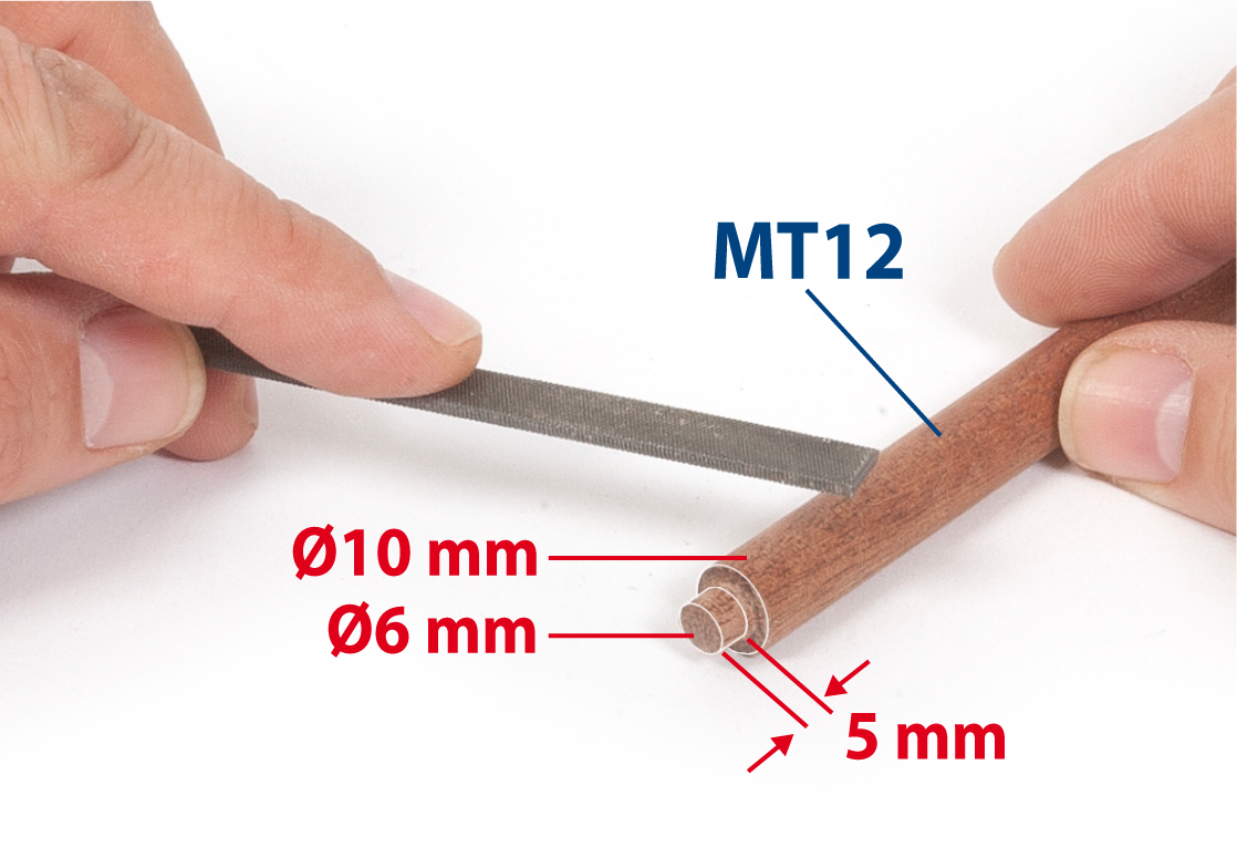
Take a ø10 mm rod and use a flat file to reduce the diameter at one end to the measurements shown to form part MT12.
Step 10
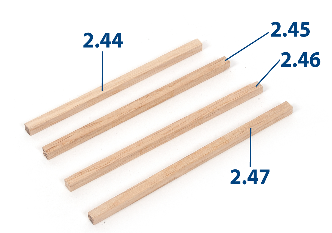
Cut to length parts 2.44 to 2.47 using a 5 x 5 mm oak strip.
| 2.44 | 5 x 5 x 106 mm |
| 2.45 | 5 x 5 x 110 mm |
| 2.46 | 5 x 5 x 114 mm |
| 2.47 | 5 x 5 x 119 mm |
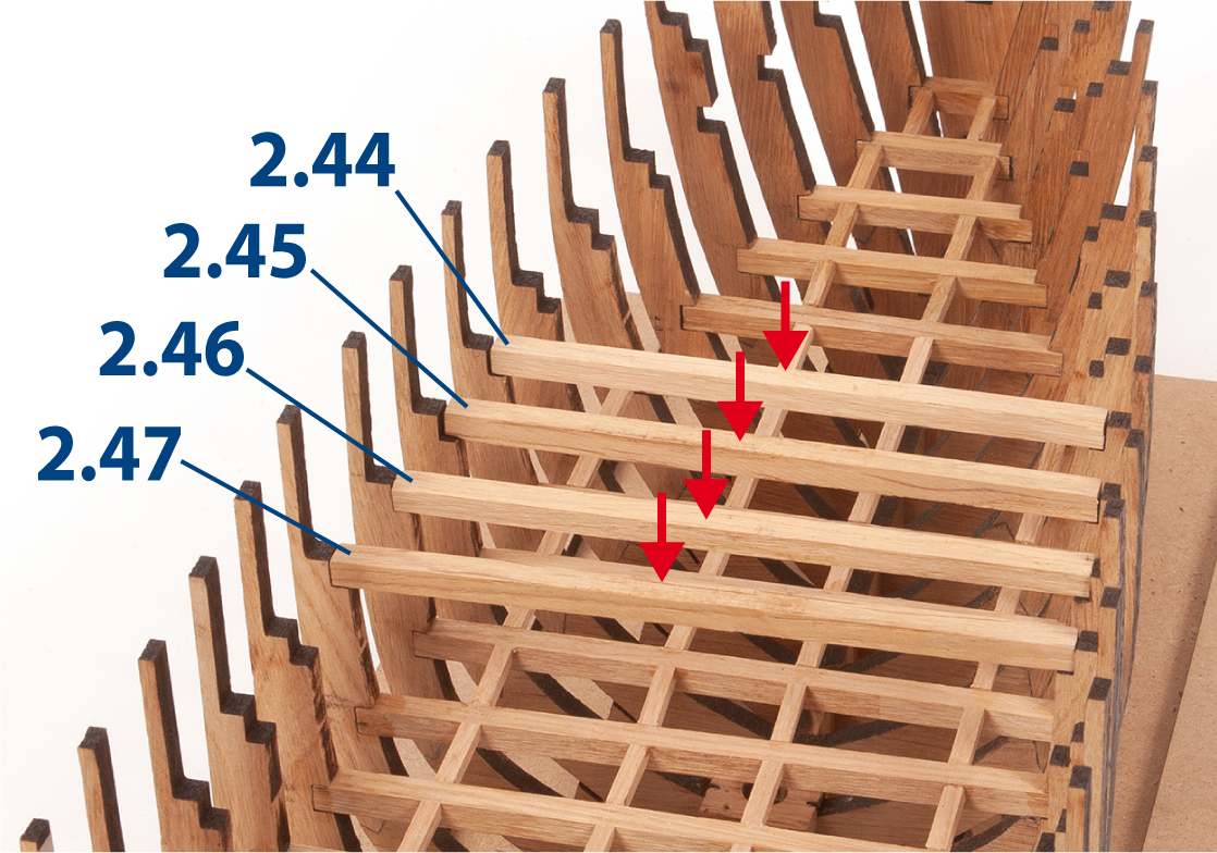
Step 11
Fit the pieces between the upper recesses of frames 9–12. Do not glue.
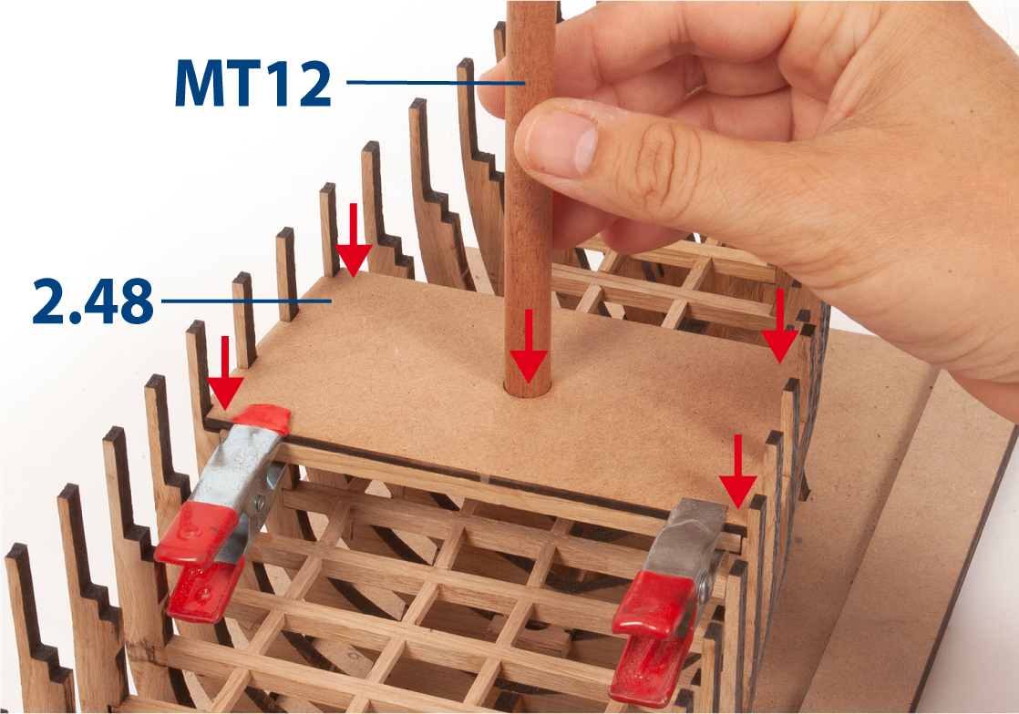
Step 12
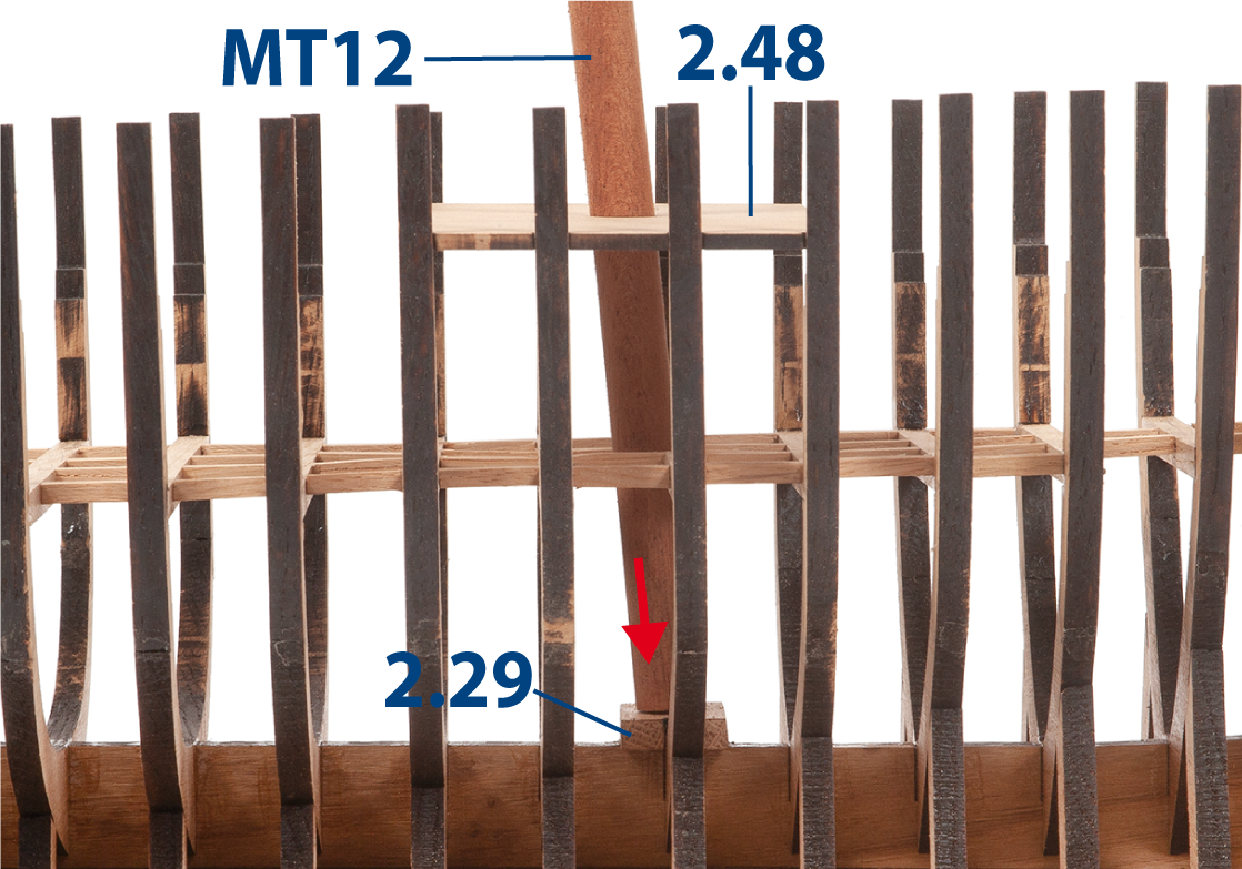
Position part 2.48 between the frames and on the battens. Do not glue. Insert the part carefully to avoid breaking the frames.
Insert part MT12 to check its fit between the battens below and into part 2.29.
Step 13
If part MT12 doesn't fit properly (see step 14), remove the parts and battens, then adjust the opening with a round file.
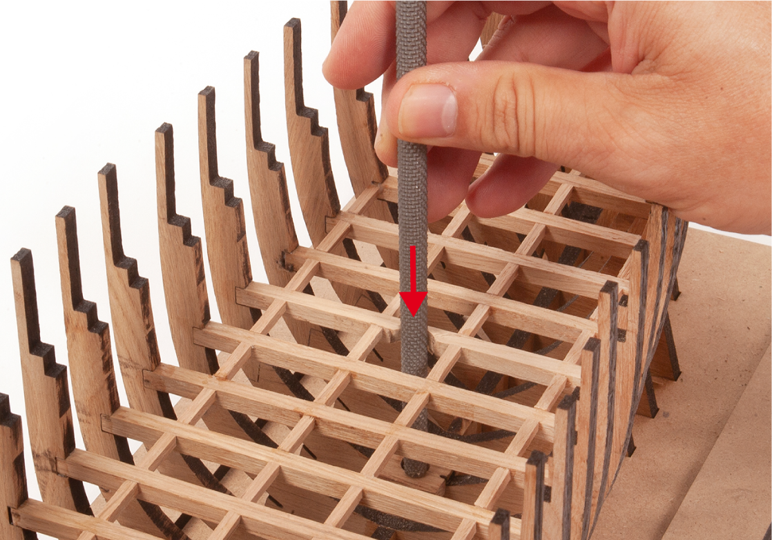
Step 14
This image shows the alignment of the parts. Once part MT12 fits correctly in place, remove parts MT12 and 2.48, then set them aside.
Step 1
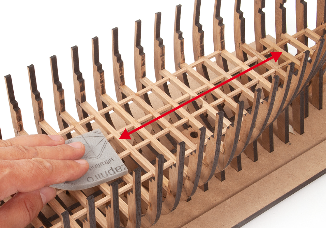
Sand the battens with a sanding block to level any unevenness.
Step 2
Then smooth the battens with a fine-grit sanding sponge.
Step 3
Apply varnish to all the wooden parts you have added to the structure.
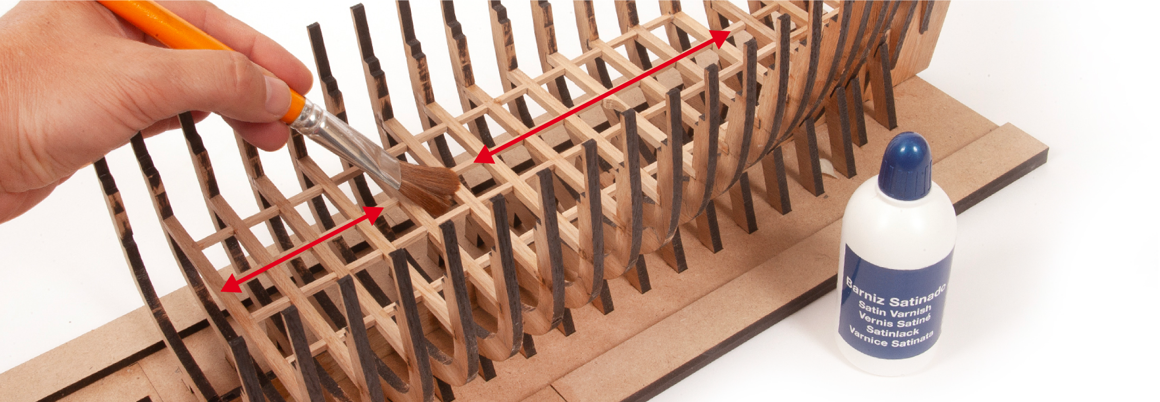
Step 4
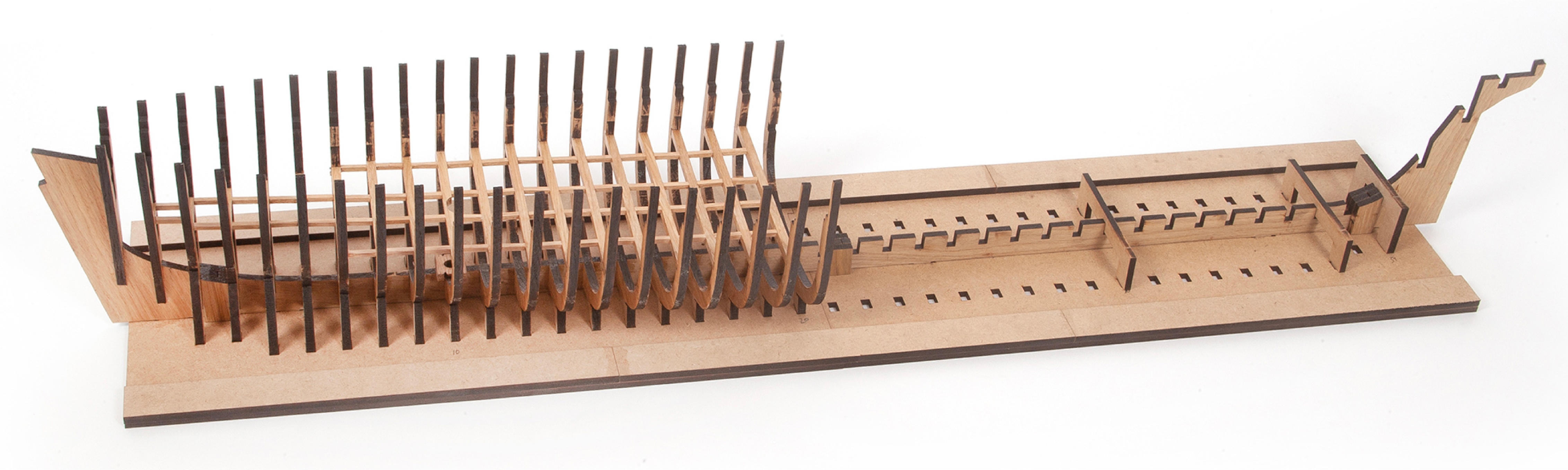
This image shows the assembly at the end of this stage. It is important to keep the structure on the building board at all times.