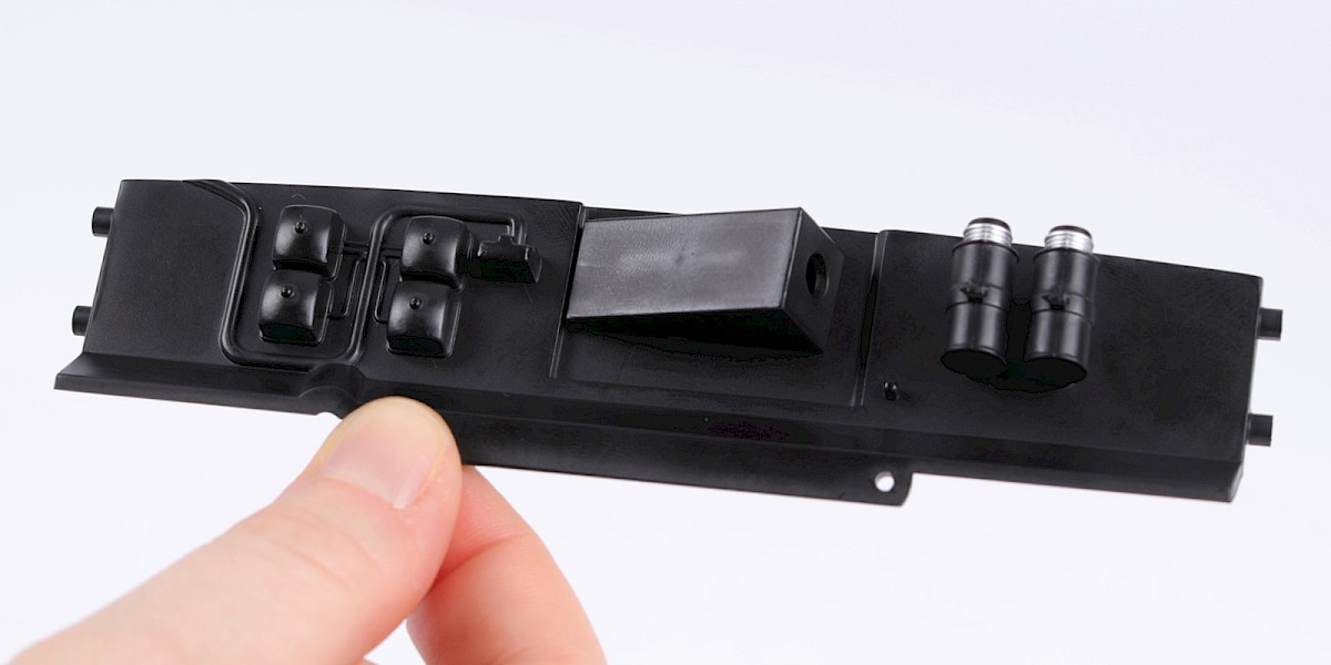
Pack 08
BUILD INSTRUCTIONS
Advice from the experts
Spare screws are included with each part. Occasionally, you may be instructed to keep spare or unused screws for a later stage. Keep these spares in a safe place and label them correctly.
Please make sure you don’t mix up the screws. They look quite similar, but the threads do vary slightly. Using the wrong screws may damage the parts. Only use the correct size screwdriver that fits the screw head firmly.
When securing parts together using multiple screws, fit each screw loosely to ensure all the parts are correctly aligned before gently tightening them firmly, but not overtight, in the order in which you placed them.
The screwdriver can be magnetized by stroking it with a magnet (fridge magnet, etc.) enabling it to hold the screws and make assembly easier.
If a screw is tight going into a metal part, do not force it as you may shear the head off. Remove it and put a tiny smear of Vaseline, soap or light oil on the thread. That will lubricate it and make it easier to tighten.
Some parts will require a little glue for assembly. Please apply glue sparingly and use a cocktail stick so that you don’t use too much nor apply the glue too heavily. We recommend superglue gel or Extra Thin Liquid modeling glue. Where possible, parts should be test-fitted in place before gluing.
Make sure you have good ventilation when using adhesives and to replace caps firmly.
Use a magnet to help find screws that have fallen on the floor.
Use masking tape to hold parts temporarily in place.
Cut parts from a sprue (framework) with side cutters or a craft knife. Side cutters tend to be easiest.
During the course of this build, you will receive many pieces that you will assemble immediately – following the instructions in the corresponding stage – and other pieces that you should store safely to one side, for use in future assembly stages.
Always protect the paint finish on components by placing a cutting mat, sheet of white paper or soft cloth on your work surface.
When plugging cables in, ensure the power is switched off. Tweezers can be used to fit the PVC cables by gripping carefully around 5mm from the end of the cable. If a cable needs to be removed from a socket, do not pull on the cable as this could damage the connection. Grip the plug with tweezers to remove it.
Left and Right! When building your Goldfinger DB5, the left- or right-hand side refers to that side as if you are sitting in the car.
![]() When you see this symbol, pay attention to the instruction text in bold and check the orientation of the parts in the image as this will be particularly important for assembly in later stages.
When you see this symbol, pay attention to the instruction text in bold and check the orientation of the parts in the image as this will be particularly important for assembly in later stages.
WARNING: Some parts are assembled using magnets. These magnets can cause serious injury if they are swallowed. Keep away from children. If you suspect a magnet has been swallowed, seek medical help straight away.
This is not a toy. Not suitable for children under 14 years old due to small parts. Adult supervision required.

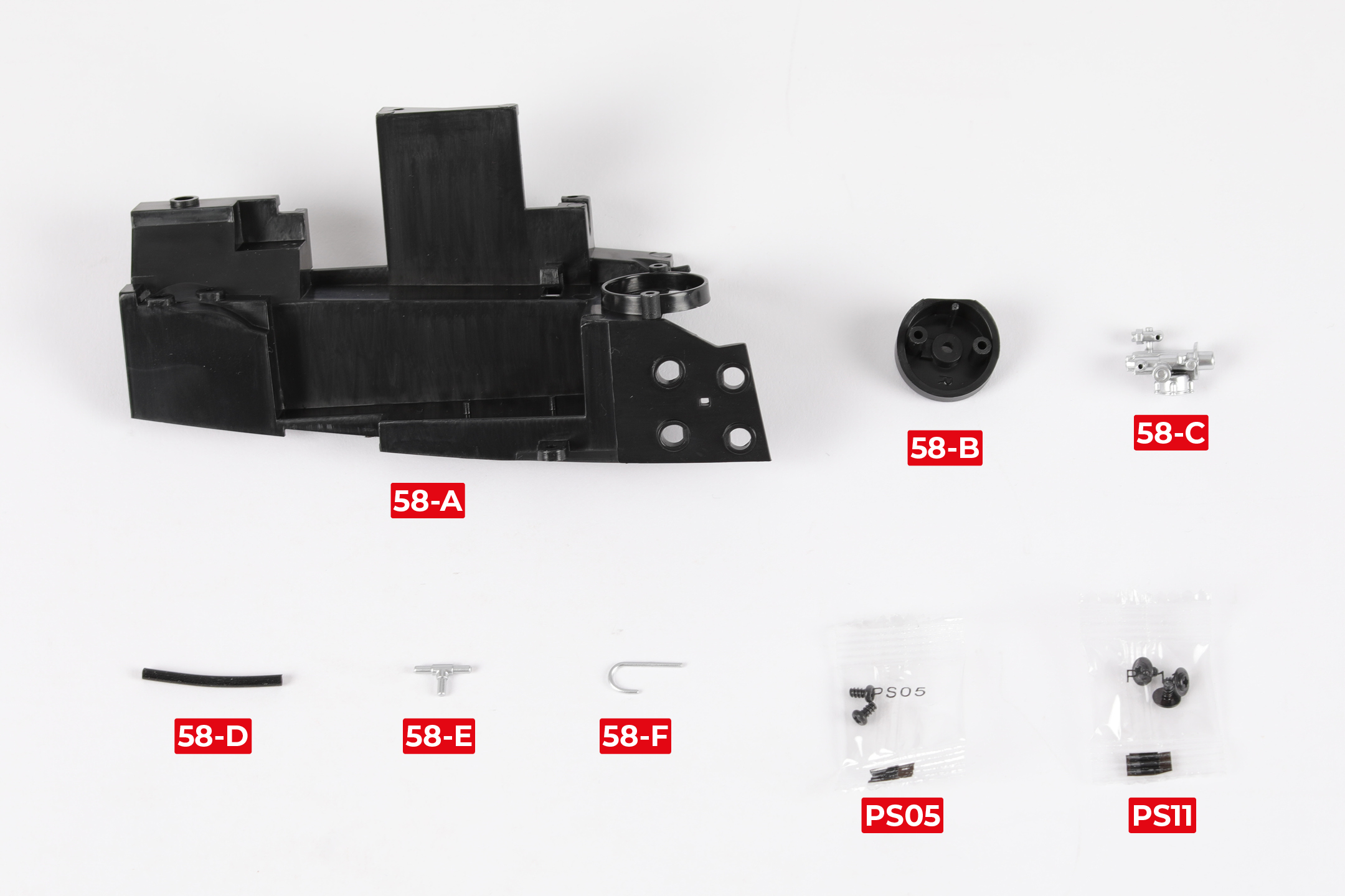
PARTS LIST
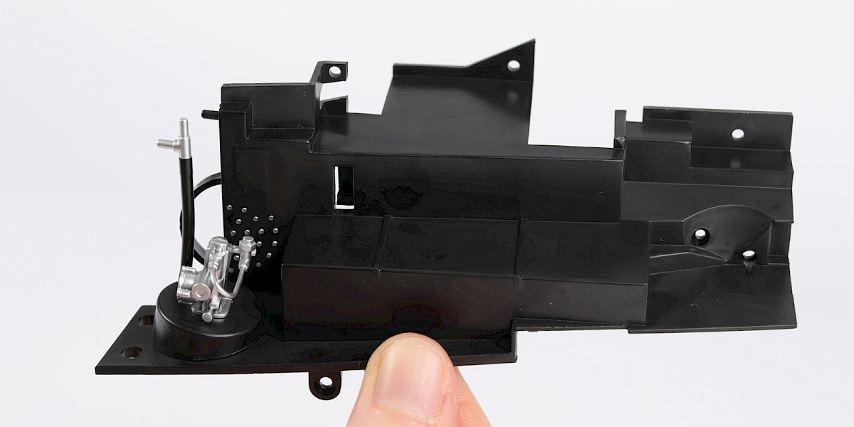
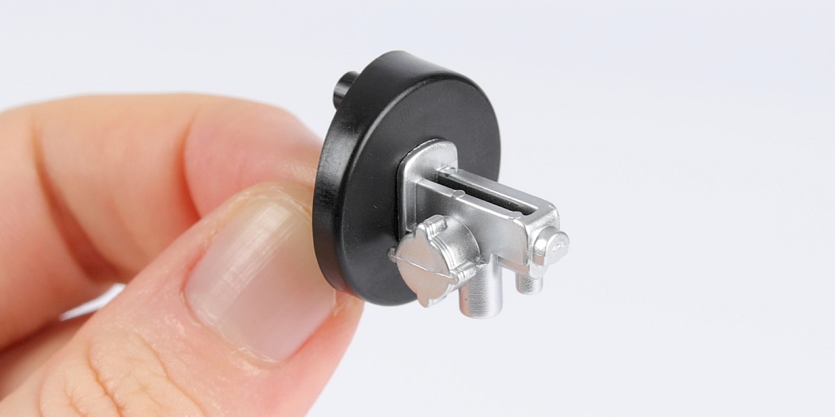
| 58-A Engine bay wall (right) | 58-E T-connector |
| 58-B Brake servo mount | 58-F J-connector |
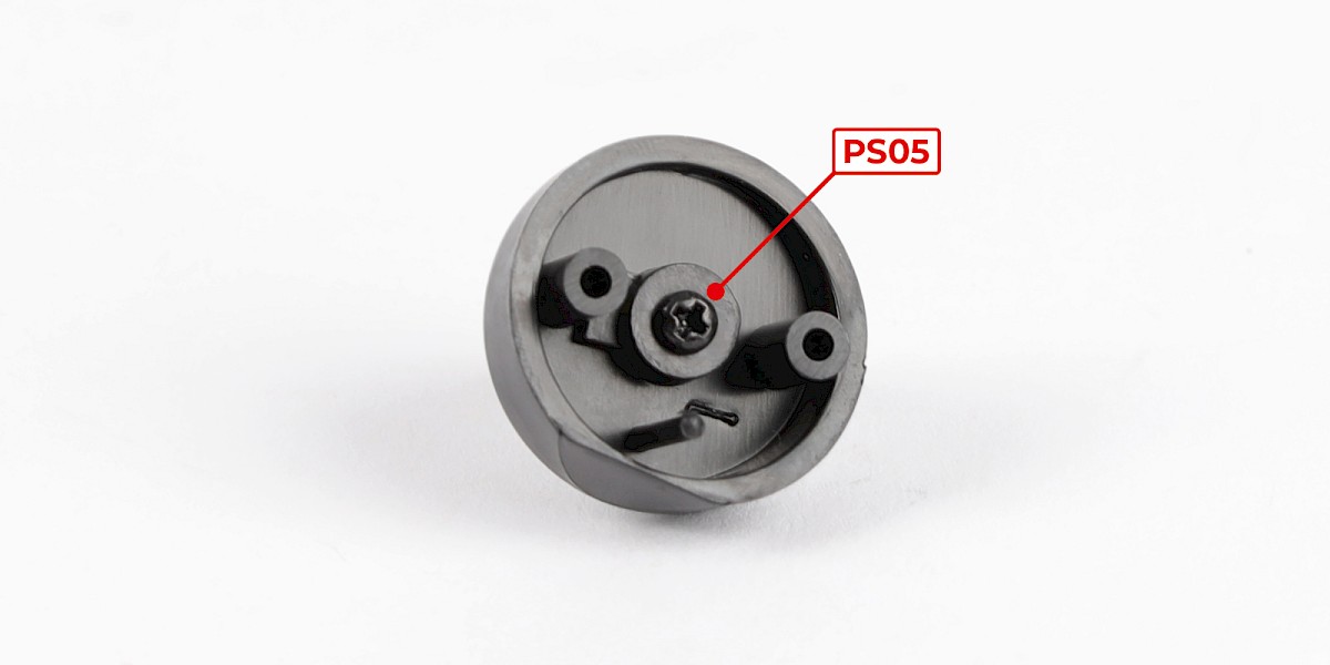
| 58-C Brake servo | 2x PS05 screws |
| 58-D Hose | 3x PS11 screws |
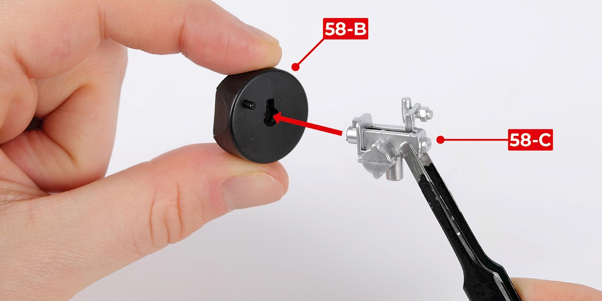
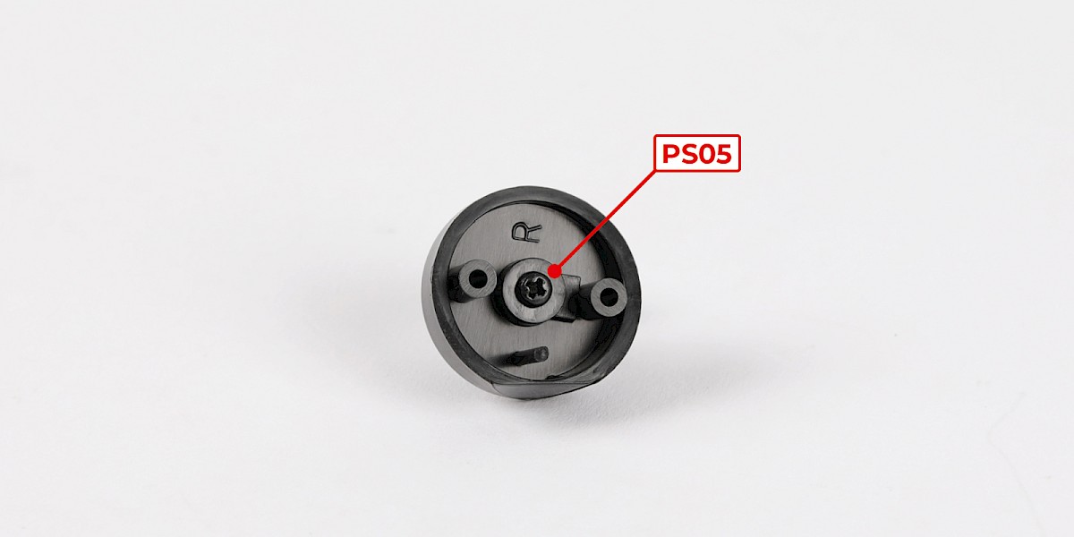
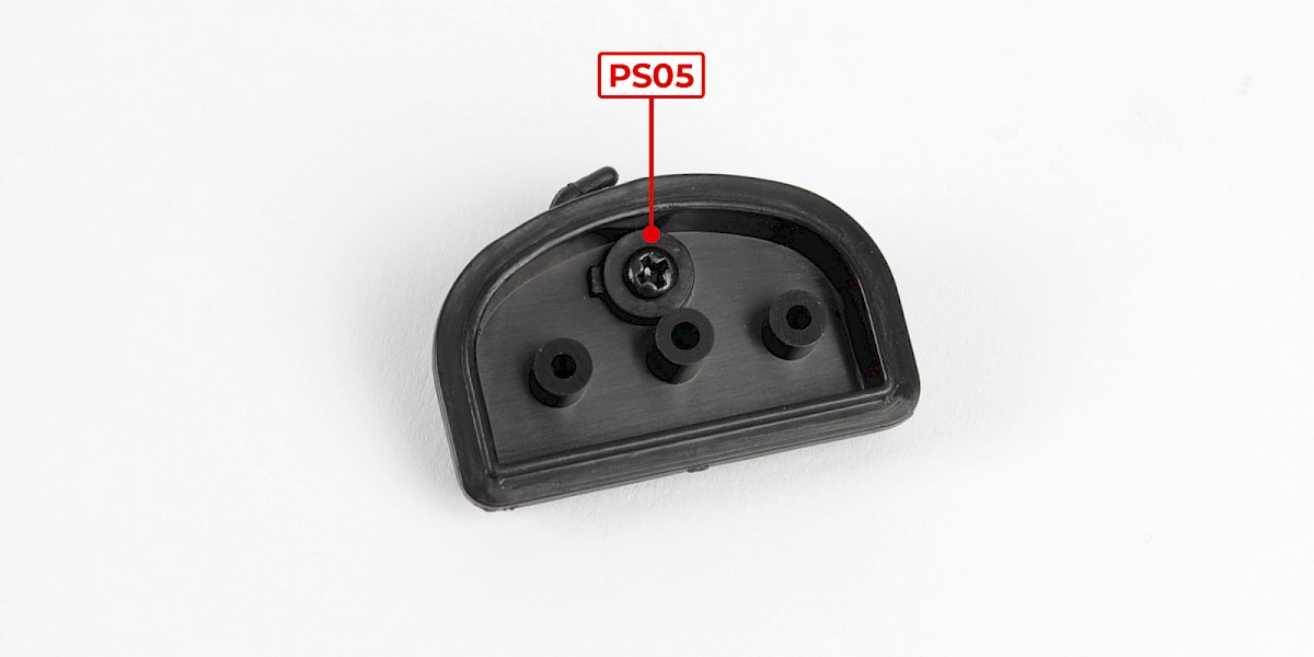
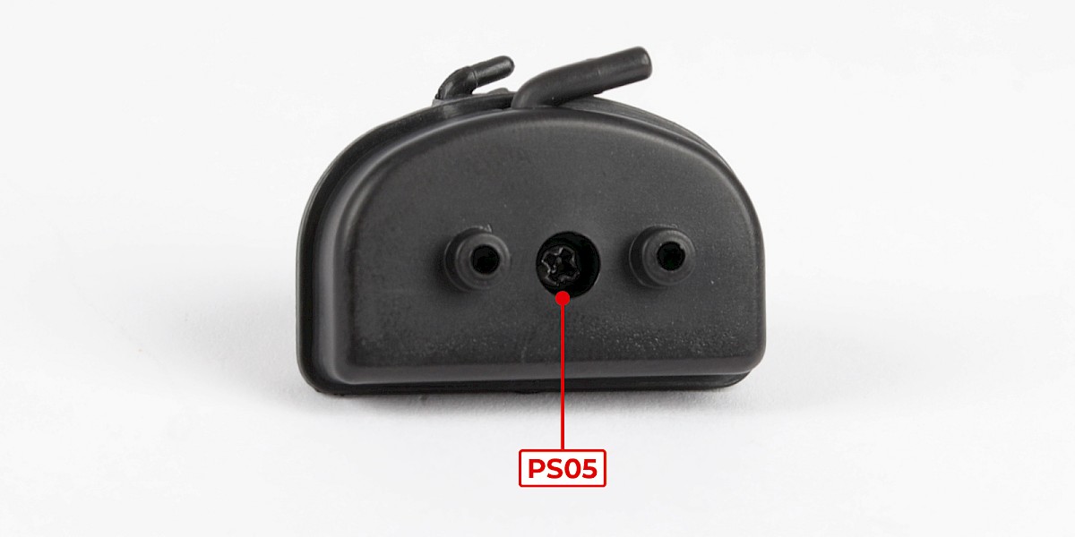
Step 1
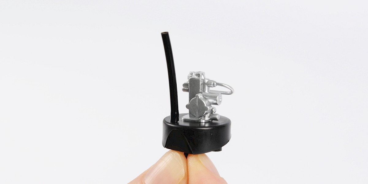
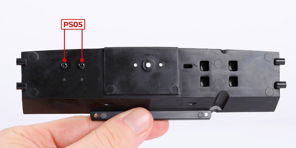
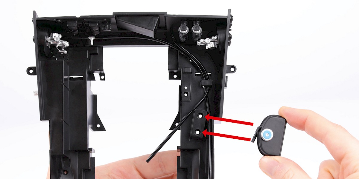
Fit the brake servo (58-C) to the brake servo mount (58-B).
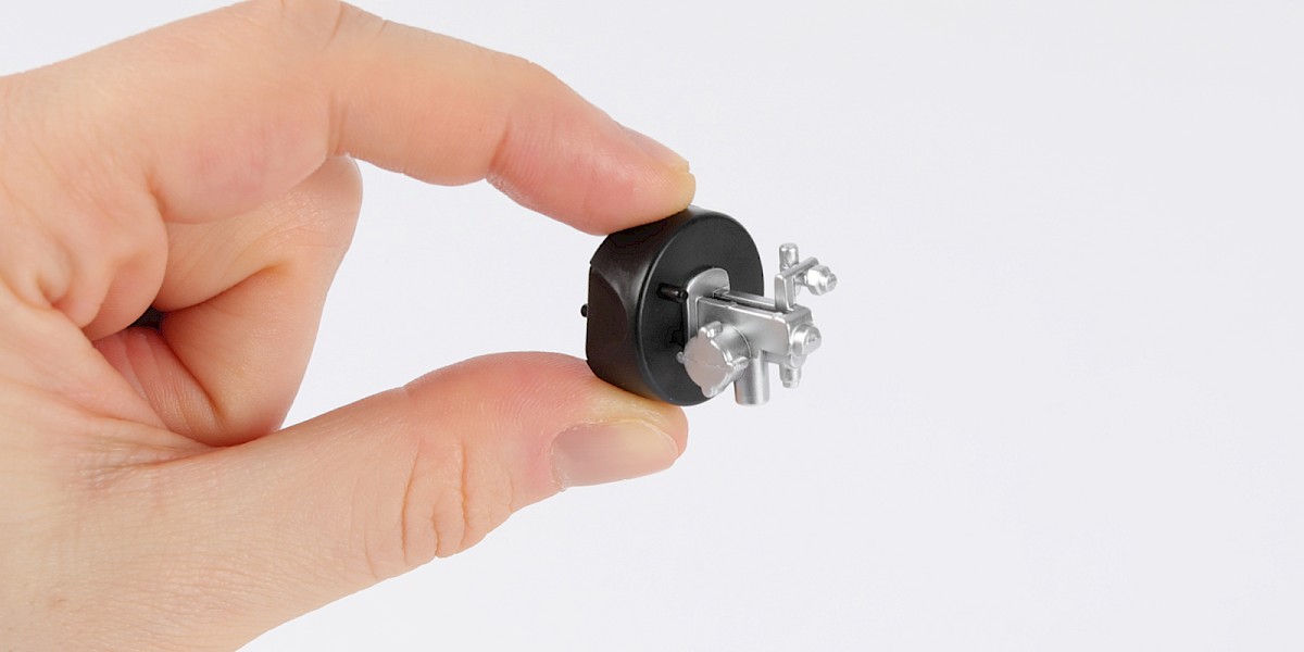
Step 2
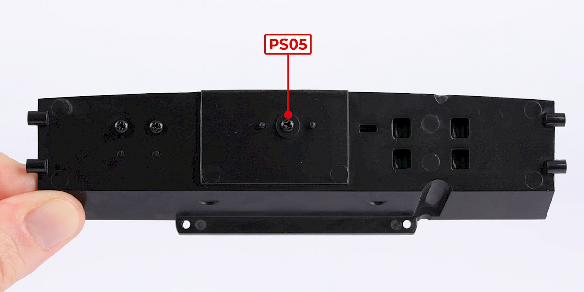
Secure with 1x PS05.
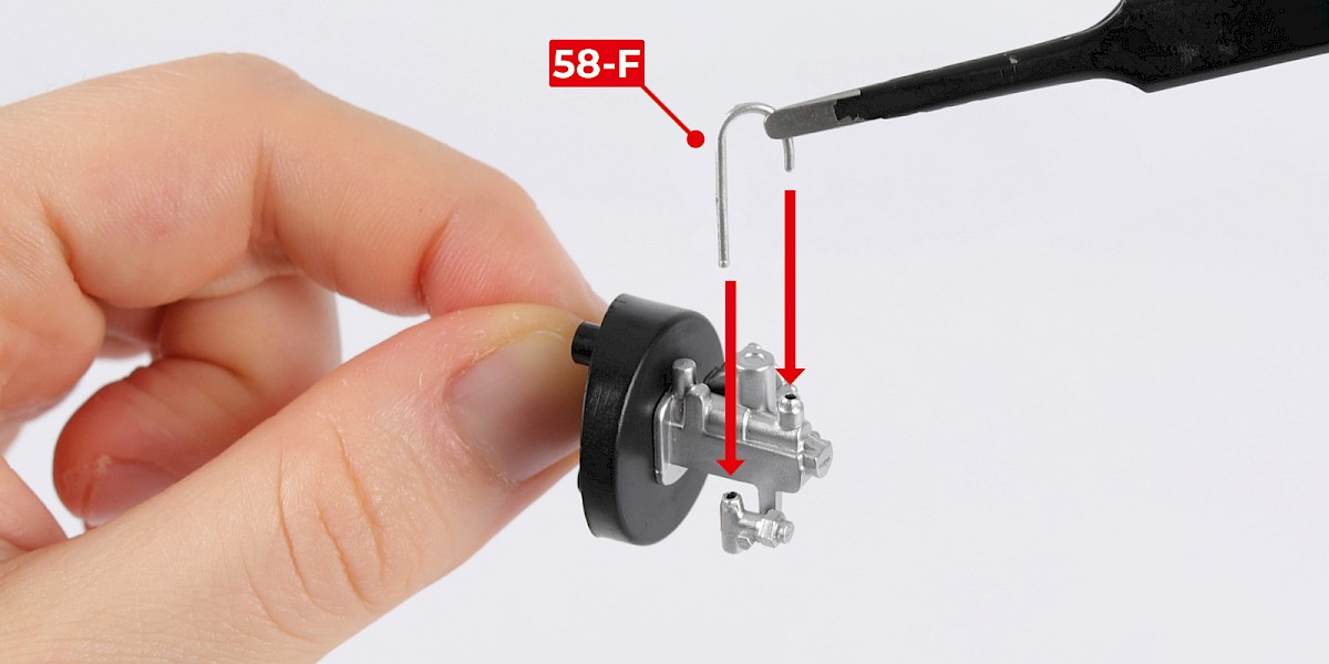
Step 3
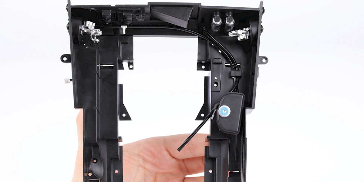
Fit the J-connector (58-F) to the assembly.
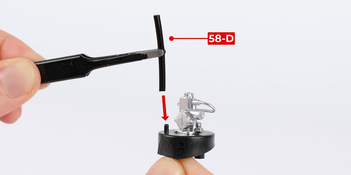
Step 4
Fit the hose (58-D) to the assembly.
Step 5
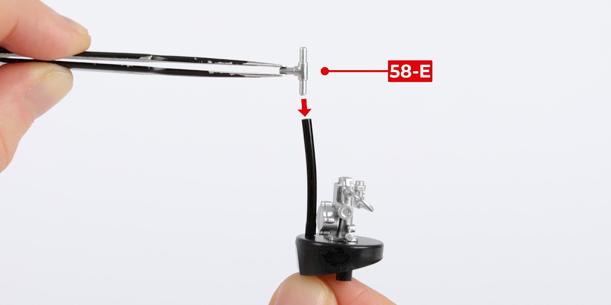
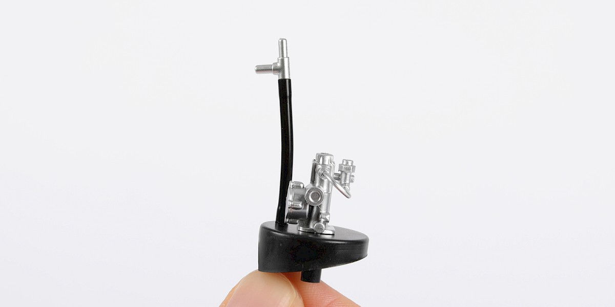
Fit the T-connector (58-E) to the hose.
Step 6
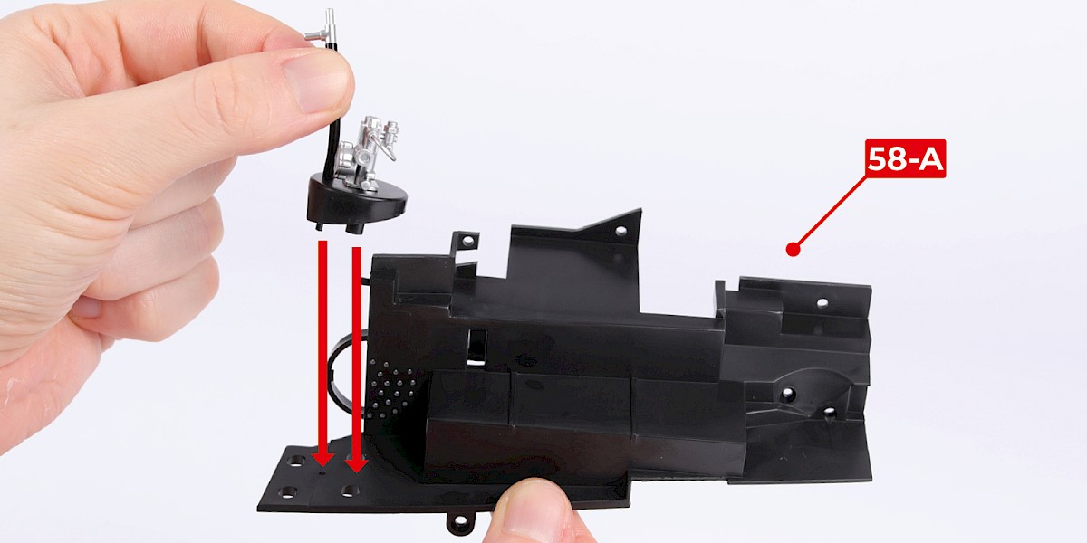
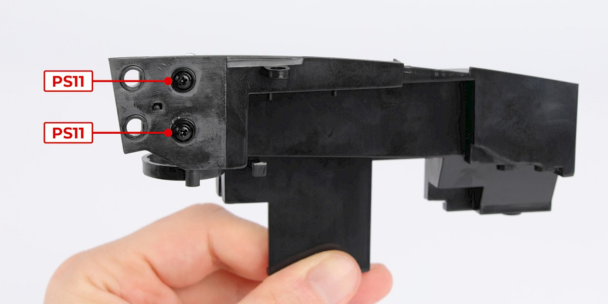
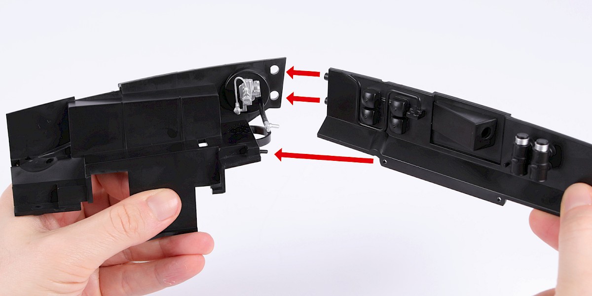
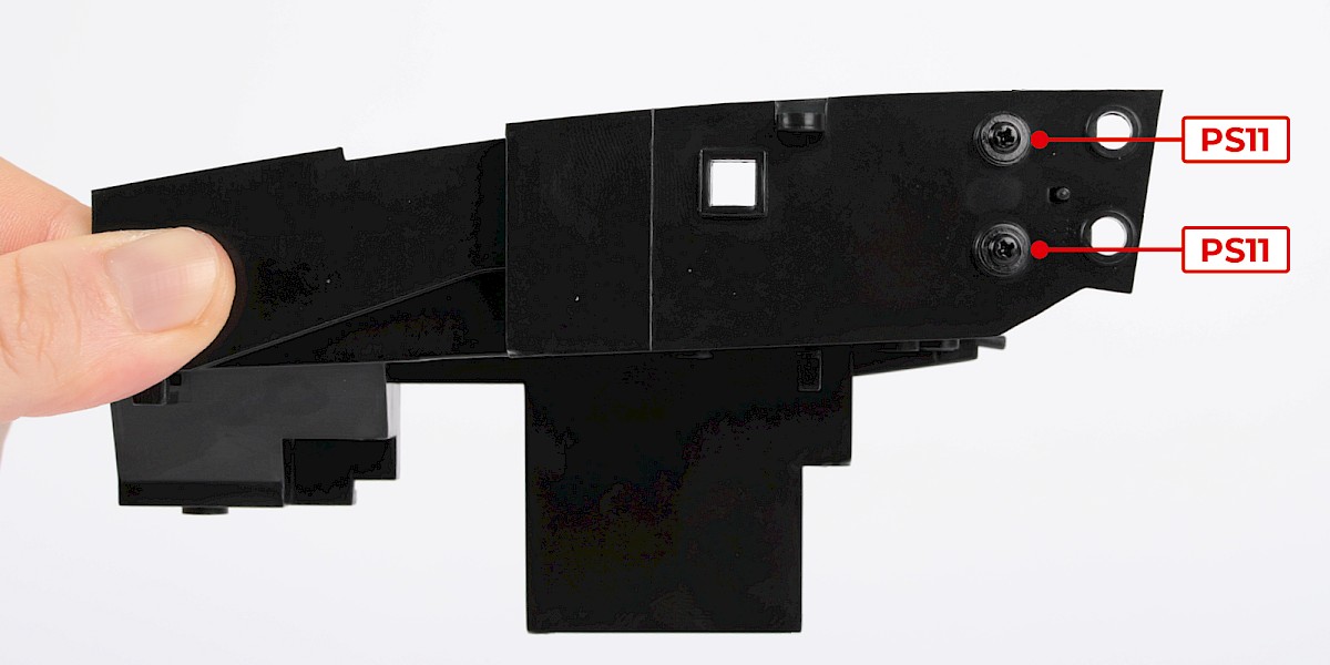
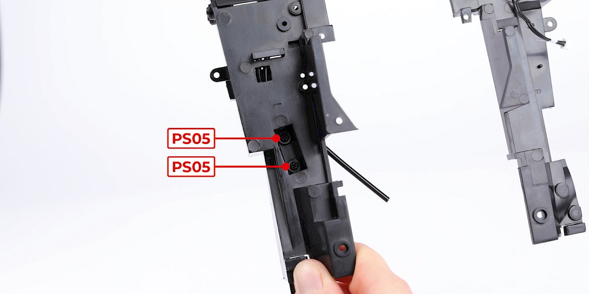
Fit the assembly to the engine bay wall (58-A).
Step 7
Secure with 2x PS11.
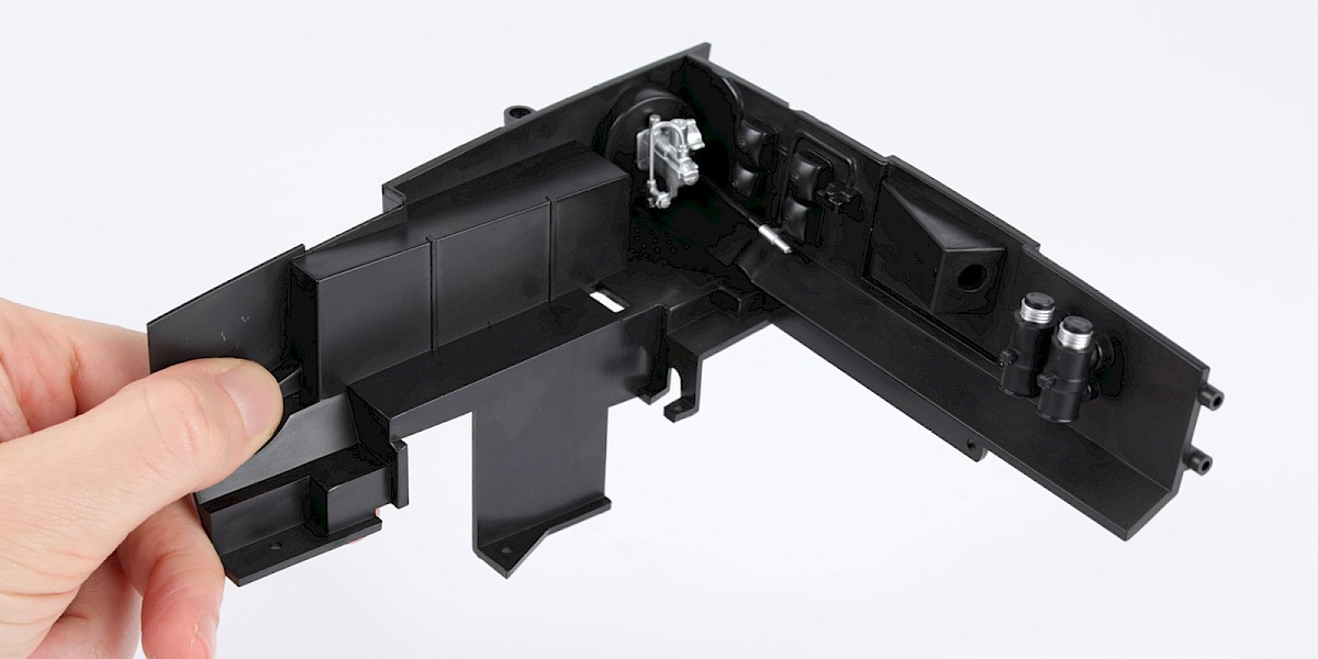
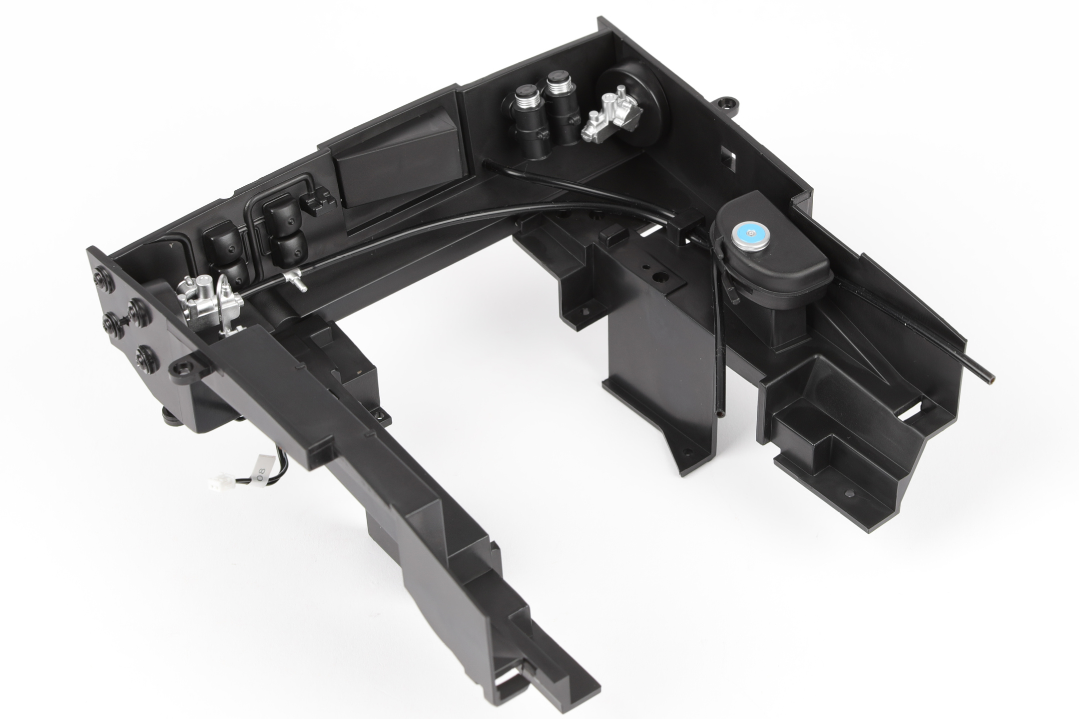
STAGE COMPLETE
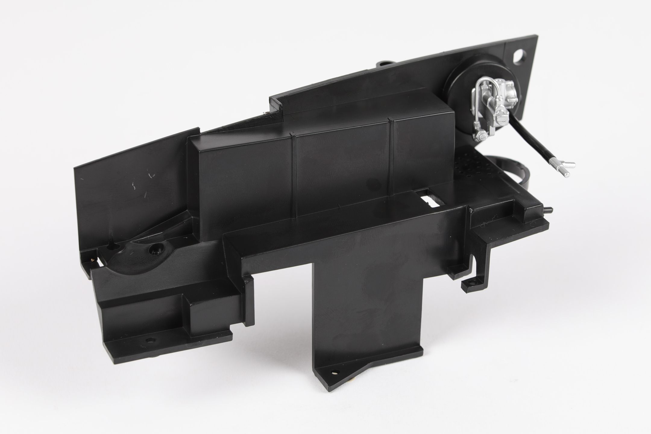
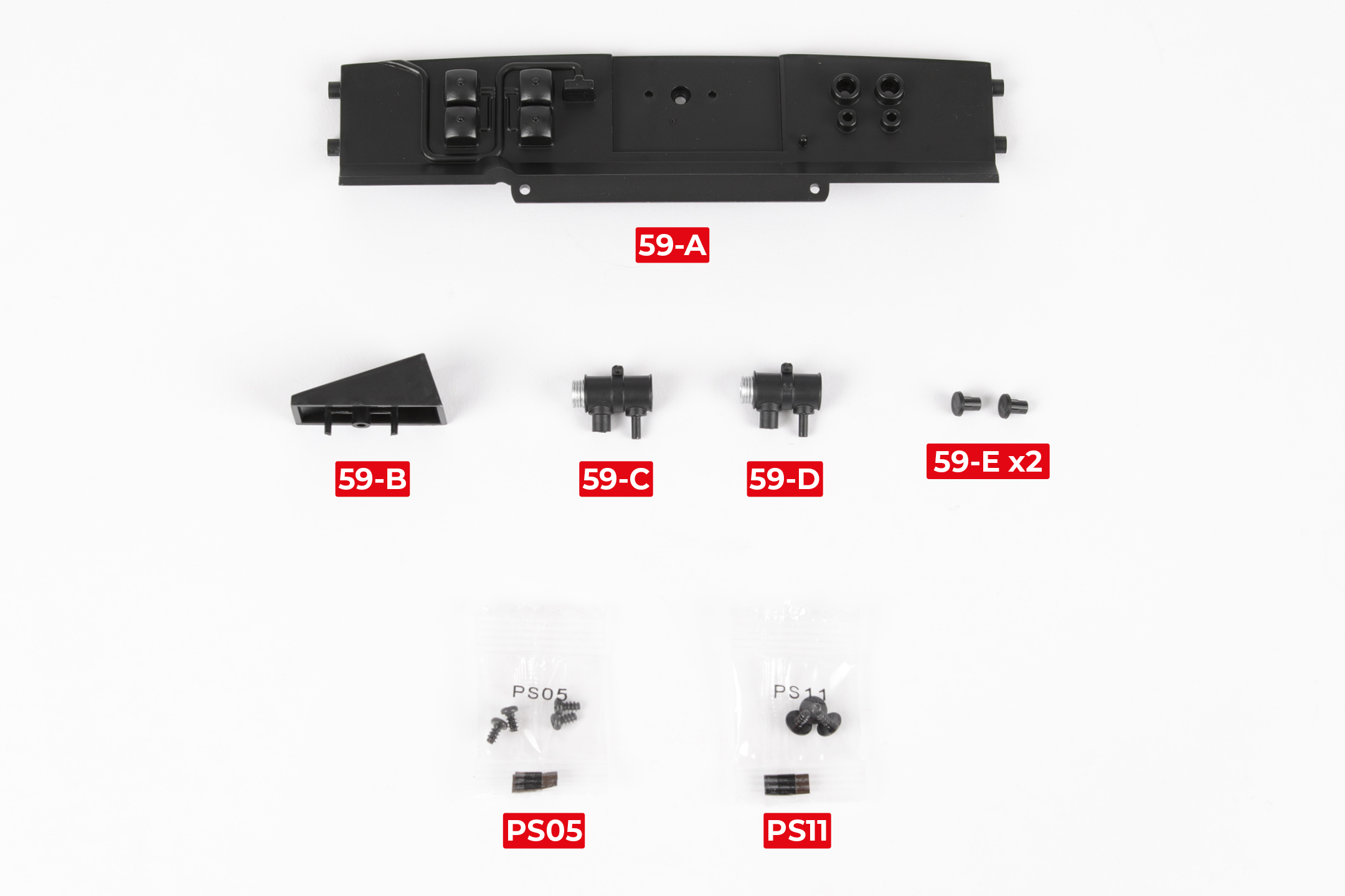
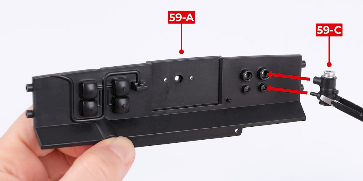
PARTS LIST
| 59-A Firewall | 59-E Reservoir cap x2 |
| 59-B Heater blower housing | 4x PS05 screws |
| 59-C Brake fluid reservoir | 3x PS11 screws |
| 59-D Brake fluid reservoir |
Step 1
Fit a brake fluid reservoir (59-C) to the firewall (59-A).
Note: The brake fluid reservoirs (59-C and 59-D) are identical.
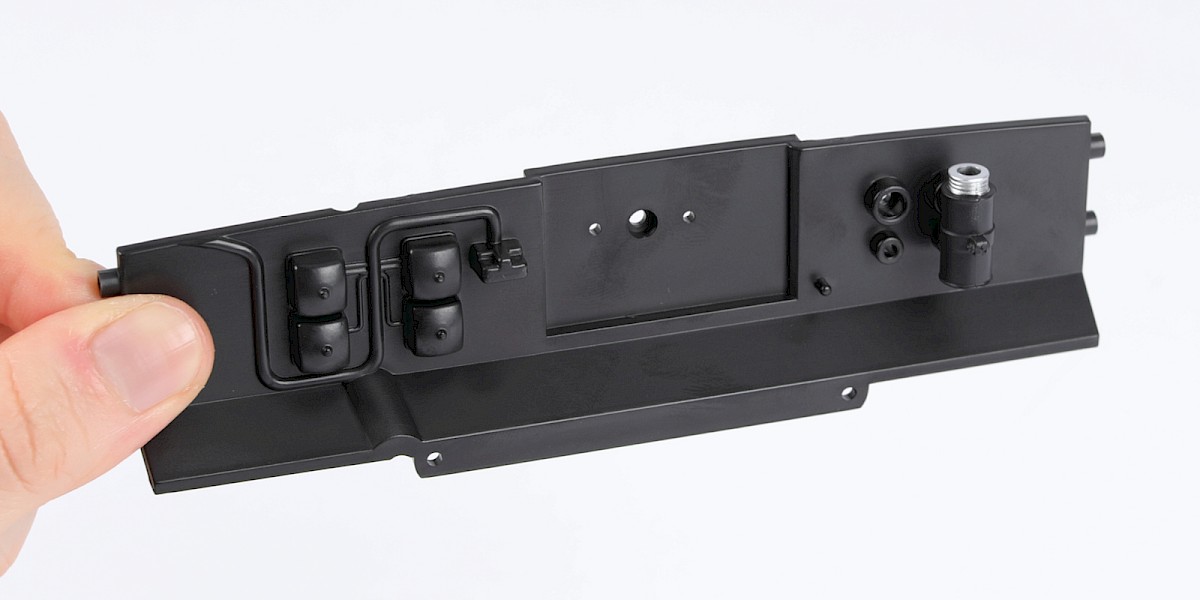
Step 2
Fit the other brake fluid reservoir (59-D) to the assembly.
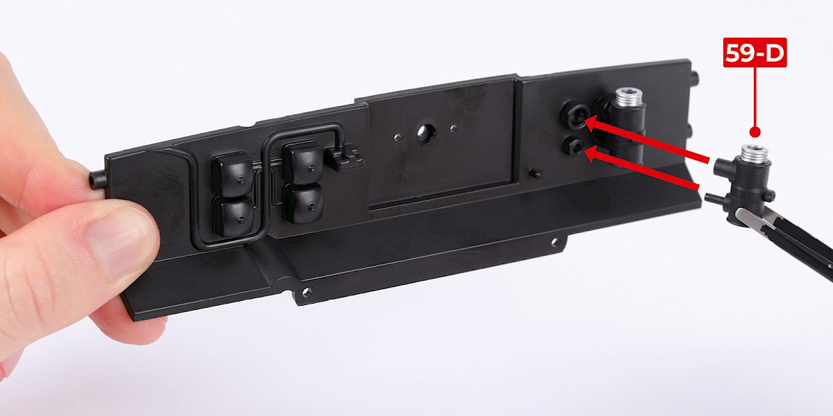
Step 3
Secure from the other side with 2x PS05.
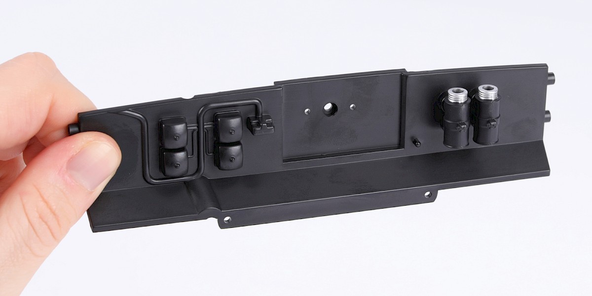
Step 4
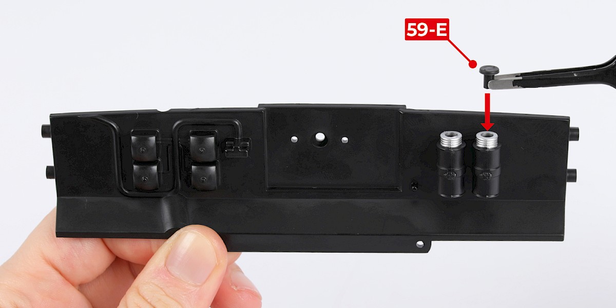
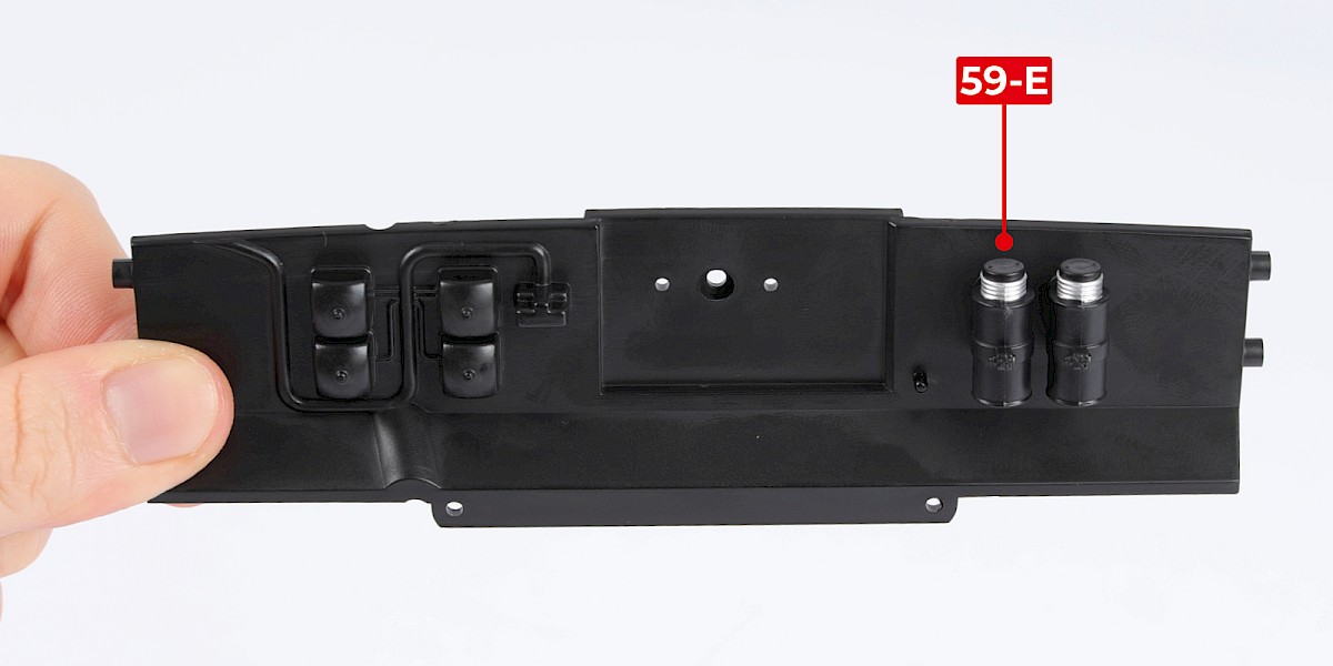
Fit a brake reservoir cap (59-E) onto each brake reservoir as shown.
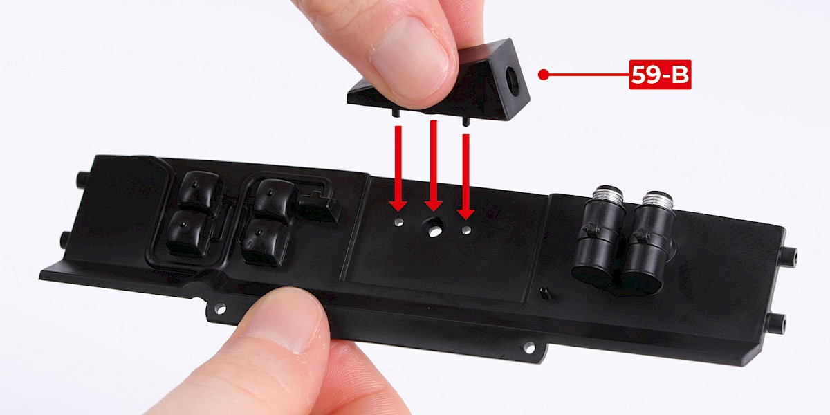
Step 5
Fit the heater blower housing (59-B) to the assembly.
Step 6
Secure from the other side with 1x PS05.
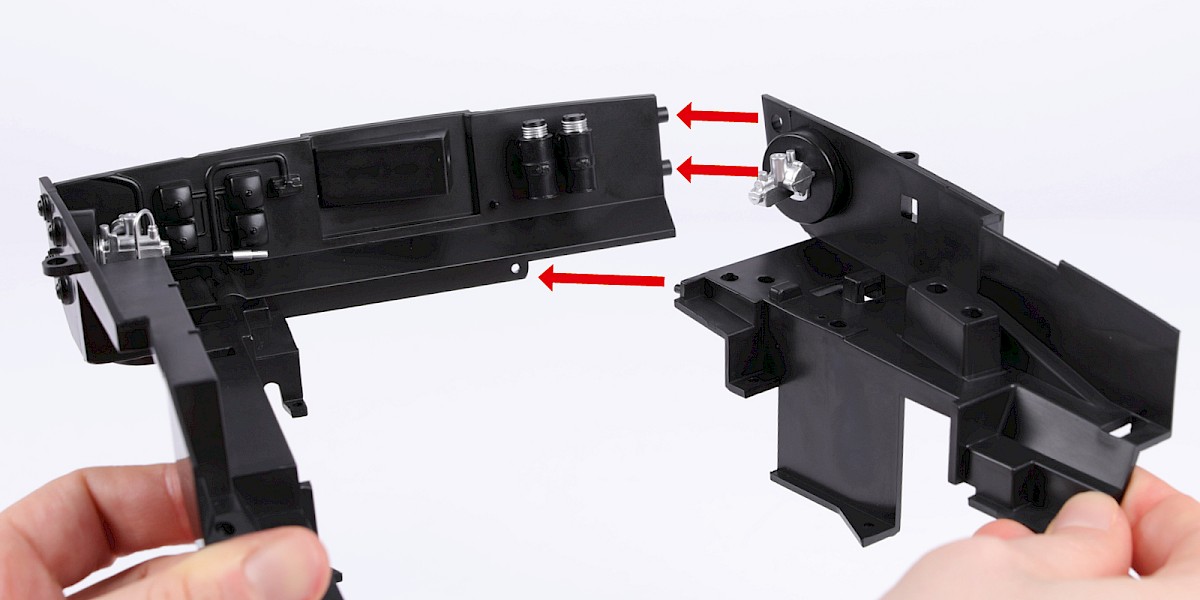
Step 7
Fit the firewall to the engine bay assembly (stage 058).
Step 8
Secure with 2x PS11.
STAGE COMPLETE
PARTS LIST
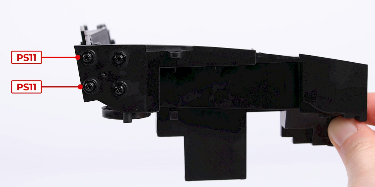
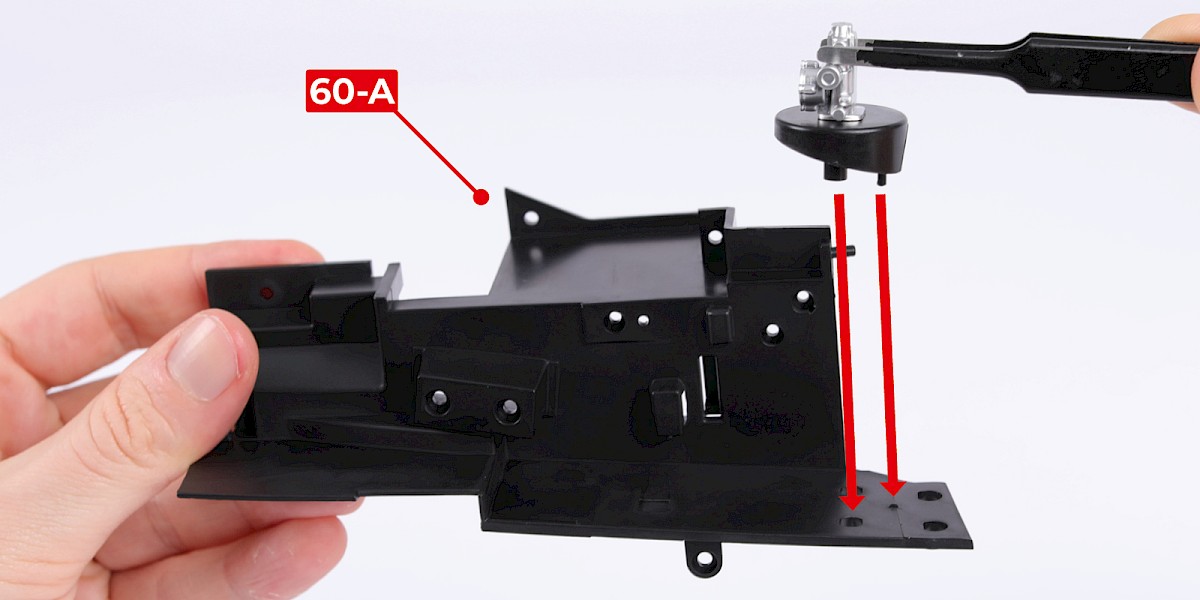
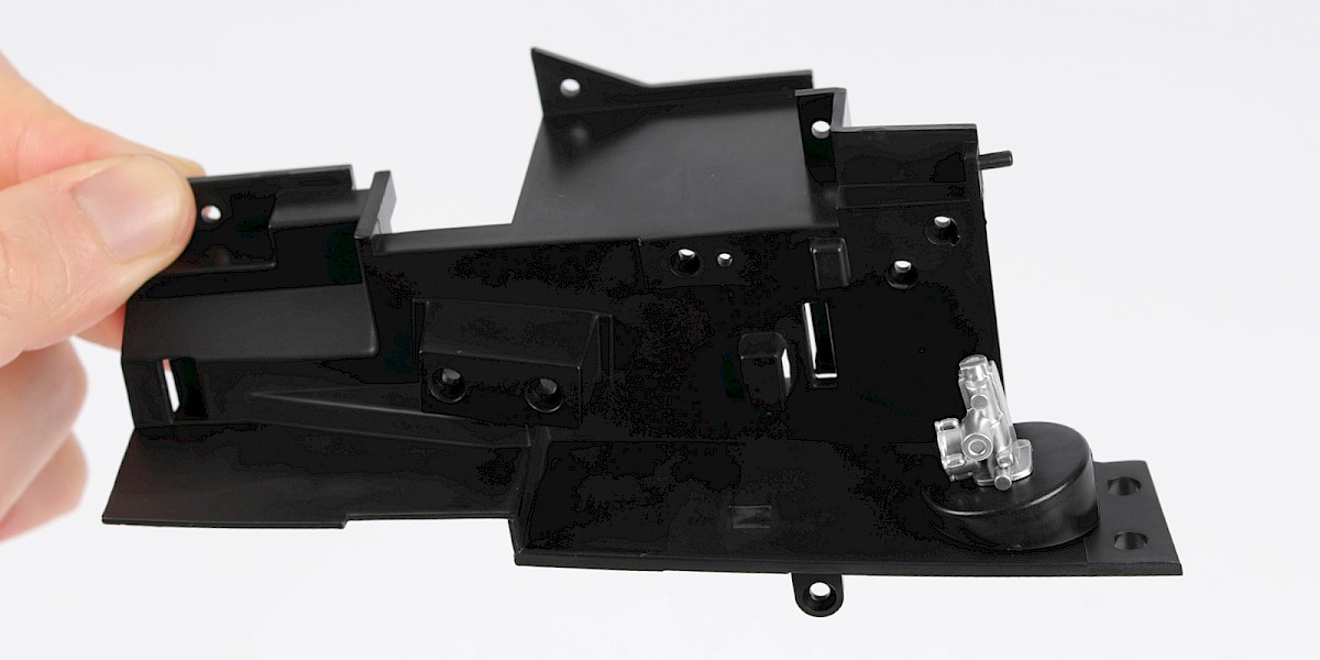
| 60-A Engine bay wall (left) |
| 60-B Brake servo mount |
| 60-C Brake servo |
| 2x PS05 screws |
| 5x PS11 screws |
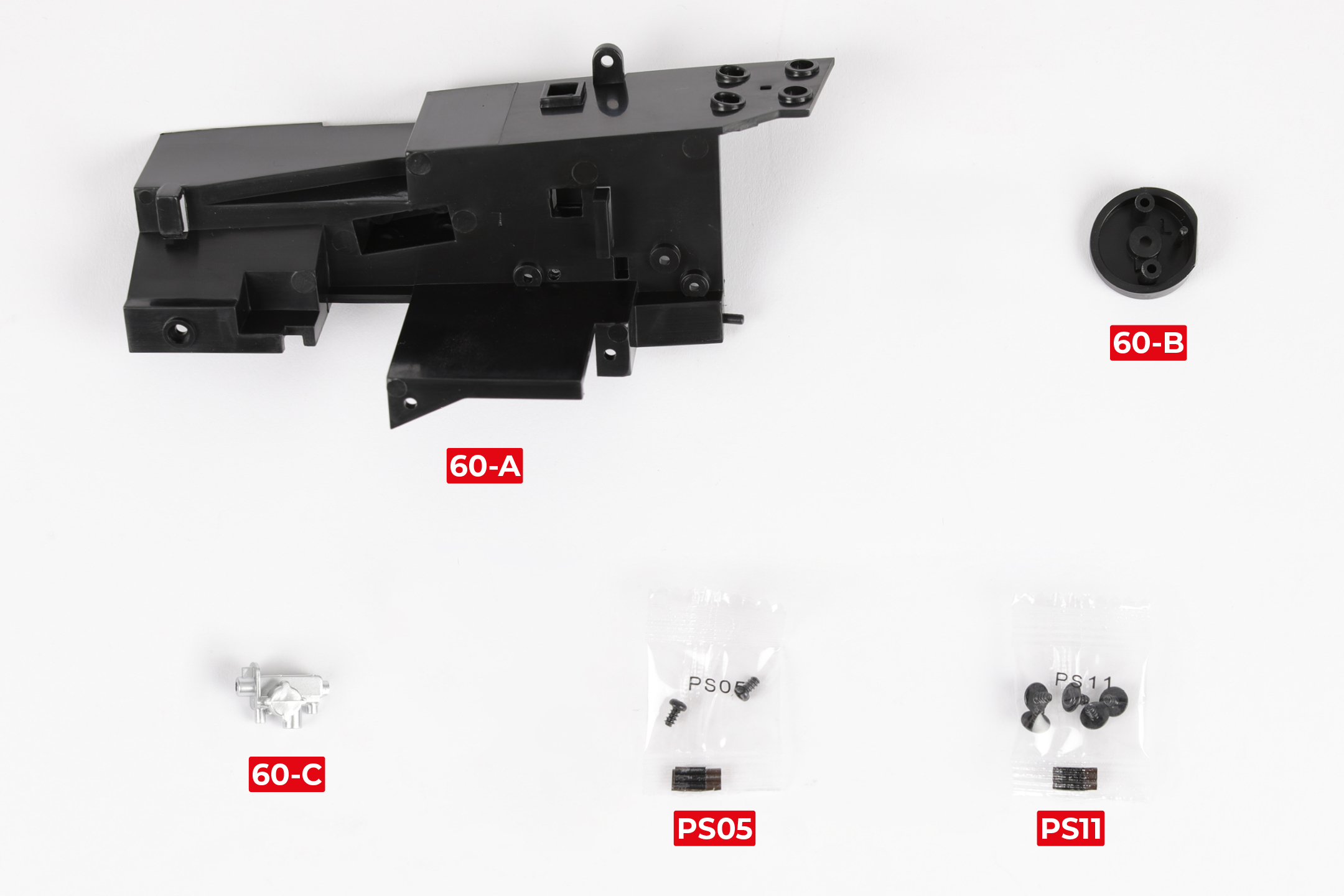
Step 1
Fit the brake servo (60-C) to the brake servo mount (60-B).
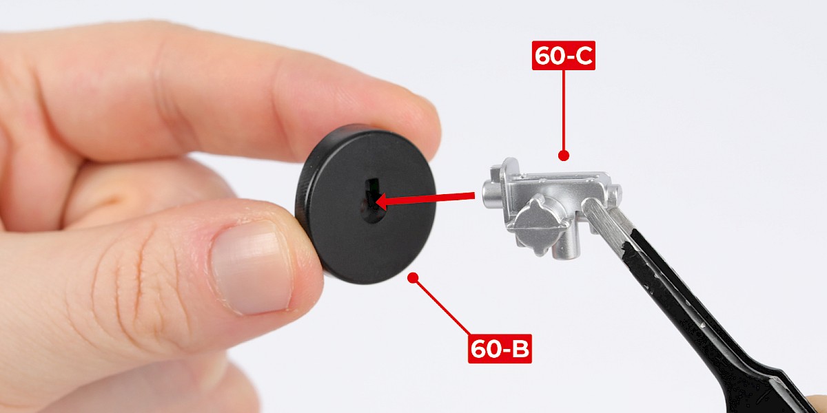
Step 2
Secure with 1x PS05.
Step 3
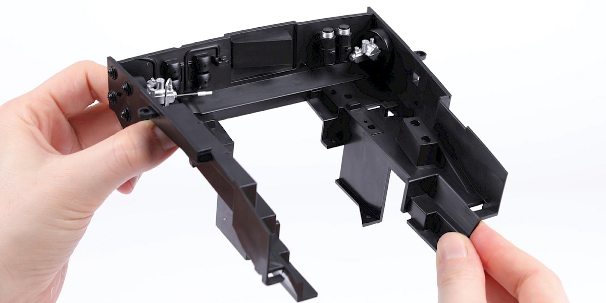
Fit the assembly to the engine bay wall (60-A).
Step 4
Secure with 2x PS11.
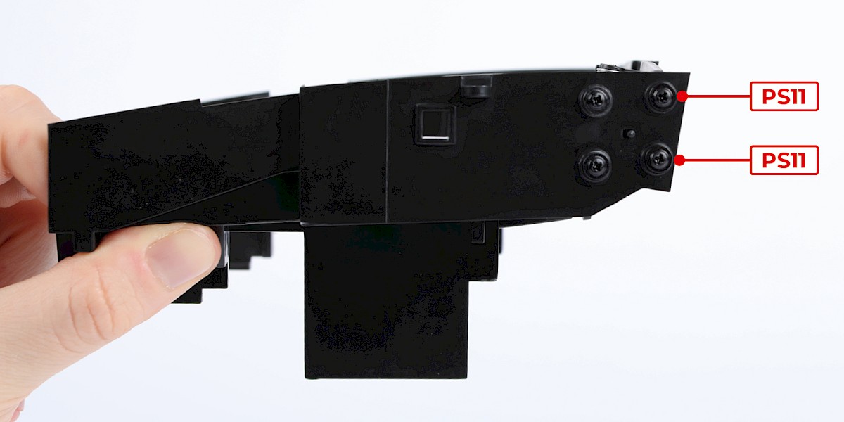
Step 5
Fit the assembly onto the firewall (stage 059).
Step 6
Secure with 2x PS11.
STAGE COMPLETE
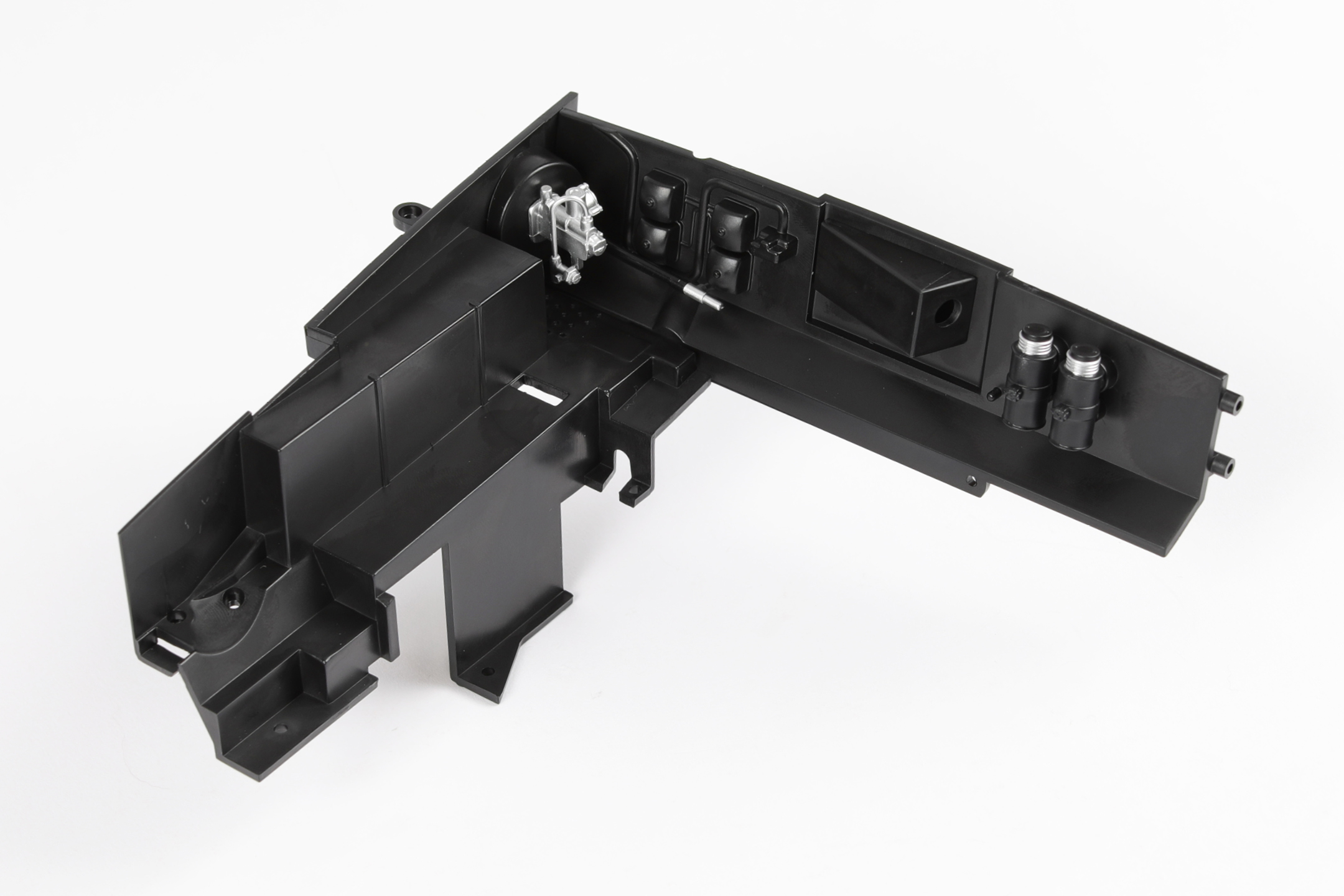
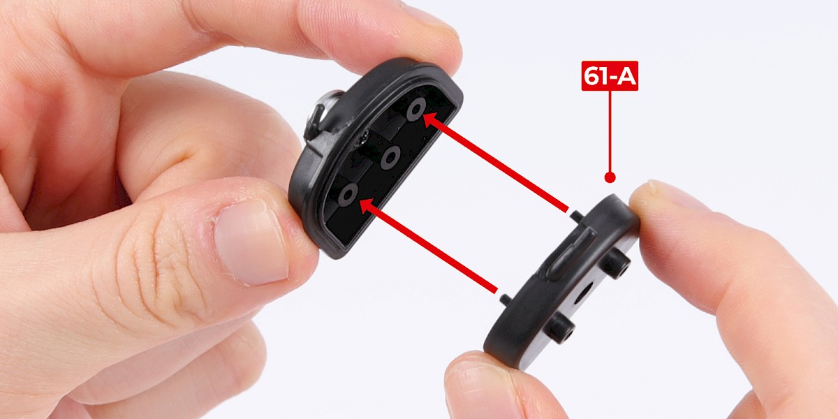
PARTS LIST
| 61-A Radiator header tank (bottom) | 61-E Speaker |
| 61-B Radiator header tank (top) | 61-F Long hose |
| 61-C Cap | 61-G Short hose |
| 61-D Speaker holder | 7x PS05 screws |
Step 1
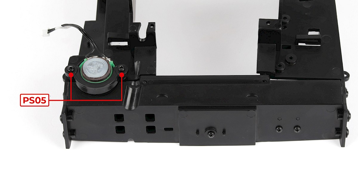
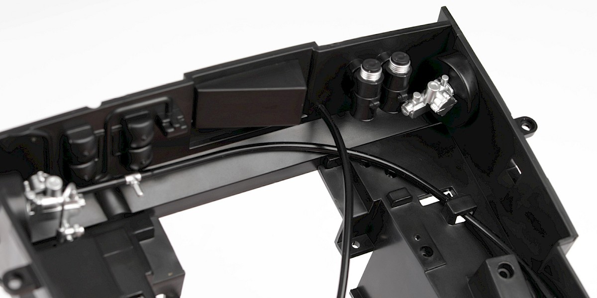
Fit the speaker (61-E) onto the engine bay assembly (stage 060).
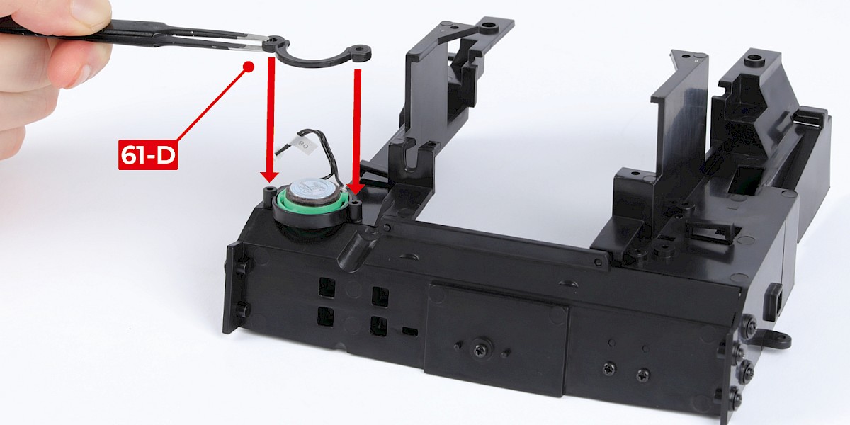
Step 2
Fit the speaker holder (61-D) to the assembly.
Secure with 2x PS05.
Step 3
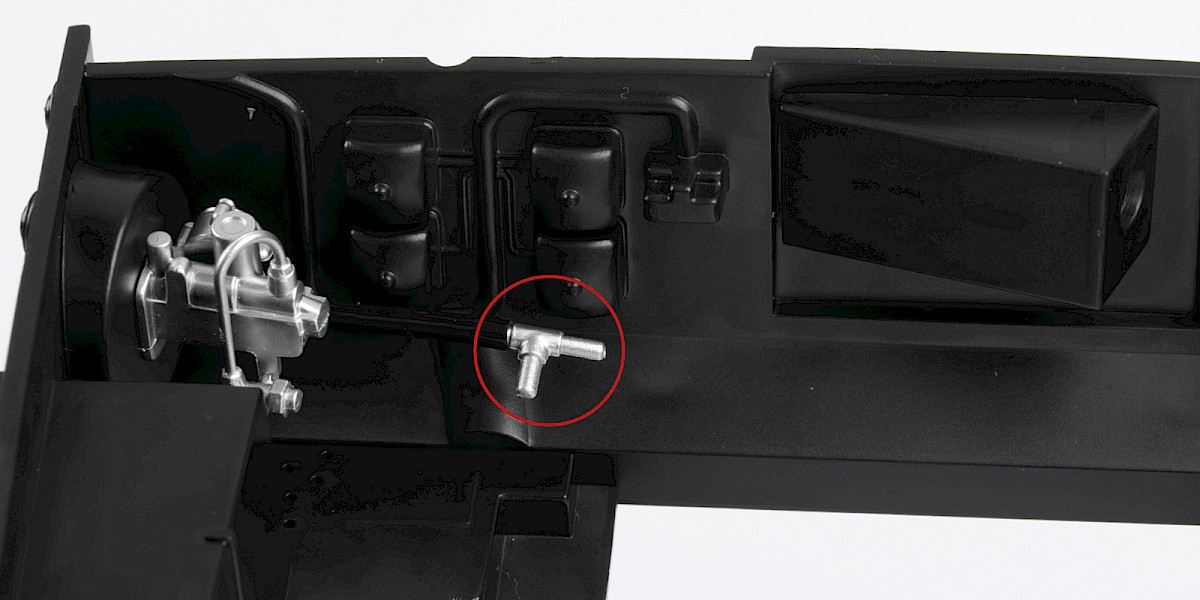
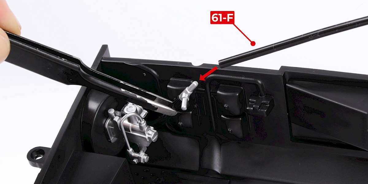
If necessary, turn the T-connector so that it is in the orientation shown.
Fit the long hose (61-F) to the T-connector.
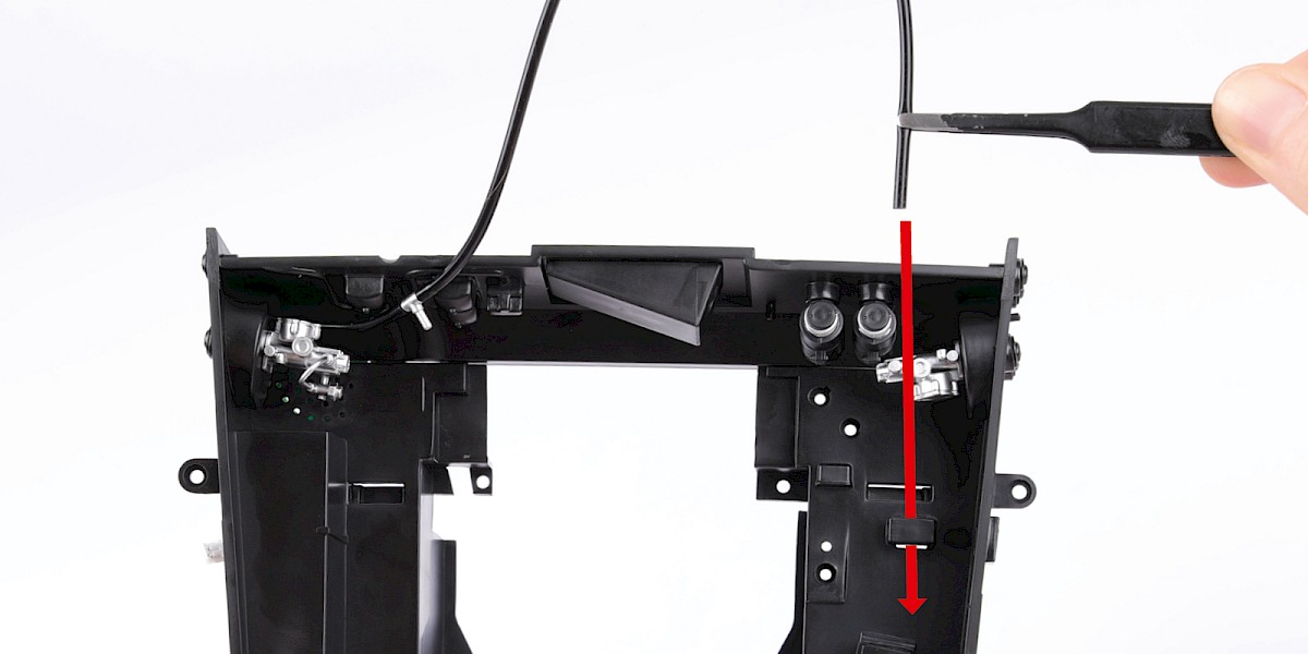
Step 4
Thread the long hose through the engine bay as shown.
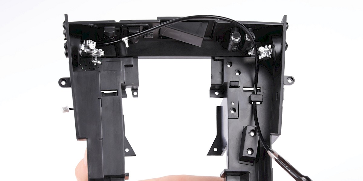
Step 5
Position the long hose as indicated.
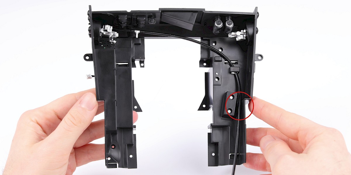
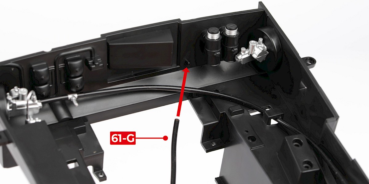
Step 6
Fit the short hose (61-G) to the assembly.
Step 7
Thread the short hose through the assembly and position it as shown.
Step 8
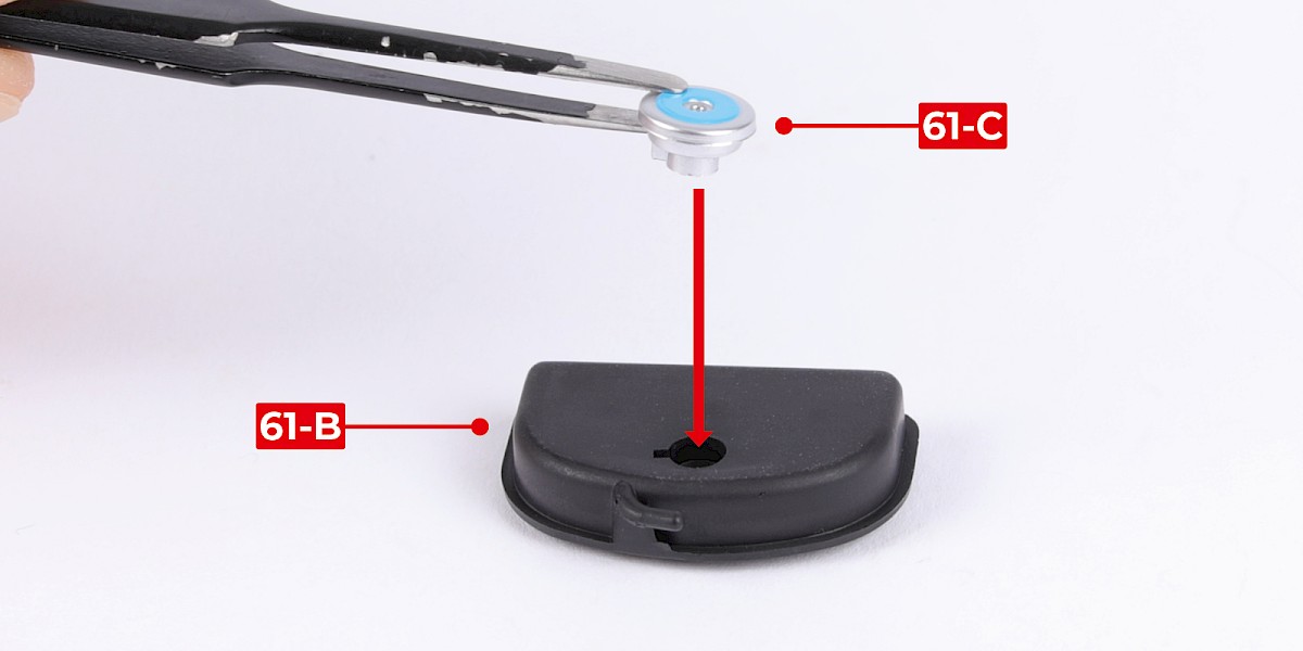
Fit the cap (61-C) into the top of the header tank (61-B).
Step 9
Secure from underneath with 1x PS05.
Step 10
Fit the bottom of the header tank (61-A) to the assembly.
Secure with 1x PS05.
Step 11
Fit the assembly to the engine bay.
Note that the long and short pipes should remain on both sides of the rectangular mount.
Step 12
Secure from underneath with 2x PS05.
STAGE COMPLETE
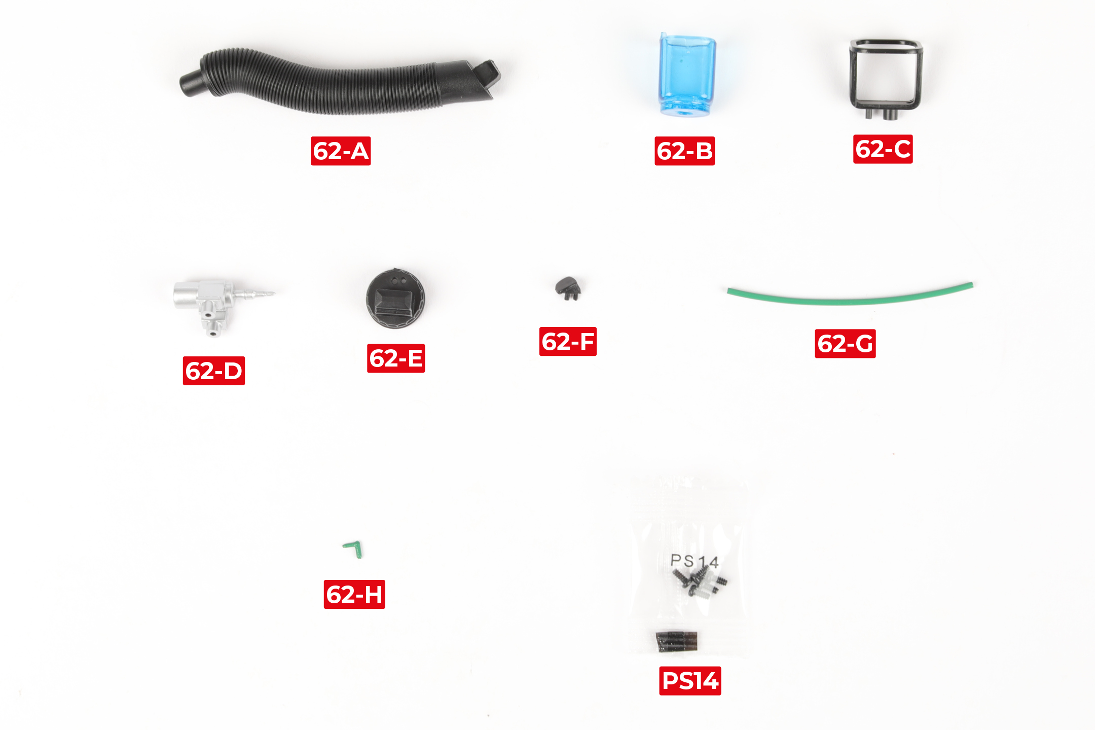
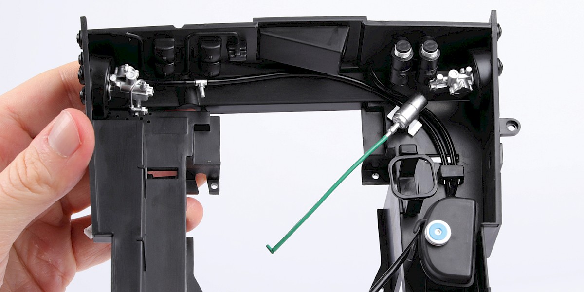
PARTS LIST
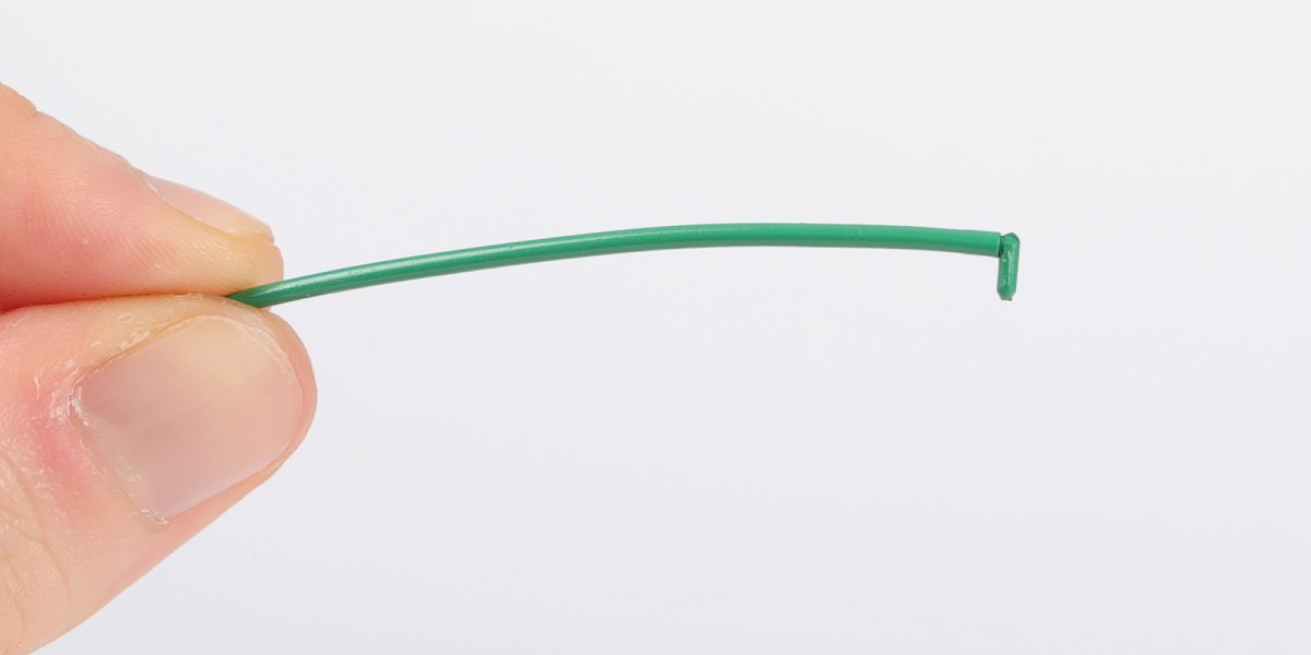
| 62-A Air vent trunk | 62-F Cap |
| 62-B Windscreen washer reservoir | 62-G Lead |
| 62-C Holder | 62-H L-connector |
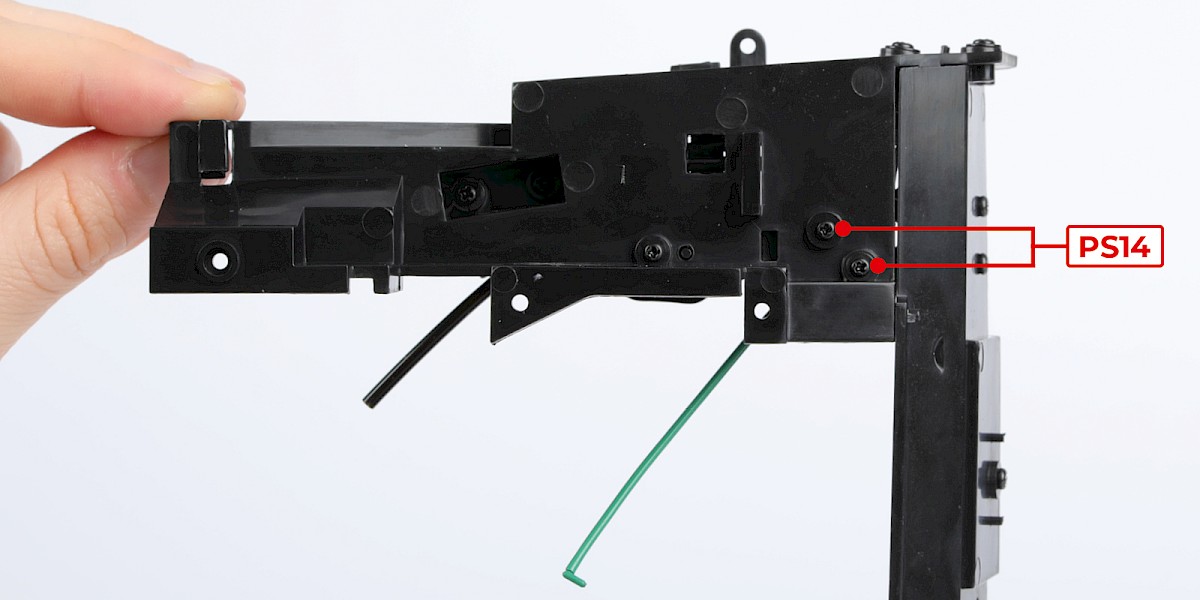
| 62-D Ignition coil | 5x PS14 screws |
| 62-E Lid |
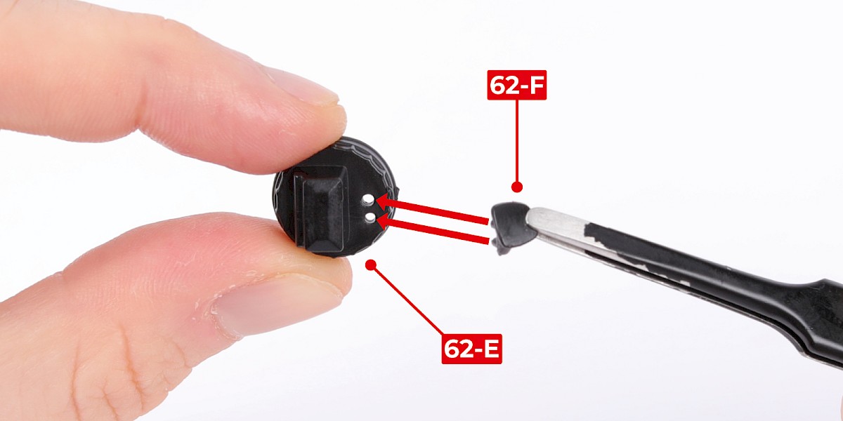
Step 1
Fit the cap (62-F) onto the lid (62-E).
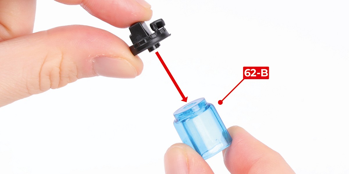
Step 2
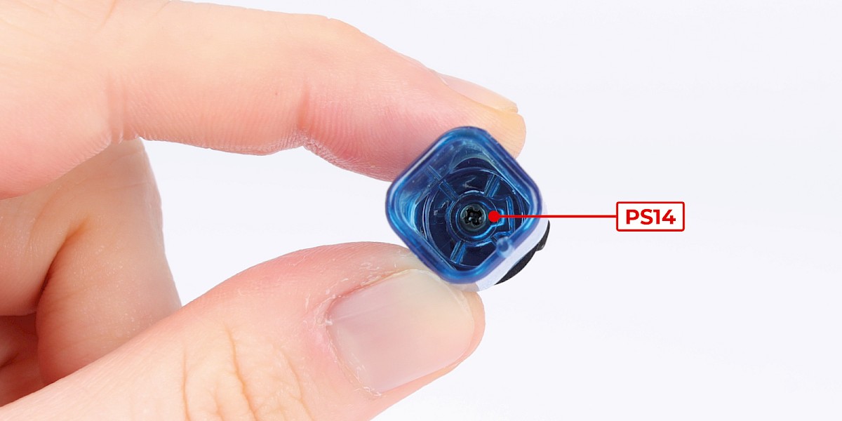
Fit the lid onto the windscreen washer reservoir (62-B).
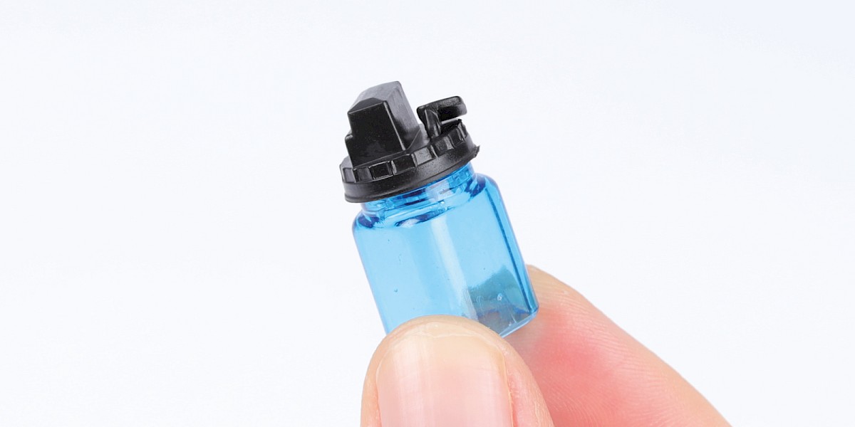
Step 3
Secure with 1x PS14.
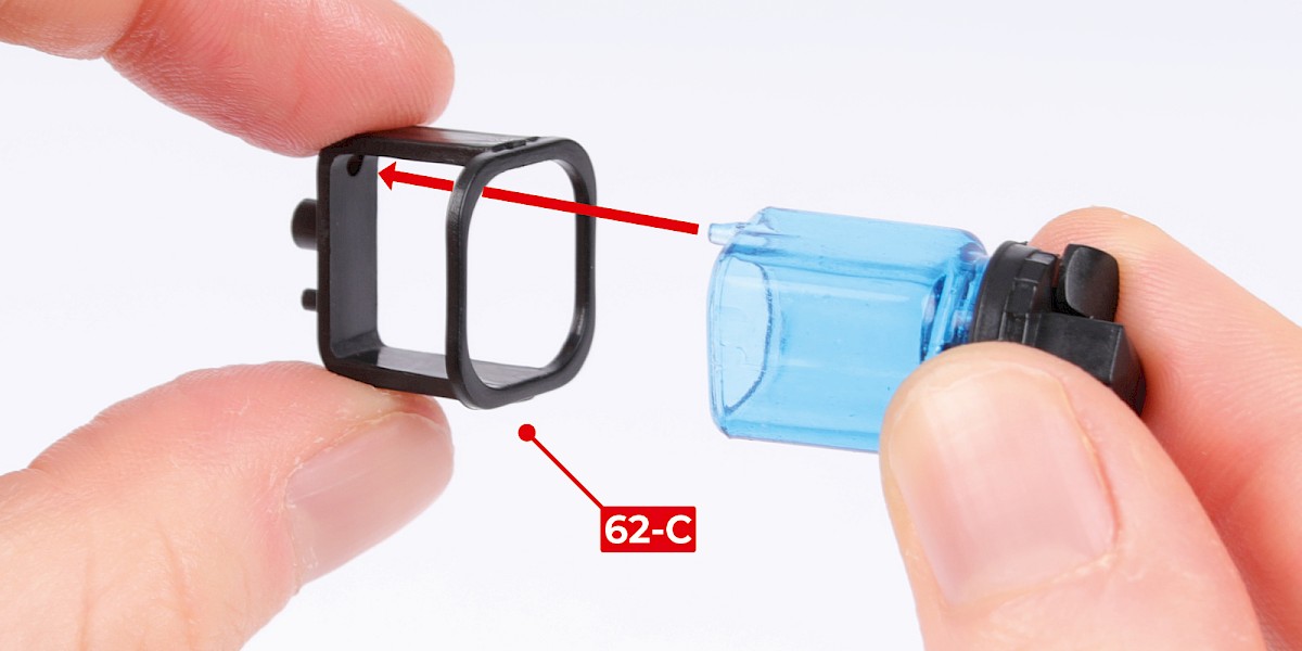
Step 4
Fit the assembly into the holder (62-C).
Note: The windscreen washer reservoir is not fixed in place. You may prefer to keep the windscreen washer reservoir in a safe place then fit it when your model is complete.
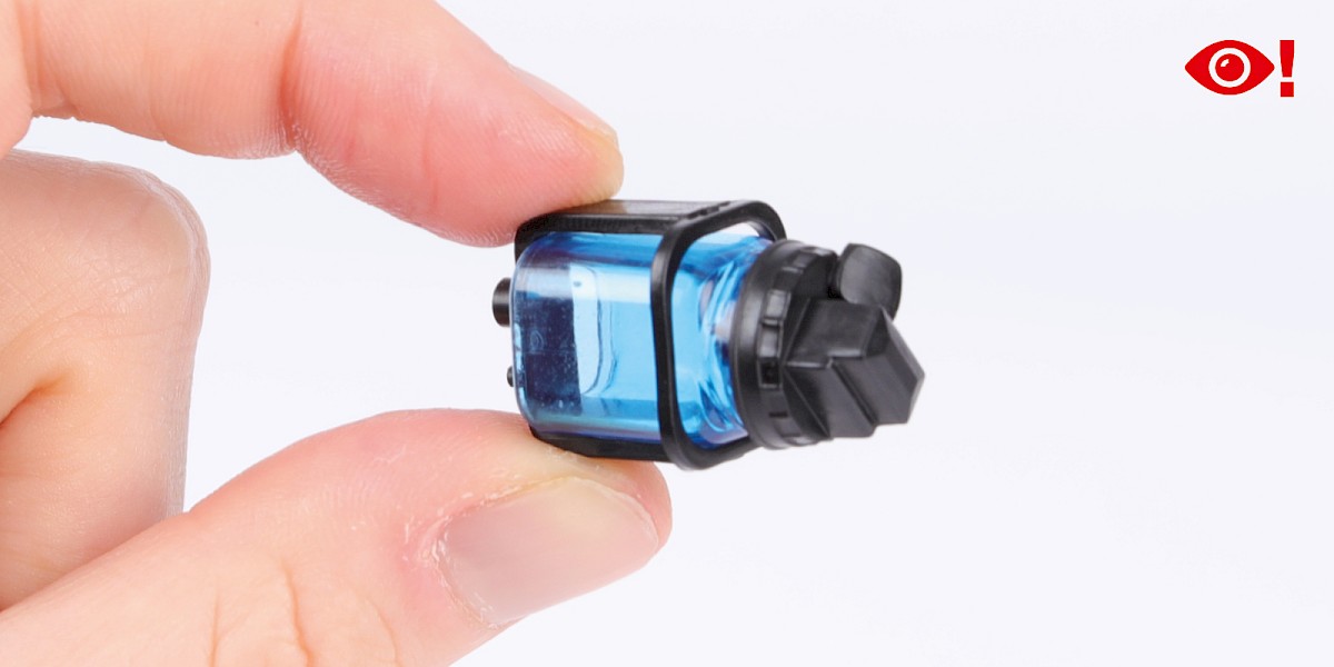
Step 5
Fit the holder to the engine bay assembly (stage 061).
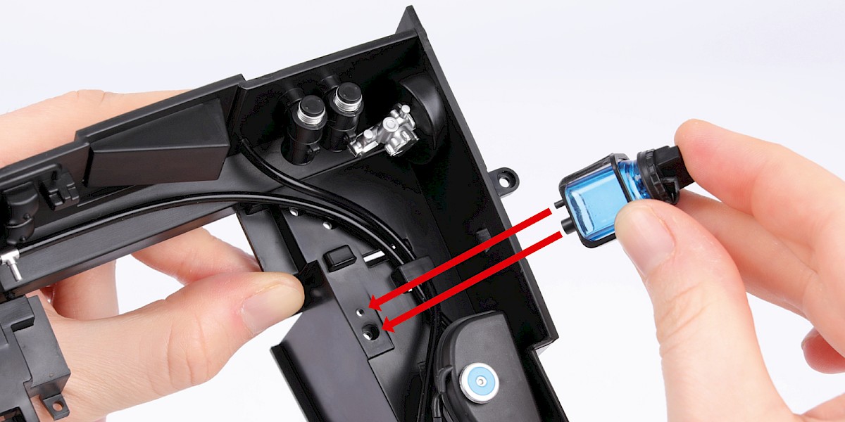
Step 6
Secure from underneath with 1x PS14.
Step 7
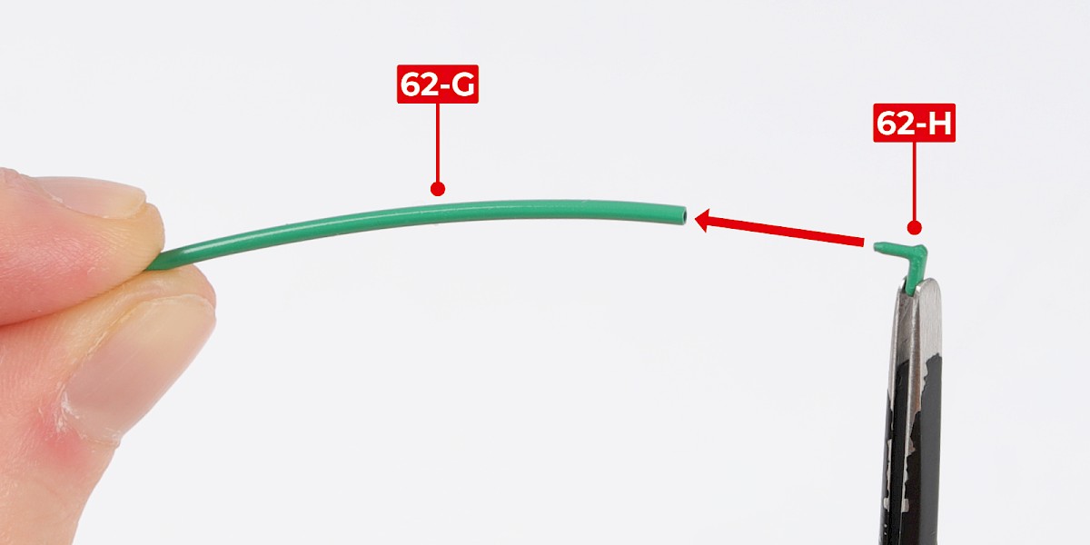
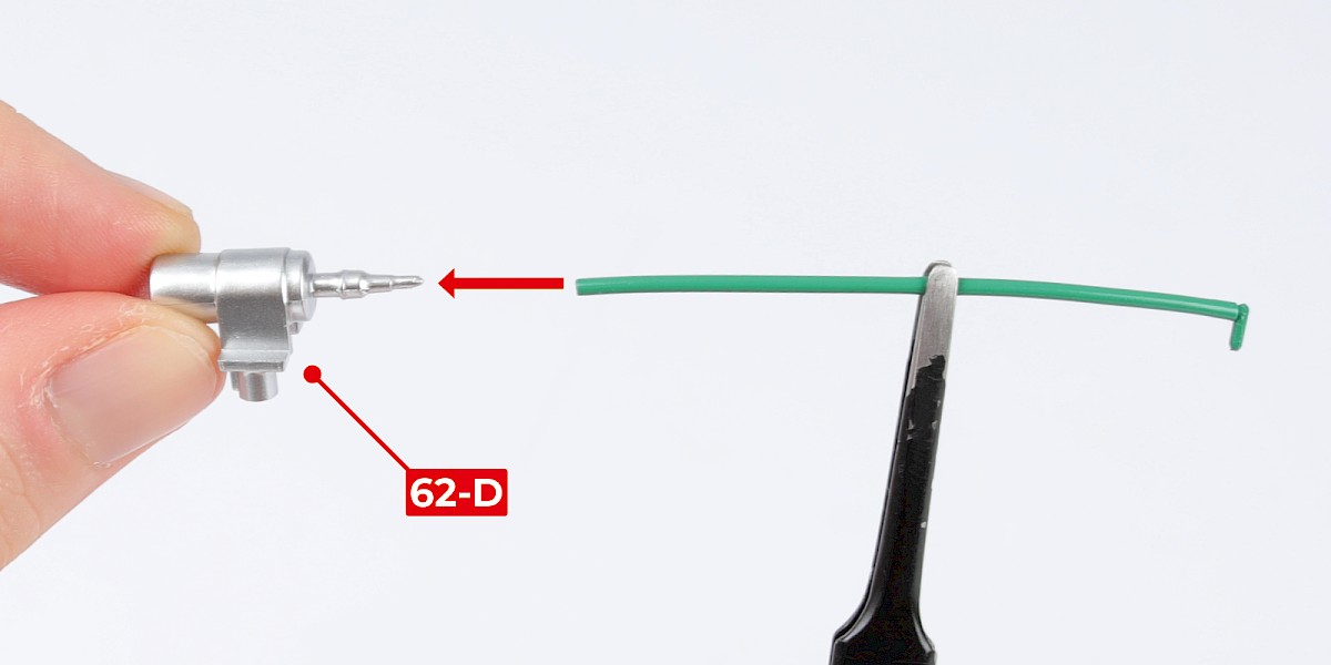
Fit the L-connector (62-H) into the lead (62-G).
Step 8
Fit the lead to the ignition coil (62-D).
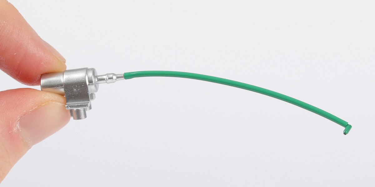
Step 9
Fit the ignition coil to the engine bay.
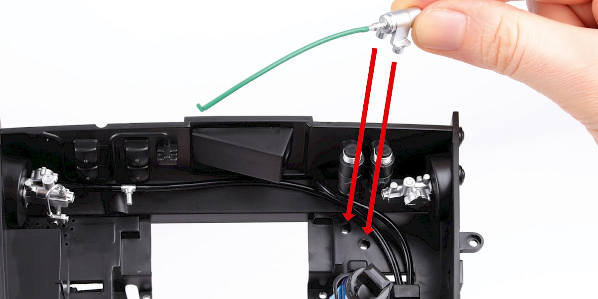
Step 10
Secure with 2x PS14.
Step 11
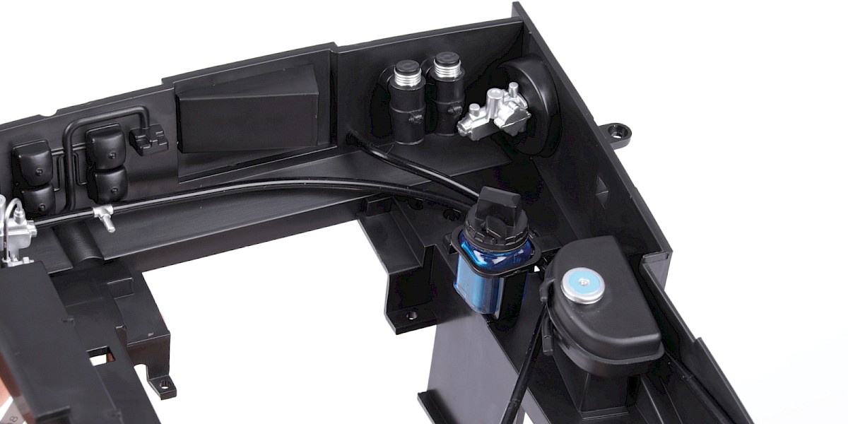
Fit the air vent trunk (62-A) to the assembly.
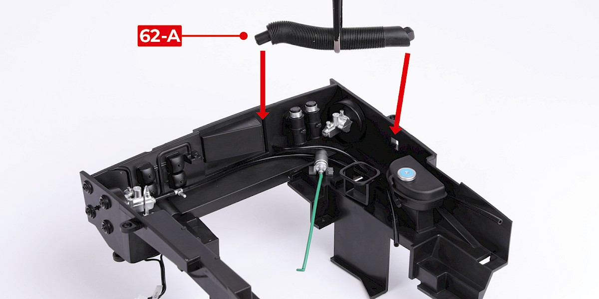
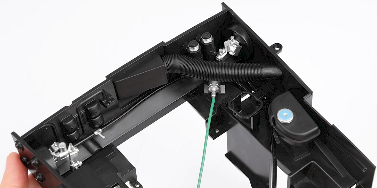
STAGE COMPLETE
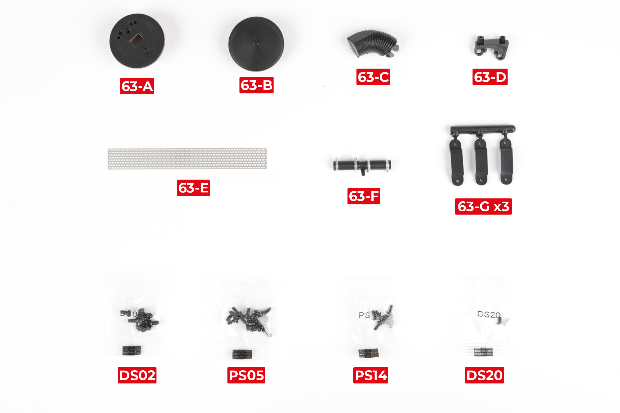
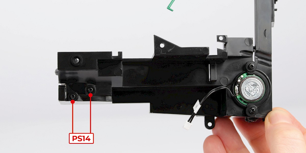
PARTS LIST
| 63-A Air filter bottom | 63-G Cable fastener x3 |
| 63-B Air filter top | 8x DS02 screws |
| 63-C Tube | 13x PS05 screws |
| 63-D Mount | 7x PS14 screws |
| 63-E Grille | 2x DS20 screws |
| 63-F Pipe |
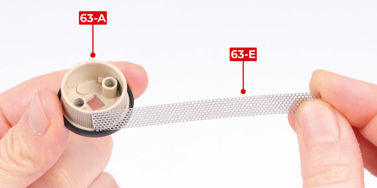
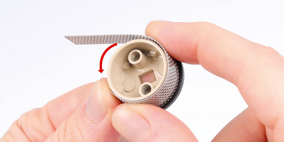
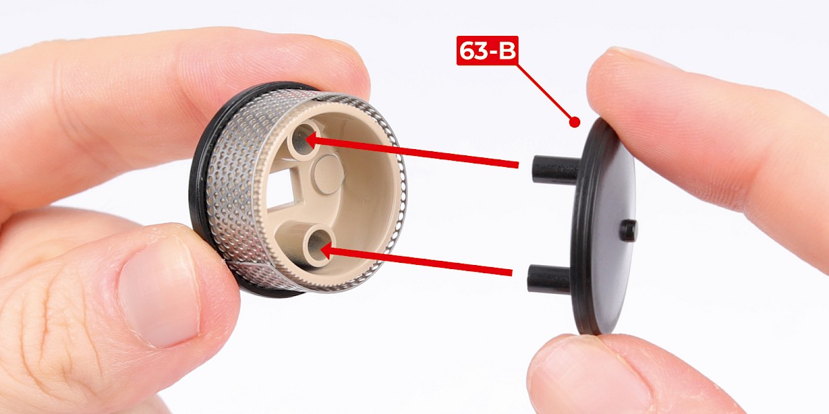
Step 1
Fit the grille (63-E) to the air filter bottom (63-A).
Wrap the grille around the air filter bottom.
Step 2
Fit the air filter top (63-B) to the assembly.
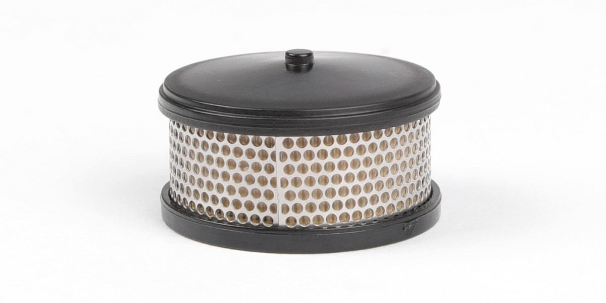
Step 3
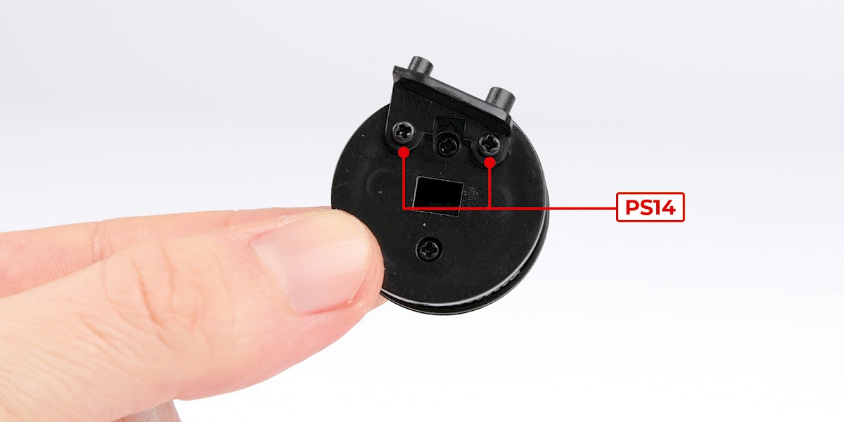
Secure with 2x PS14.
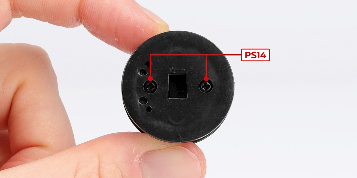
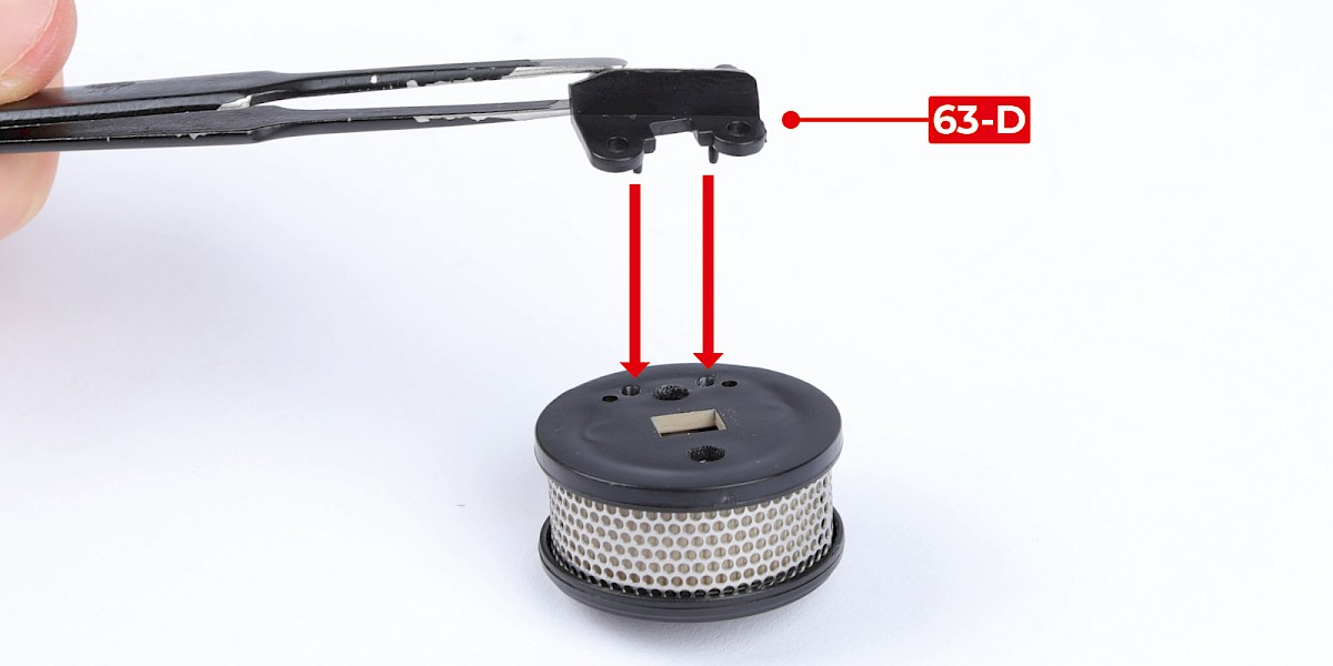
Step 4
Fit the mount (63-D) to the assembly.
Secure with 2x PS14.
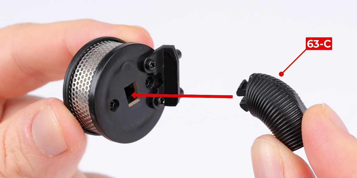
Step 5
Fit the tube (63-C) to the assembly.
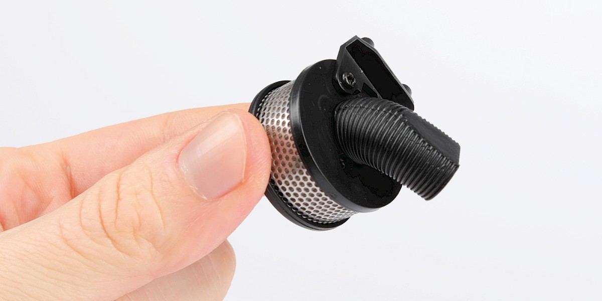
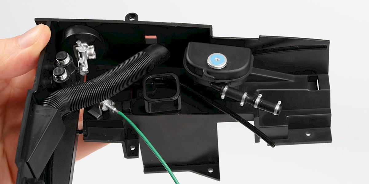
Step 6
Fit the assembly to the engine bay (stage 062).
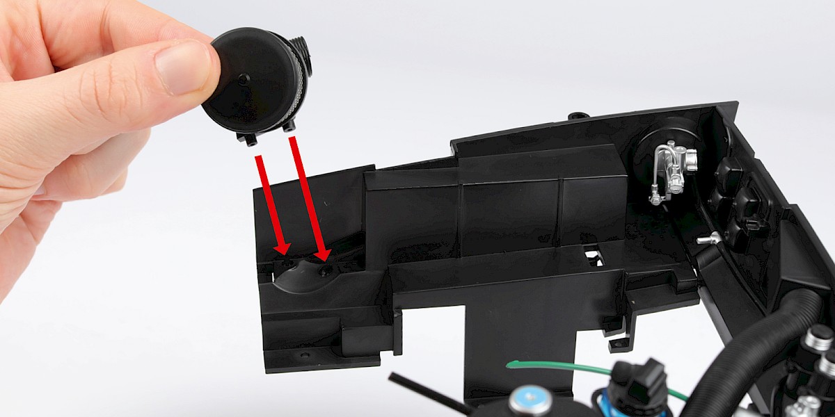
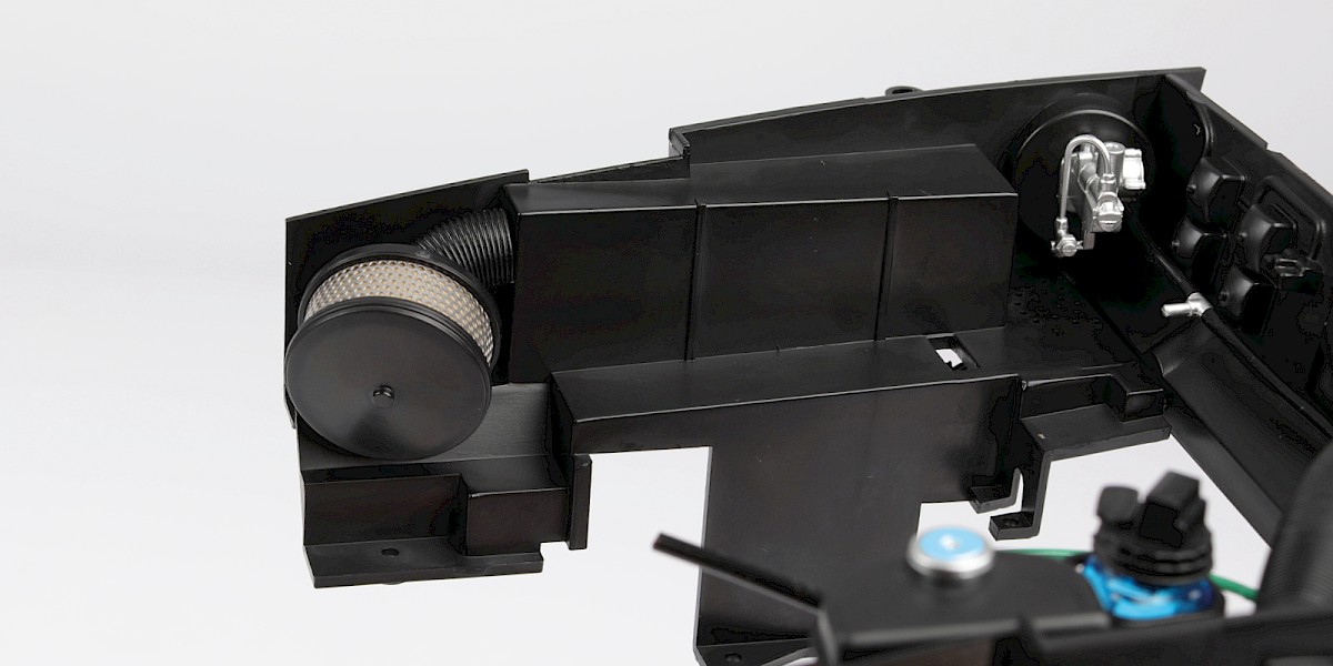
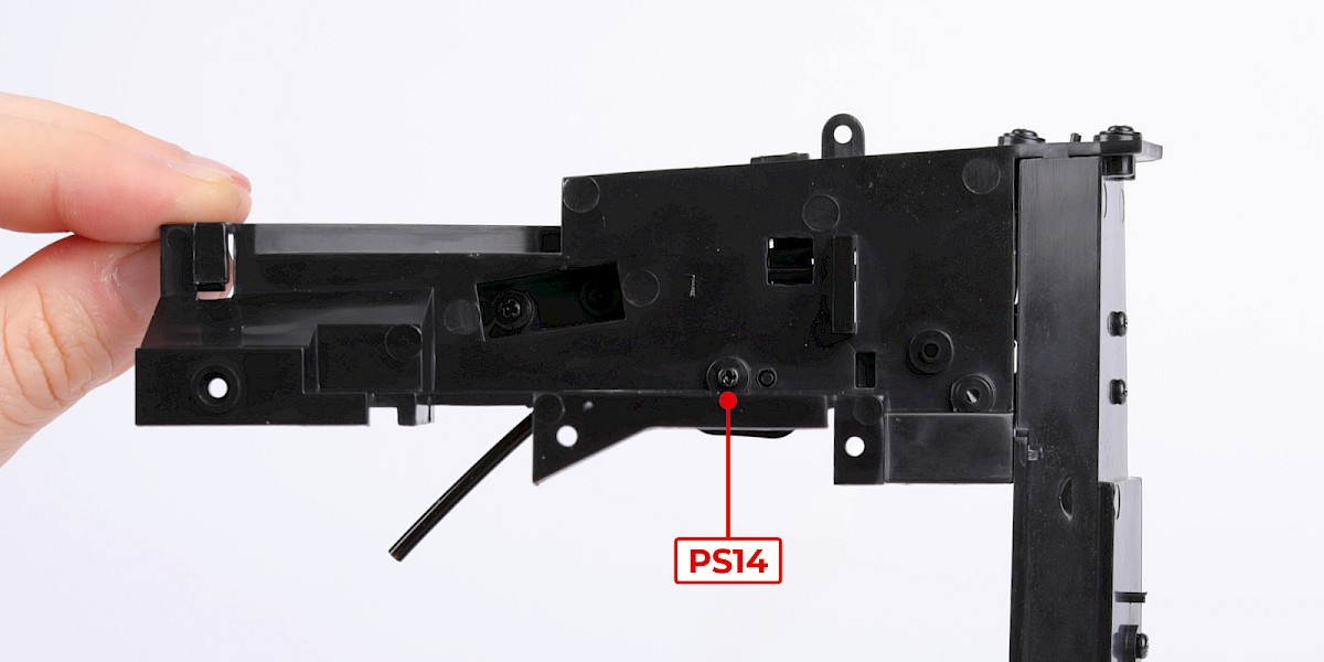
Step 7
Secure from underneath with 2x PS14.
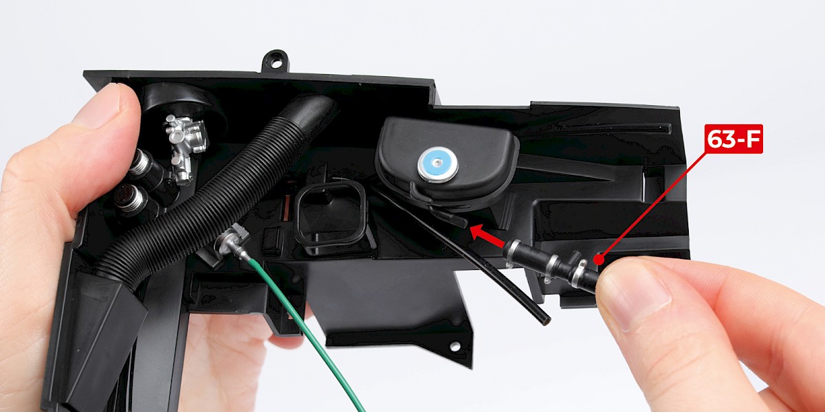
Step 8
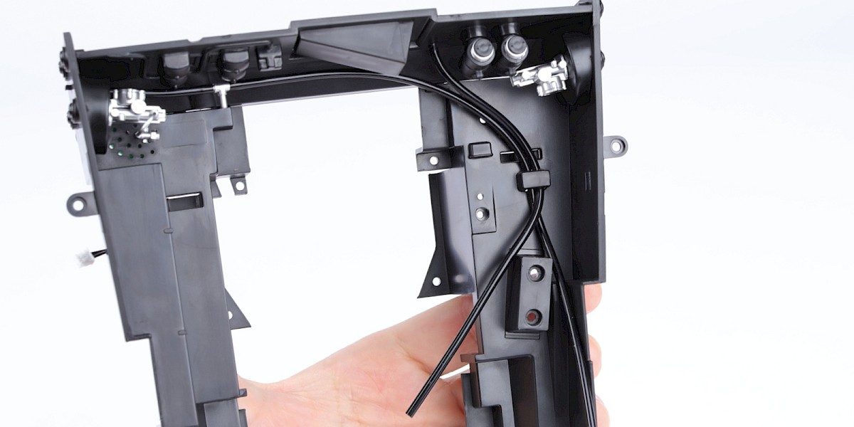
Fit the pipe (63-F) as shown.
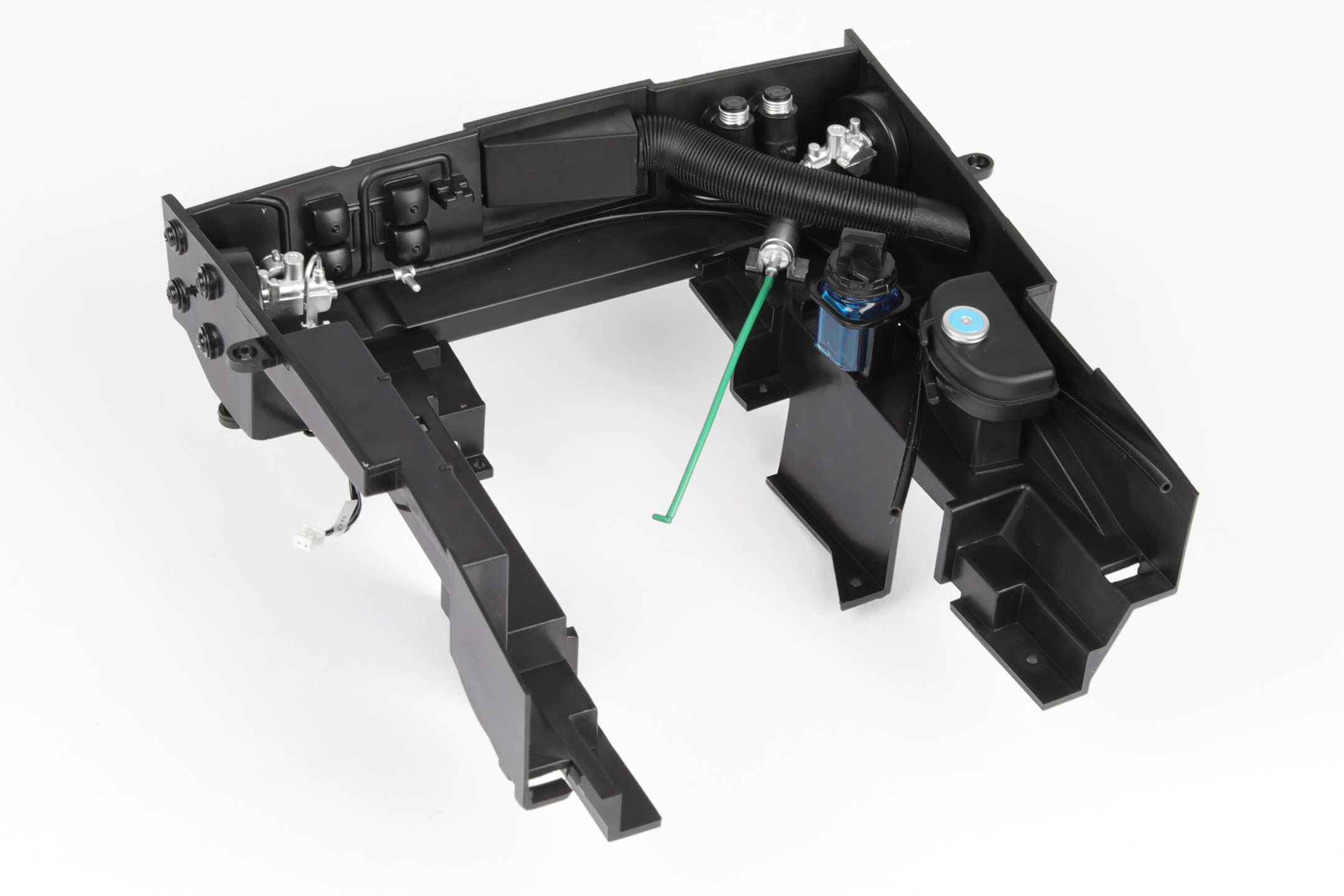
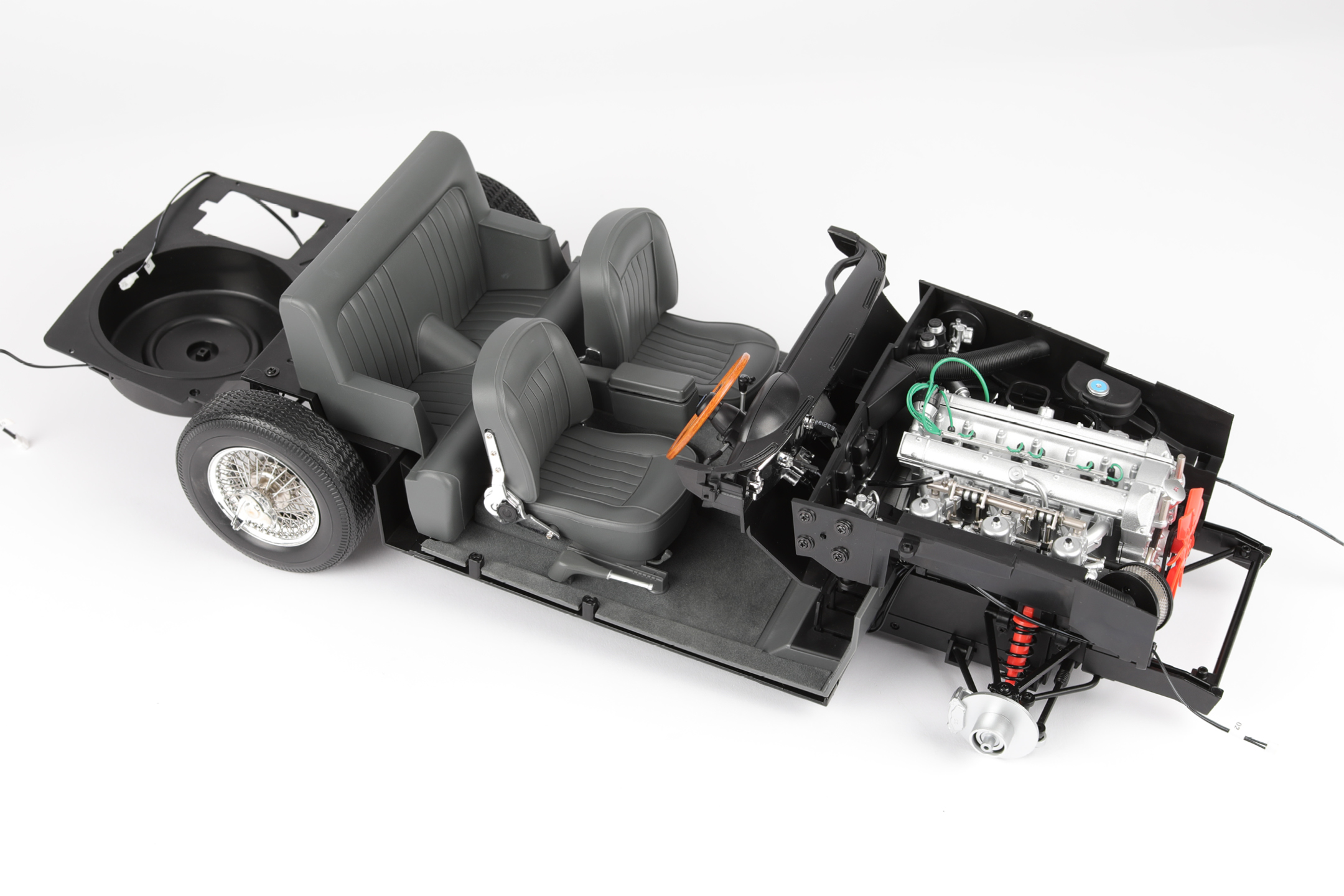
Step 9
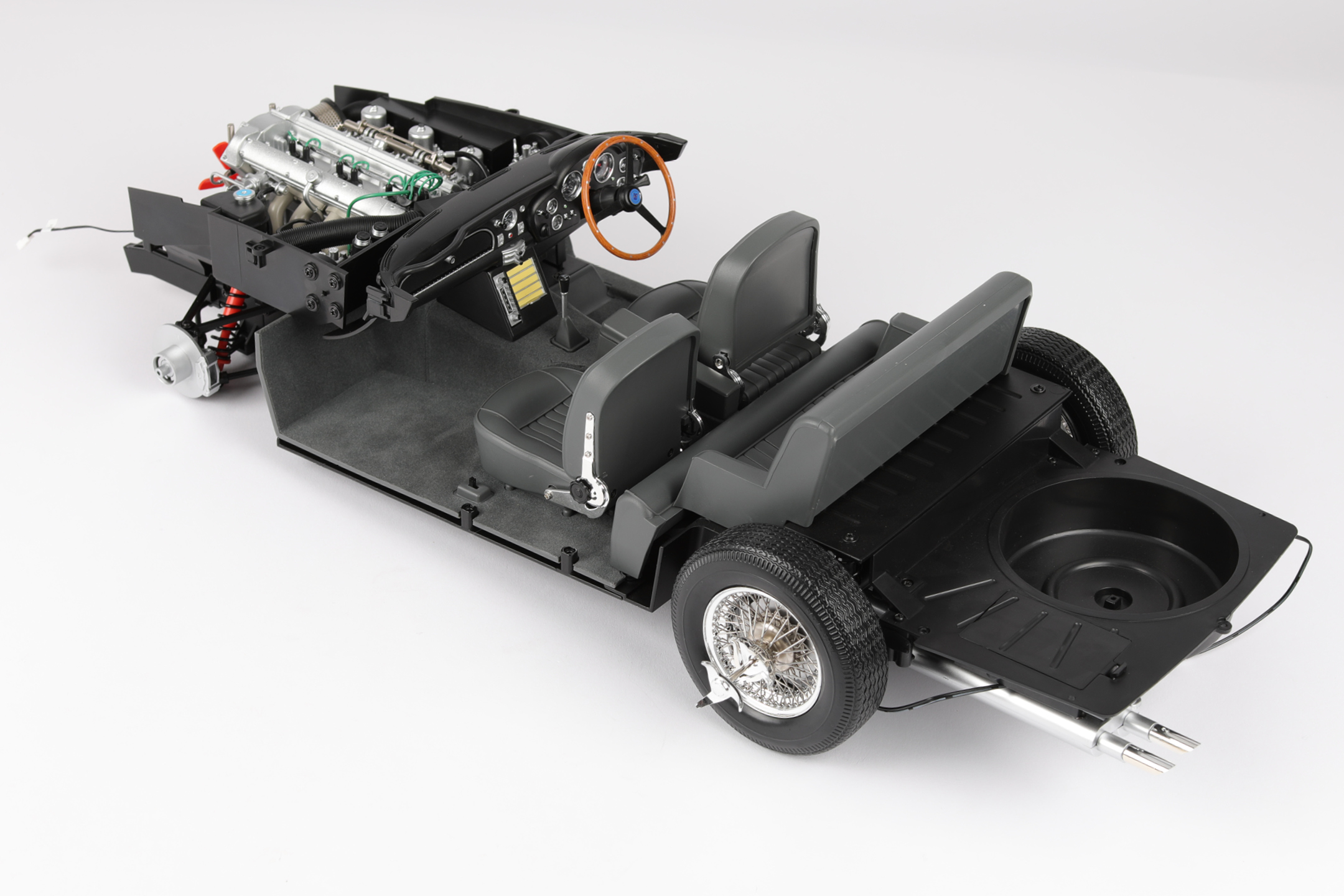
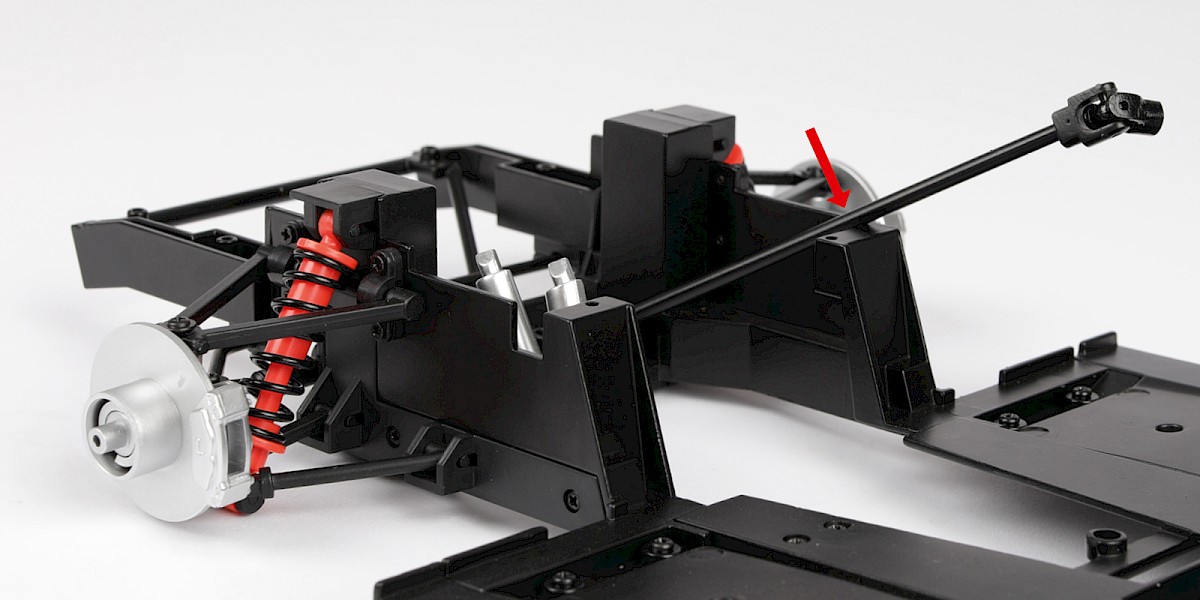
Place the chassis assembly (stage 042) on your work surface.
Position the steering column as shown by the red arrow.
Step 10
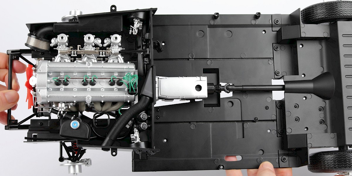
Fit the engine bay onto the assembly.
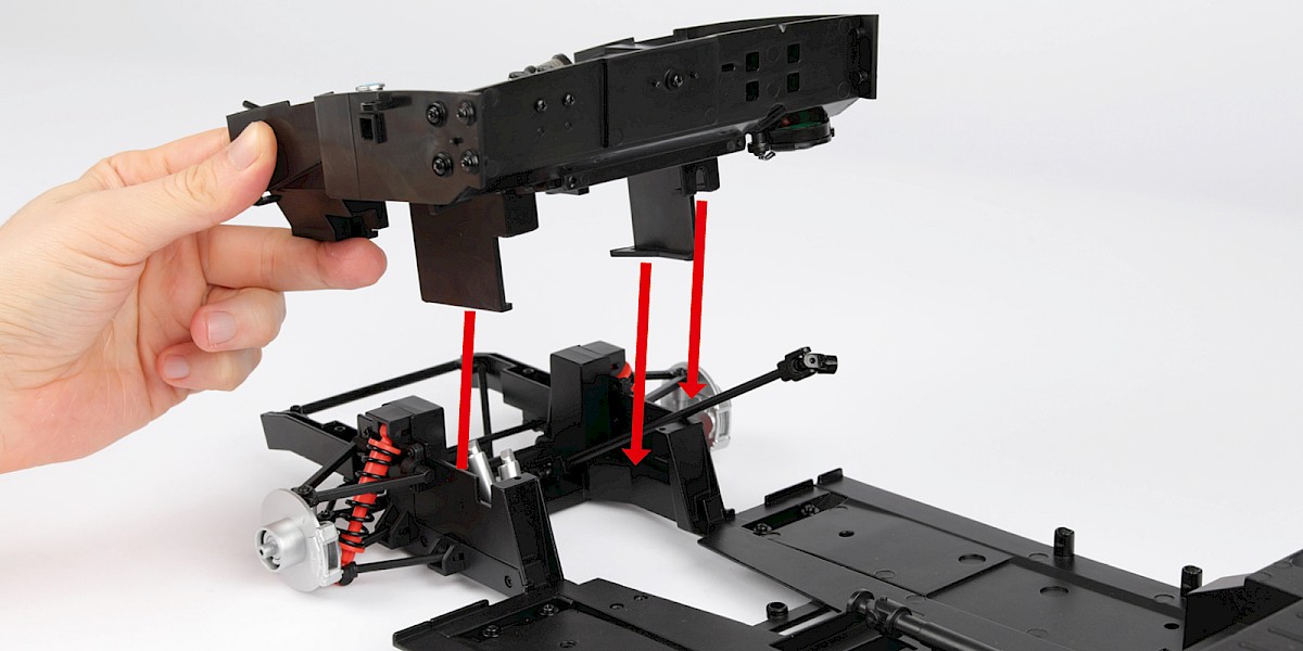
Step 11
Secure with 6x DS02.
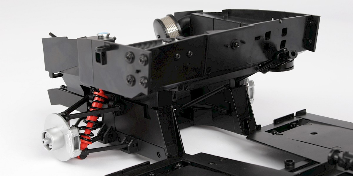
Step 12
Insert the engine (stage 019) through the opening as shown.
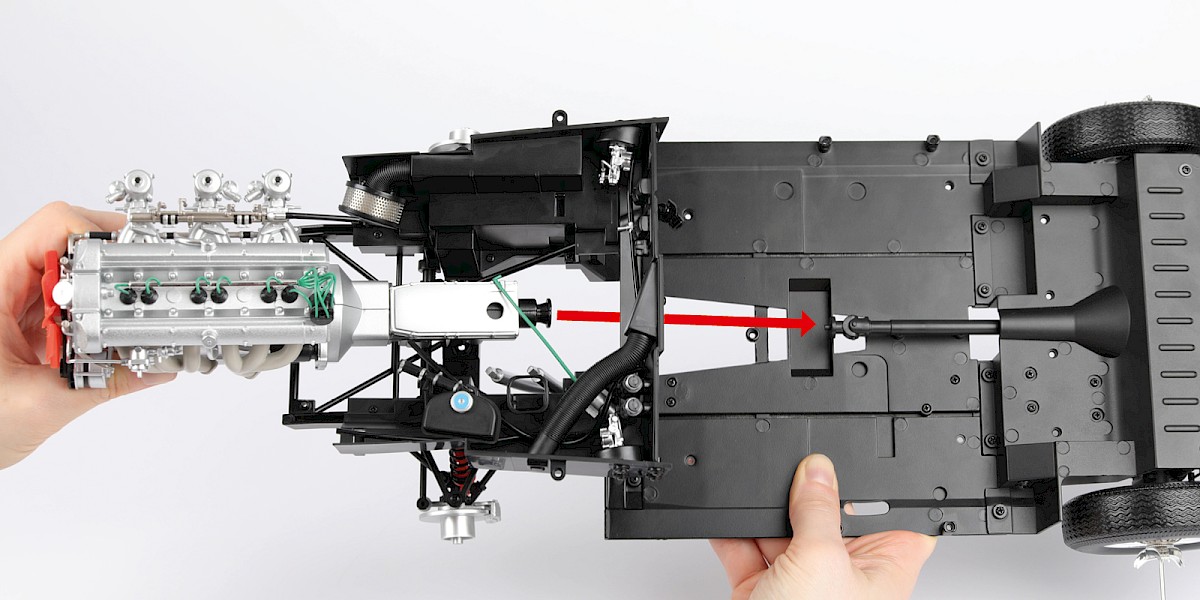
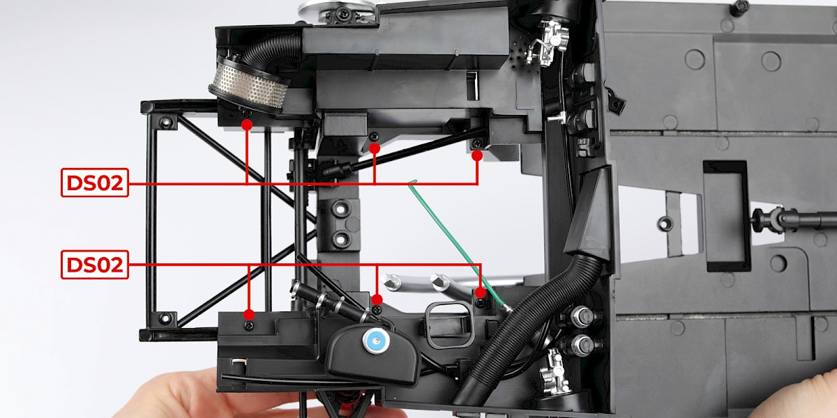
Step 13
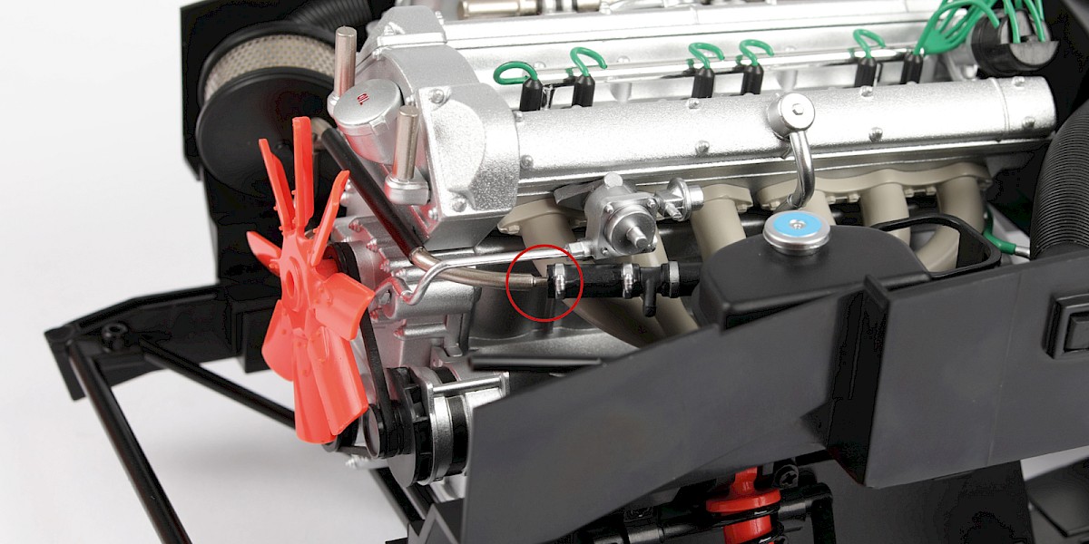
Fit the engine to the assembly, connecting the driveshaft to the gearbox.
Make sure to connect the pipes as shown in image (b).
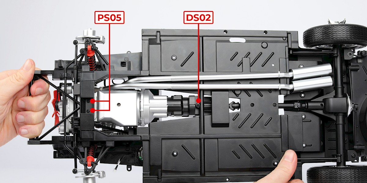
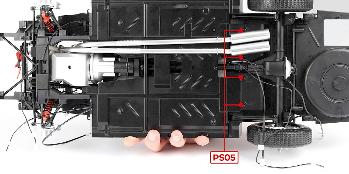
Step 14
Secure from underneath with 2x PS05 and 1x DS02.
Step 15
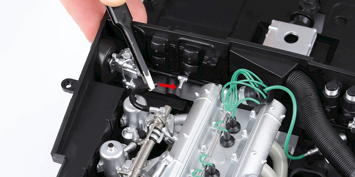
Fit the L-connector to the distributor.
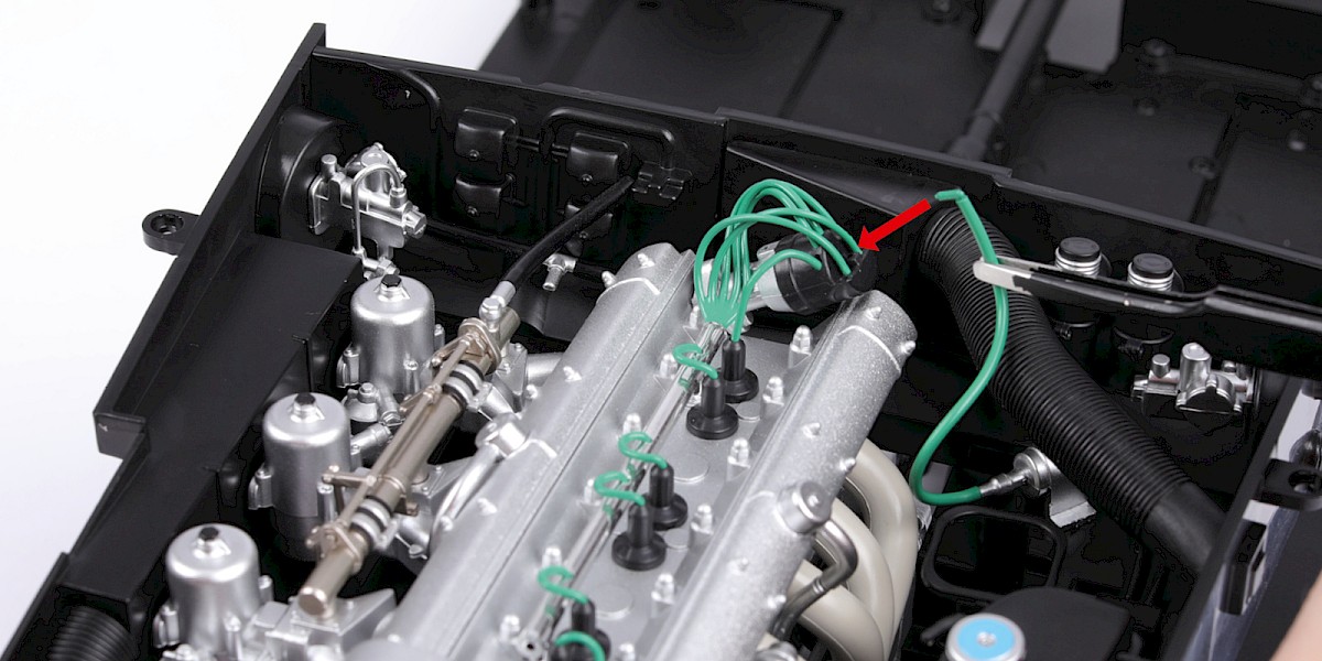
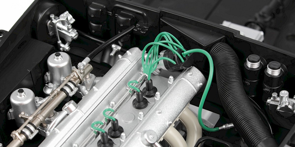
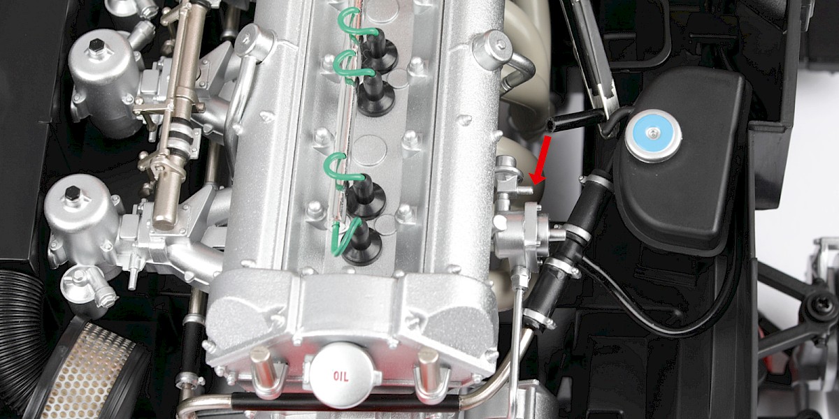
Step 16
Connect the long hose to the pipe.
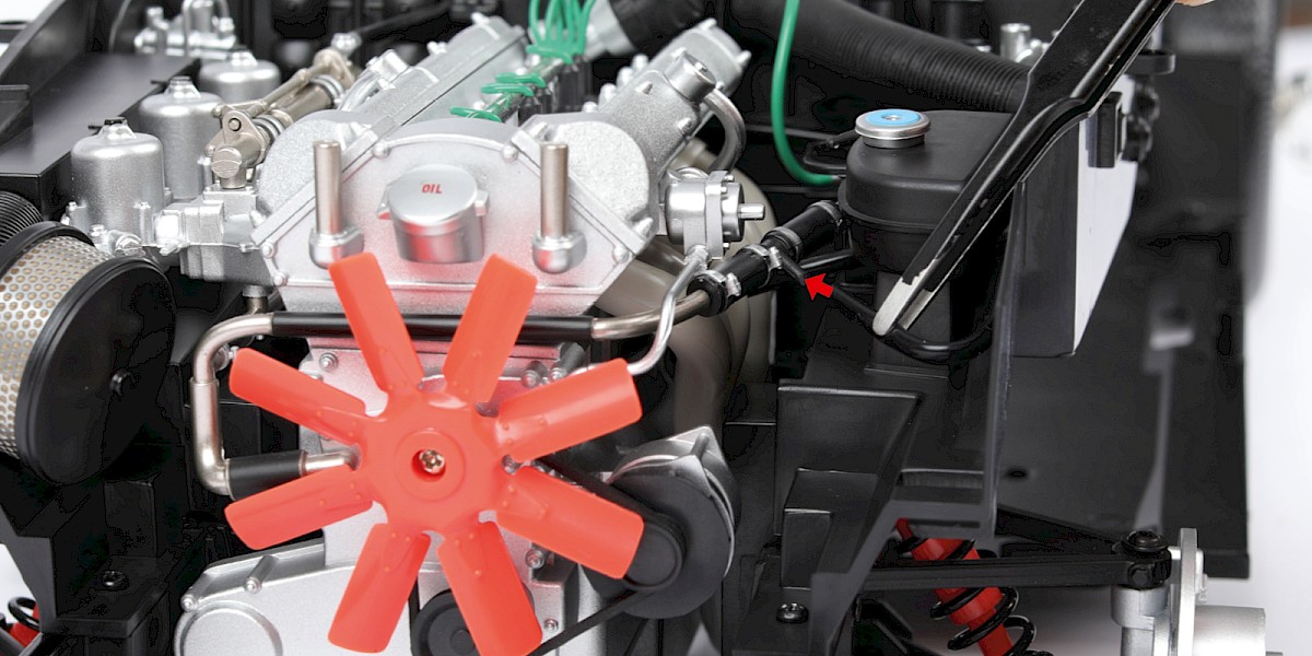
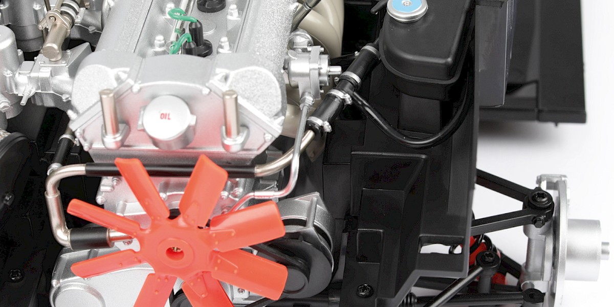
Step 17
Connect the short hose to the cooling water thermostat.
Step 18
Connect the fuel hose to the T-connector.
Step 19
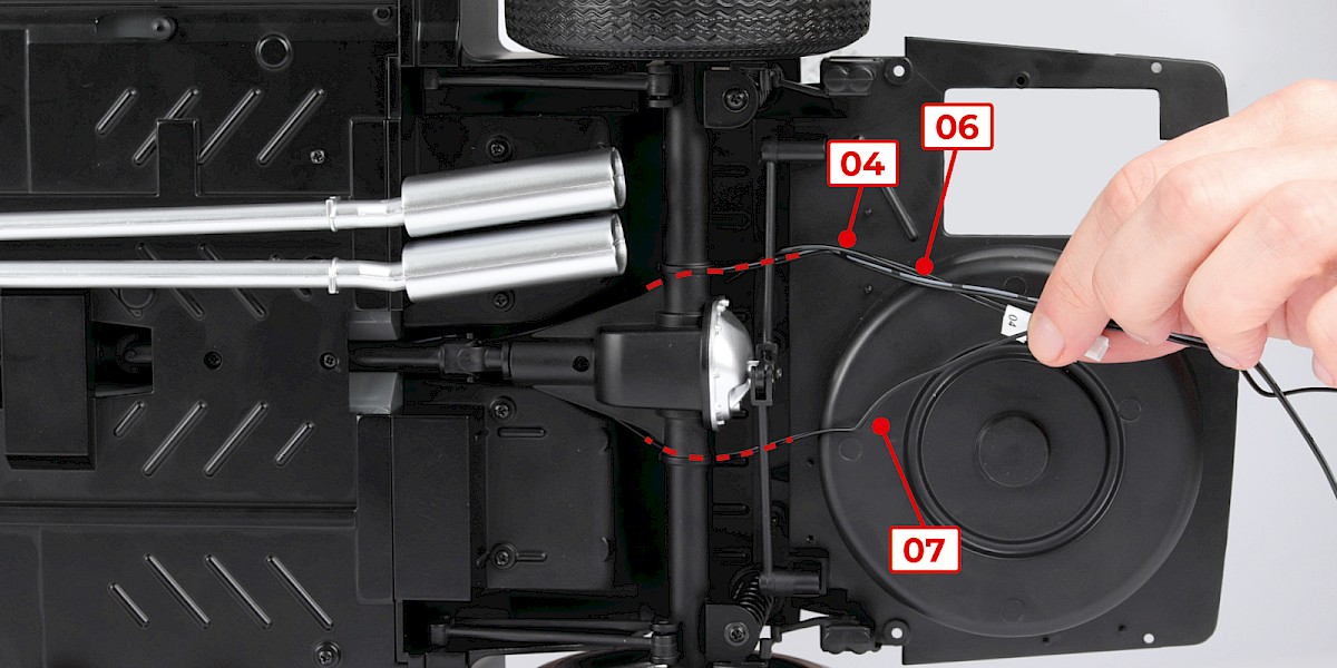
Retrieve the cockpit assembly (stage 057). Thread cable No. 04, cable No. 06 and cable No. 07 through the chassis as shown.
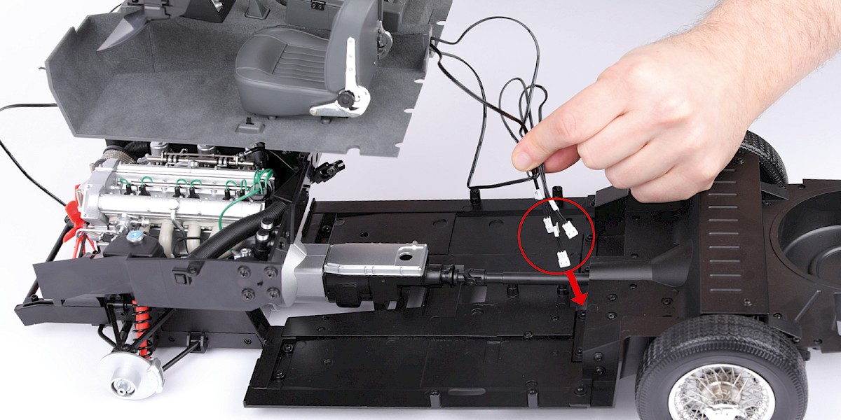
Step 20
Start to fit the cockpit assembly to the chassis.
Read steps 21 and 22. Both steps need to be performed as you fit the cockpit.
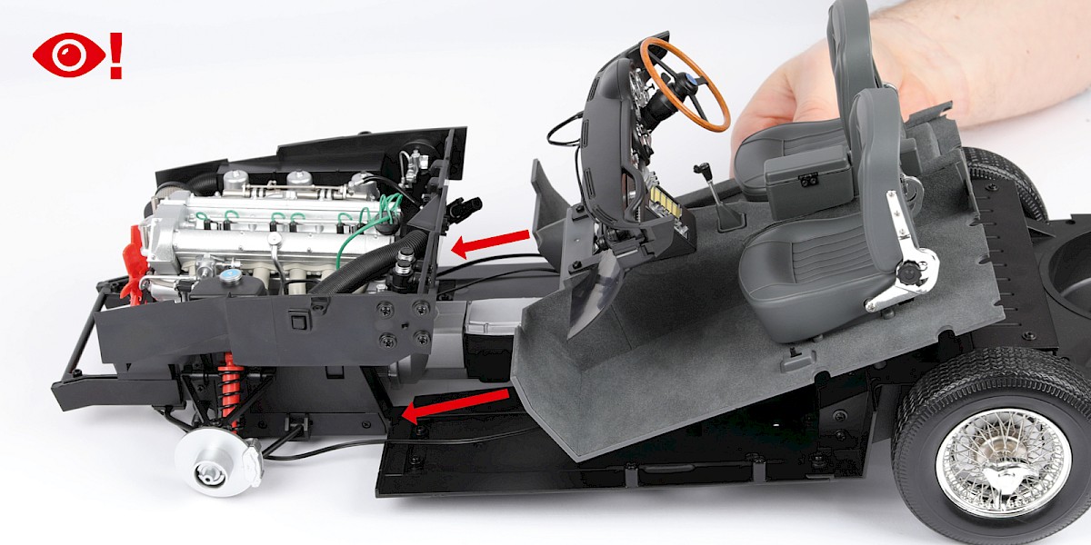
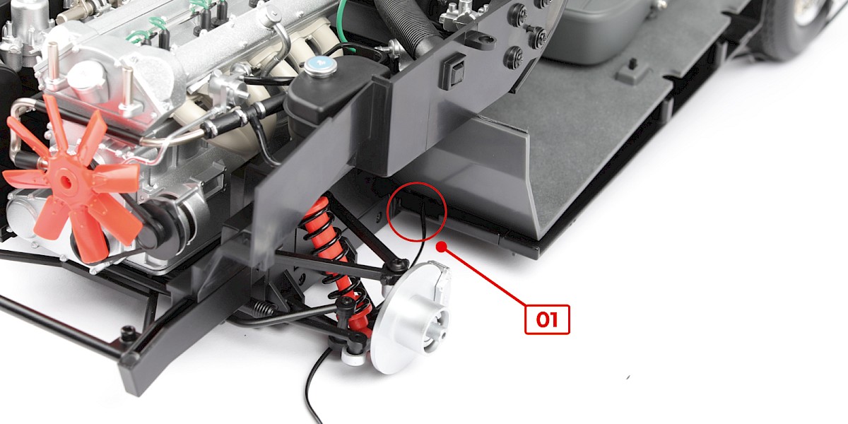
Step 21
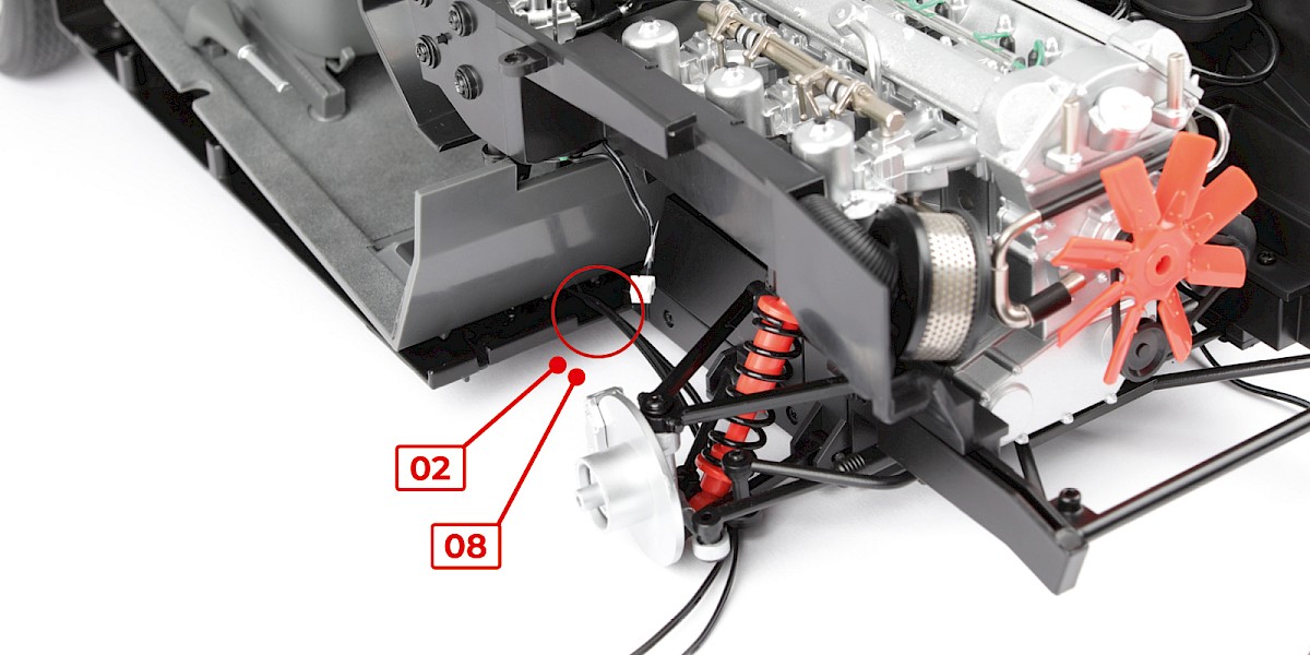
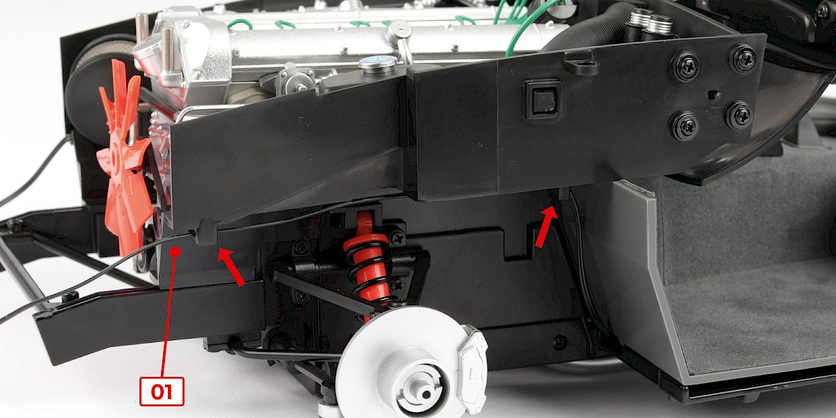
Position the cable No. 01 in the recess on the left-hand side, as shown by the red circle.
Step 22
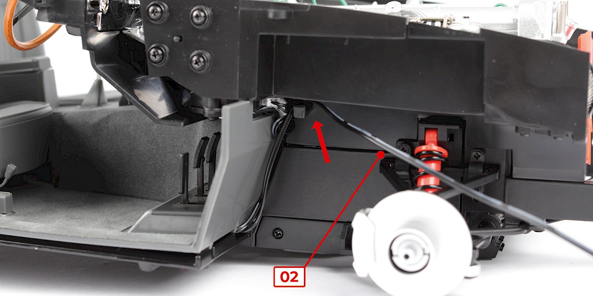
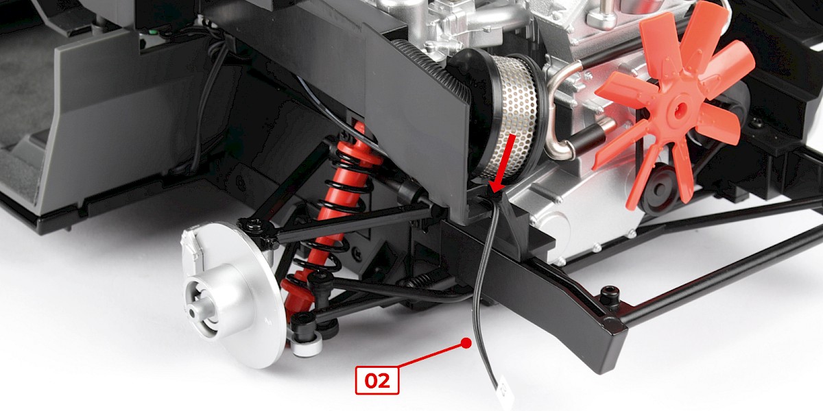
Position the cable No. 02 and cable No. 08 in the recess on the right-hand side, as shown by the red circle.
Step 23
Fit the steering link to the steering shaft.
Step 24
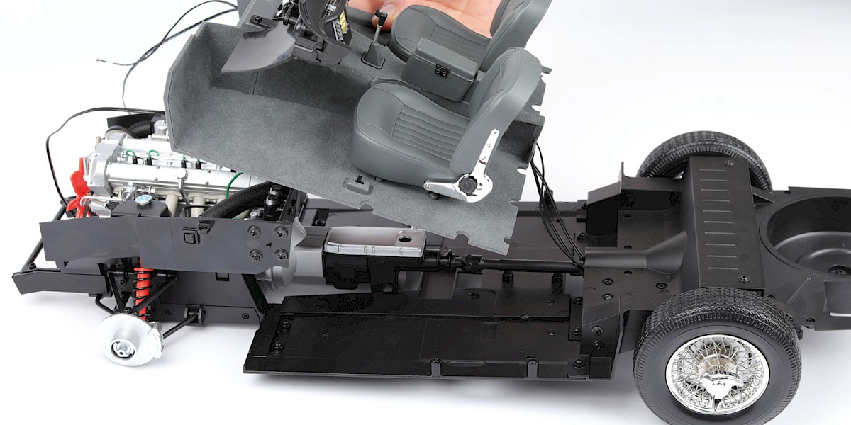
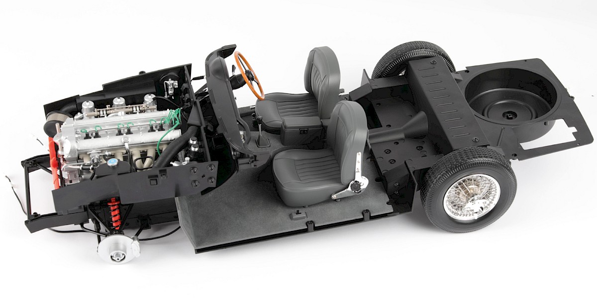
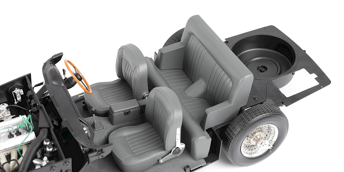
This image shows the cockpit fitted in place.
Step 25
Secure from underneath with 4x PS05.
Step 26
Fit the rear seat (stage 052) to the assembly.
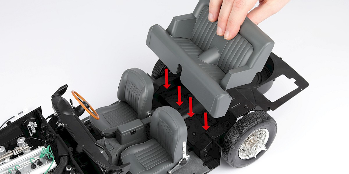
Step 27
Secure from underneath with 4x PS05.
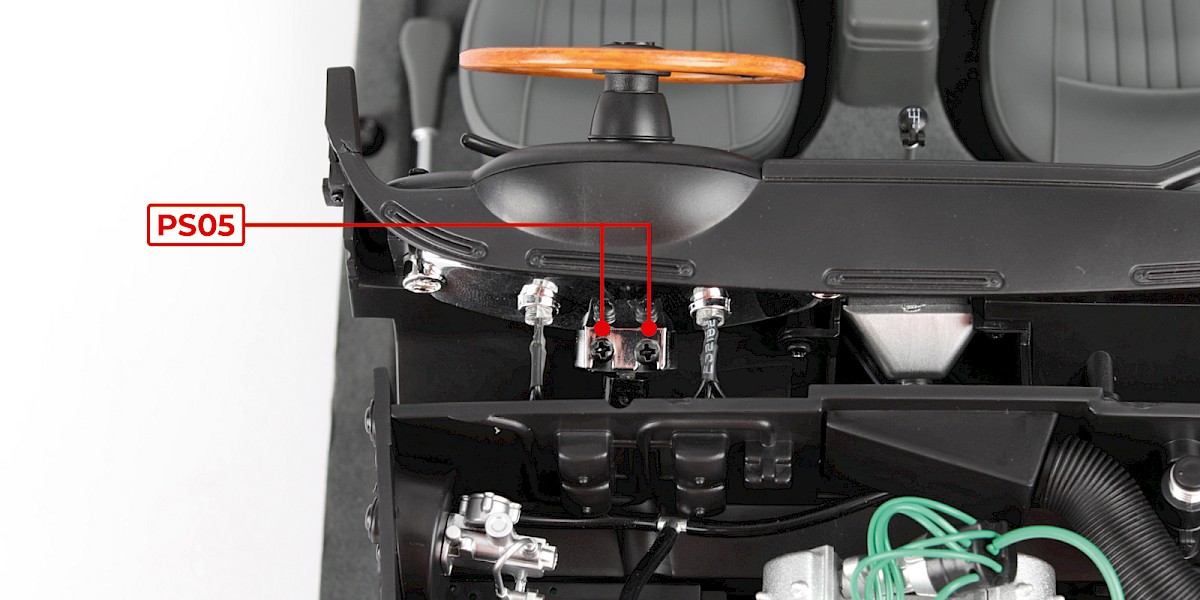
Step 28
Secure the dial housing with 2x PS05.
Secure the steering shaft with 1x DS20.
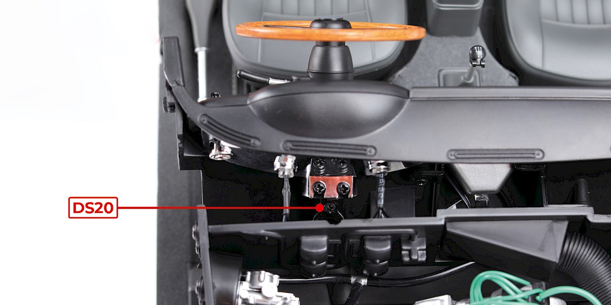
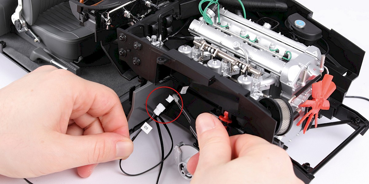
Step 29
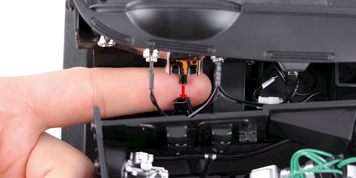
Connect the two cables labelled "08".
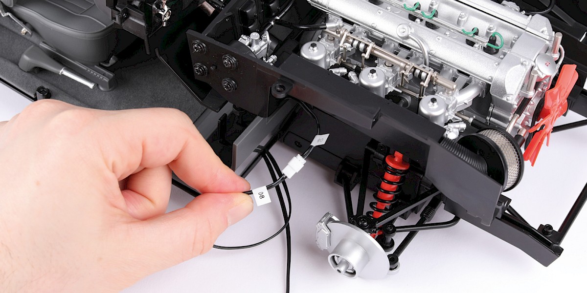
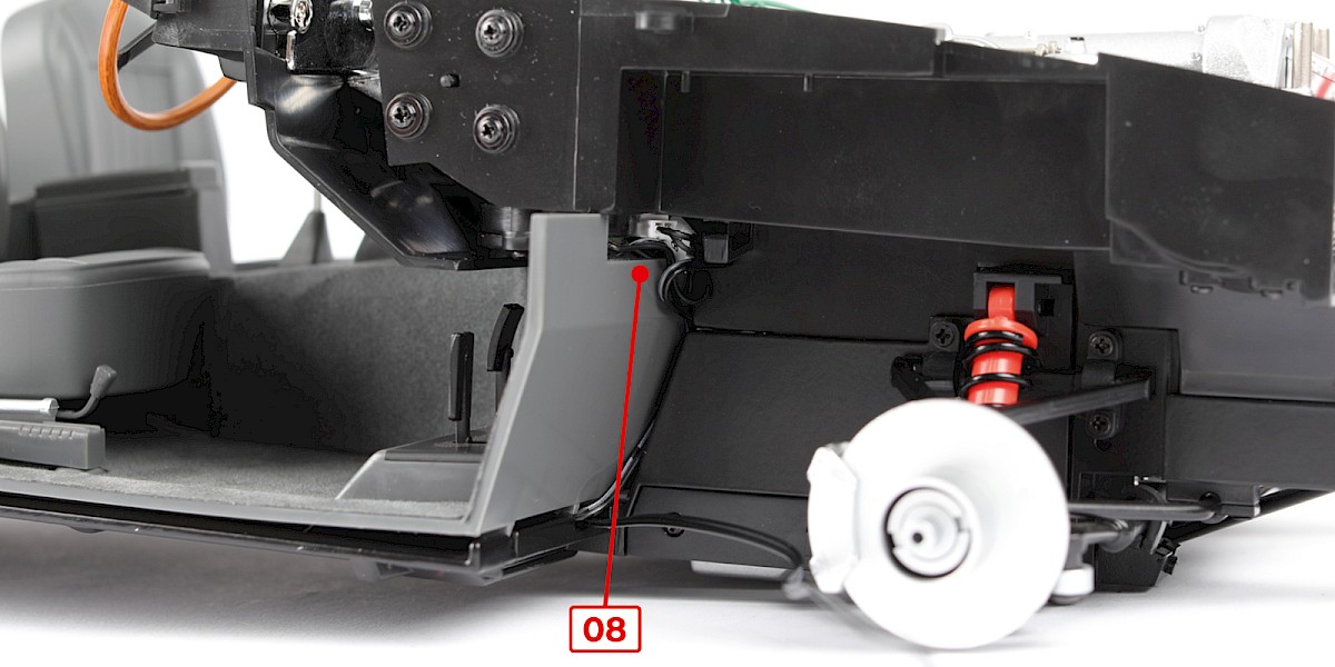
Step 30
Tuck the cable No. 08 behind the firewall.
Step 31
Fit the cable No. 02 into the hooks as shown.
Step 32
Fit the cable No. 01 into the hooks as shown.
Step 33
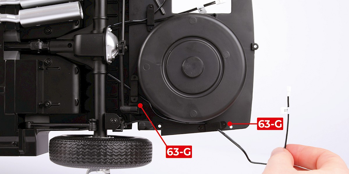
Thread the cable No. 04, cable No. 06 and cable No. 07 under the rear axle as shown.
Step 34
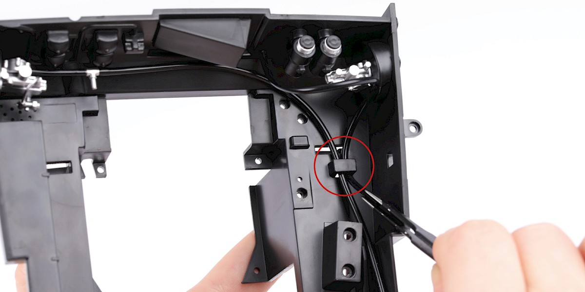
Secure cable No. 04 and cable No. 06 with a cable fastener (63-G).
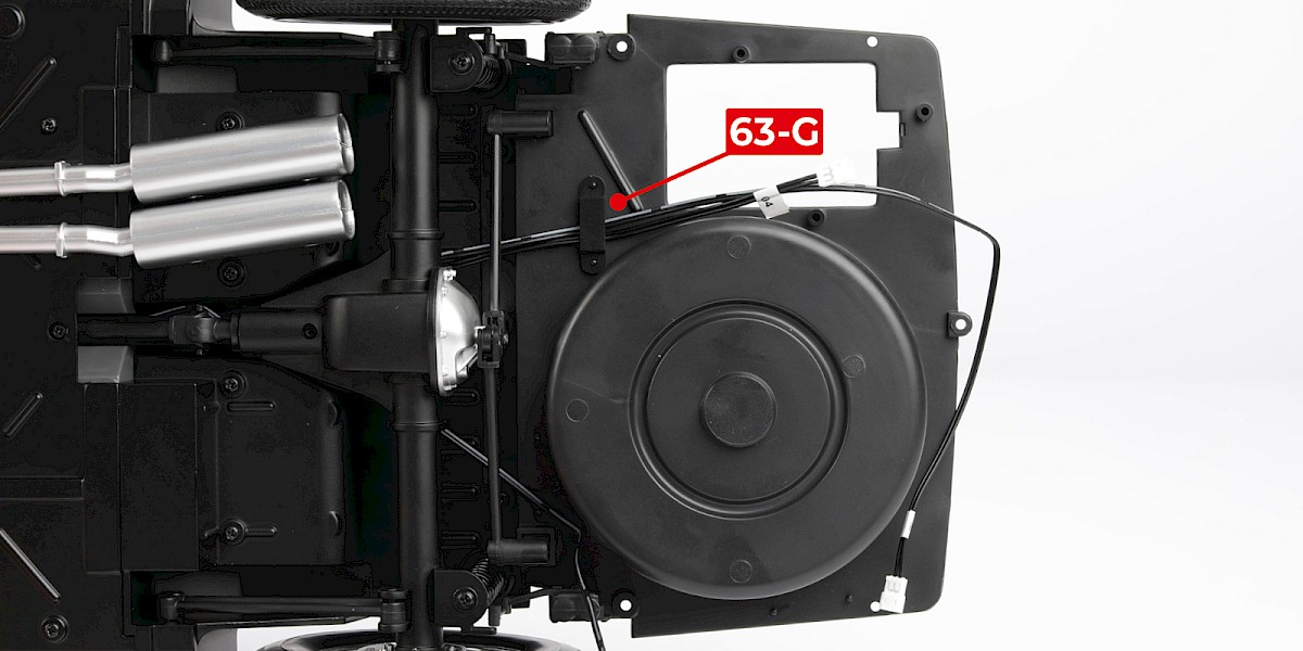
Step 35
Secure cable No. 07 with two cable fasteners (63-G) as shown.
STAGE COMPLETE
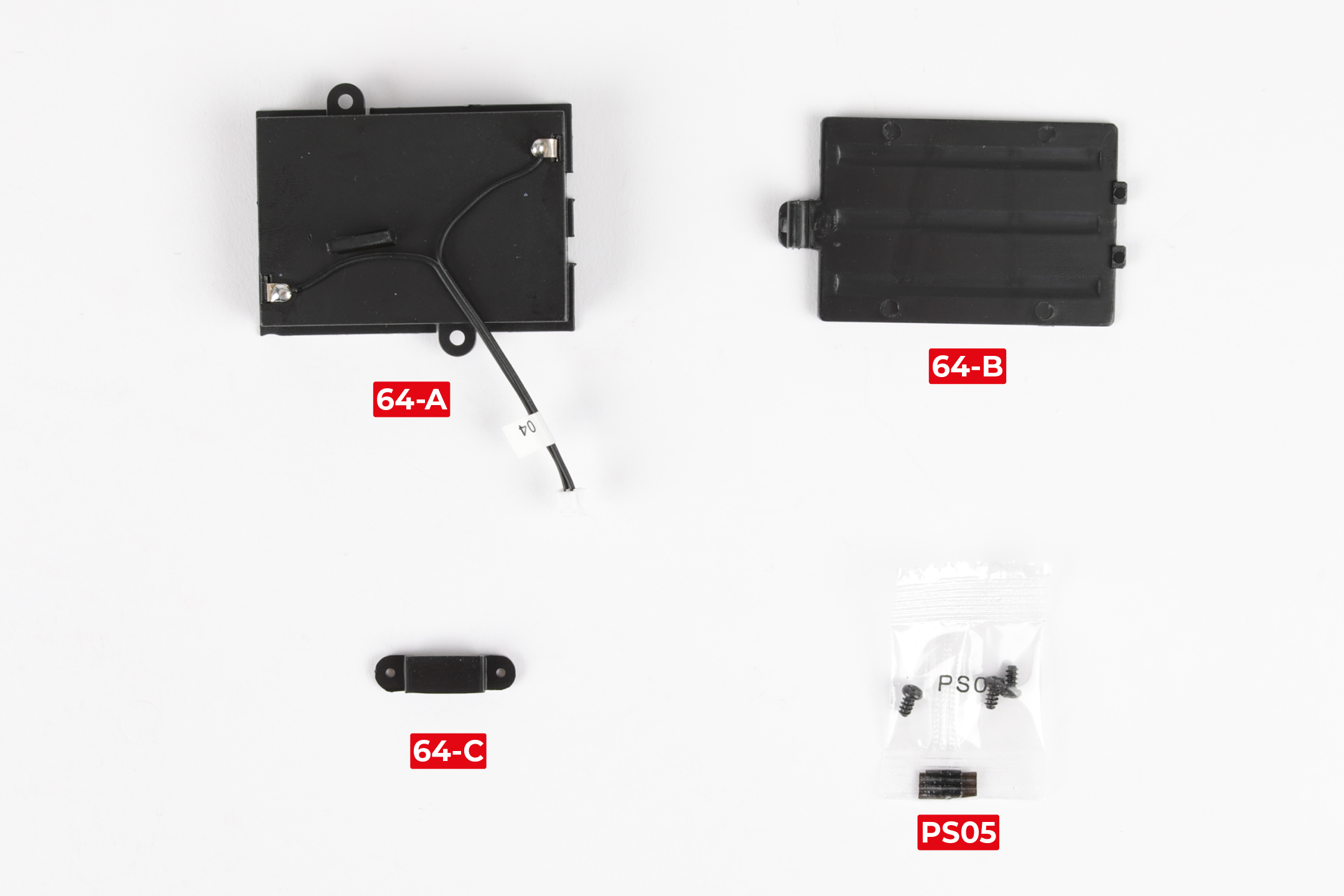
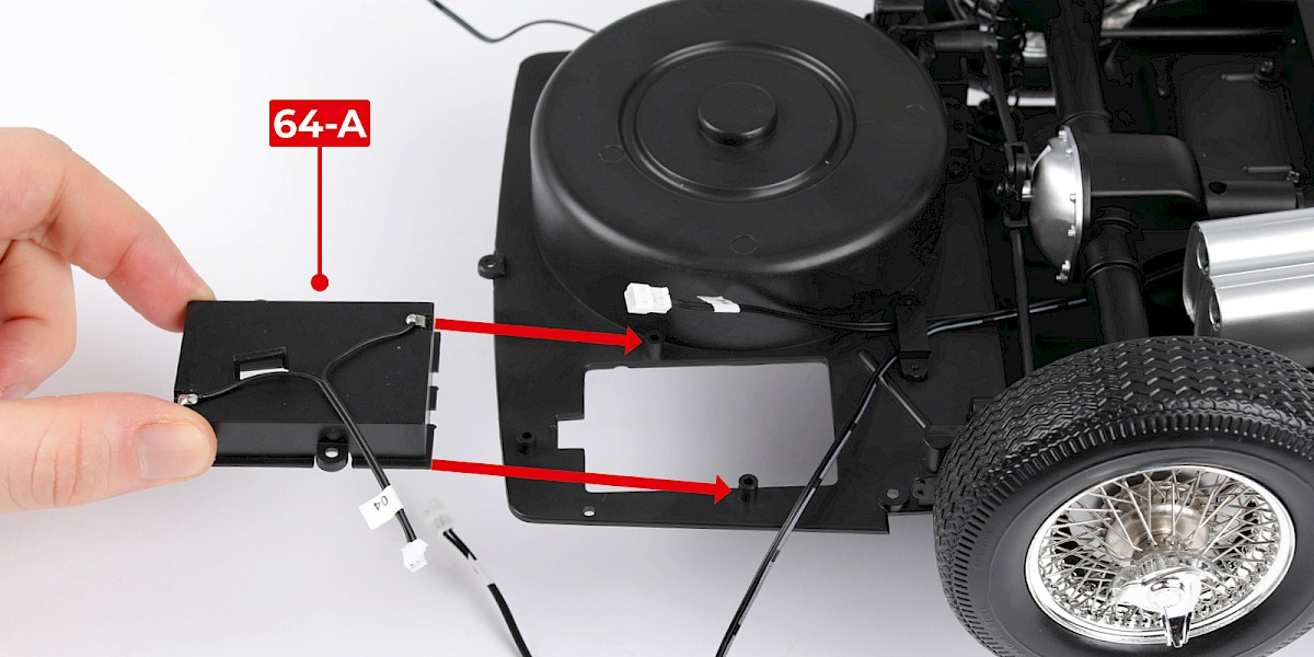
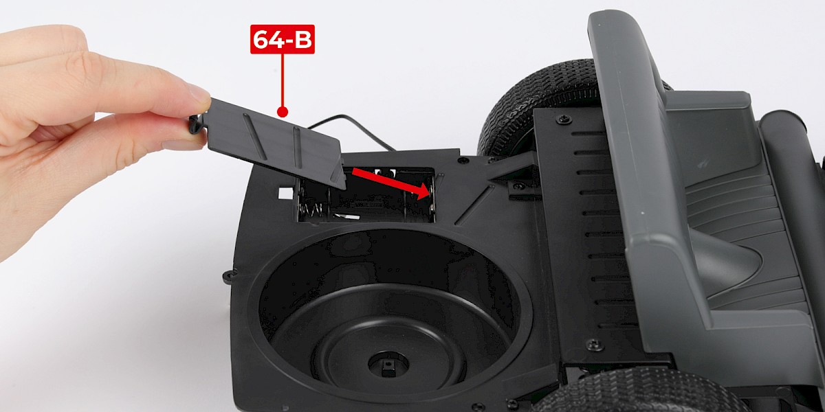
PARTS LIST
| 64-A Battery compartment |
| 64-B Battery compartment cover |
| 64-C Cable fastener* |
| 3x PS05 screws |
* The cable fastener is a spare.
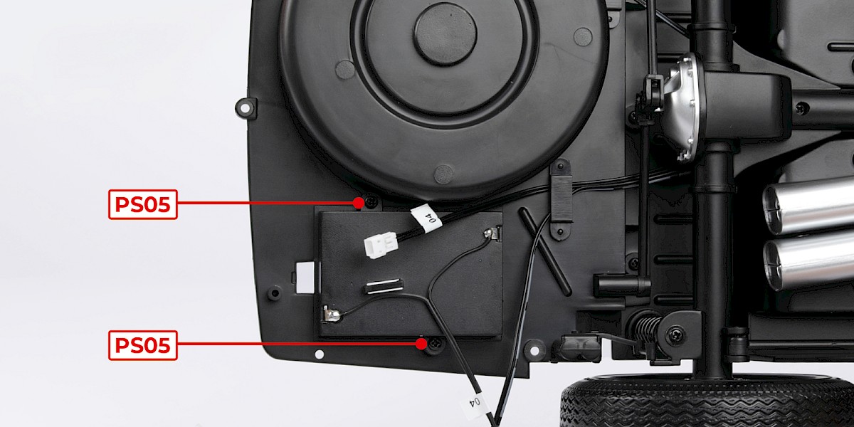
Step 1
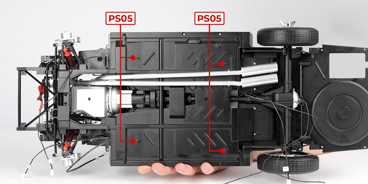
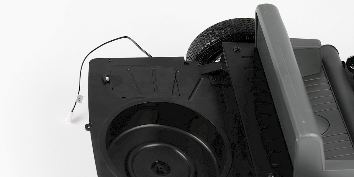
Fit the battery compartment (64-A) to the chassis assembly (stage 063).
Secure with 2x PS05.
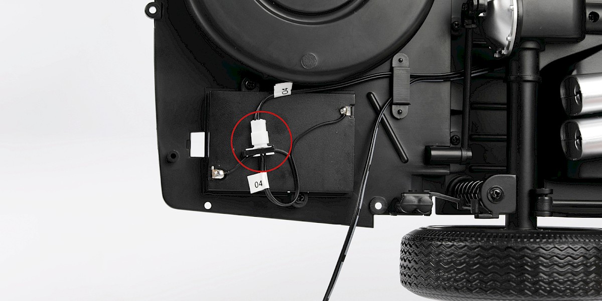
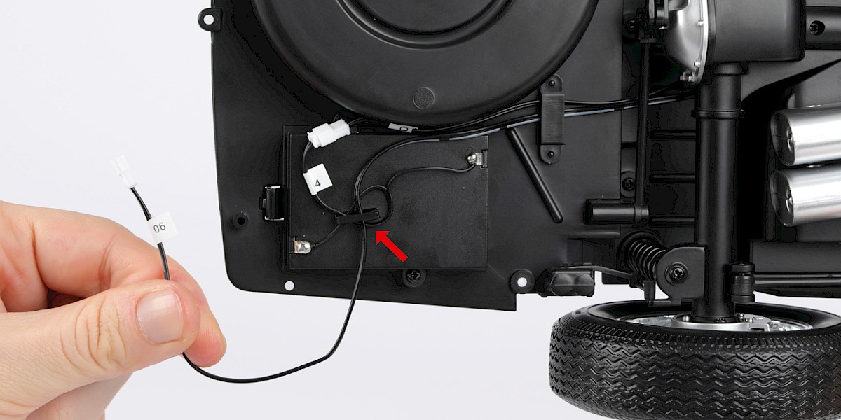
Step 2
Connect the cables labelled "04".
Tuck cable No. 04 and cable No. 06 under the hook.
Step 3
Fit the battery compartment cover (64-B) onto the battery compartment.
STAGE COMPLETE
PARTS LIST
| 65-A Front housing |
| 65-B Rear housing |
| 65-C Screen |
| 65-D Spring x2 |
| 65-E Clamp x2 |
| 5x PS05 screws |
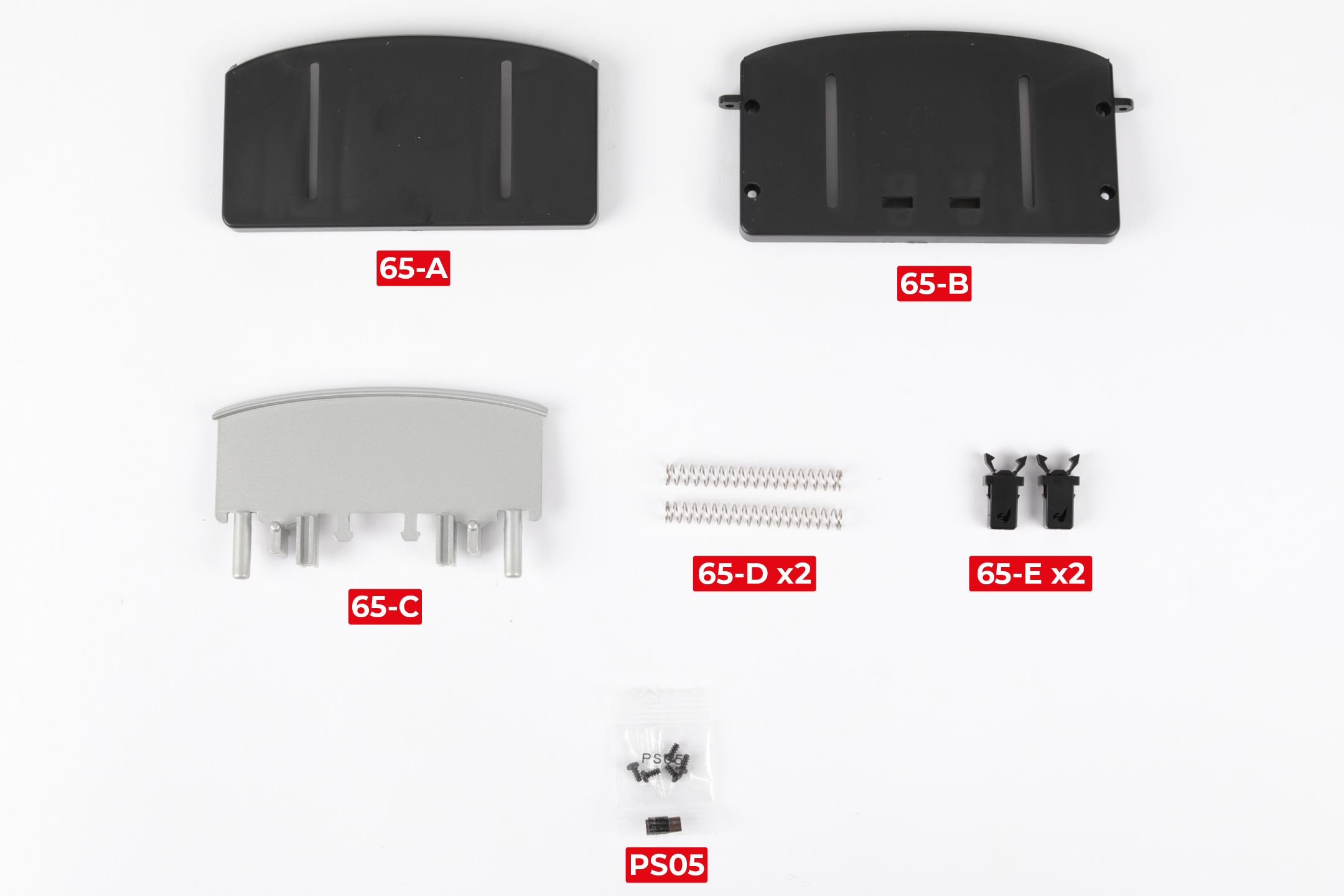
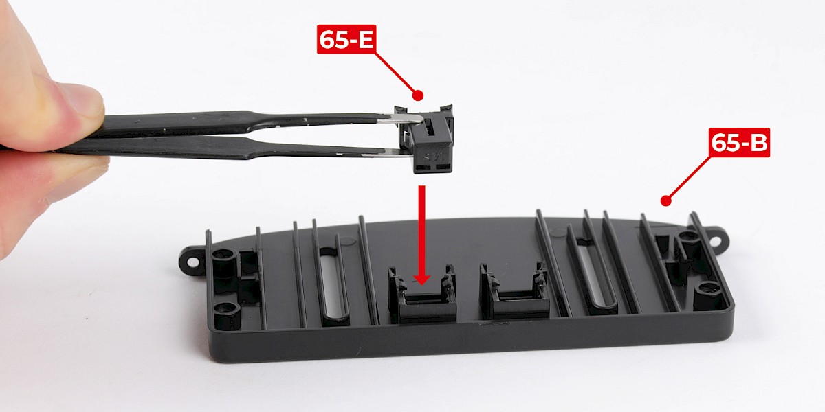
Step 1
Fit a clamp (65-E) to the rear housing (65-B).
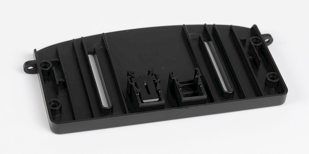
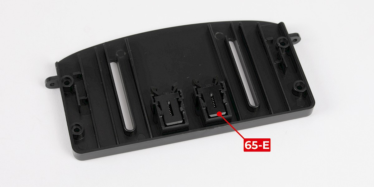
Step 2
Fit the second clamp (65-E) in the same way.
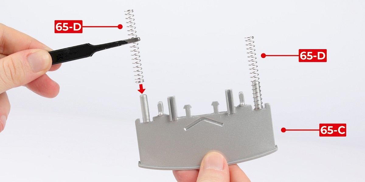
Step 3
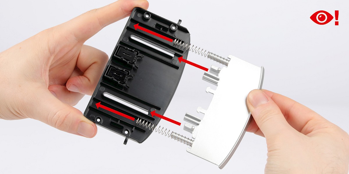
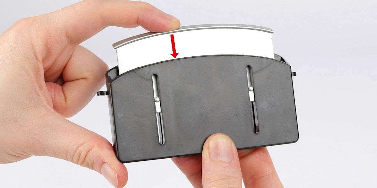
Fit the springs (65-D) to the screen (65-C).
Step 4
Fit the assembly into the rear housing.
Check the parts fit together in the orientation shown.
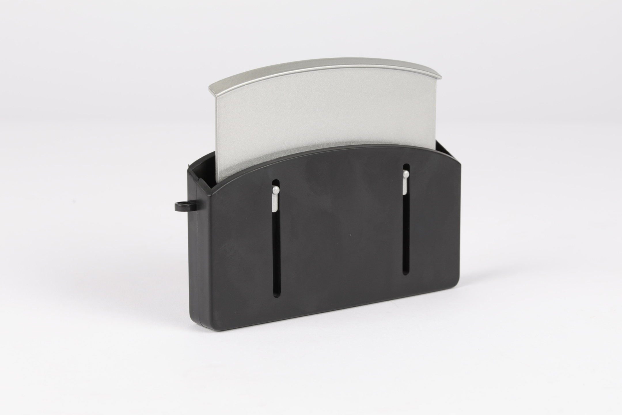
Step 5
Fit the front housing (65-A) onto the assembly.
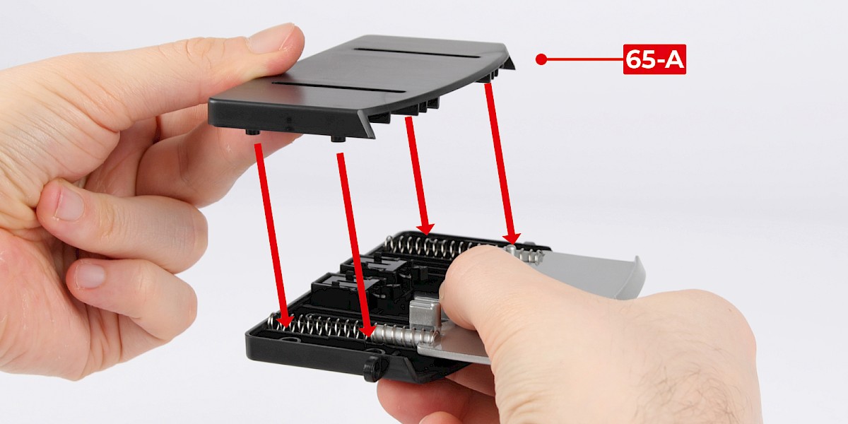
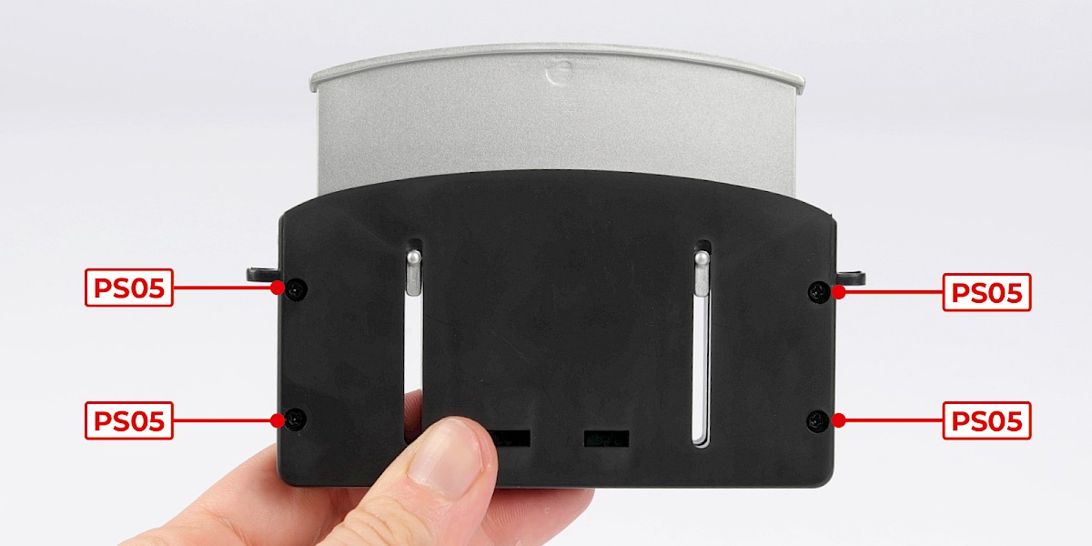
Step 6
Secure with 4x PS05.
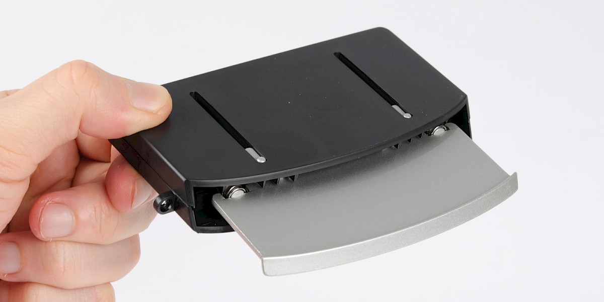
Step 7
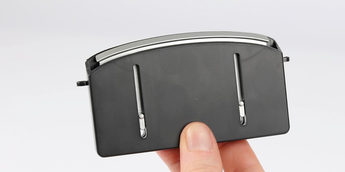
Test the mechanism by pressing the screen into the housing.
STAGE COMPLETE
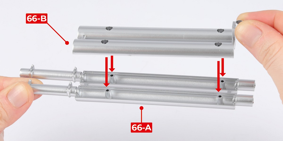
PARTS LIST
| 66-A Exhaust pipes (top) |
| 66-B Exhaust pipes (bottom) |
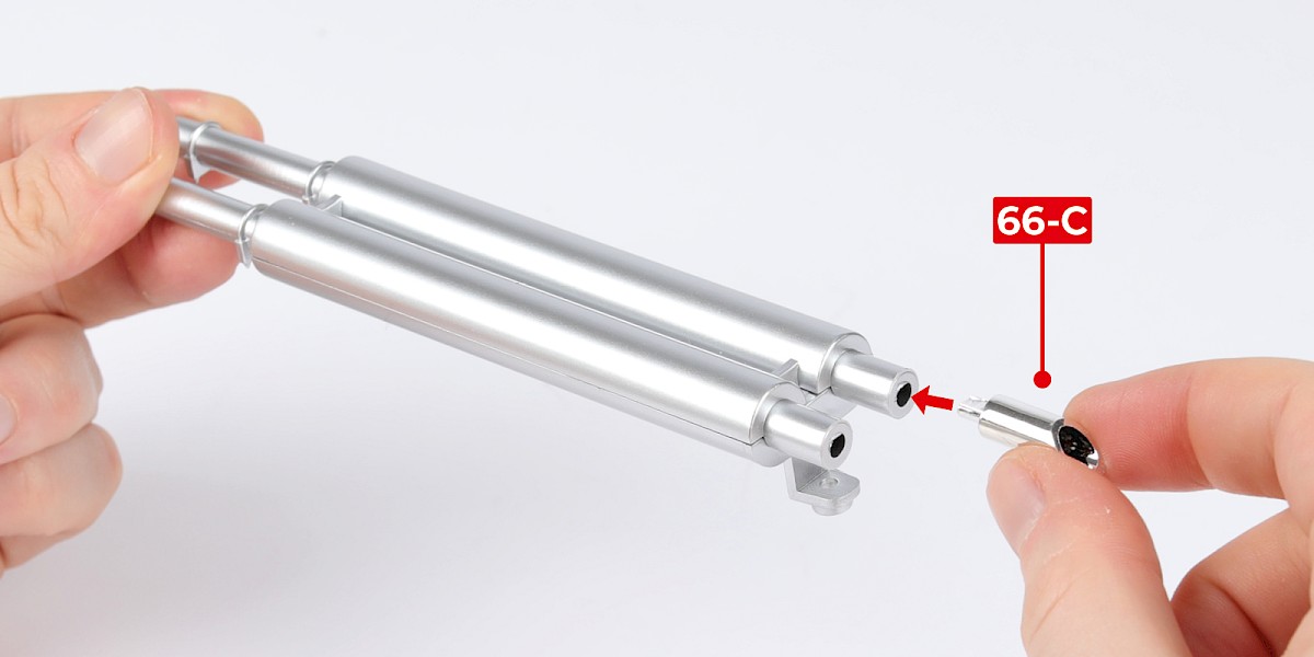
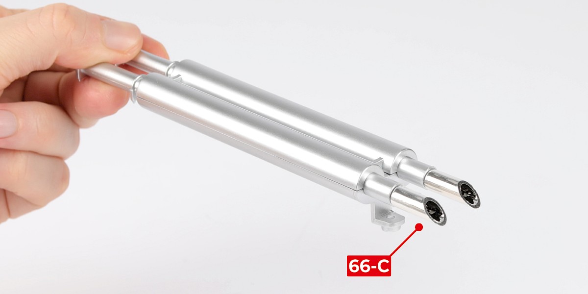
| 66-C Exhaust tailpipe x2 |
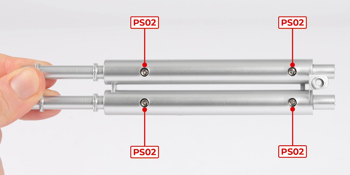
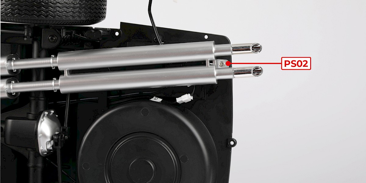
| 6x PS02 screws |
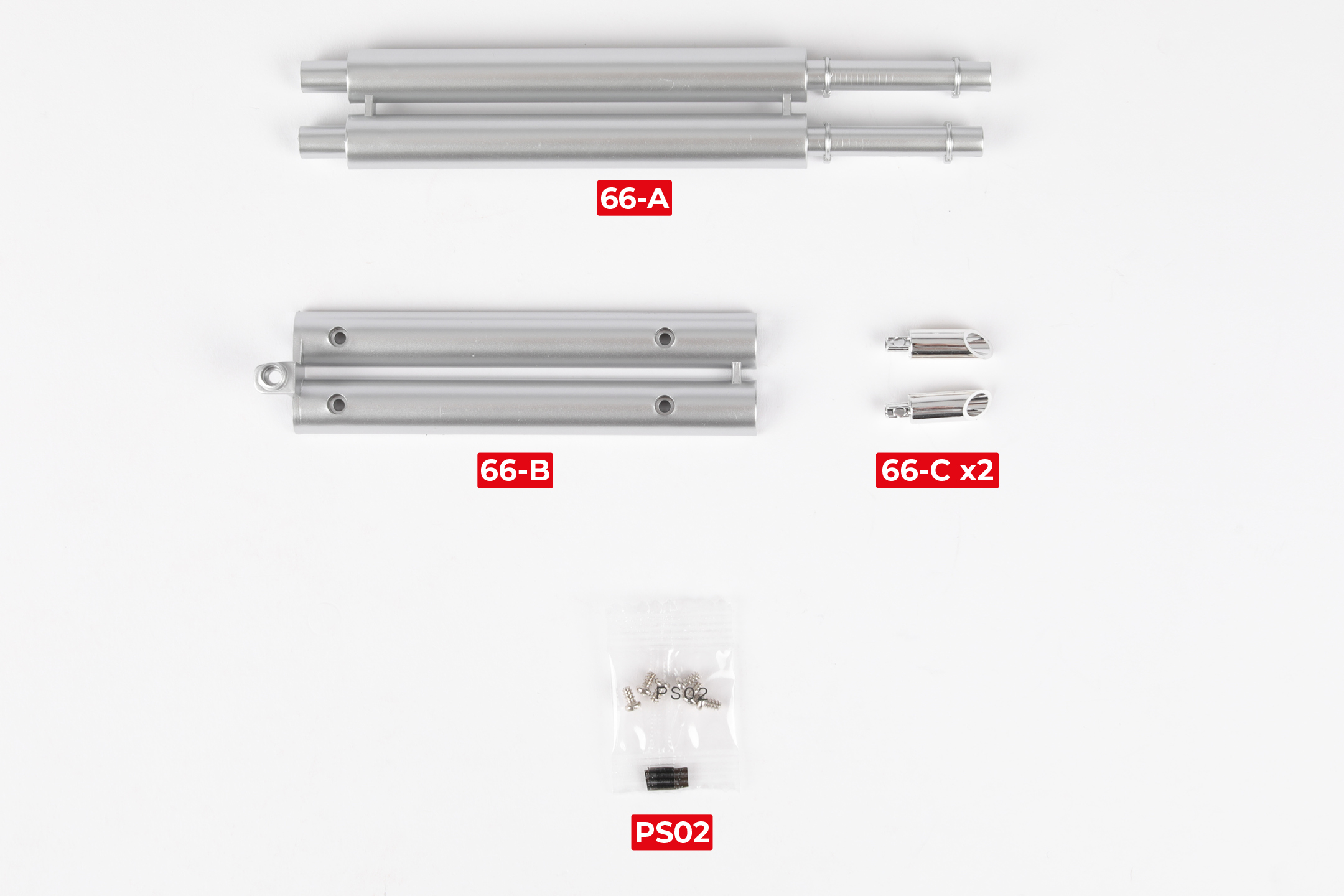
Step 1
Fit the top of the exhaust pipes (66-B) to the bottom of the exhaust pipes (66-A).
Secure them together using 4xPS02.
Step 2
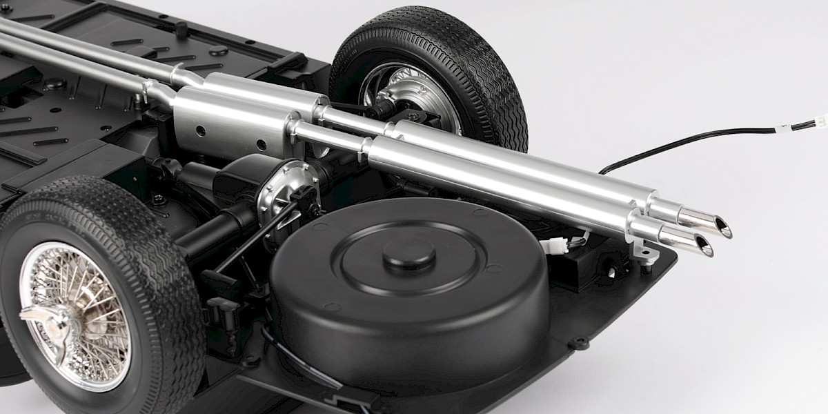
Fit the two tailpipes (66-C) to the assembly.
Step 3
Fit the assembly to the chassis (stage 064).
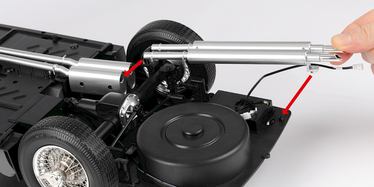
Step 4
Secure with 1x PS02.
STAGE COMPLETE