Pack 9
BUILD INSTRUCTIONS
Advice from the experts
Spare screws are included with each part. Occasionally, you may be instructed to keep spare or unused screws for a later stage. Keep these spares in a safe place and label them correctly.
Please make sure you don’t mix up the screws. They look quite similar, but the threads do vary slightly. Using the wrong screws may damage the parts. Only use the correct size screwdriver that fits the screw head firmly.
When securing parts together using multiple screws, fit each screw loosely to ensure all the parts are correctly aligned before gently tightening them firmly, but not overtight, in the order in which you placed them.
The screwdriver can be magnetized by stroking it with a magnet (fridge magnet, etc.) enabling it to hold the screws and make assembly easier.
If a screw is tight going into a metal part, do not force it as you may shear the head off. Remove it and put a tiny smear of Vaseline, soap or light oil on the thread. That will lubricate it and make it easier to tighten.
Some parts will require a little glue for assembly. Please apply glue sparingly and use a cocktail stick so that you don’t use too much nor apply the glue too heavily. We recommend superglue gel or Extra Thin Liquid modeling glue. Where possible, parts should be test-fitted in place before gluing.
Make sure you have good ventilation when using adhesives and to replace caps firmly.
Use a magnet to help find screws that have fallen on the floor.
Use masking tape to hold parts temporarily in place.
Cut parts from a sprue (framework) with side cutters or a craft knife. Side cutters tend to be easiest.
During the course of this build, you will receive many pieces that you will assemble immediately – following the instructions in the corresponding stage – and other pieces that you should store safely to one side, for use in future assembly stages.
Always protect the paint finish on components by placing a cutting mat, sheet of white paper or soft cloth on your work surface.
When plugging cables in, ensure the power is switched off. Tweezers can be used to fit the PVC cables by gripping carefully around 5mm from the end of the cable. If a cable needs to be removed from a socket, do not pull on the cable as this could damage the connection. Grip the plug with tweezers to remove it.
Left and Right! When building your AH-64 Apache, the left- or right-hand side refers to that side as if you are sitting in the cockpit.
![]() When you see this symbol, pay attention to the instruction text in bold and check the orientation of the parts in the image as this will be particularly important for assembly in later stages.
When you see this symbol, pay attention to the instruction text in bold and check the orientation of the parts in the image as this will be particularly important for assembly in later stages.
WARNING: Some parts are assembled using magnets. These magnets can cause serious injury if they are swallowed. Keep away from children. If you suspect a magnet has been swallowed, seek medical help straight away.
This is not a toy. Not suitable for children under 14 years old due to small parts. Adult supervision required.
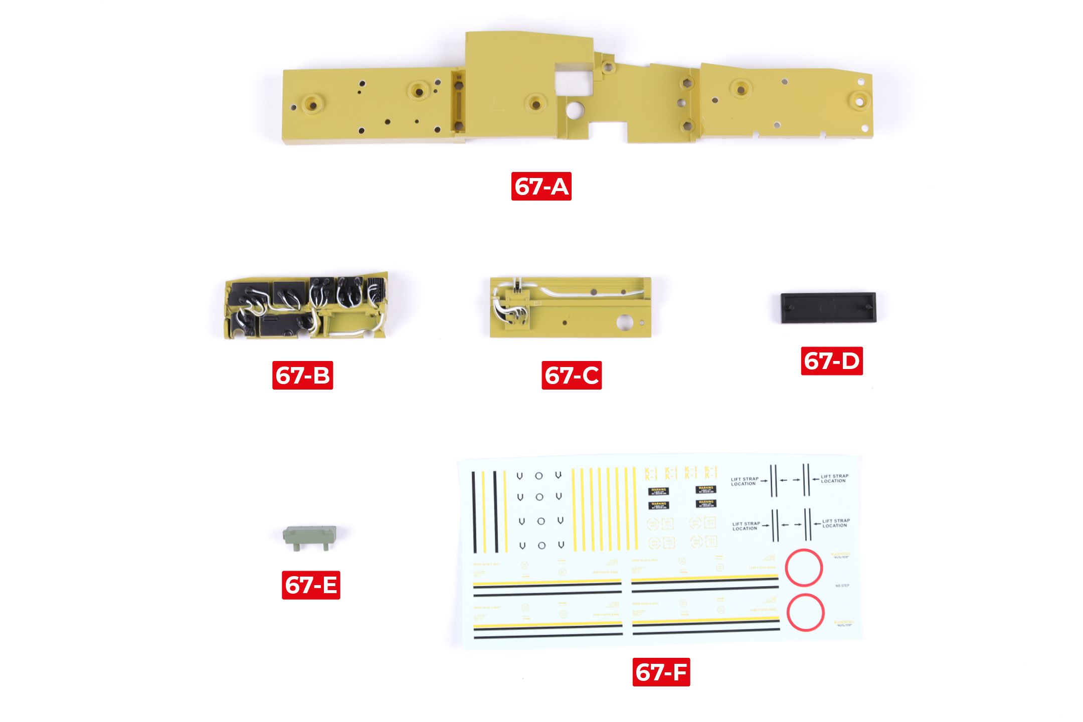
PARTS LIST
| 67-A | 67-D |
| 67-B | 67-E |
| 67-C | 67-F |
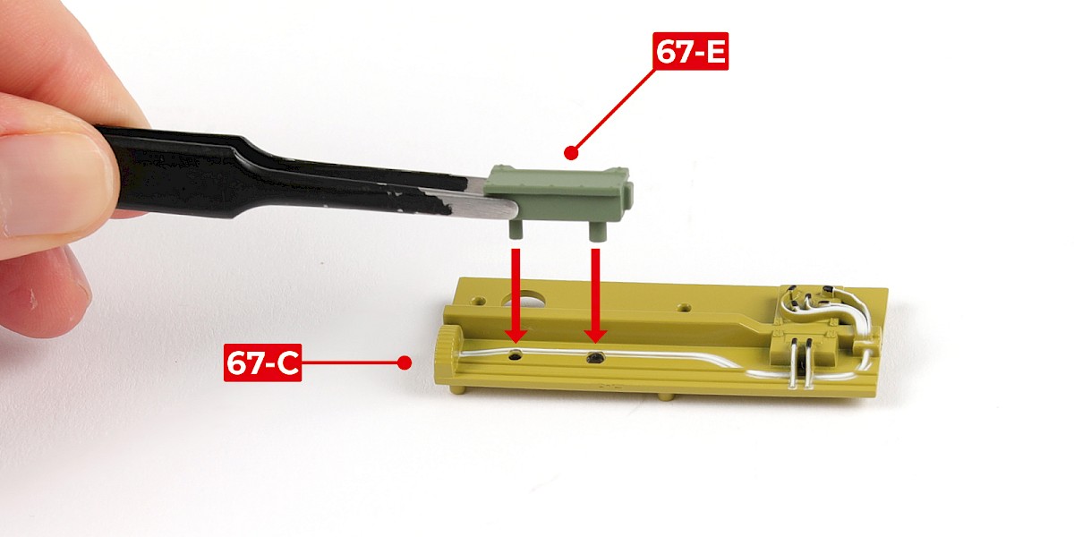
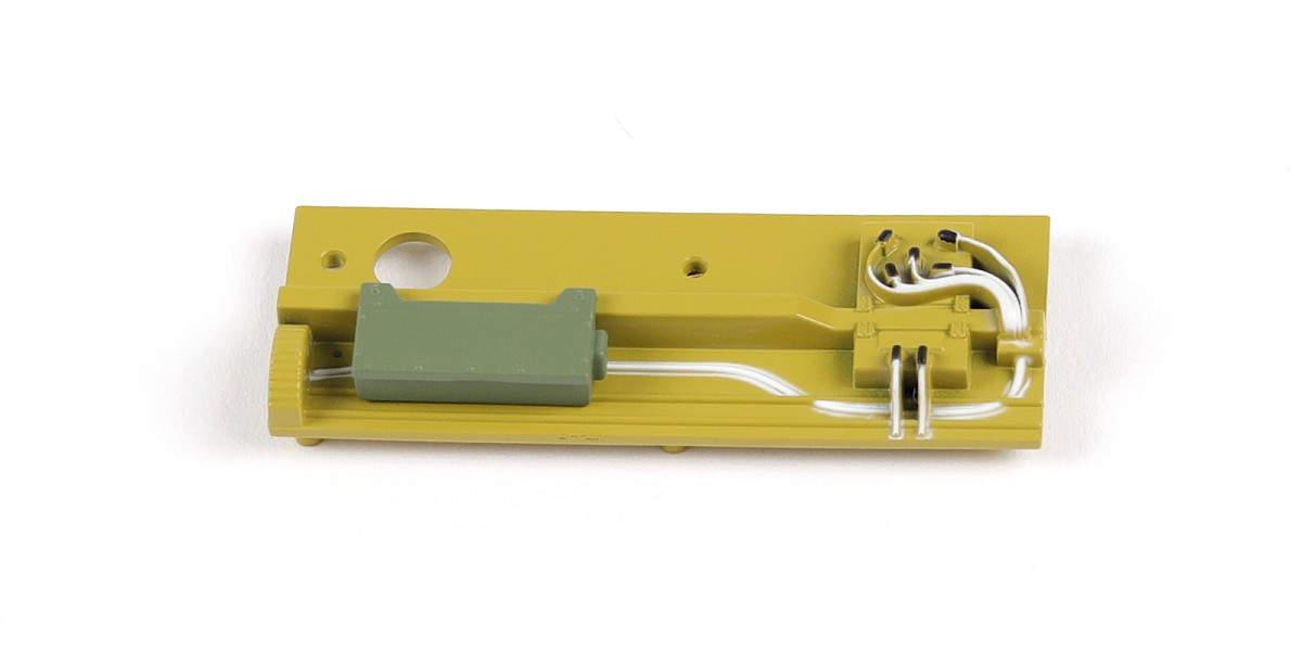
Step 1
Fit 67-E to 67-C.
Step 2
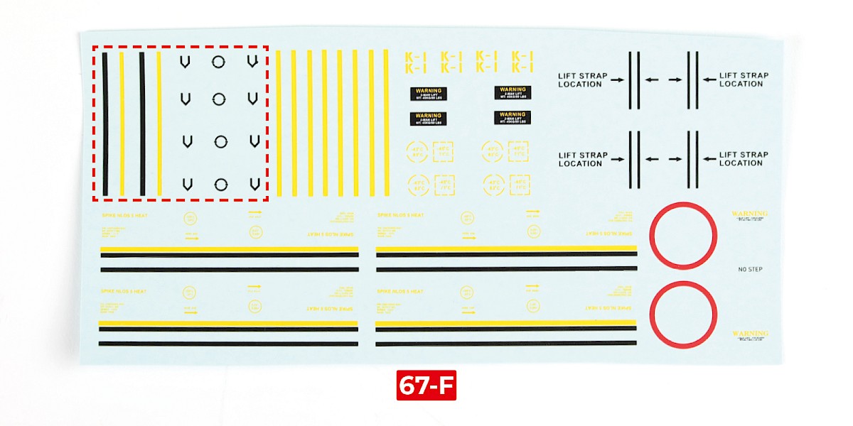
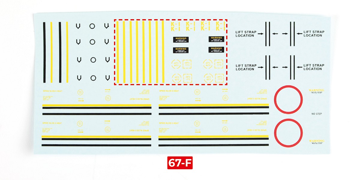
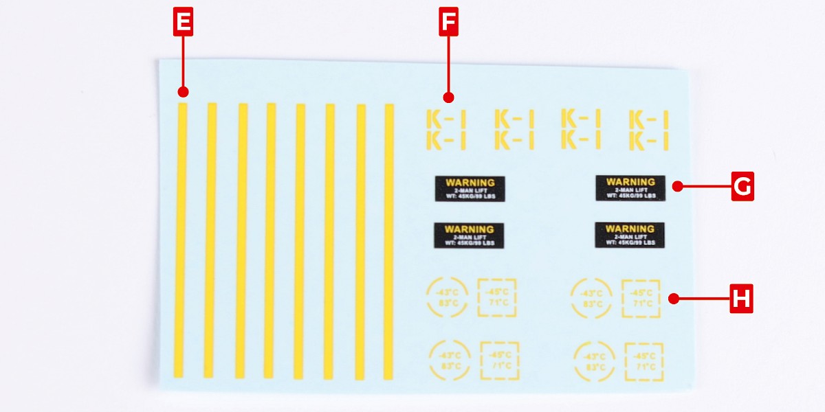
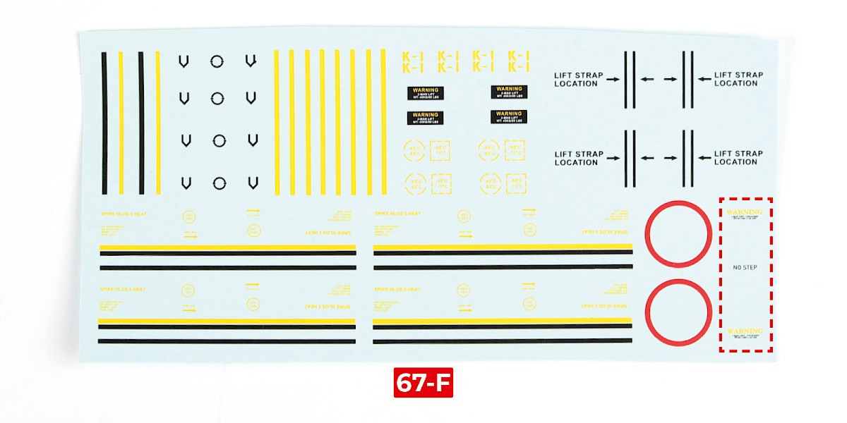
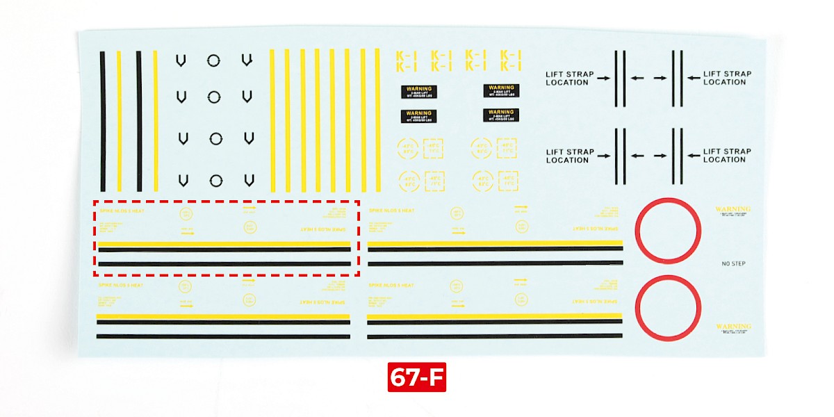
Take 67-F and cut out the decals outlined with the red dotted line.
Step 3
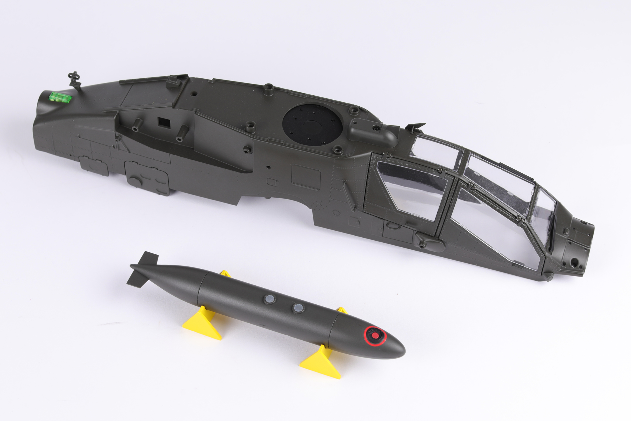
Apply decals A and B to the RCEFS tank (stage 53).
Align the decals with those on the opposite side.
Step 4
Apply the decals to the RCEFS tank from stage 54 in the same way.
STAGE COMPLETE
PARTS LIST
| 68-A | 68-G |
| 68-B | 68-H |
| 68-C | 68-J |
| 68-D x7 | 68-K |
| 68-E | 68-L |
| 68-F |
Step 1
Fit 68-F to 68-E.
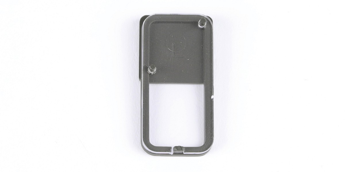
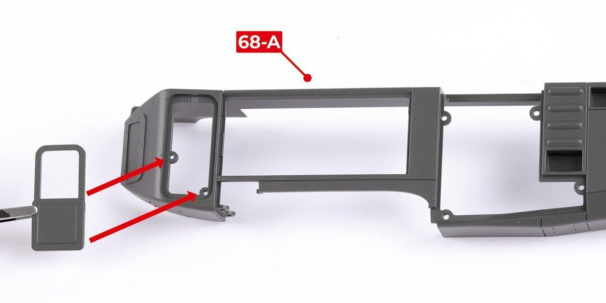
Step 2
Fit the assembly to 68-A.
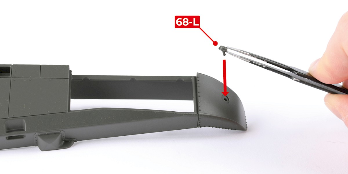
Step 3
Fit 68-L to the assembly.

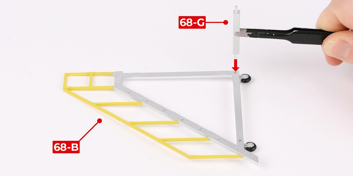
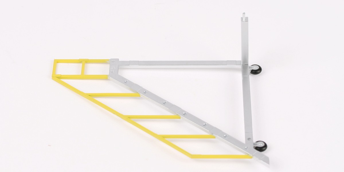
Step 4
Glue 68-G to 68-B.
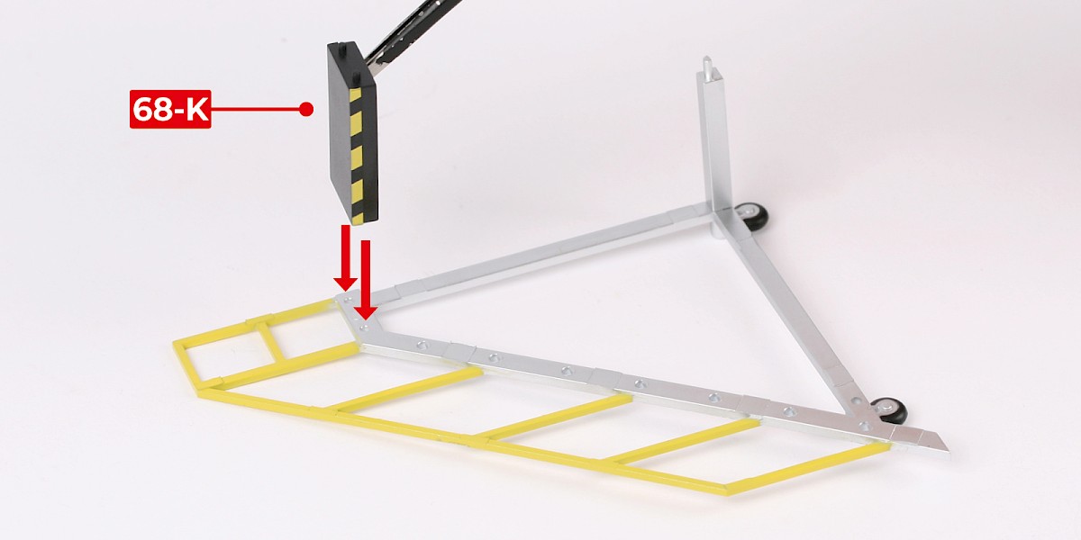
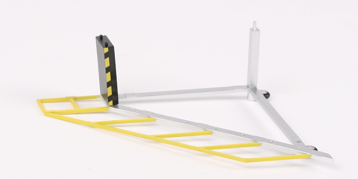
Step 5
Glue 68-K to the assembly.
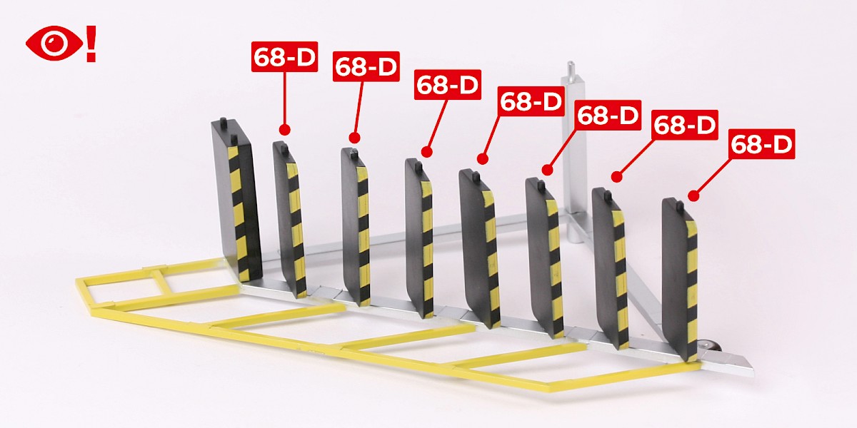
Step 6
Continue to glue 68-D to the assembly.
Note: Do not allow the glue to dry. You may need to adjust these parts in the next step.
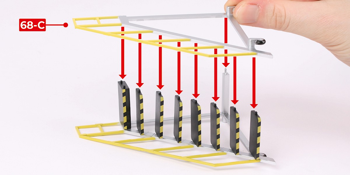
Step 7
Glue 68-C to the assembly.
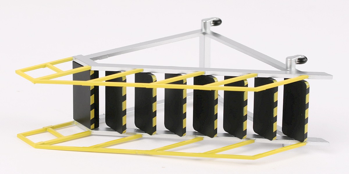
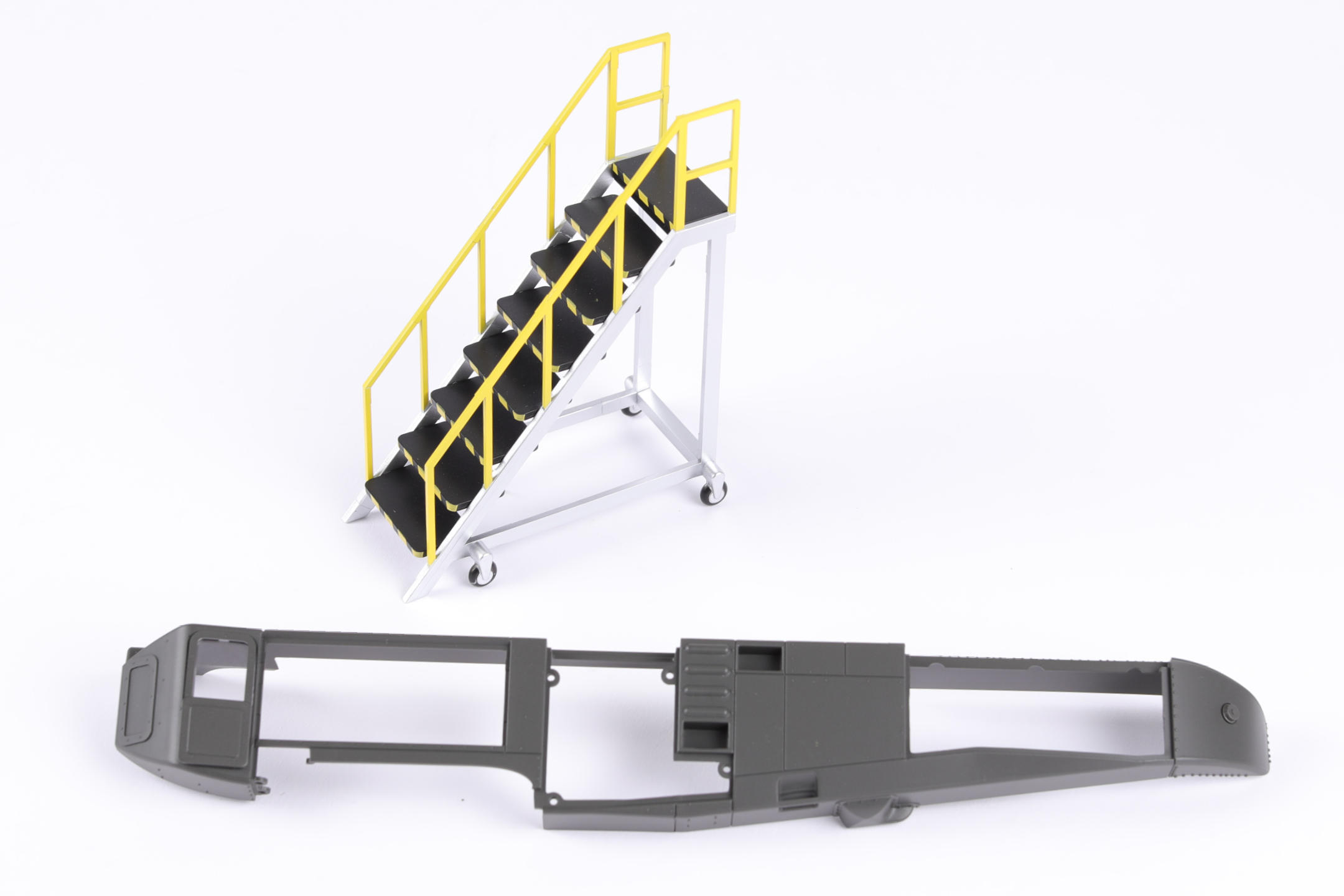
STAGE COMPLETE
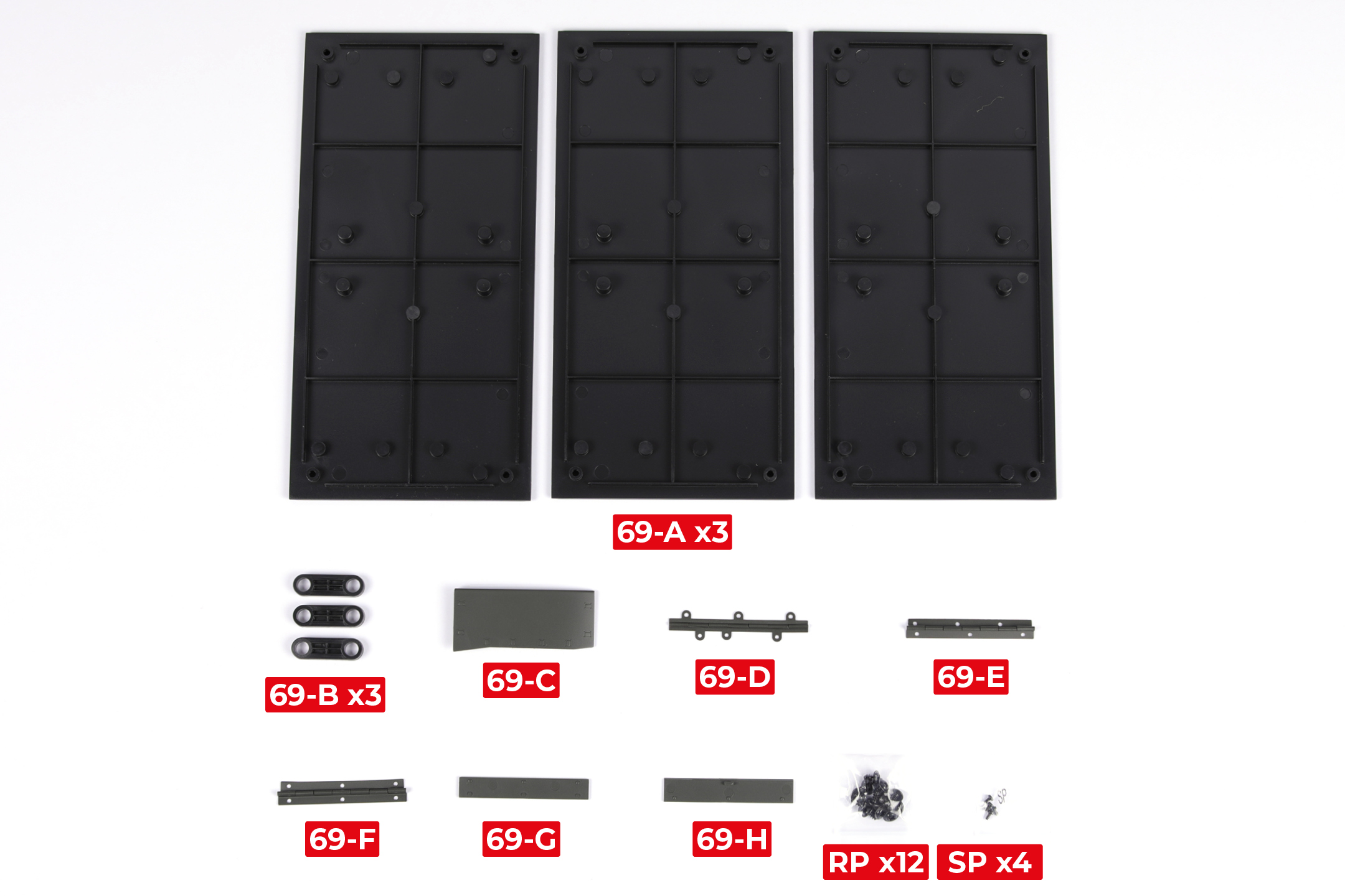
PARTS LIST
| 69-A | 69-F |
| 69-B | 69-G |
| 69-C | 69-H |
| 69-D | RP x12 |
| 69-E | SP x4 |
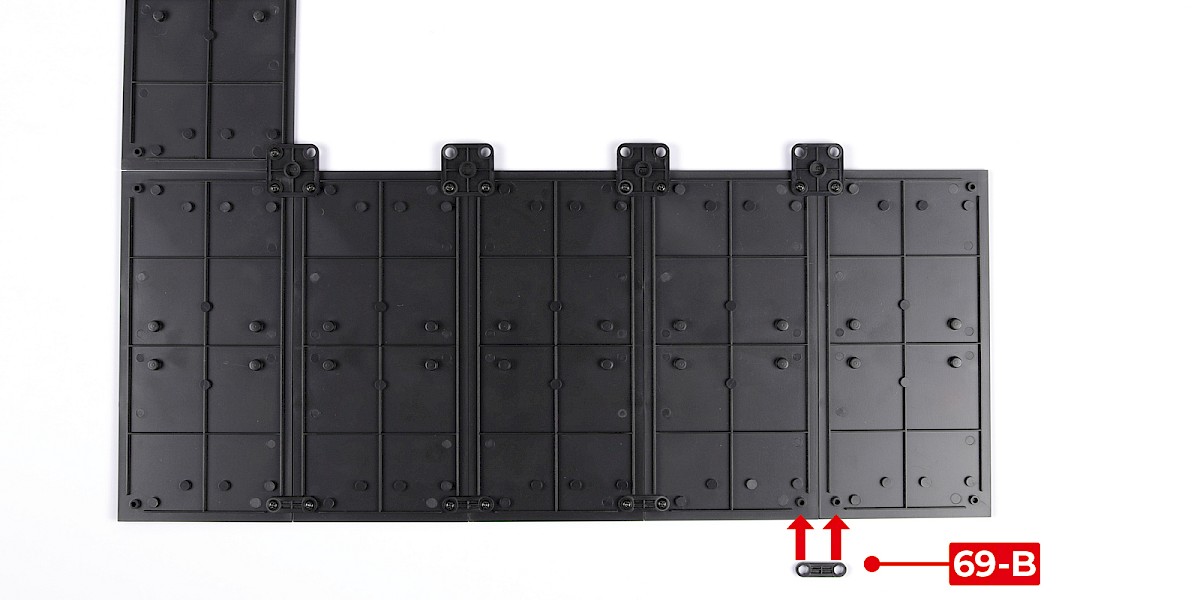
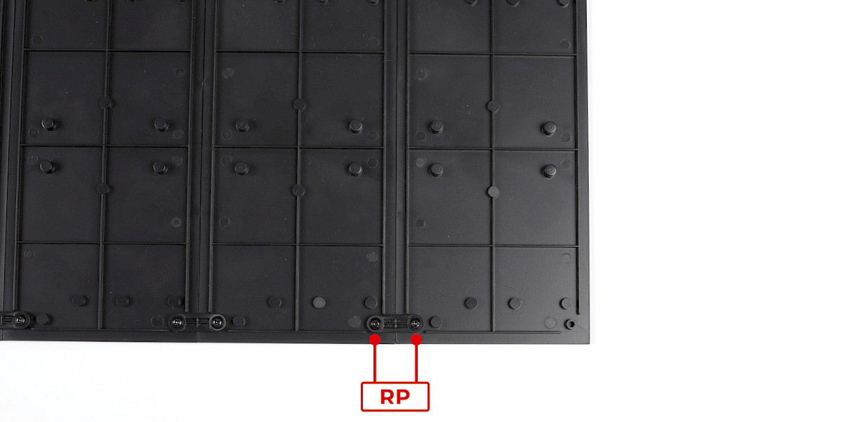
Step 1
Fit 69-B to the assembly from stage 62.
Secure with 2x RP.
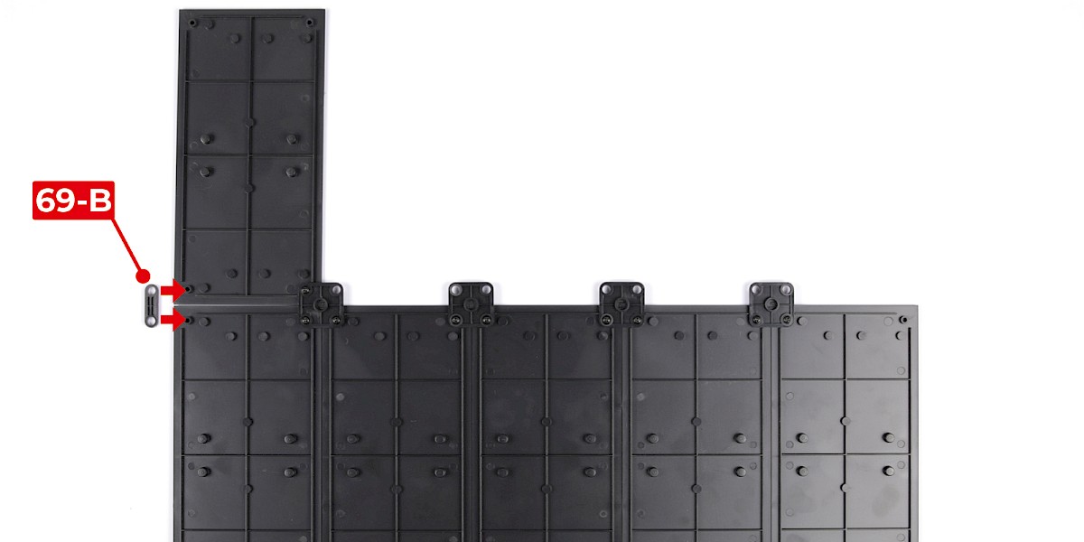
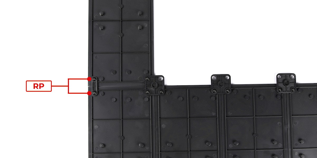
Step 2
Fit another 69-B to the assembly as shown.
Secure with 2x RP.
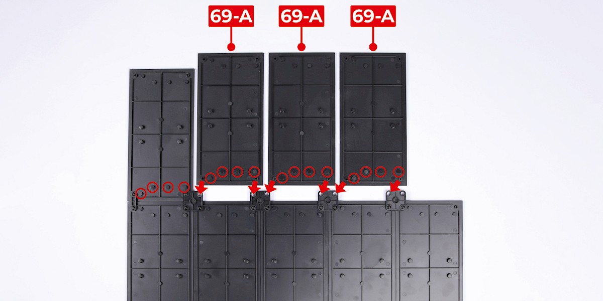
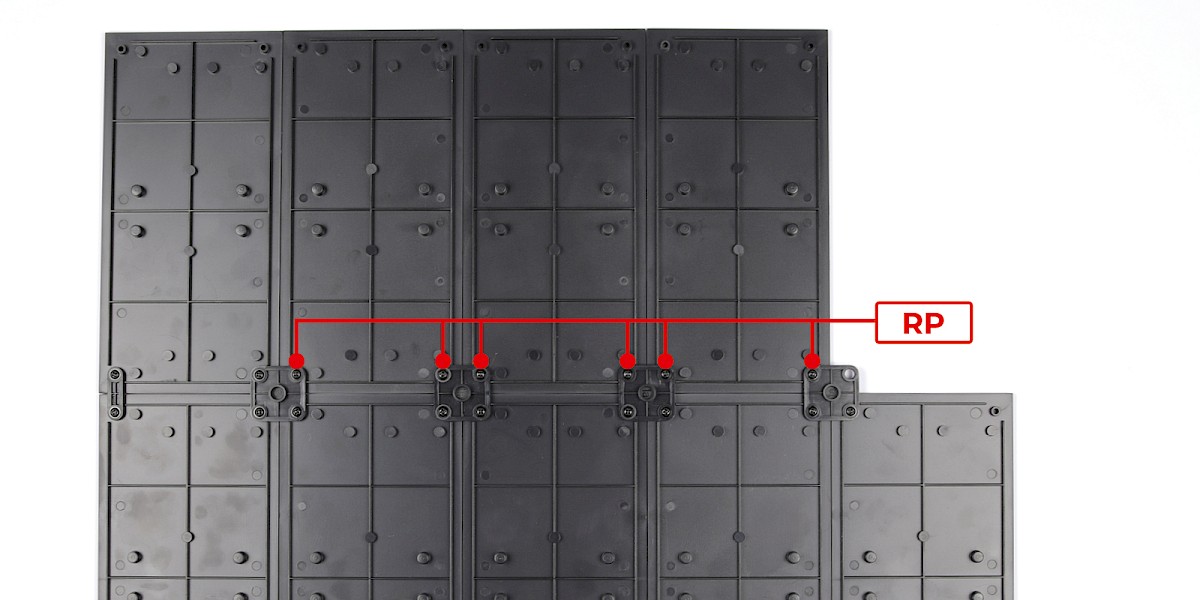
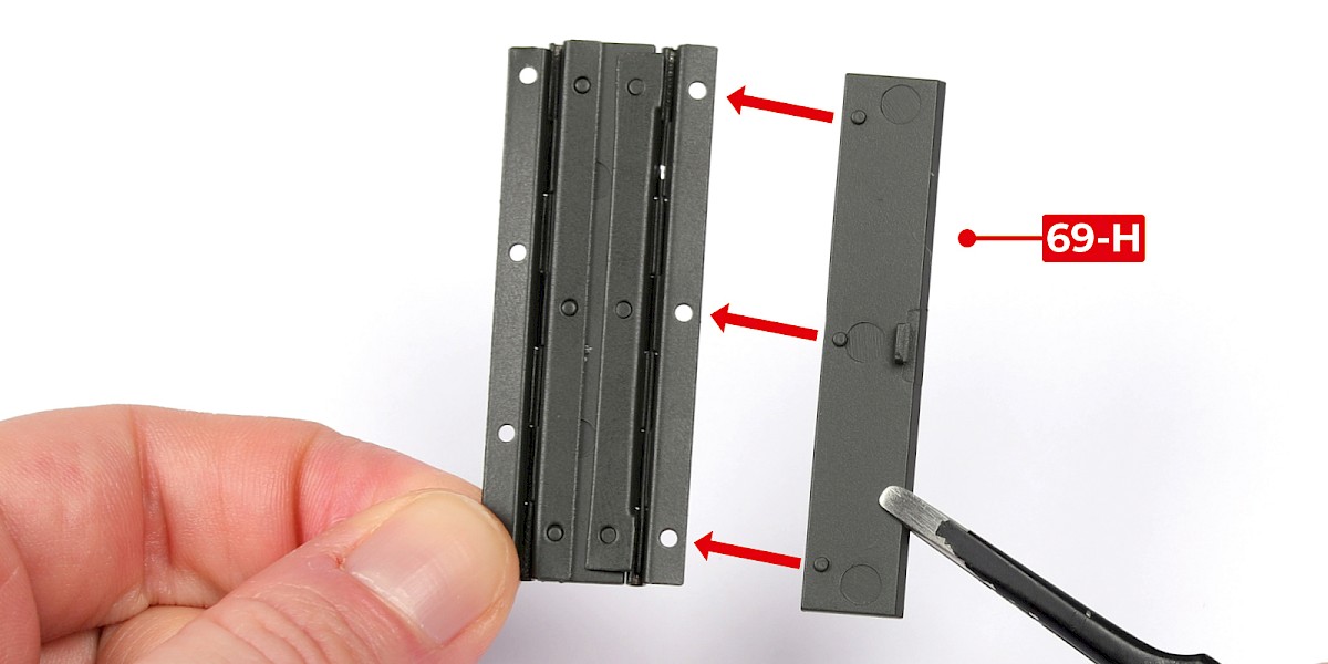
Step 3
Fit 69-A to the assembly. Make sure the parts are in the orientation shown.
Secure with 6x RP.
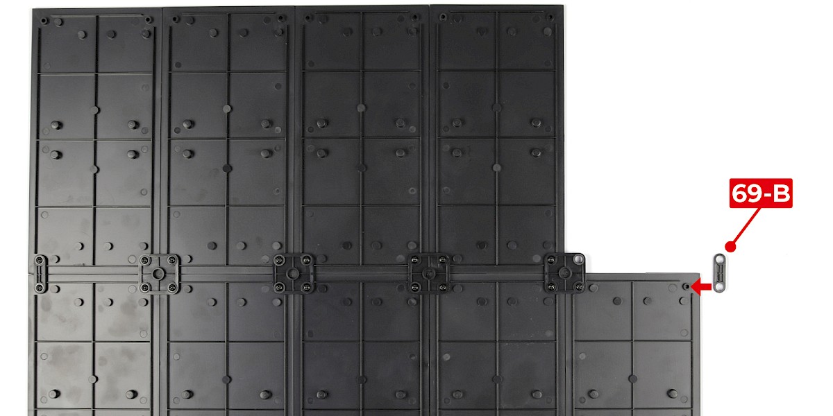
Step 4
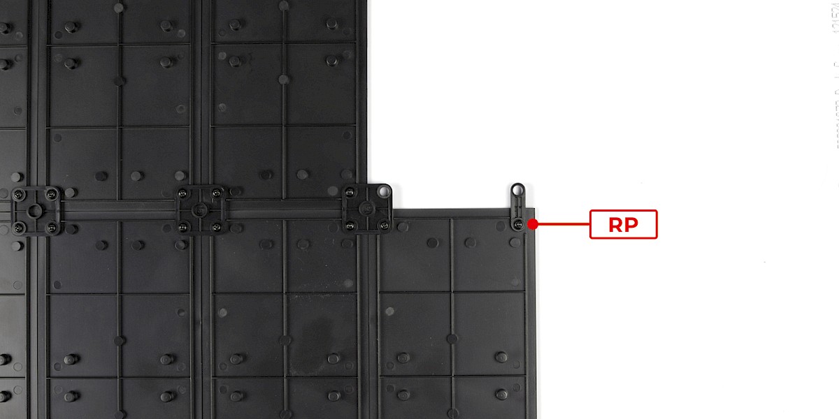
Fit another 69-B to the assembly as shown.
Secure with 1x RP.
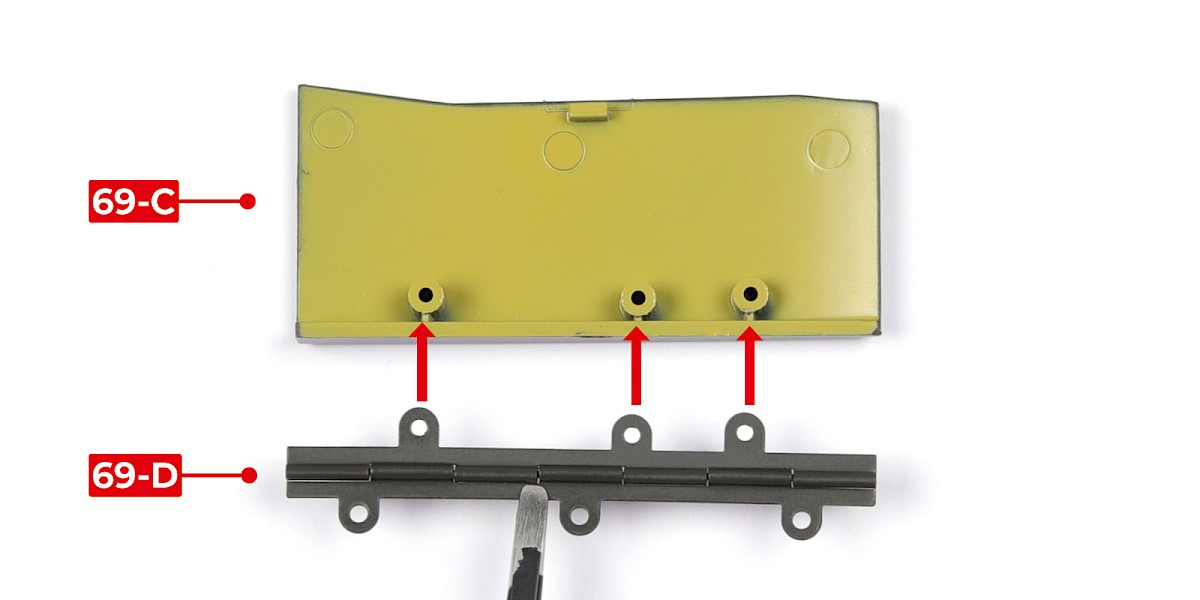
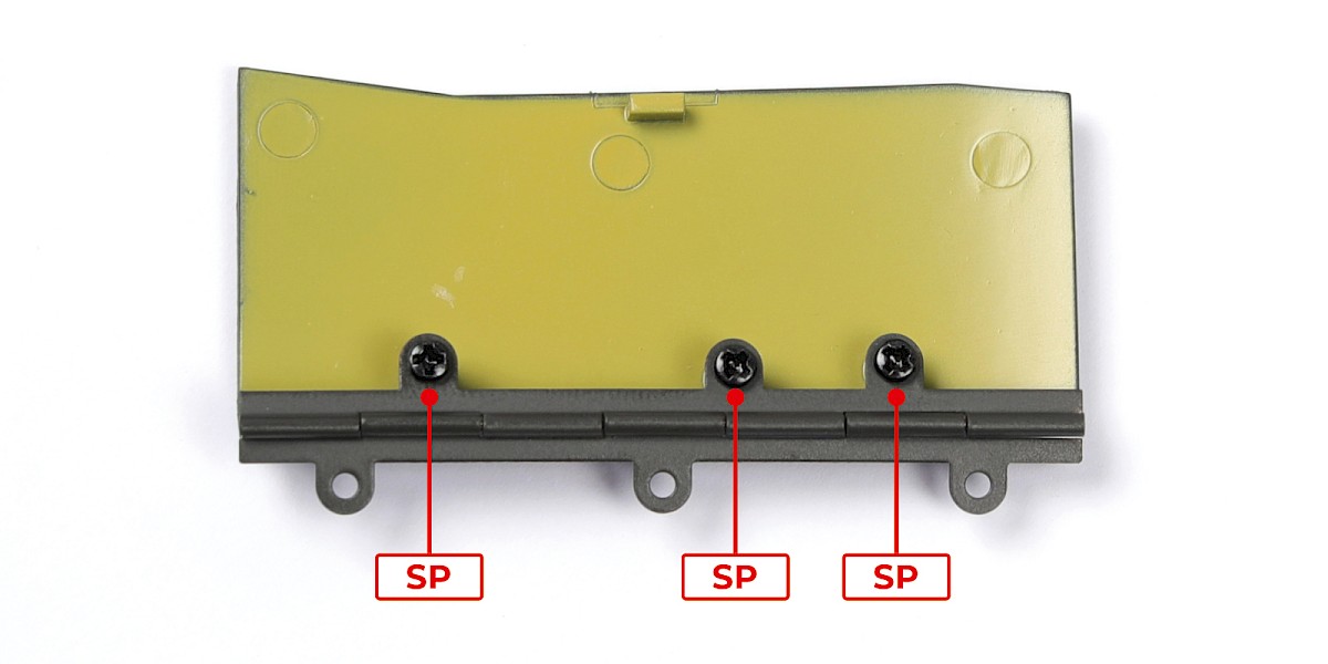
Step 5
Fit 69-D to 69-C.
Secure with 3x SP.
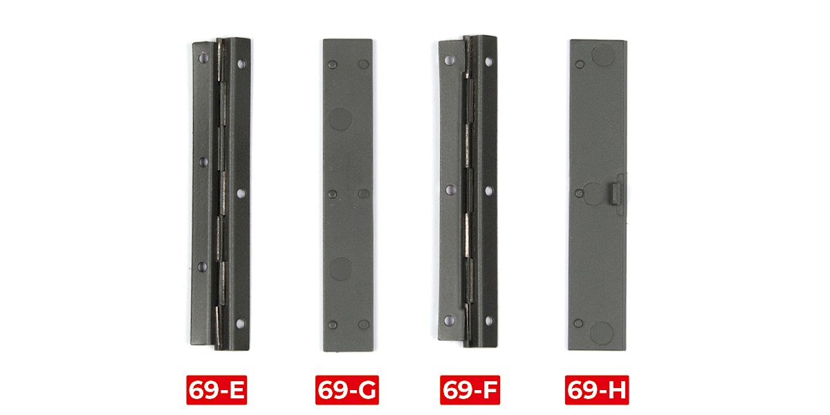
Step 6
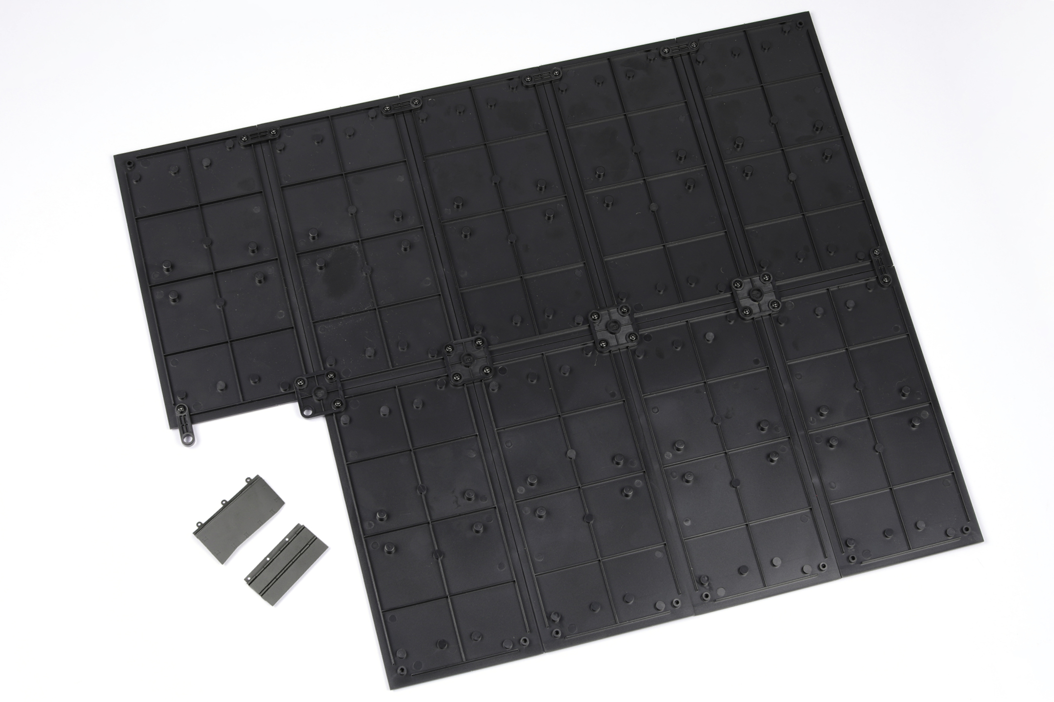
You will now build the ammunition-bay door.
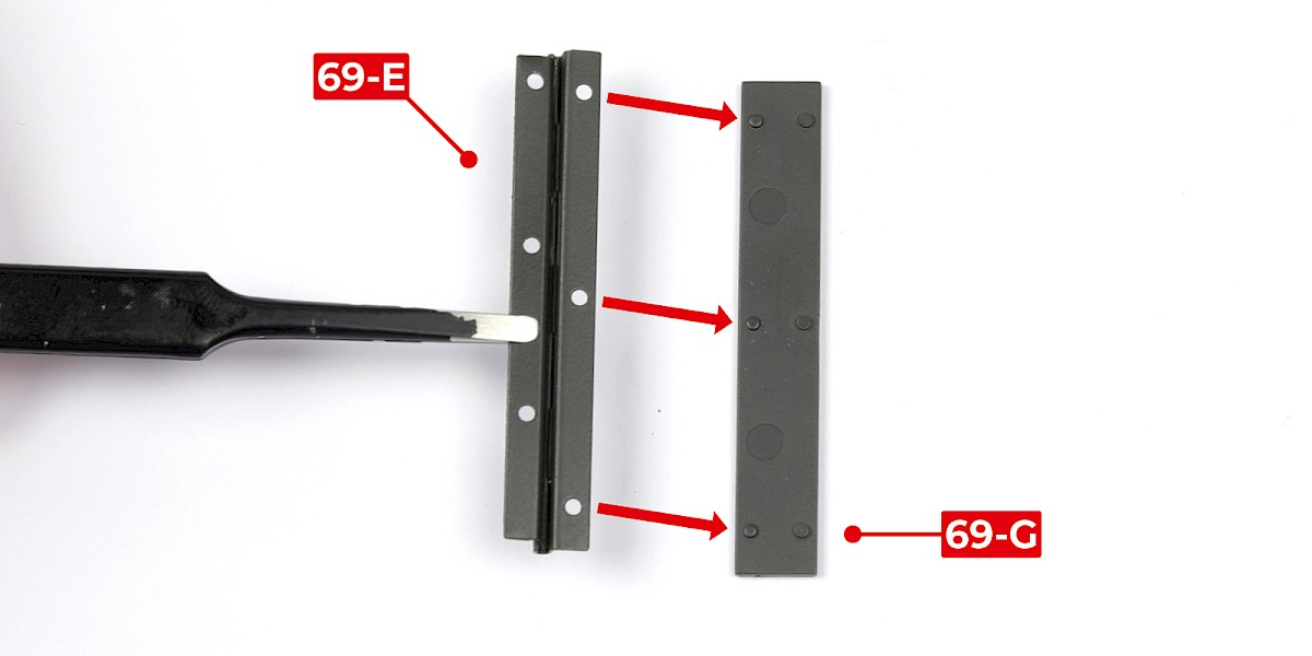
Place 69-E, 69-G, 69-F and 69-H on your work surface as shown.
Step 7
Glue 69-E to 69-G. Ensure 69-E is in the orientation shown.
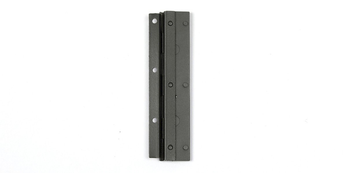
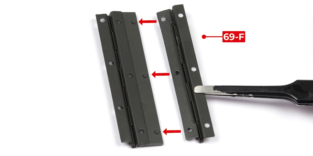
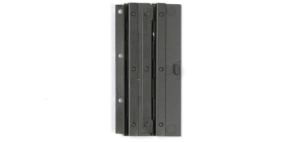
Step 8
Glue 69-F to the assembly.
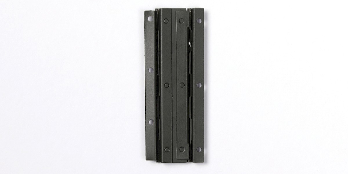
Step 9
Glue 69-H to the assembly.
STAGE COMPLETE
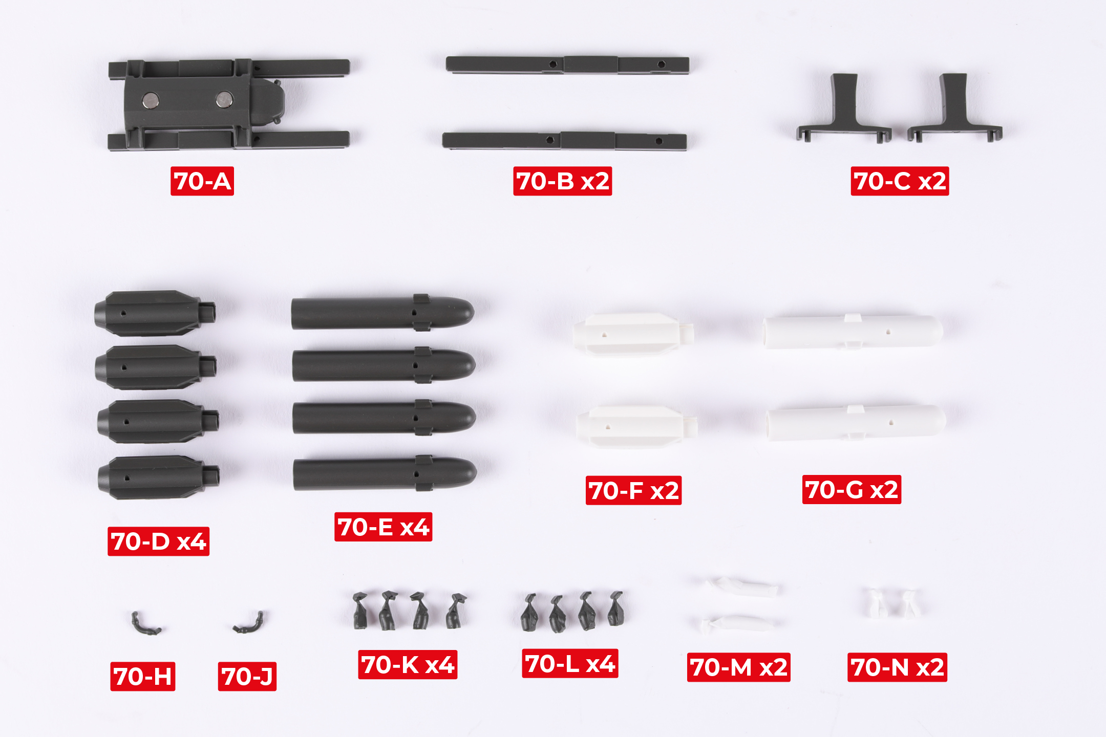
PARTS LIST
| 70-A | 70-H |
| 70-B x2 | 70-J |
| 70-C x2 | 70-K x4 |
| 70-D x4 | 70-L x4 |
| 70-E x4 | 70-M x2 |
| 70-F x2 | 70-N x2 |
| 70-G x2 |
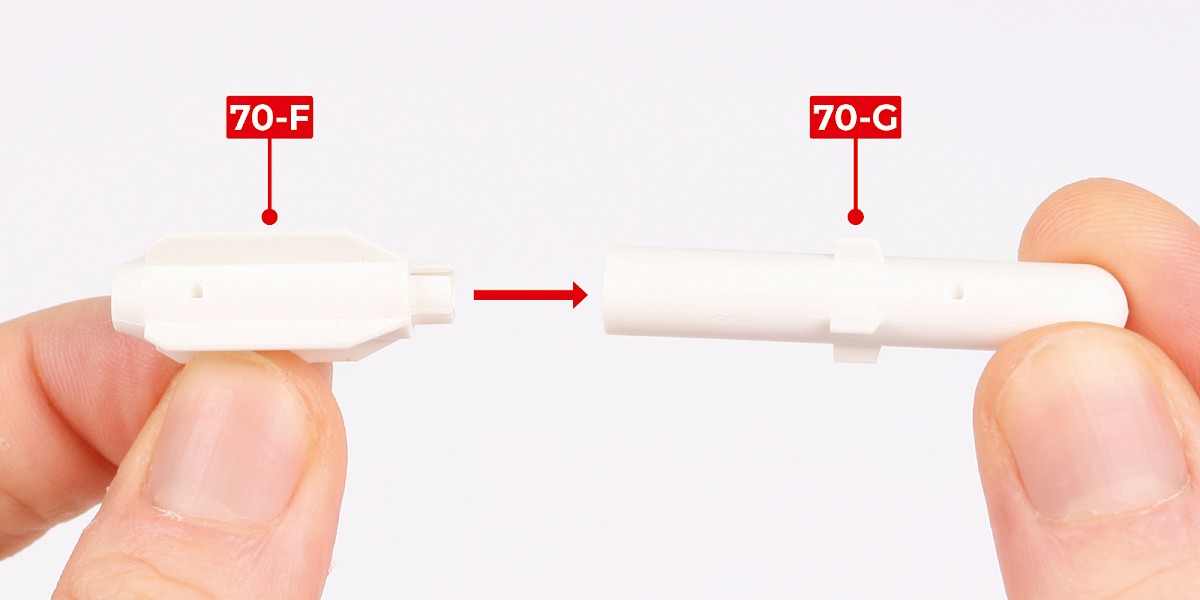
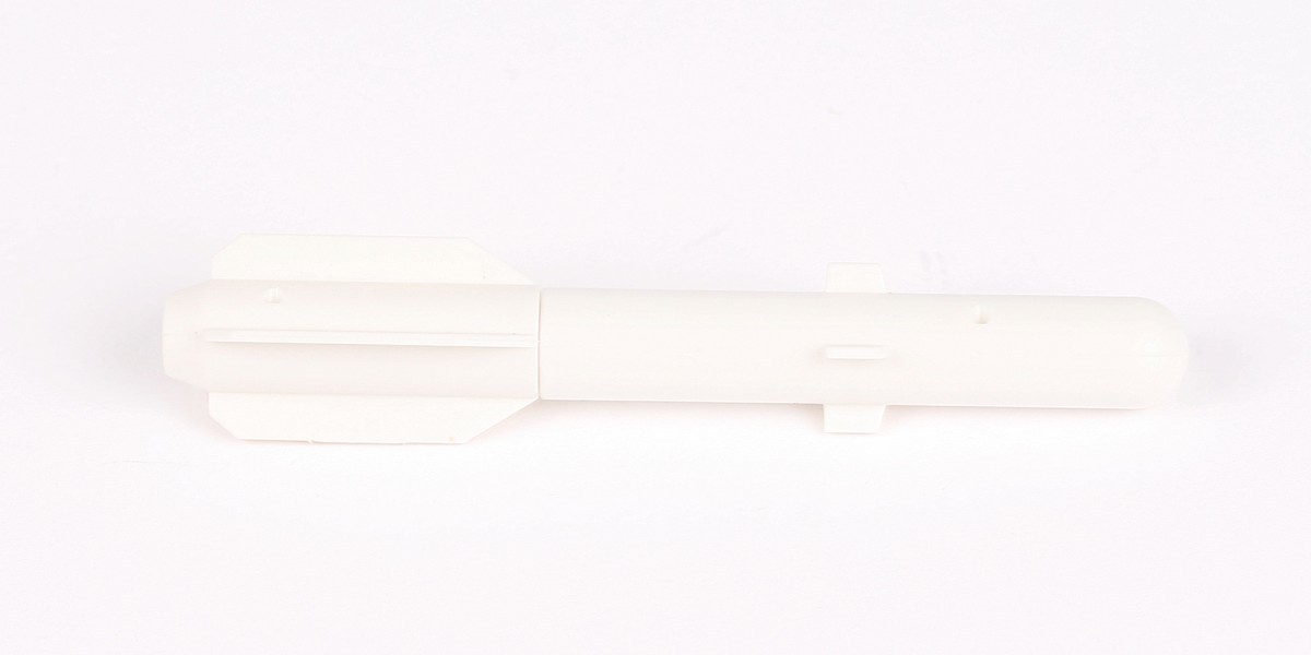
Step 1
Fit 70-F to 70-G.
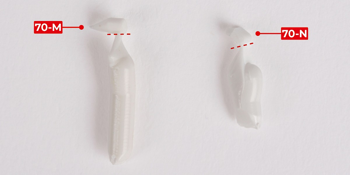
Step 2
Cut parts 70-M and 70-N off the sprues.
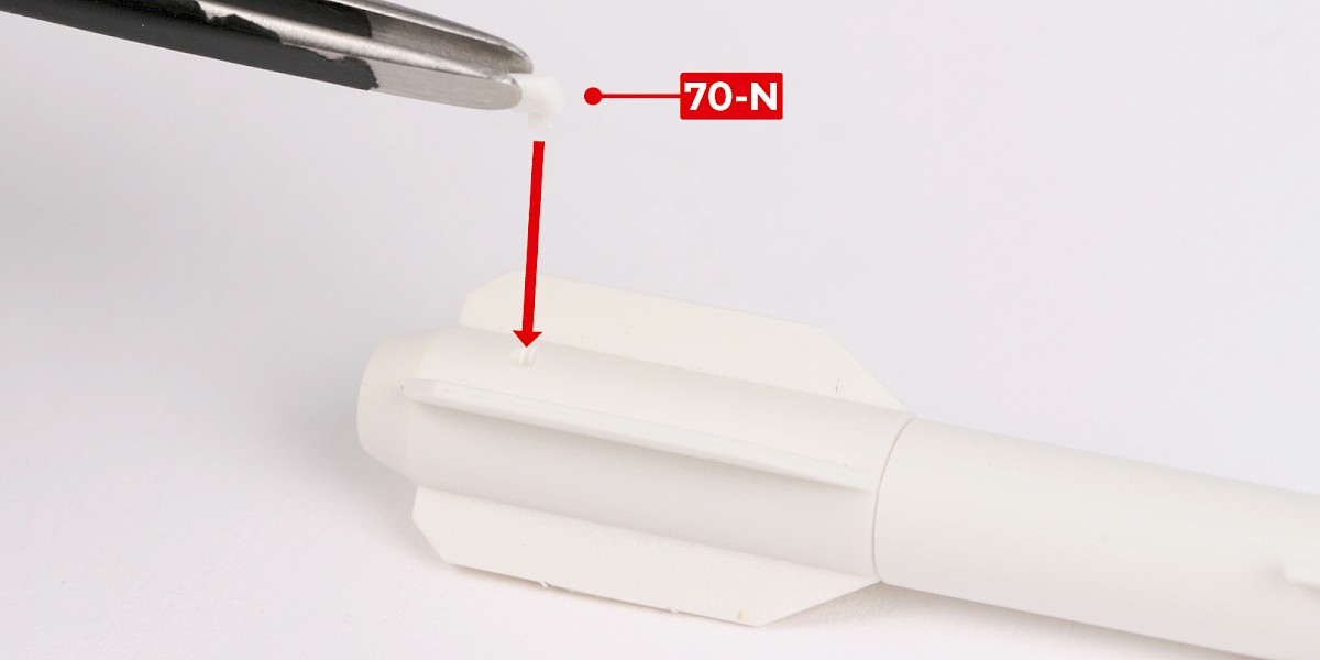
Step 3
Glue 70-N to the assembly.
Step 4
Glue 70-M to the assembly.
Step 5
Cut the decals outlined in red from 67-F.
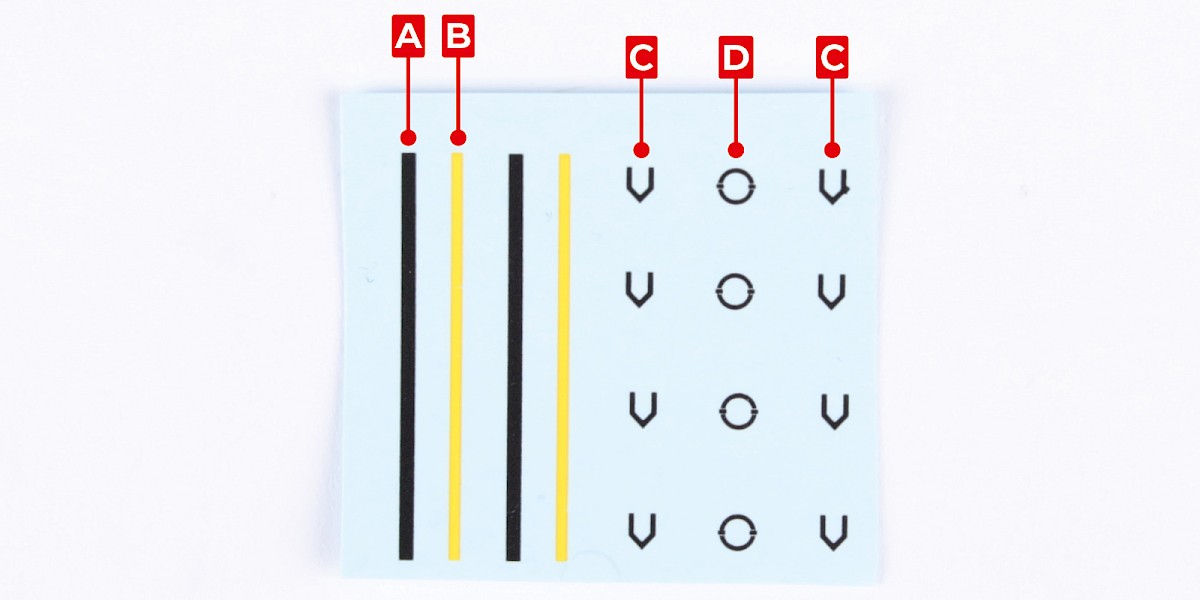
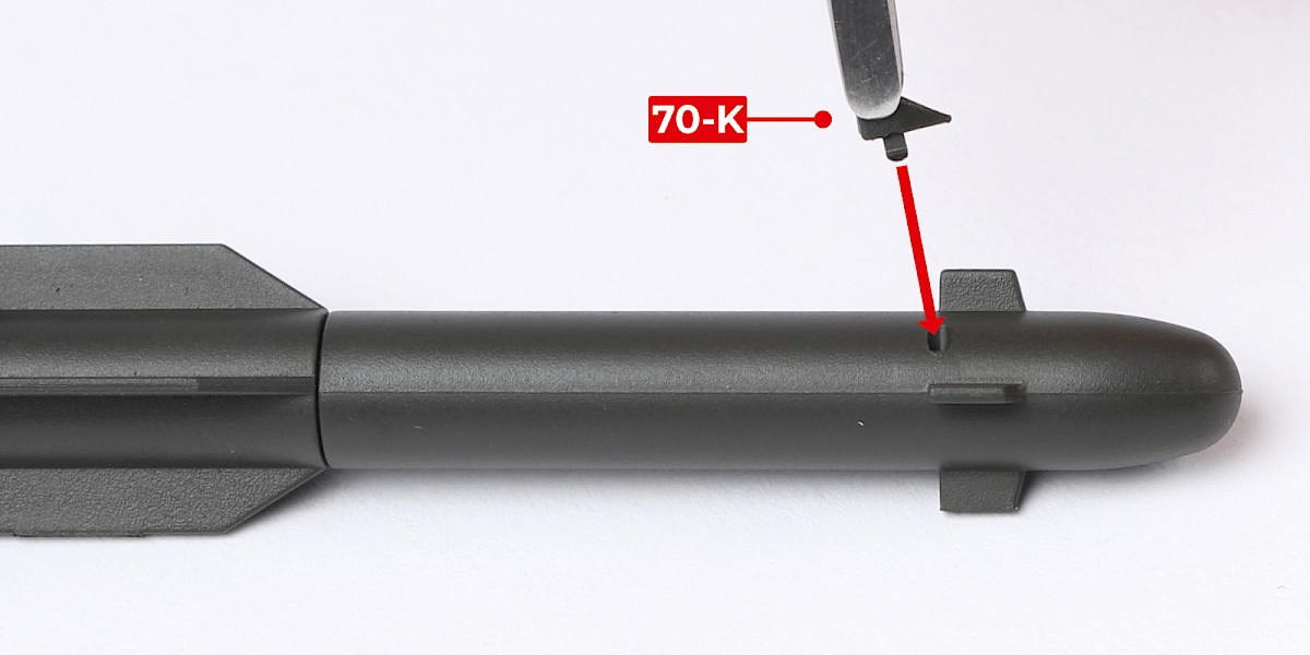
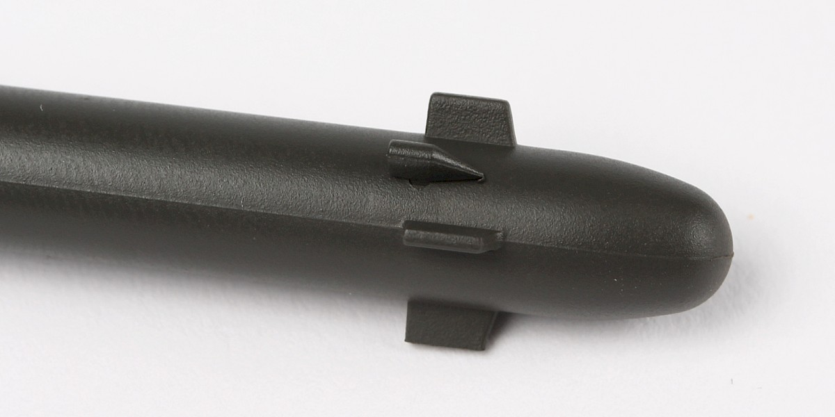
Step 6
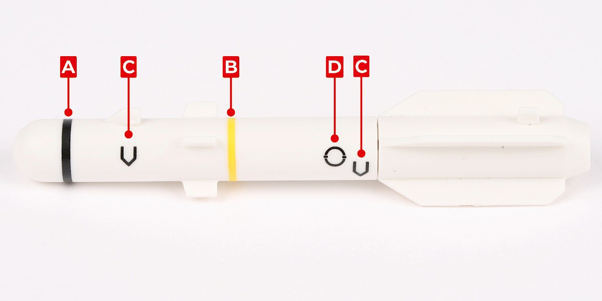
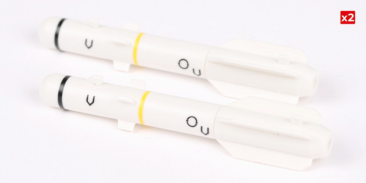
Apply decals A, B, C and D to the missile.
Repeat this process to assemble two missiles.
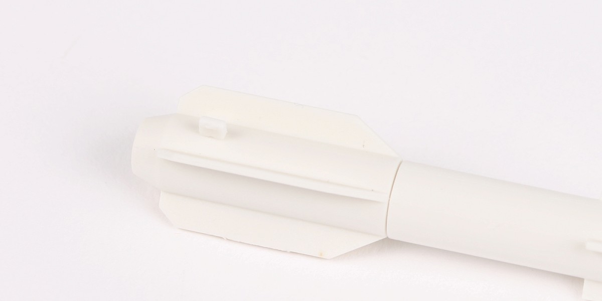
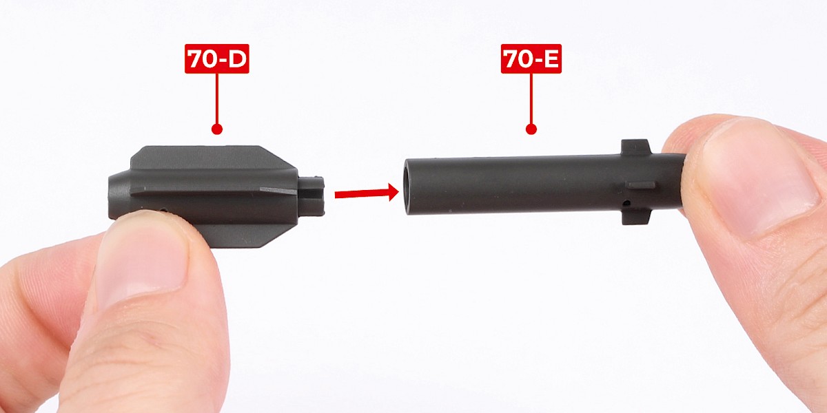
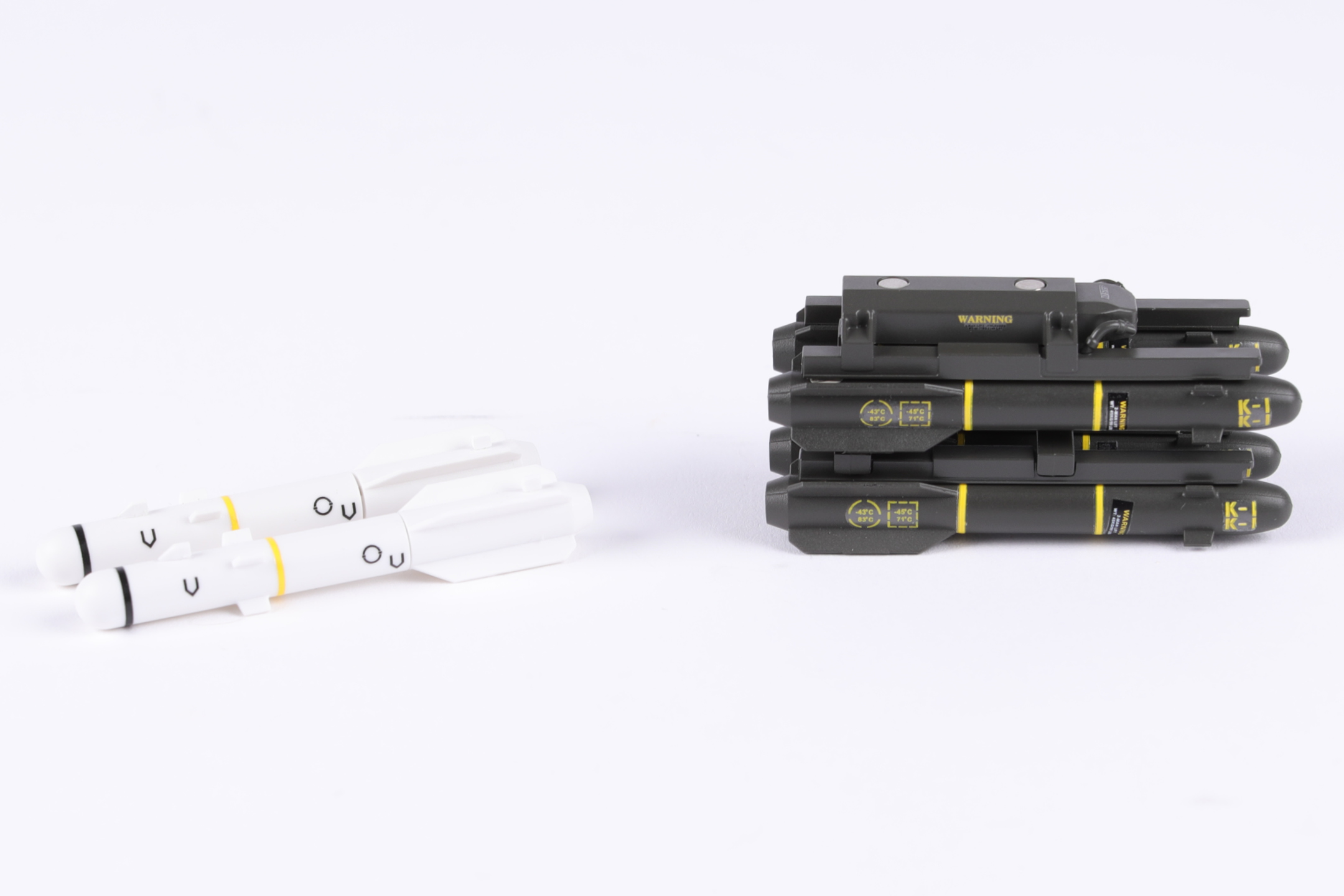
Step 7
You will now build the Hellfire missiles and an M299 missile launcher.
Fit 70-D to 70-E.
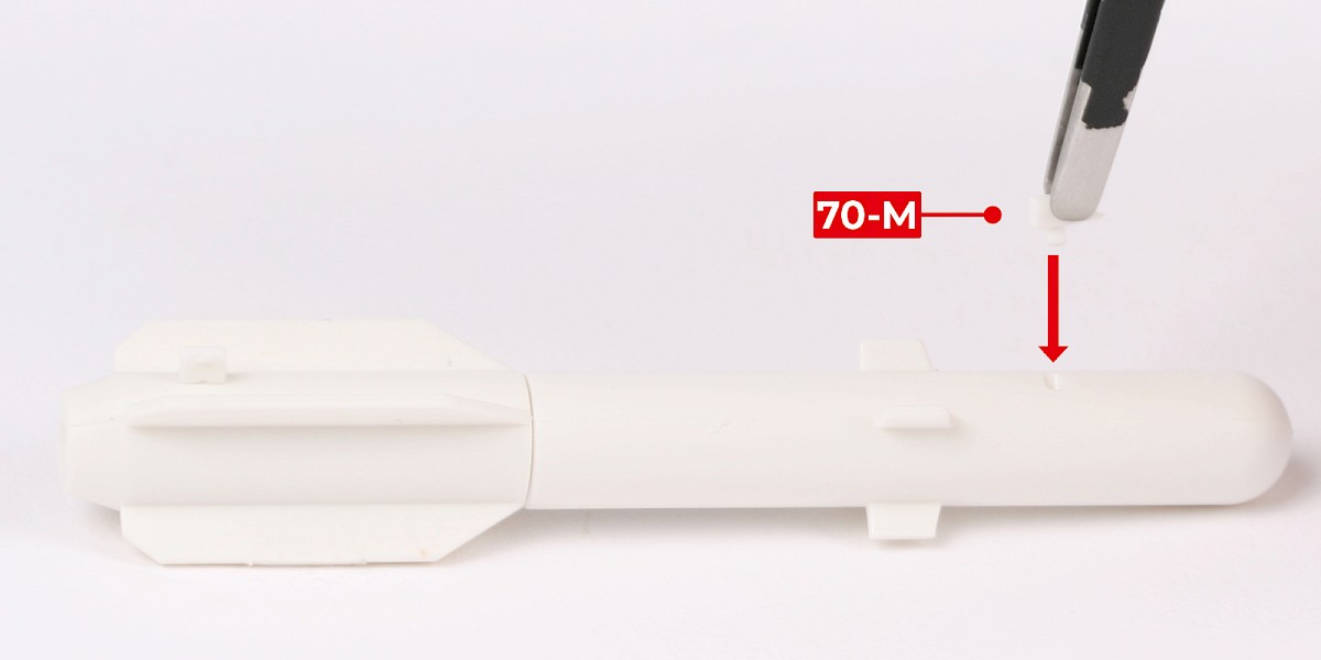
Step 8
Cut parts 70-L and 70-K off the sprues.
Step 9
Glue 70-L to the assembly.
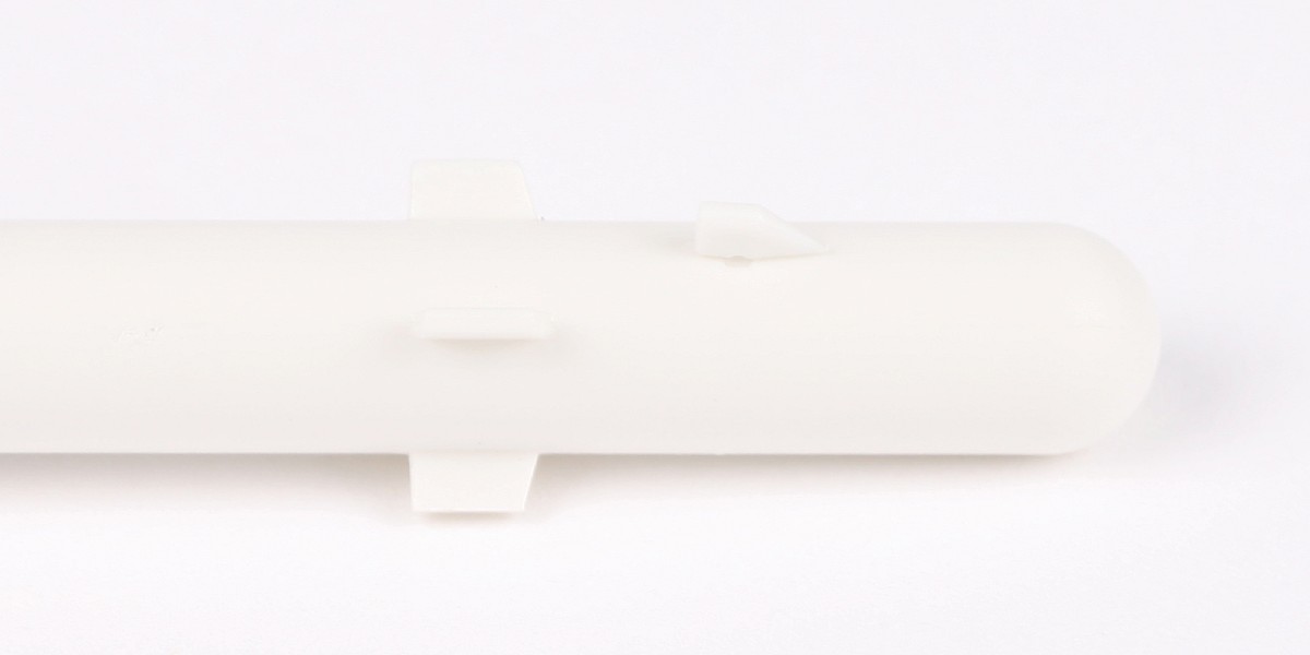
Step 10
Glue 70-K to the assembly.
Step 11
Cut the decals outlined in red from 67-F.
Step 12
Apply decals E, F, G and H to the missile.
Repeat this process to assemble four missiles.
Step 13
Glue one of the missiles to 70-A.
Step 14
Glue a second missile in the same way.
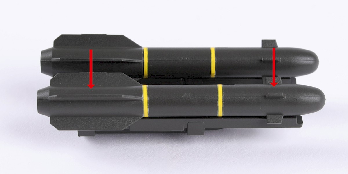
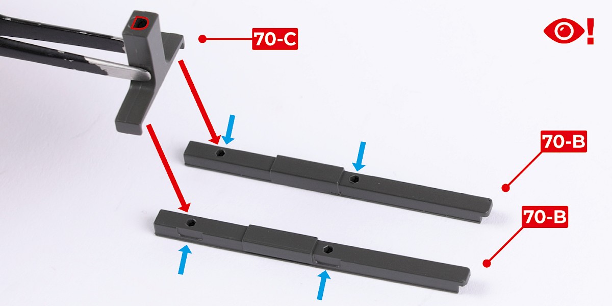
Step 15
Fit 70-C to 70-B. Make sure the parts are in the orientation shown. The recesses on parts 70-B (blue arrows) should face outwards.
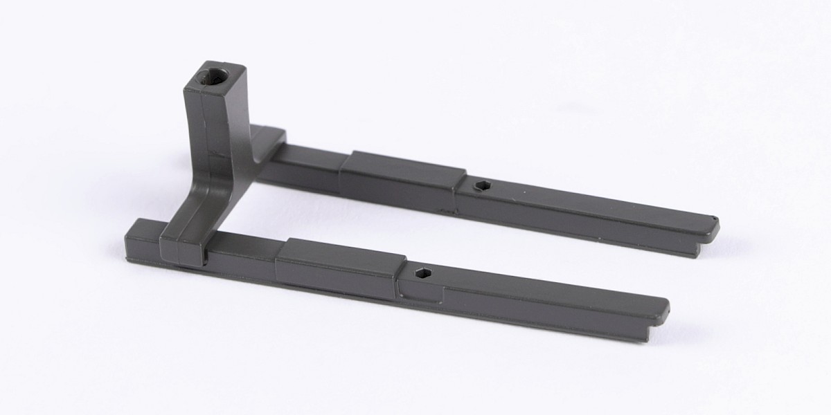
Step 16
Fit another 70-C as shown.
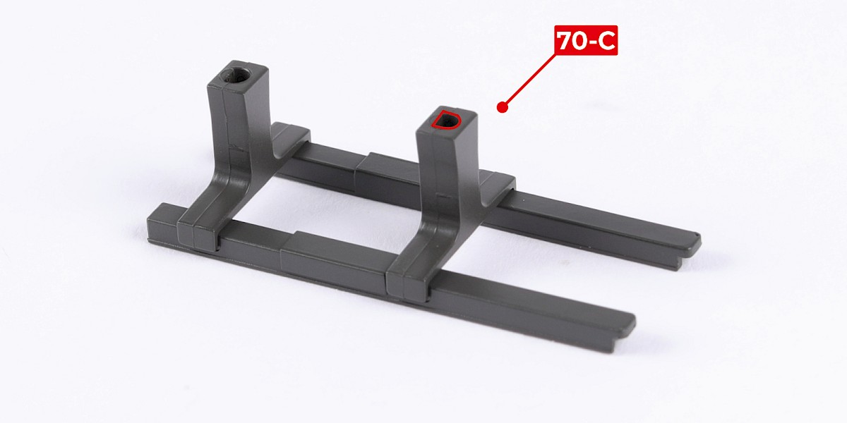
Step 17
Fit the two assemblies together.
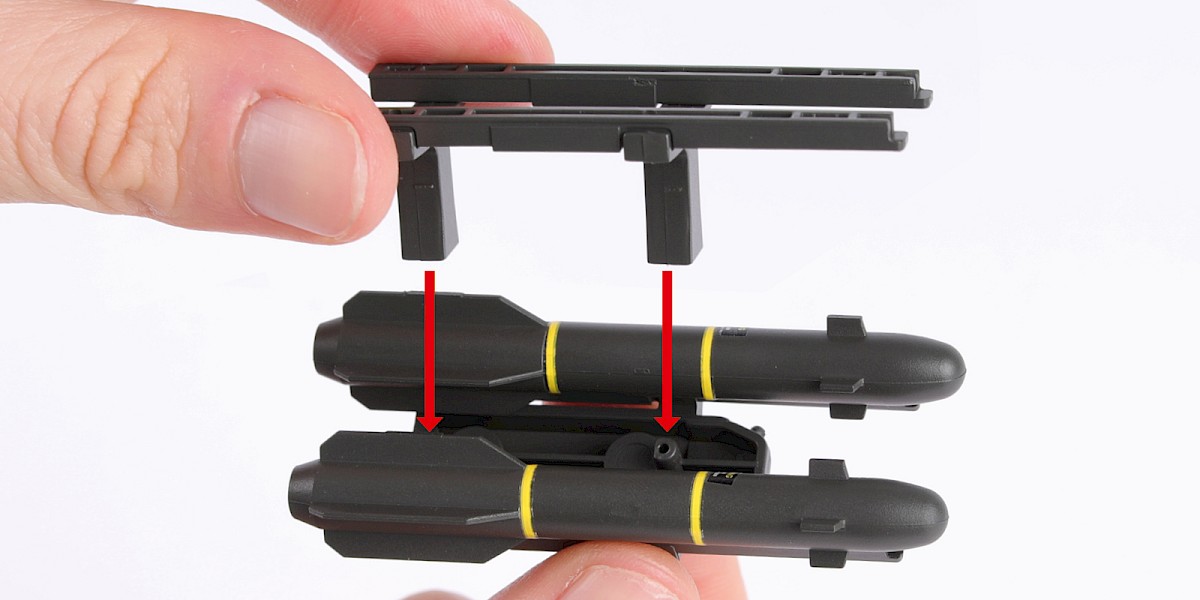
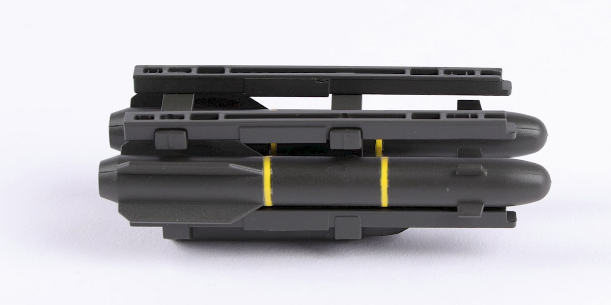
Step 18
Glue two missiles to the assembly.
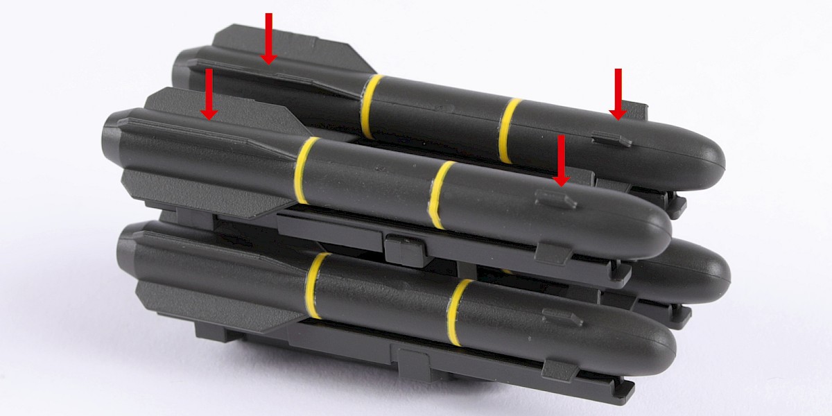
Step 19
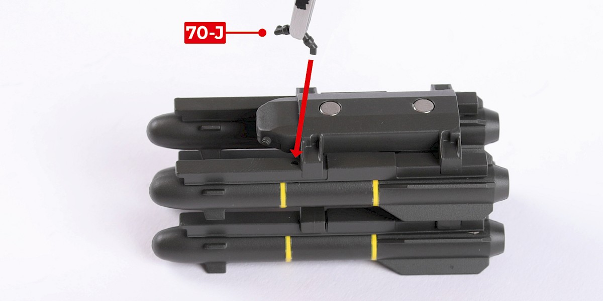
Parts 70-H and 70-J have shaped fittings.
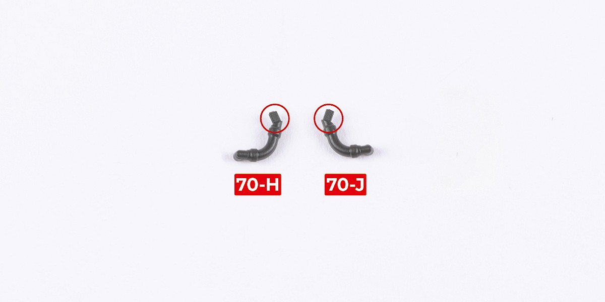
Step 20
Fit 70-J to the assembly.
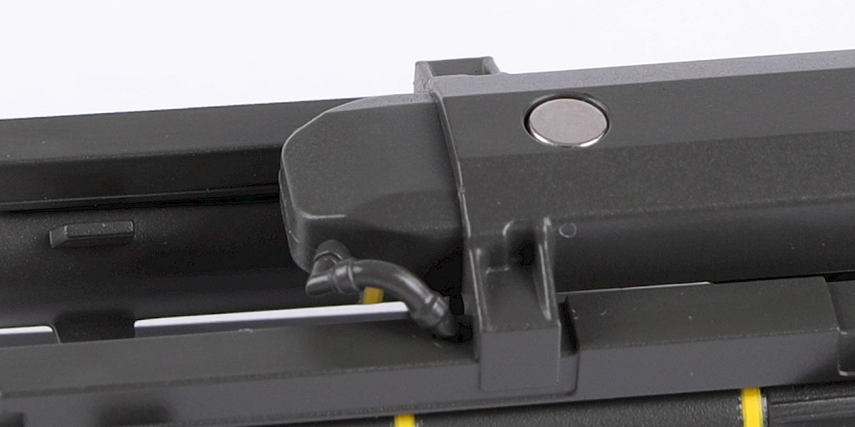
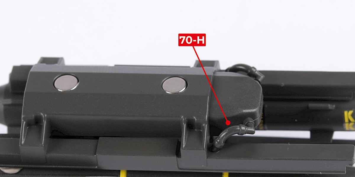
Step 21
Fit 70-H to the assembly.
Step 22
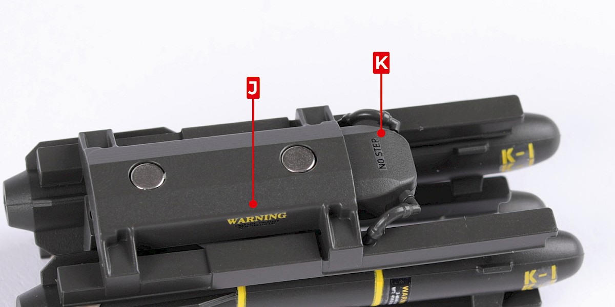
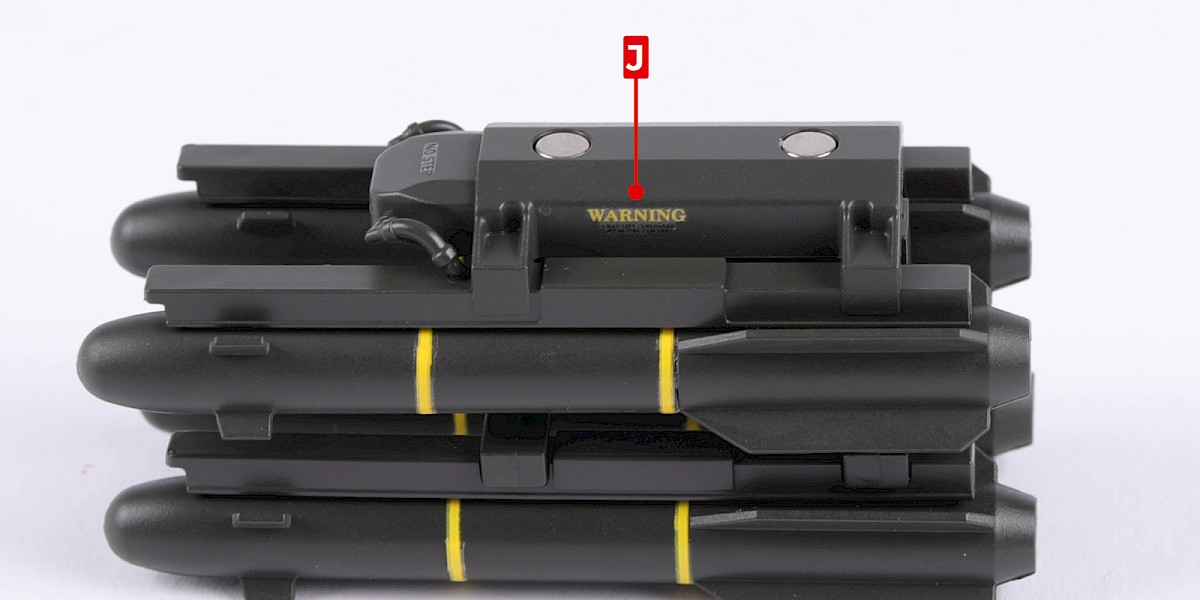
Cut the decals outlined in red from 67-F.
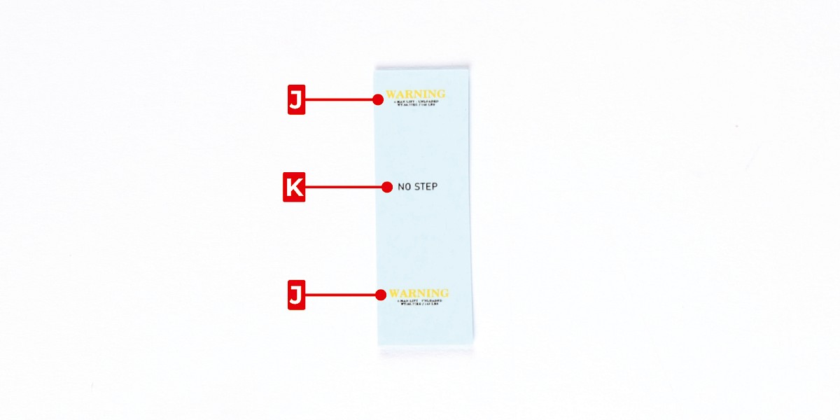
Step 23
Apply decals J and K to the assembly.
STAGE COMPLETE
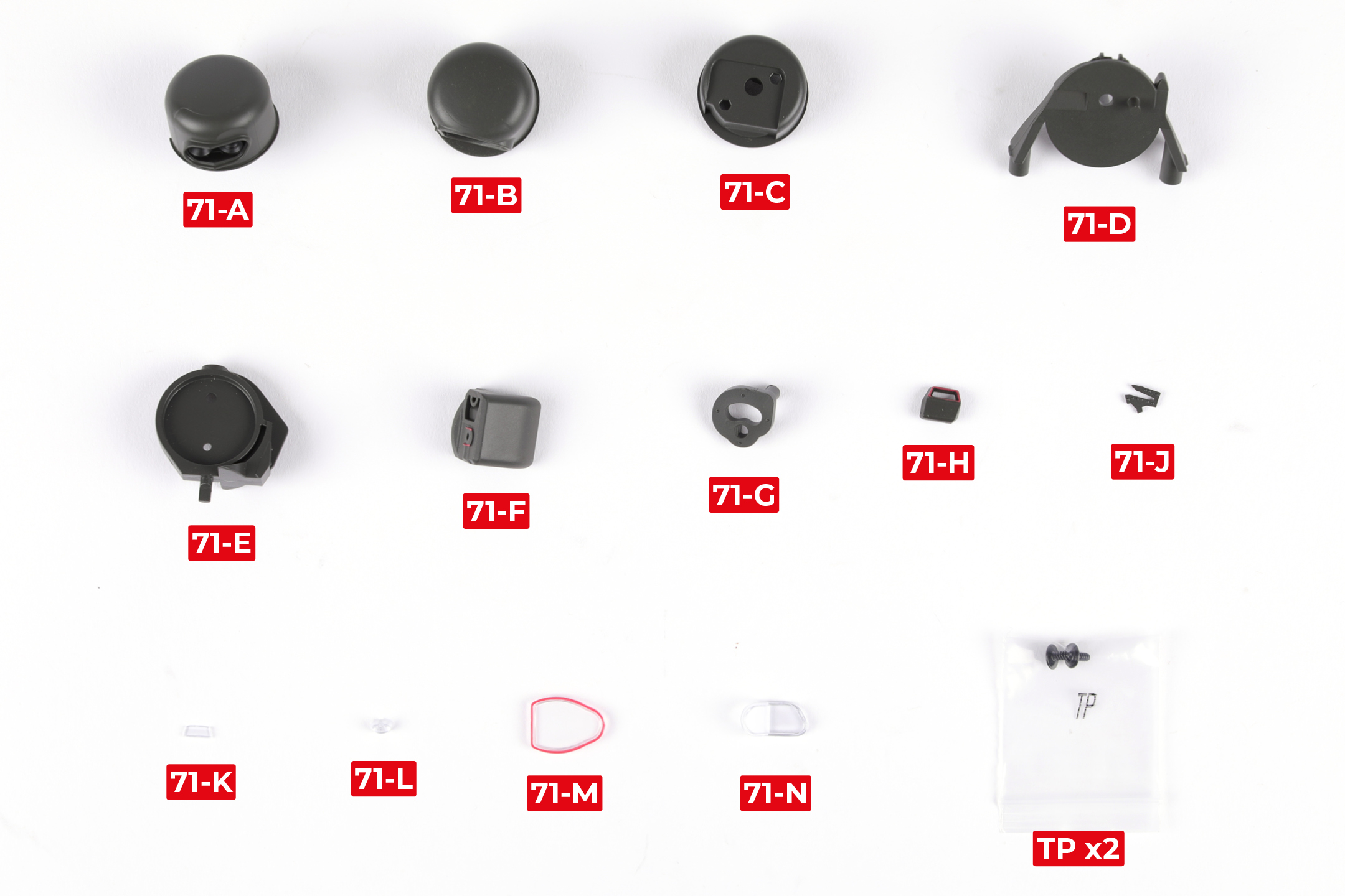
PARTS LIST
| 71-A | 71-F | 71-L |
| 71-B | 71-G | 71-M |
| 71-C | 71-H | 71-N |
| 71-D | 71-J | TP x2 |
| 71-E | 71-K |
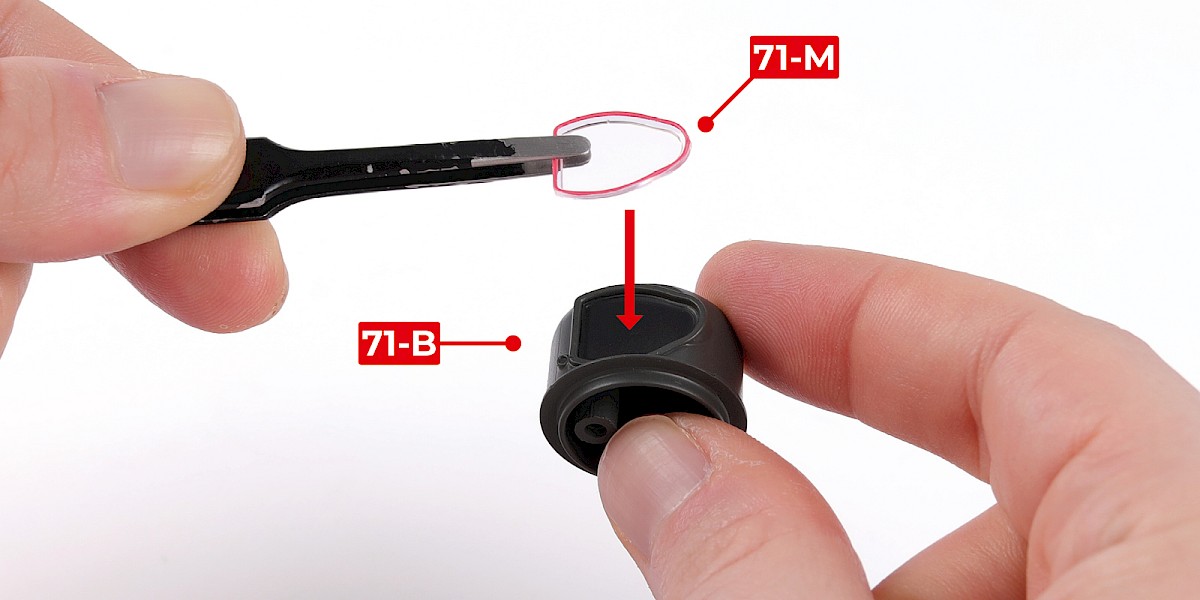
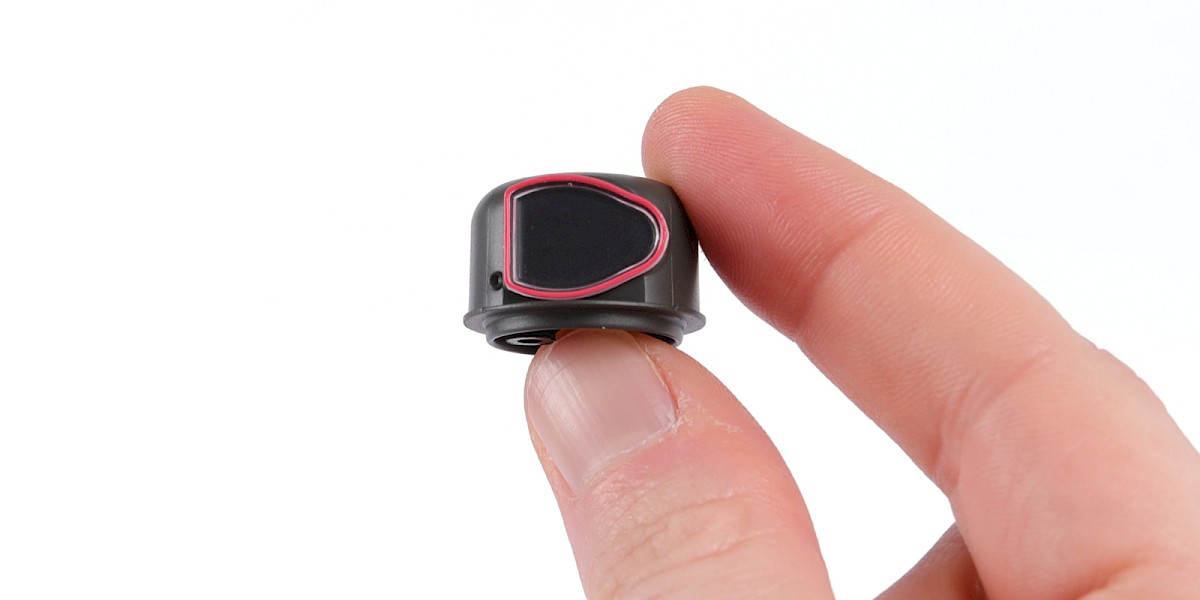
Step 1
Fit 71-M to 71-B.
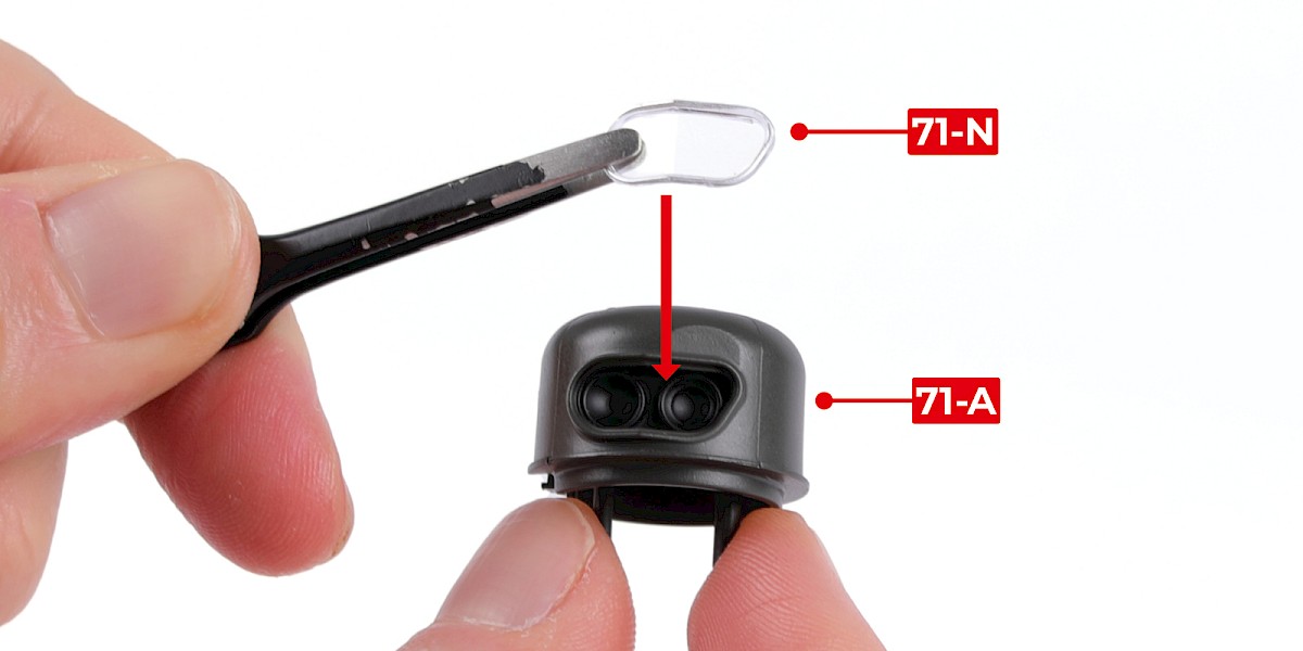
Step 2
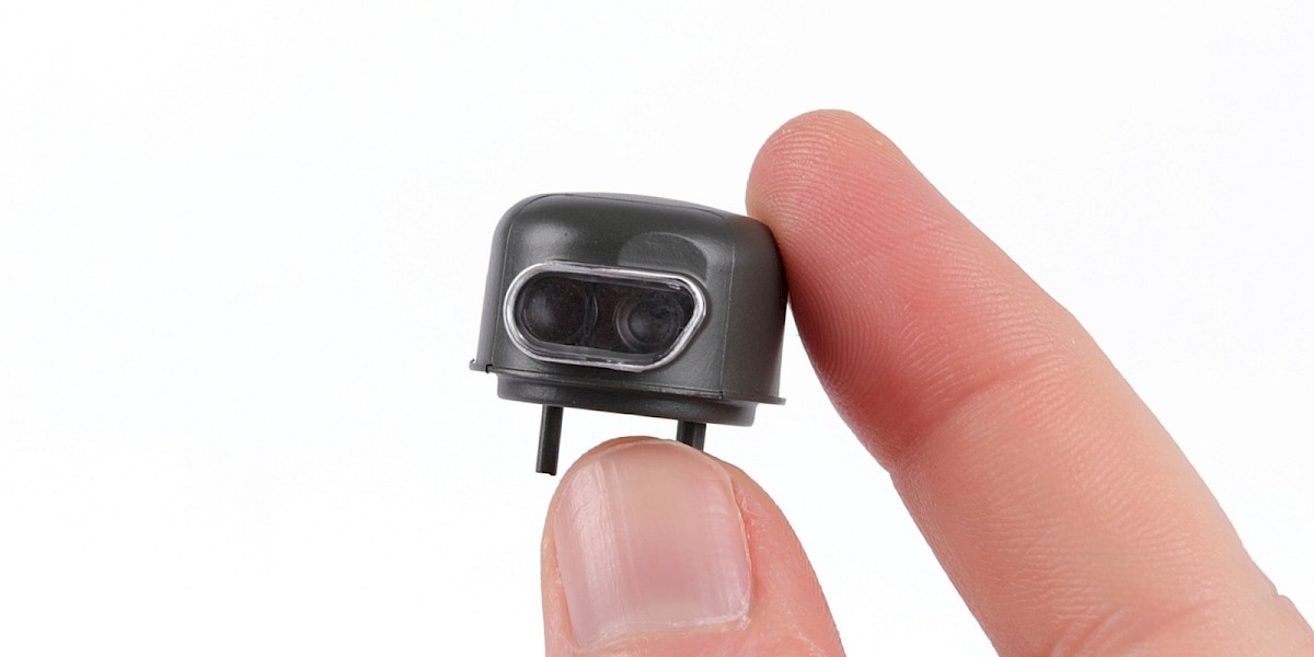
Fit 71-N to 71-A.
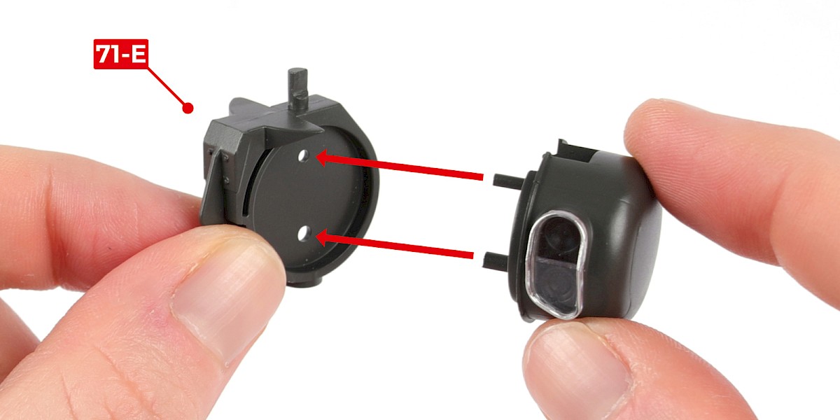
Step 3
Fit the assembly through 71-E.
Then fit the assembly from step 1 to the opposite side.
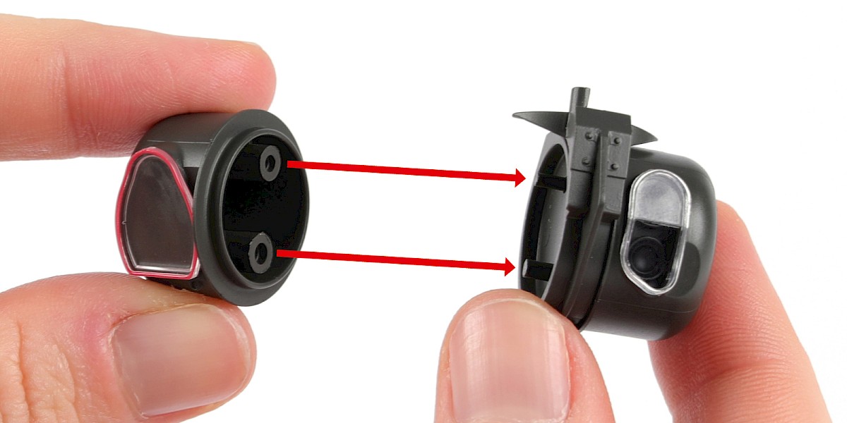
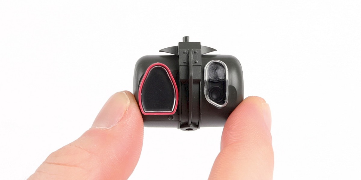
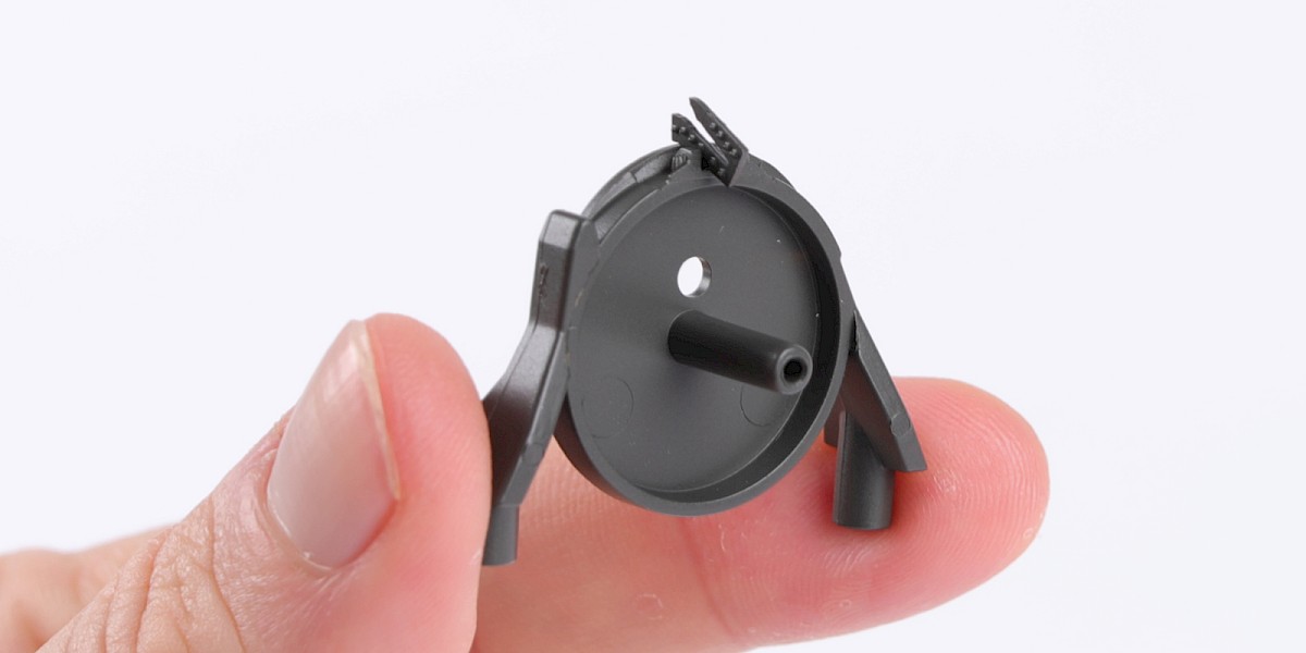
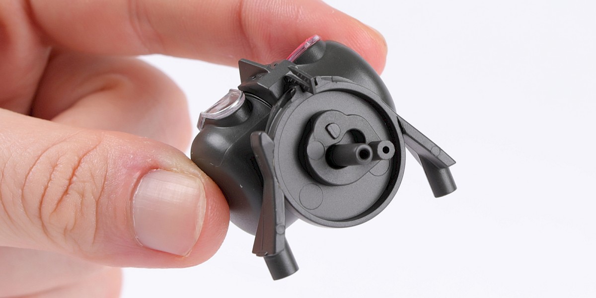
Step 4
The assembly should now look like this.
Step 5
Glue 71-J to 71-D.
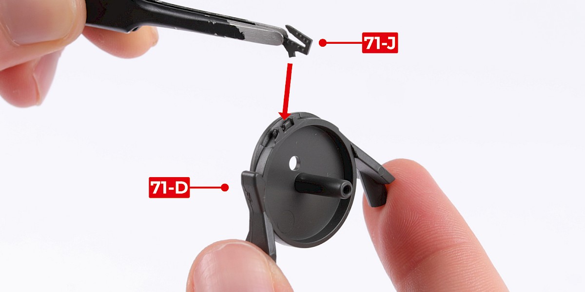
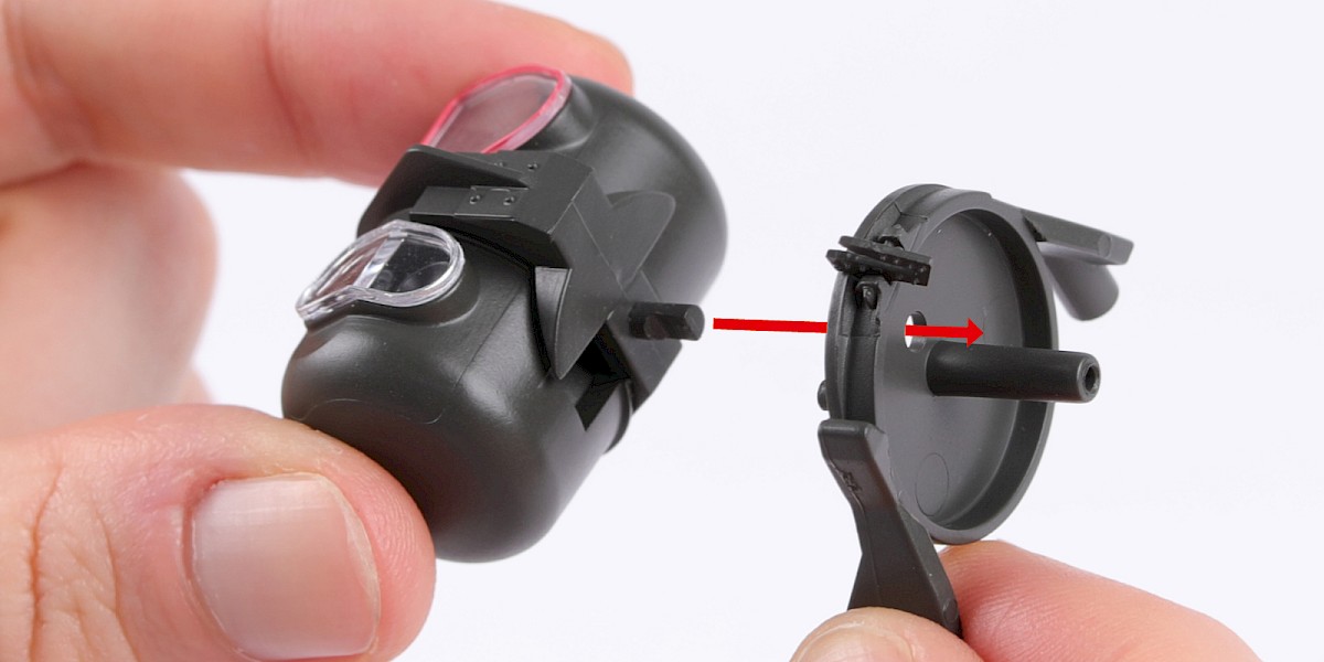
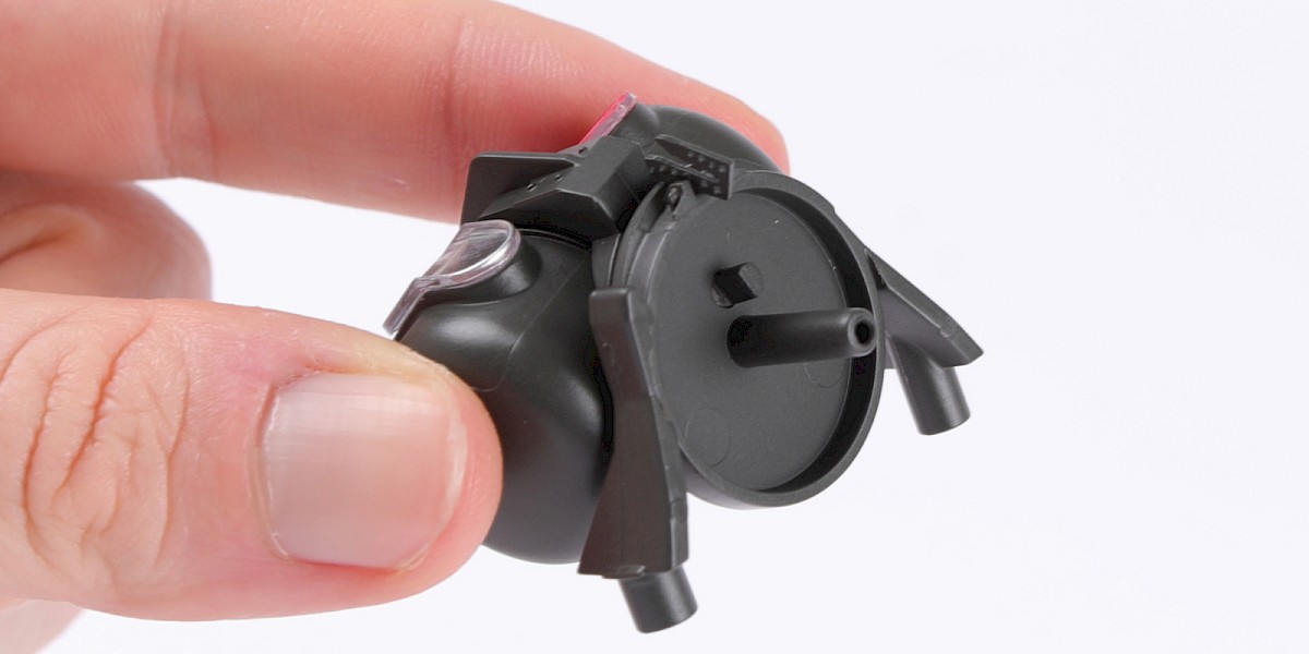
Step 6
Fit the two assemblies together as shown.
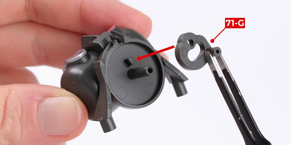
Step 7
Fit 71-G to the assembly.
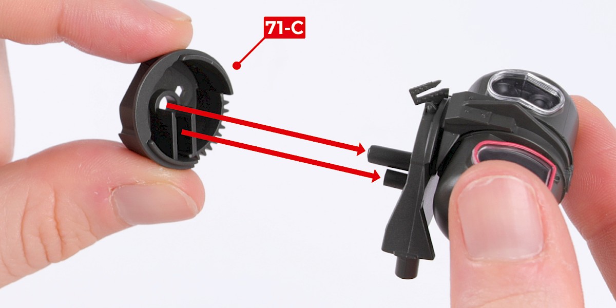
Step 8
Fit 71-C to the assembly. Make sure the parts are in the orientation shown.
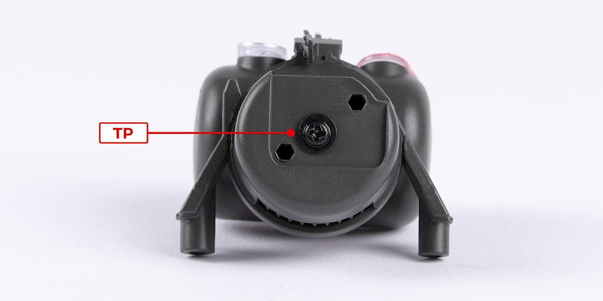
Step 9
Secure the parts together with 1x TP.
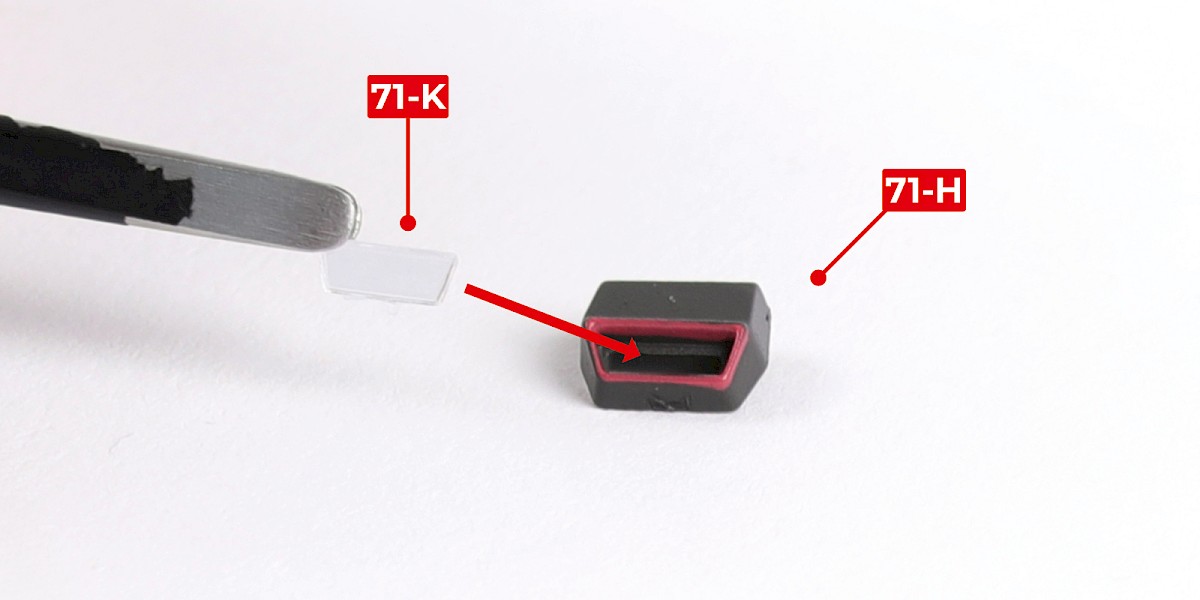
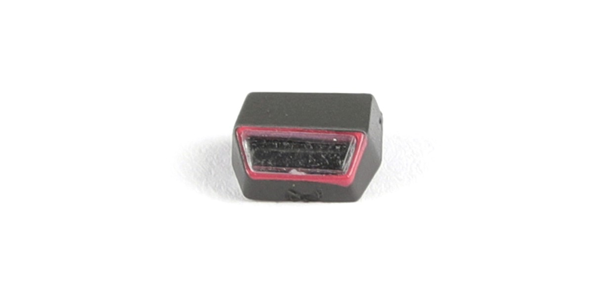
Step 10
Glue 71-K to 71-H. Use PVA glue.
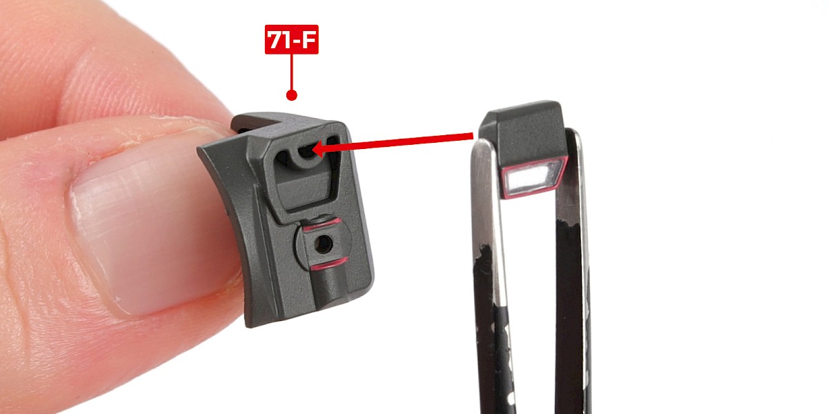
Step 11
Fit the assembly to 71-F.
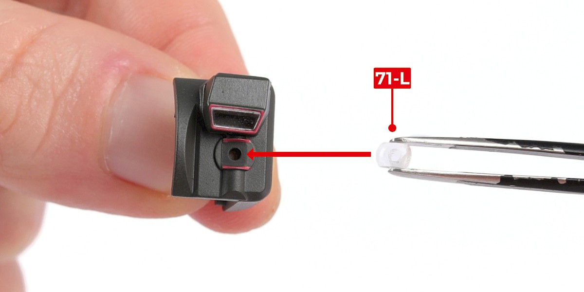
Step 12
Glue 71-L to the assembly. Use PVA glue.
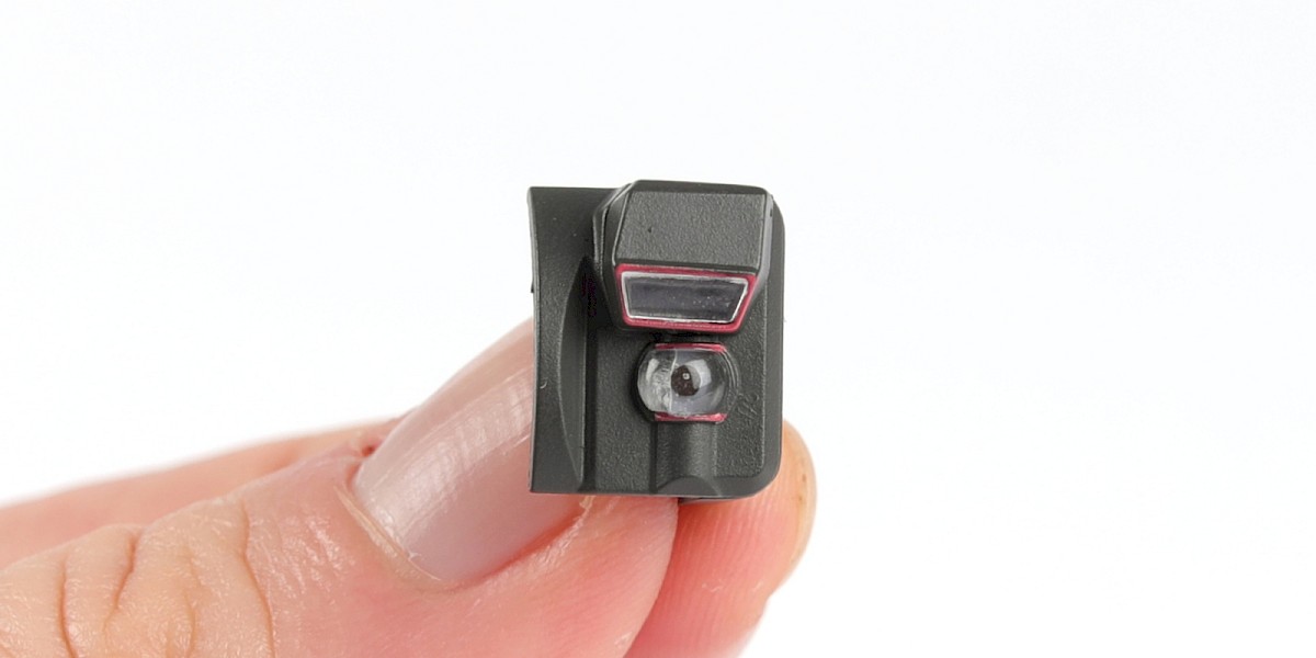
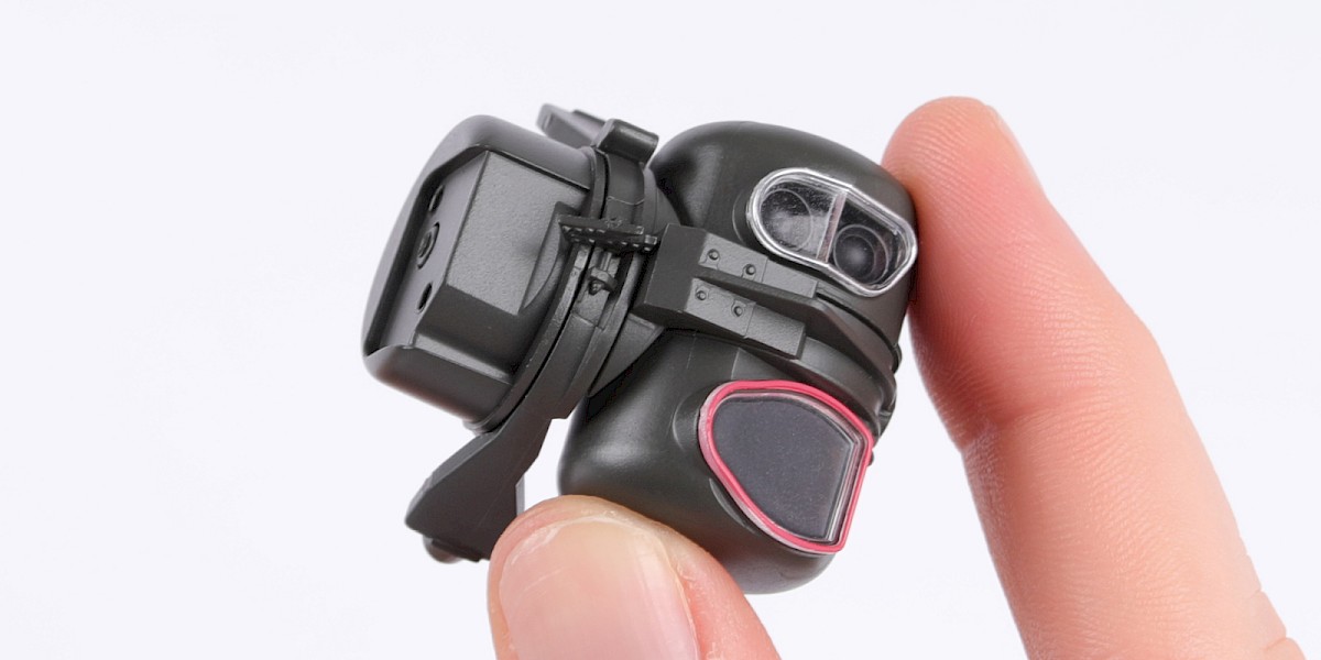
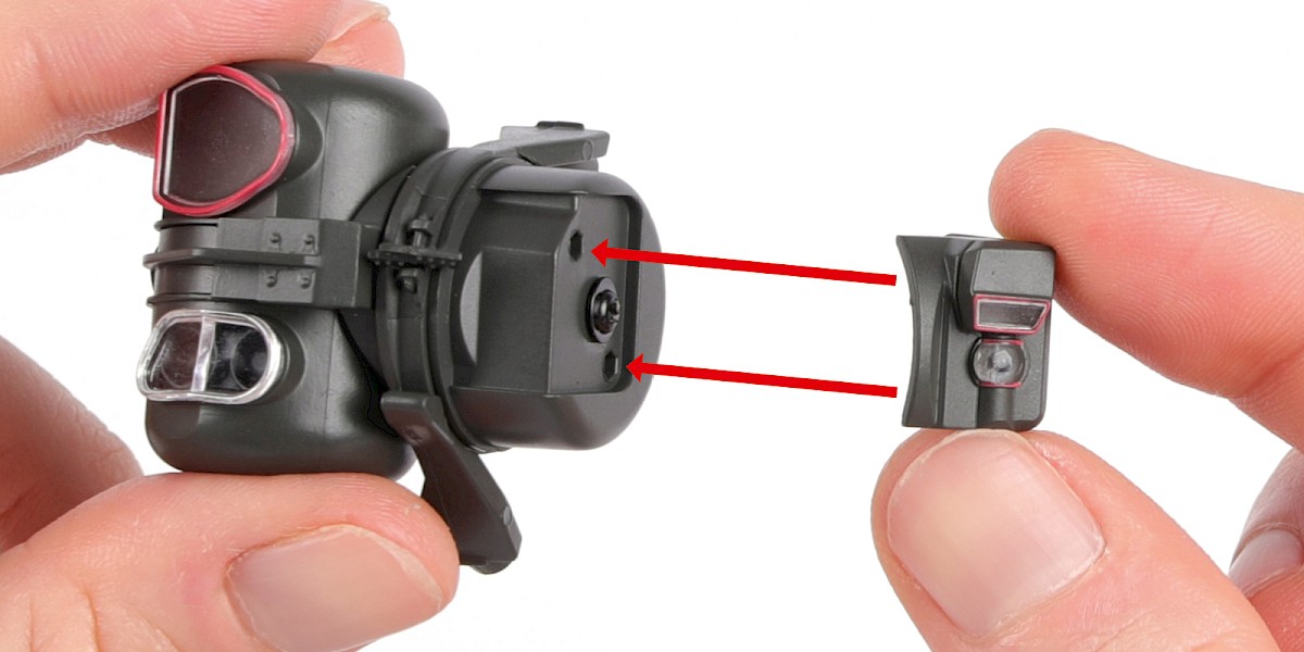
Step 13
Fit the two assemblies together as shown.
STAGE COMPLETE
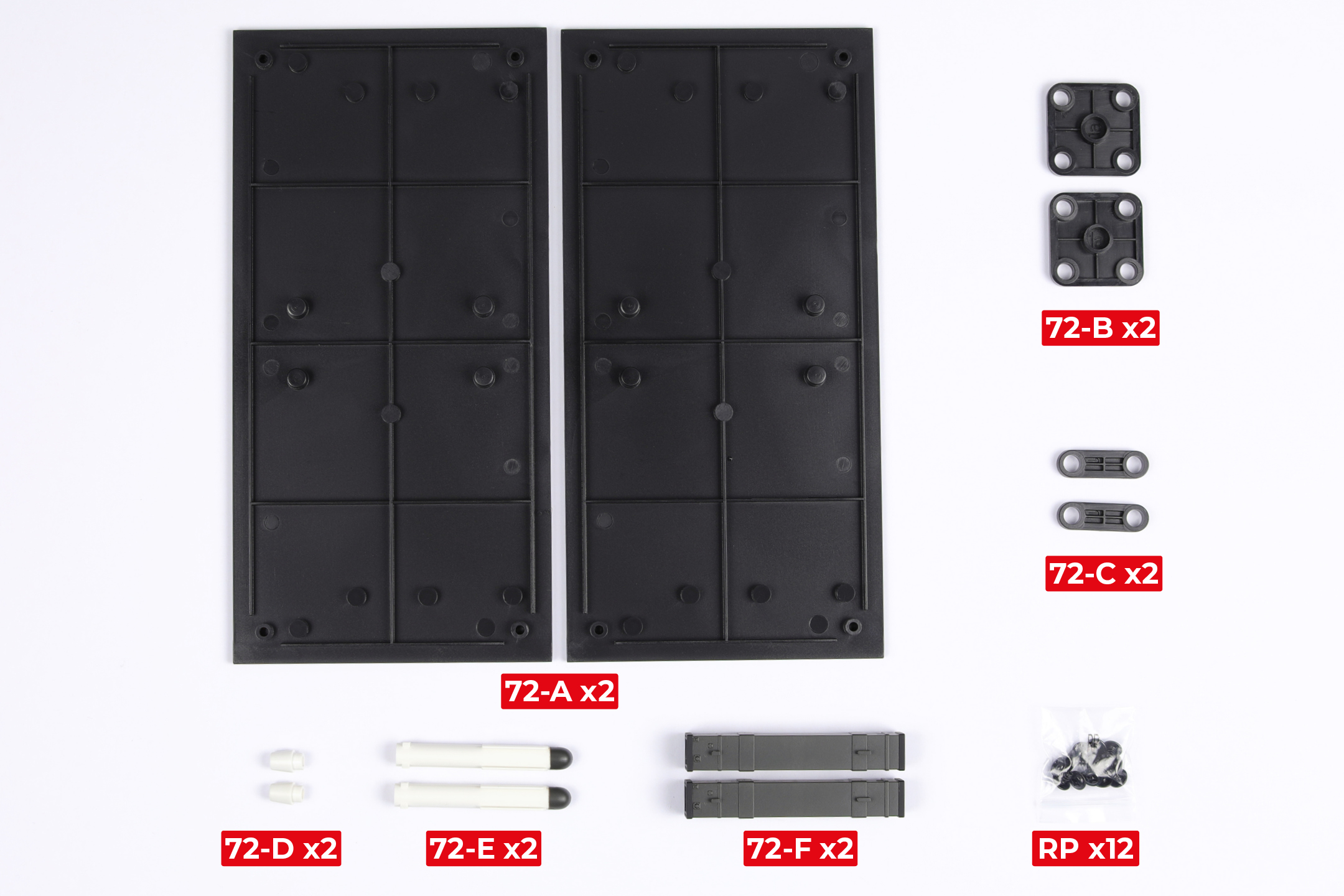
PARTS LIST
| 72-A x2 | 72-E x2 |
| 72-B x2 | 72-F x2 |
| 72-C x2 | RP x12 |
| 72-D x2 |
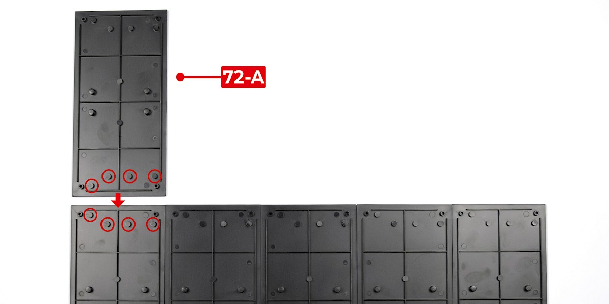
Step 1
Fit 72-A to the assembly from stage 69. Make sure 72-A is in the orientation shown.
Secure with 2x RP.
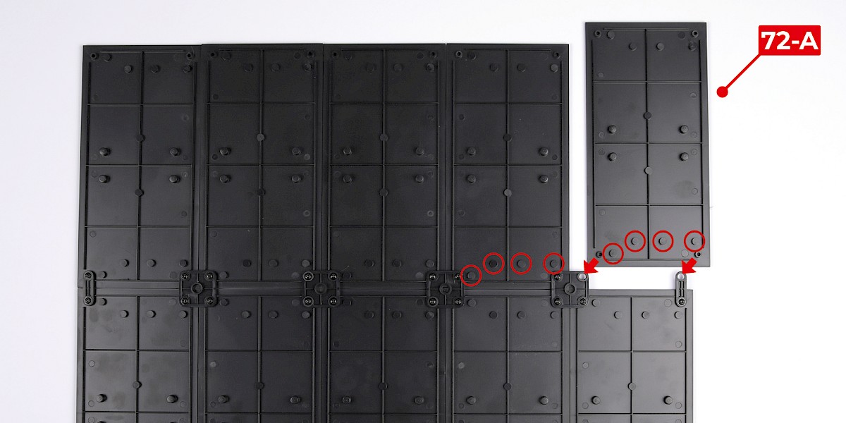
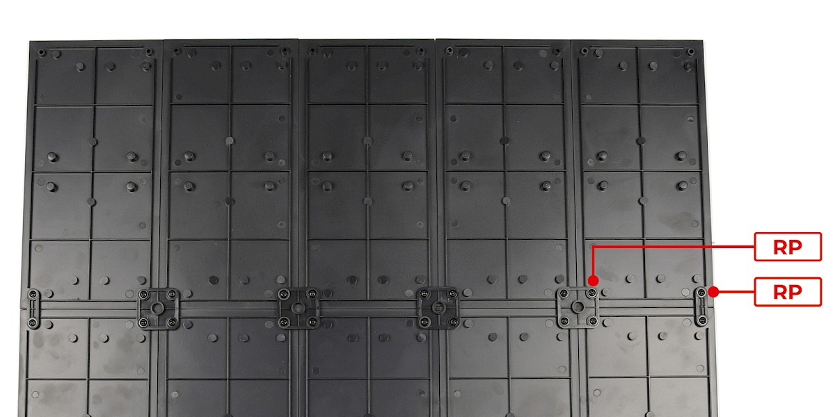
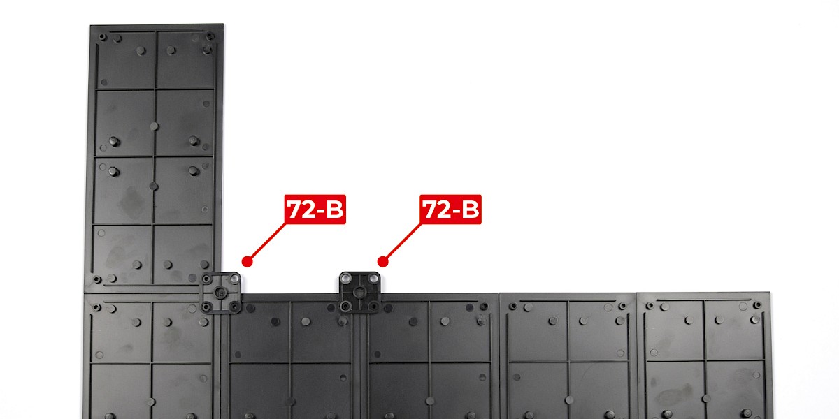
Step 2
Fit 72-A to the assembly. Make sure the parts are in the orientation shown.
Fit 72-B to the assembly.
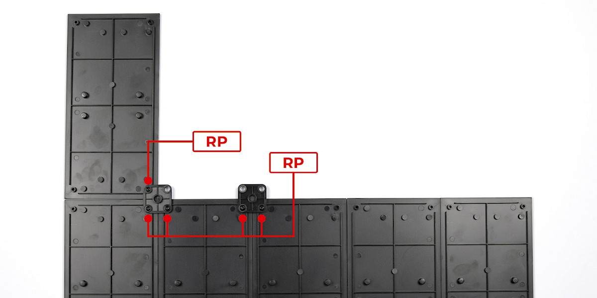
Step 3
Secure with 5x RP.
Step 4
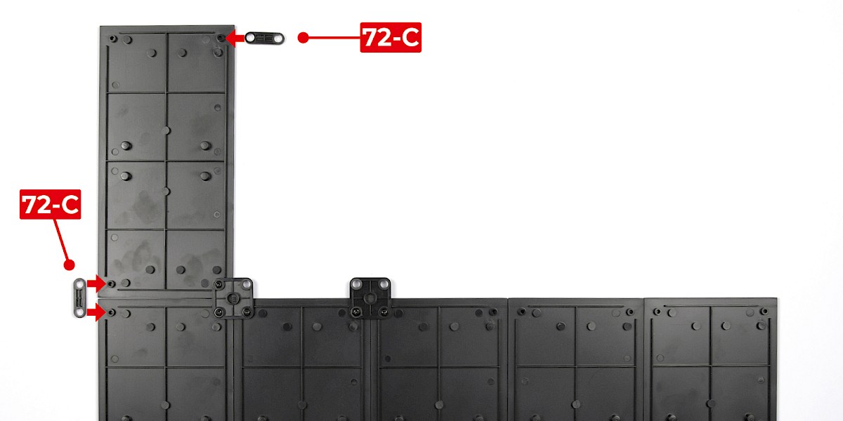
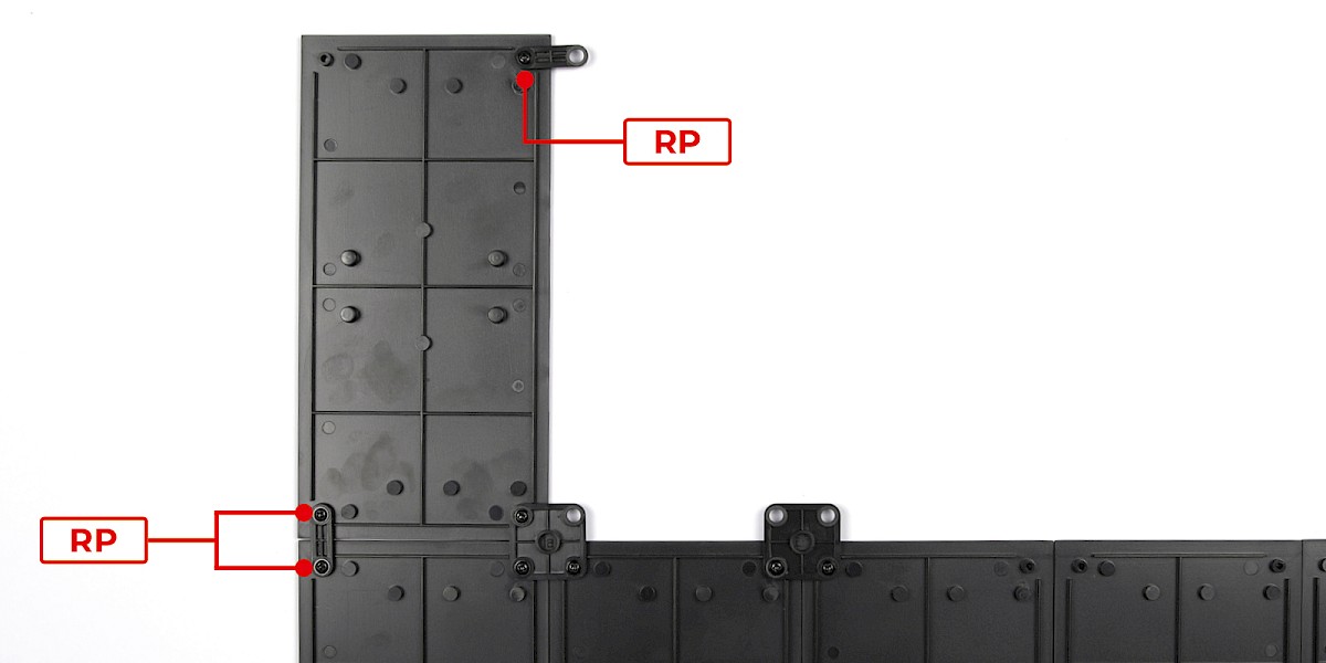
Fit 72-C to the assembly.
Secure with 3x RP.
Step 5
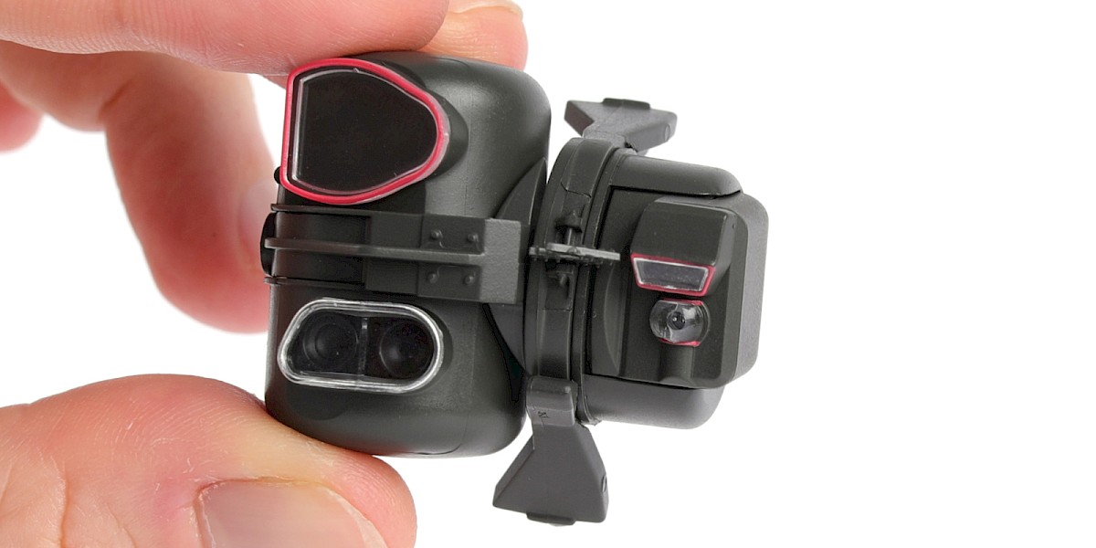
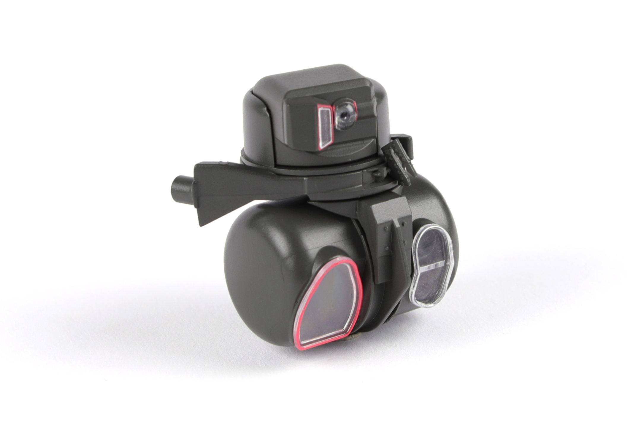
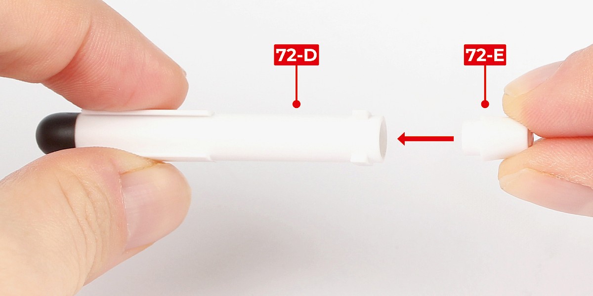
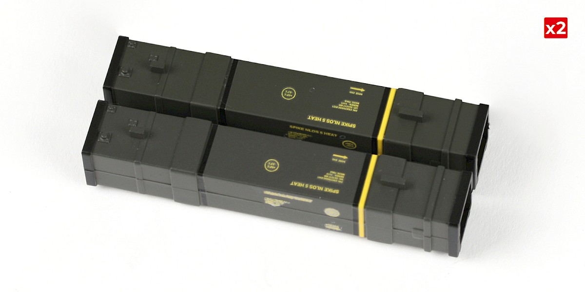
You will now build the Spike missiles and their containers.
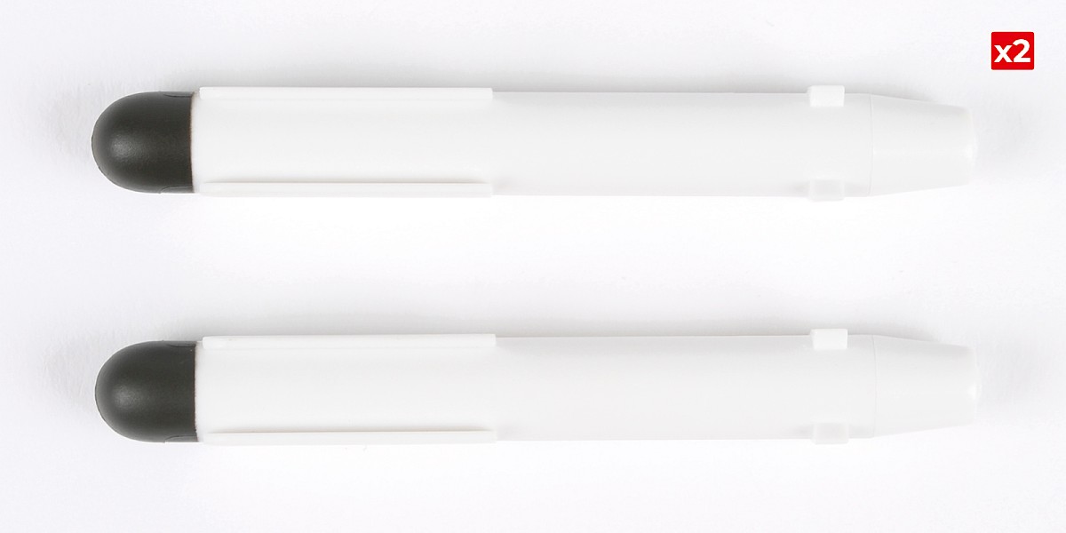
Fit 72-E into 72-D.
Repeat this process to assemble the second missile.
Step 6
Cut the decals outlined in red from 67-F.
Step 7
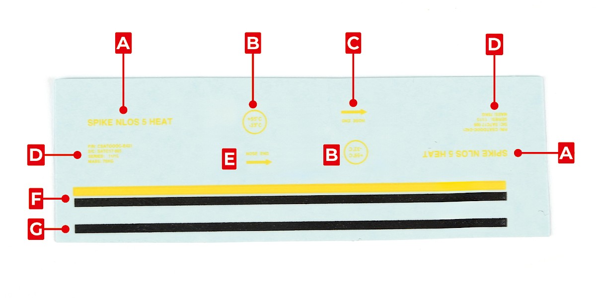
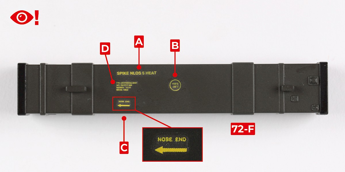
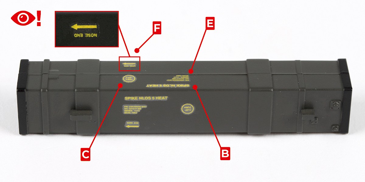
Apply decals A, B, C and D to 72-F.
Pay attention to decal C. The arrow should point left, with the text above the arrow.
Step 8
Turn the assembly on its side with the previous set of decals facing you.
Apply decals A, B, D and E to 67-F. Note that these decals are applied with the text upside-down.

Step 9
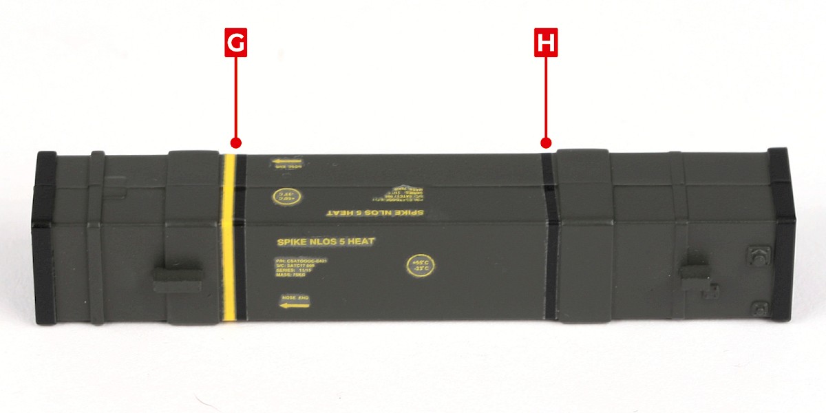
Apply decals F and G to 67-F.
Repeat this process on the second missile container.

STAGE COMPLETE
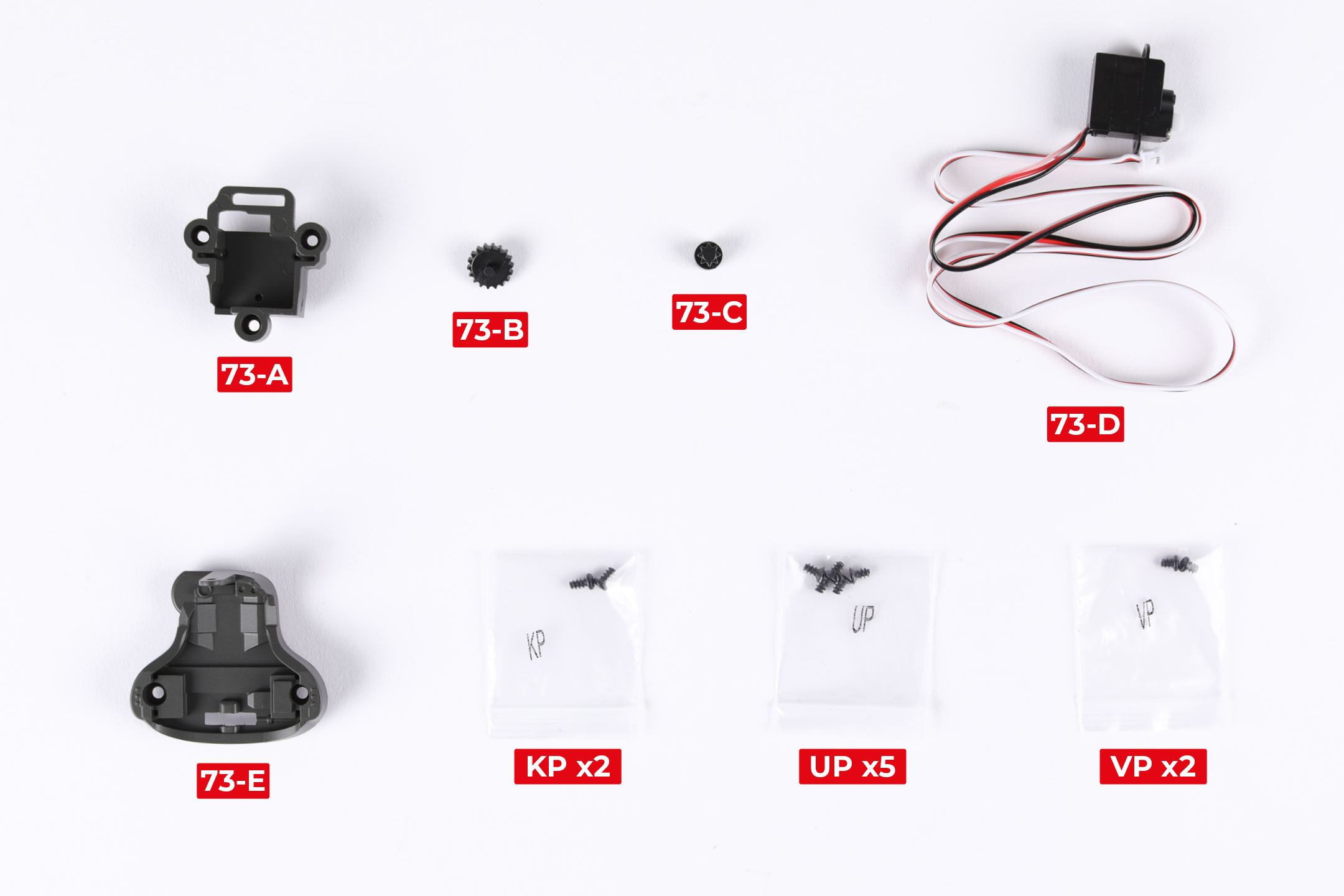
PARTS LIST
| 73-A | 73-E |
| 73-B | KP x2 |
| 73-C | UP x5 |
| 73-D | VP x2 |
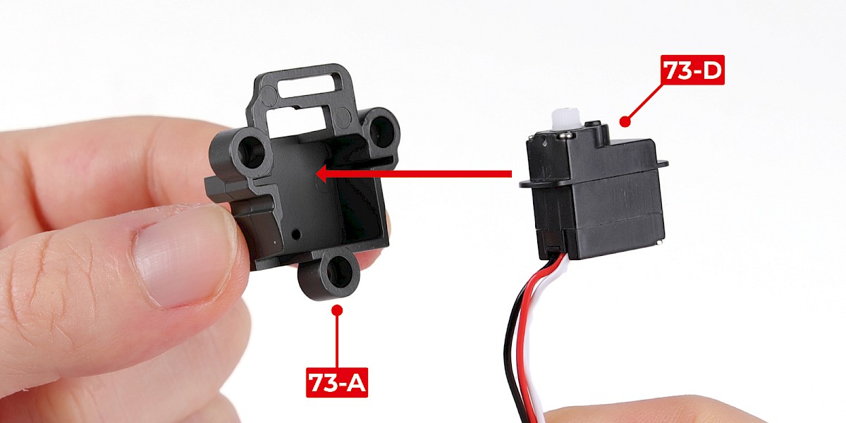
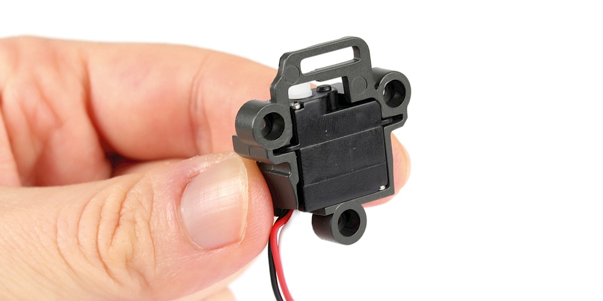
Step 1
Fit 73-D to 73-A.
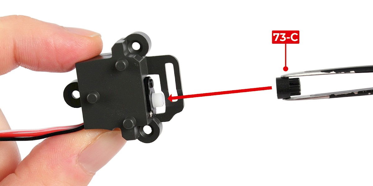
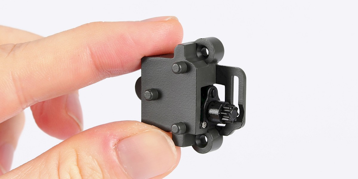
Step 2
Fit 73-C to the assembly.
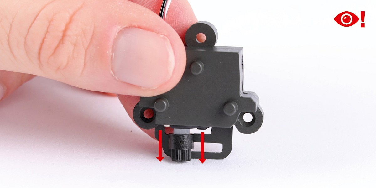
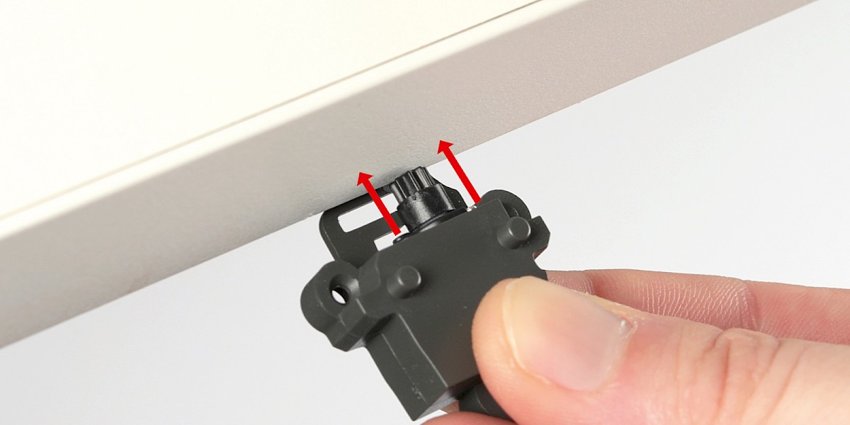
Step 3
You may find it easier to press the assembly down onto 73-C using the surface and edge of your work table.
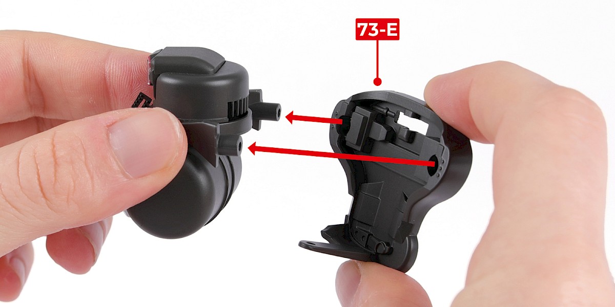
Step 4
Fit 73-E to the assembly from stage 71.
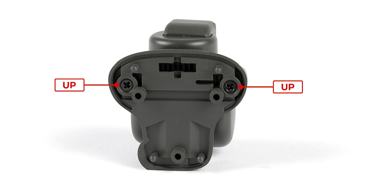
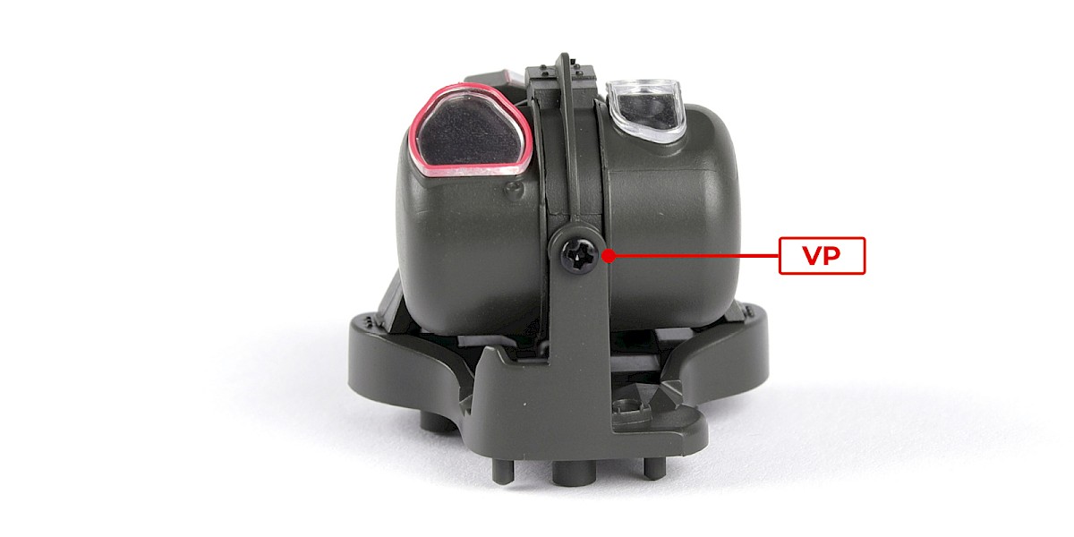
Step 5
Secure with 2x UP and 1x VP.
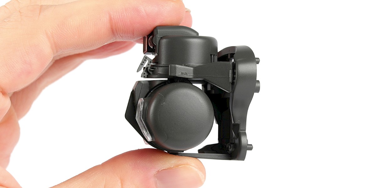
Step 6
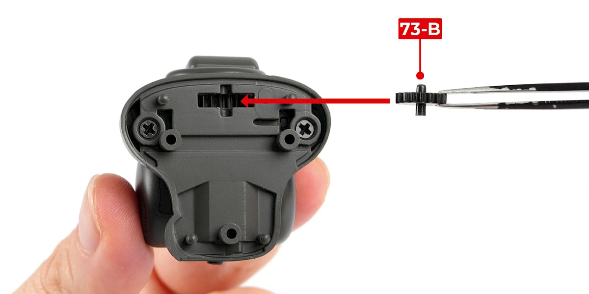
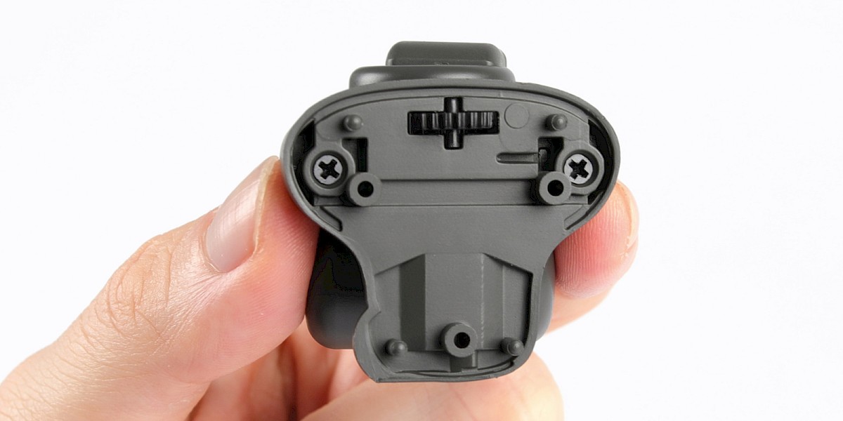
Fit 73-B to the assembly.
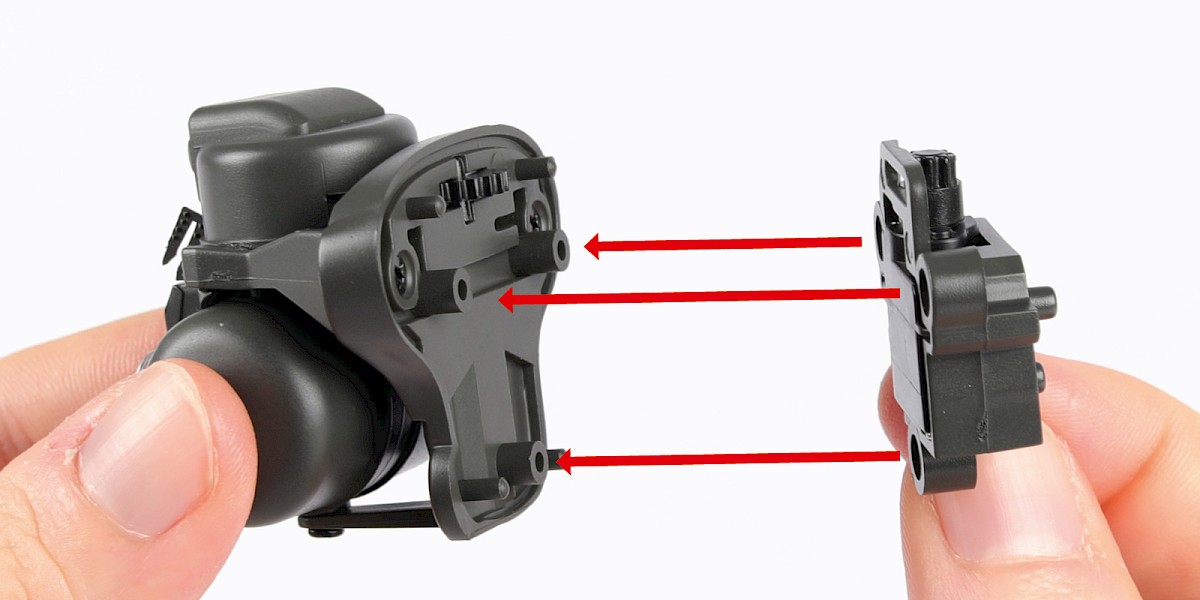
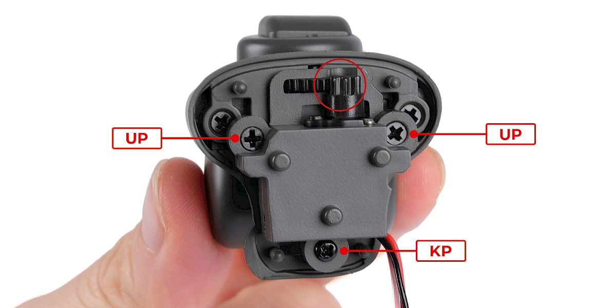
Step 7
Fit the two assemblies together. Make sure the teeth of the gears connect.
Secure with 2x UP and 1x KP.
STAGE COMPLETE
PARTS LIST
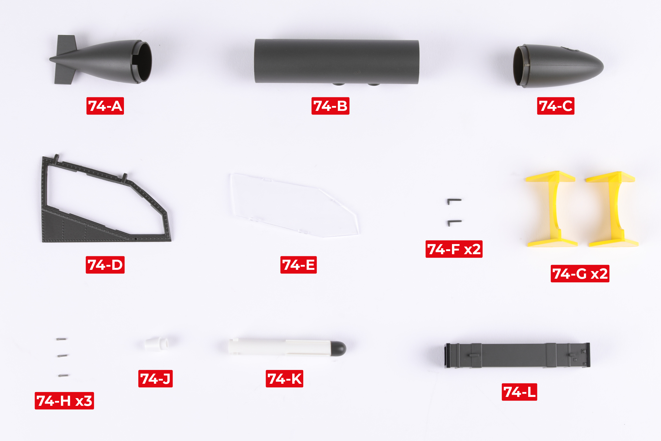
| 74-A | 74-G x2 |
| 74-B | 74-H x3 |
| 74-C | 74-J |
| 74-D | 74-K |
| 74-E | 74-L |
| 74-F x2 |
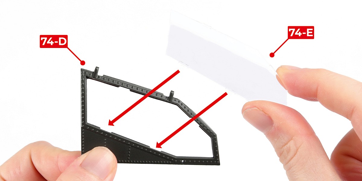
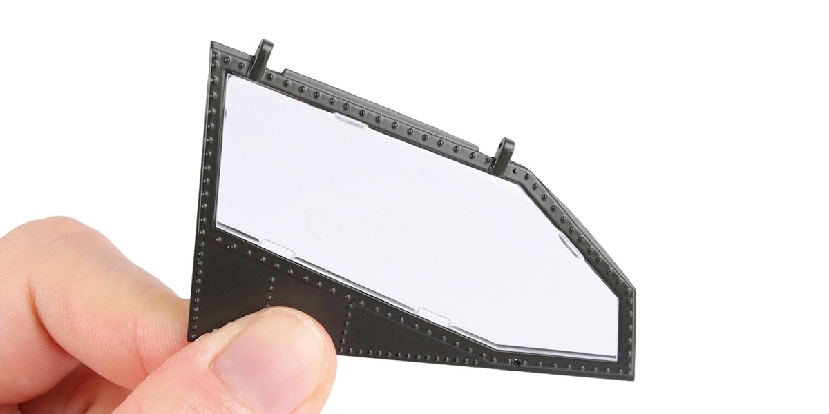
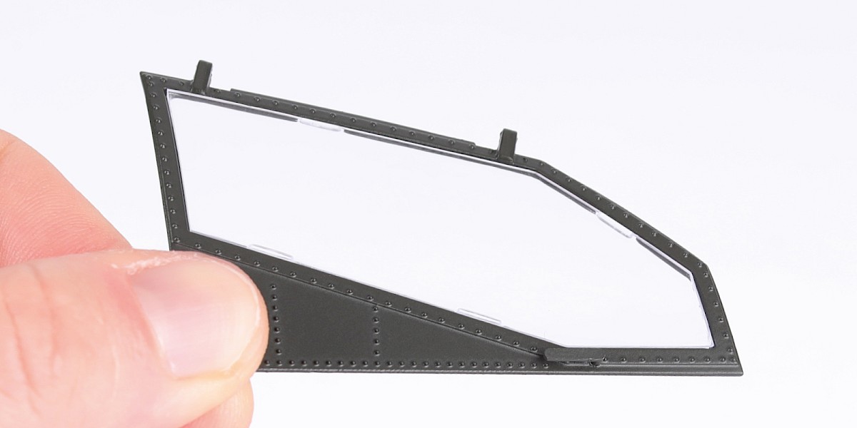
Step 1
Fit 74-E to 74-D.
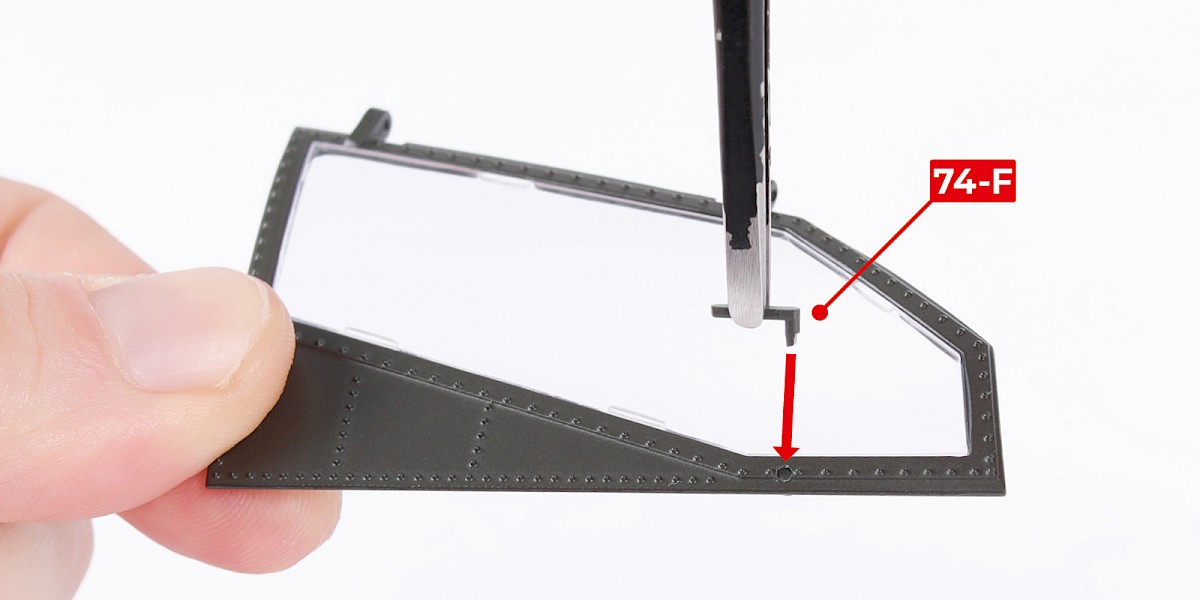
Step 2
Glue 74-F to the assembly.
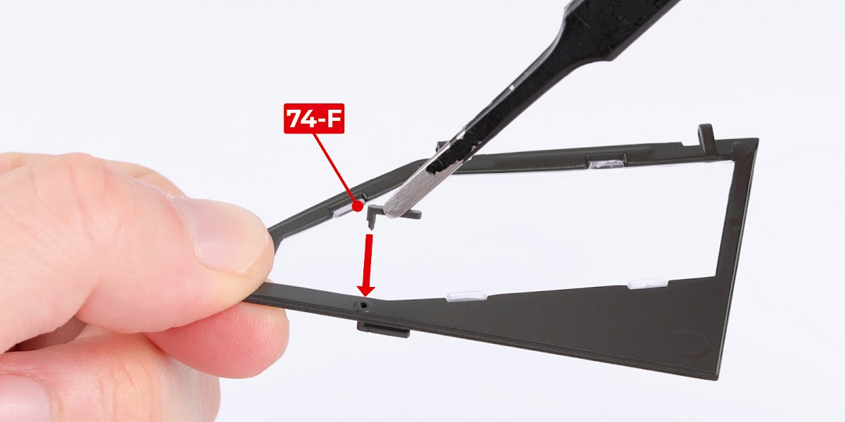
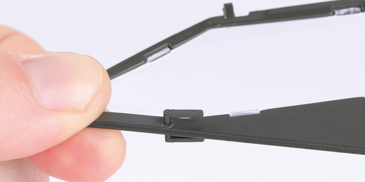
Step 3
Glue another 74-F to the opposite side as shown.
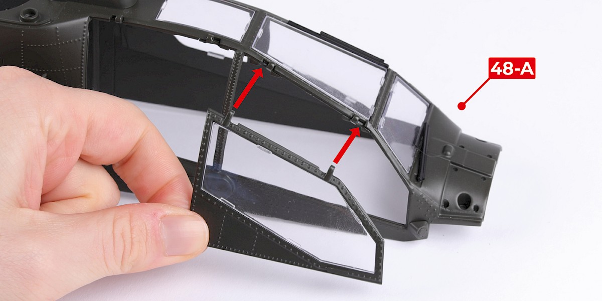
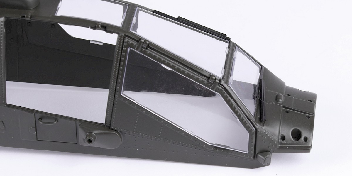
Step 4
Fit the assembly to 48-A.
Step 5
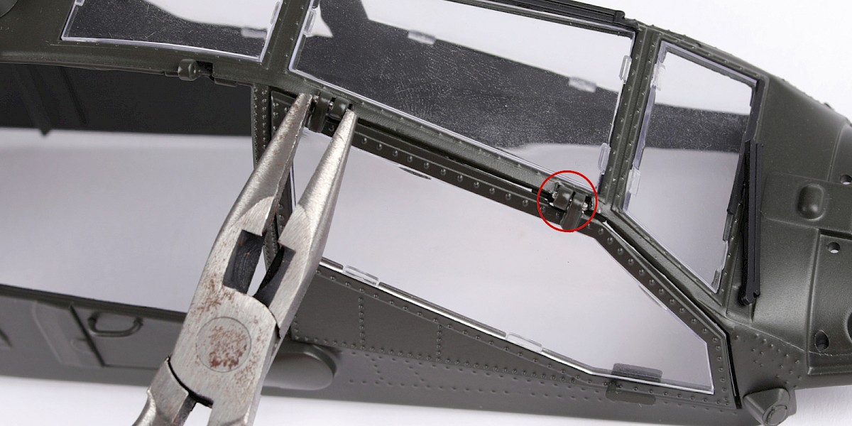
Insert 74-H with the smooth end first, as shown.
Repeat for the other hinge.
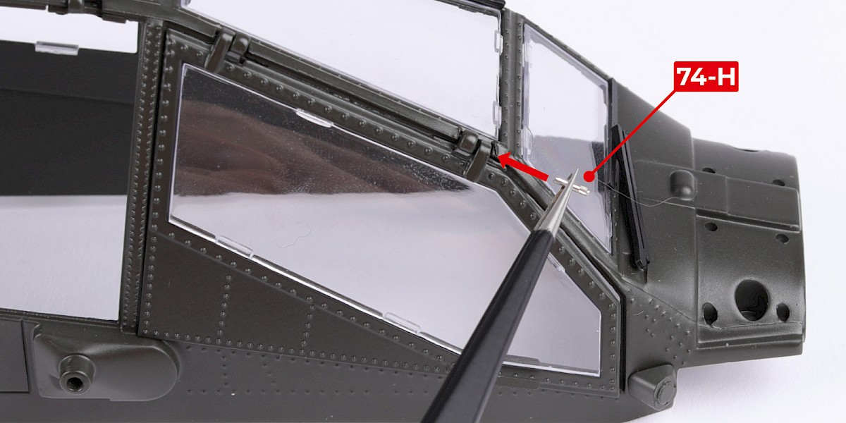
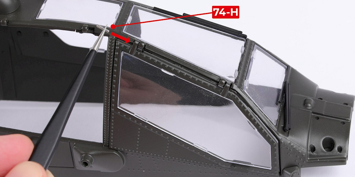
Step 6
Use pliers to press the parts into place.
Step 7
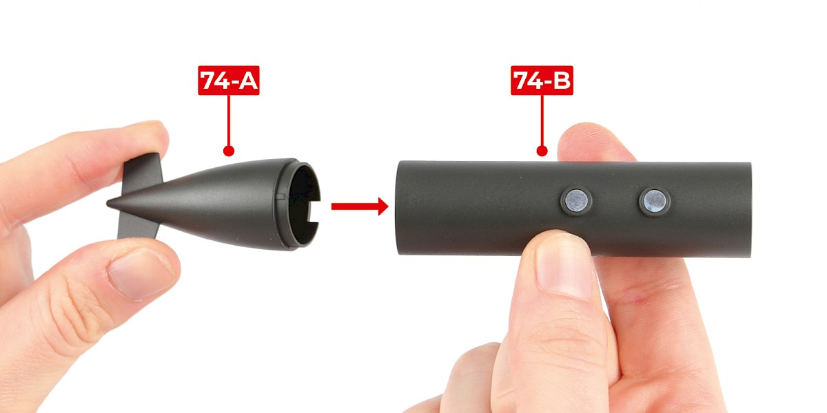
You will now build an external fuel tank.
Fit 74-A to 74-B.
Step 8
Fit 74-C to the assembly.


Step 9
Cut the decal outlined in red from 67-F.
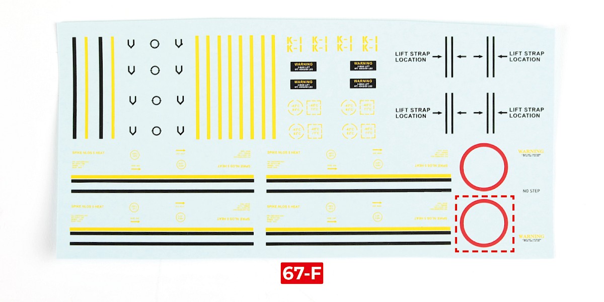
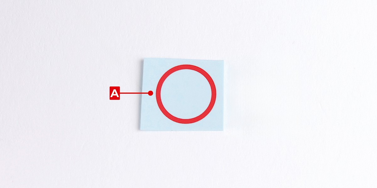
Step 10
Apply decal A to the fuel tank.
The fuel tank can be displayed on the racks (74-G).

Step 11
You will now build the Spike missile and its container.
Fit 74-J into 74-K.

Step 12
Cut the decals outlined in red from 67-F.
Step 13
Apply decals B, C, D E and F to 74-L.

Step 14
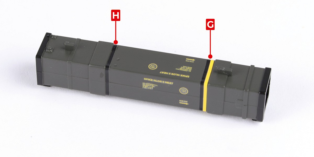
Apply decals G and H to 74-L.
Step 15
Take the remaining container from stage 31. Apply decals G and H.
STAGE COMPLETE
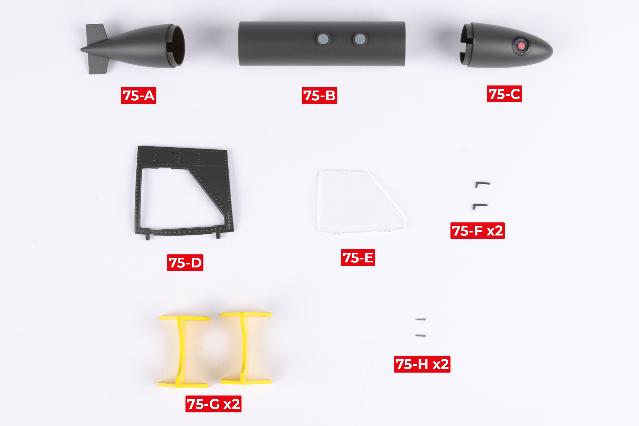
PARTS LIST
| 75-A | 75-E |
| 75-B | 75-F x2 |
| 75-C | 75-G x2 |
| 75-D | 75-H x2 |
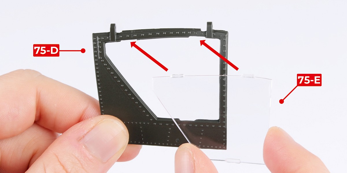
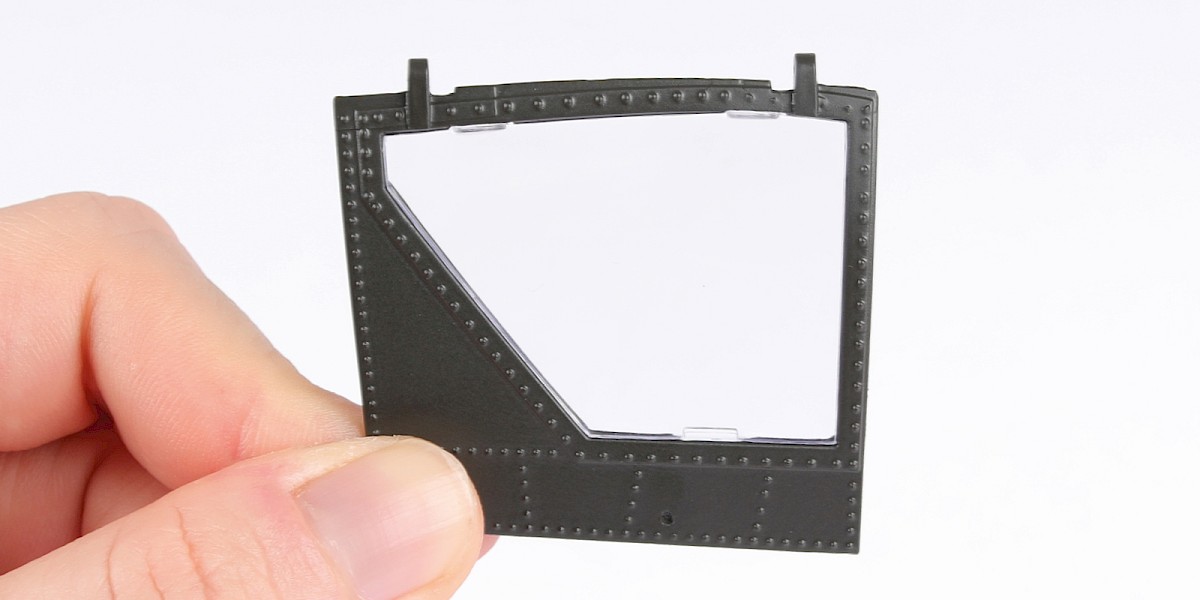
Step 1
Fit 75-E to 75-D.
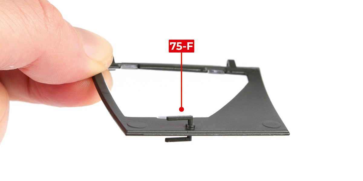
Step 2
Glue 75-F to the assembly.
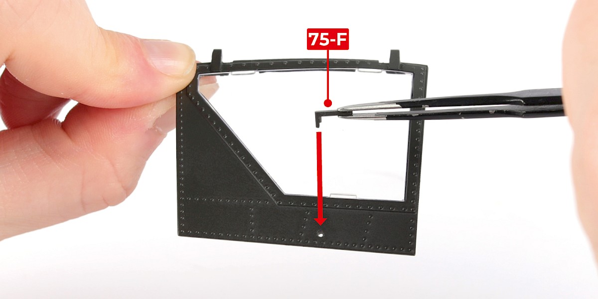
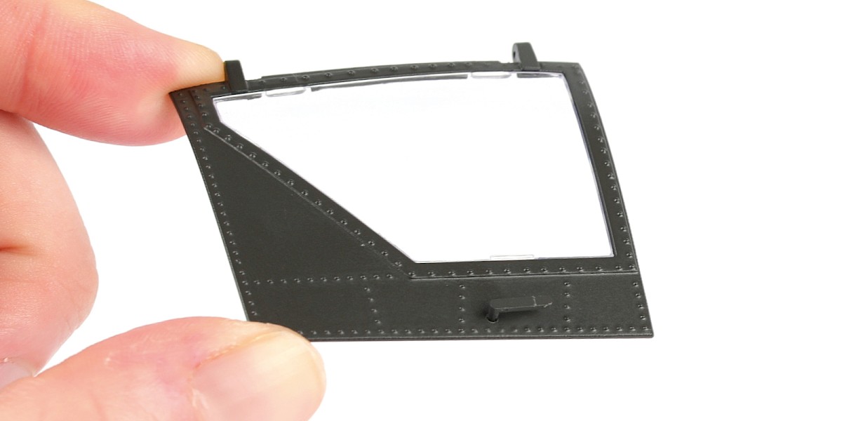
Step 3
Glue another 75-F to the opposite side.
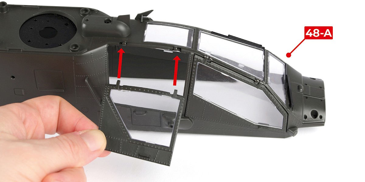
Step 4
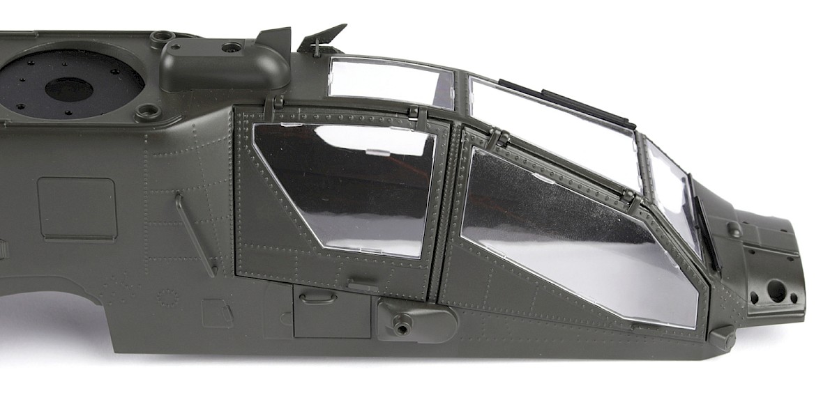
Fit the assembly to 48-A.
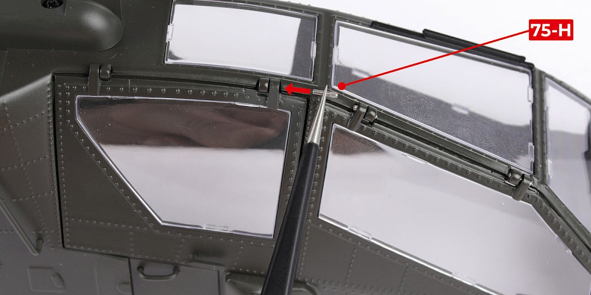
Step 5
Insert 75-H with the smooth end first, as shown.
Repeat for the other hinge.

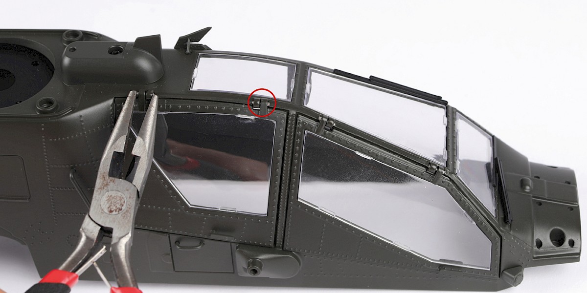
Step 6
Use pliers to press the parts into place.
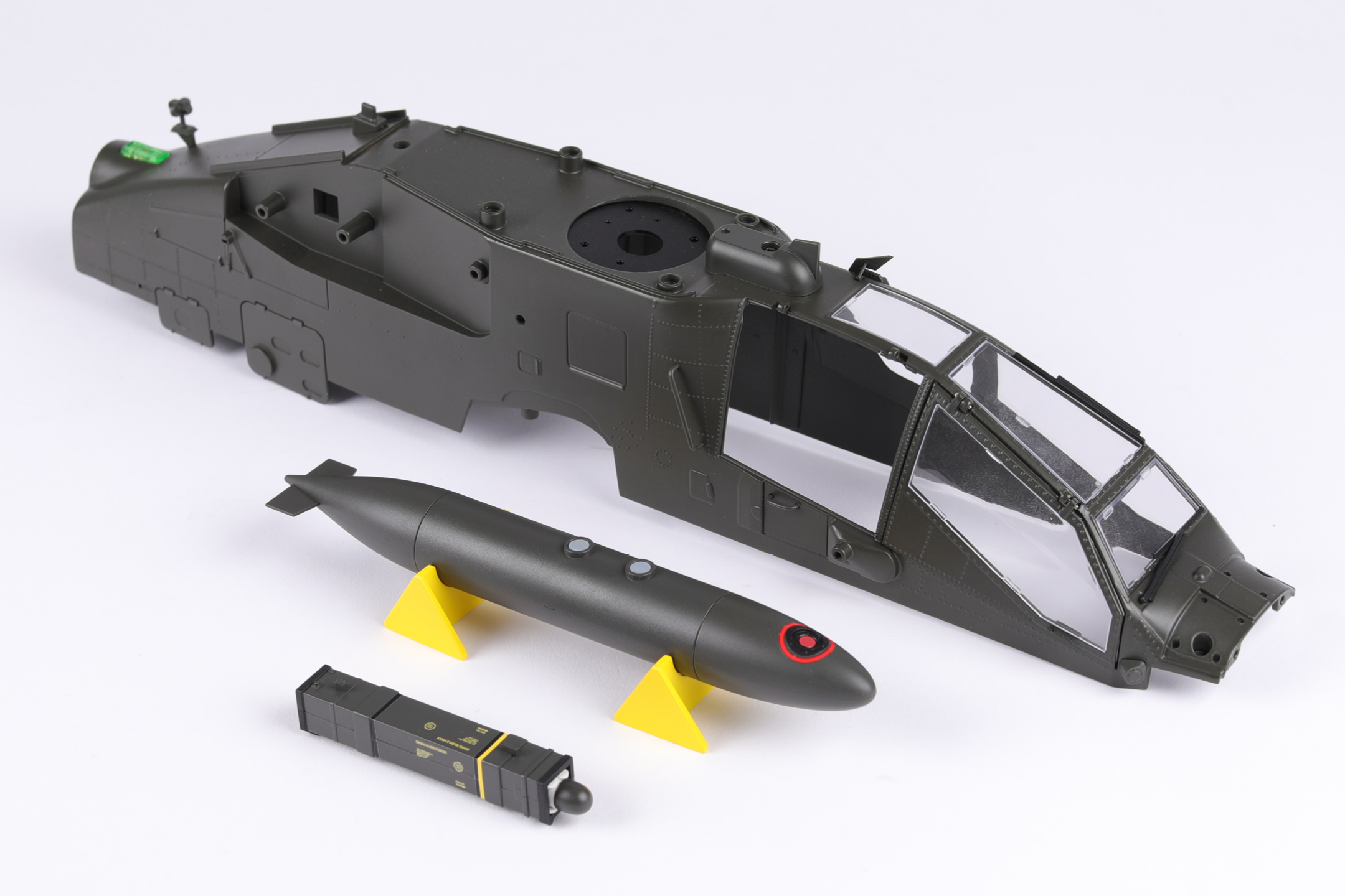
Step 7
You will now build the fuel tank.
Fit 75-A to 75-B.

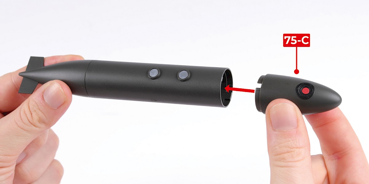
Step 8
Fit 75-C to the assembly.
Step 9
Cut the decal outlined in red from 67-F.

Step 10
Apply decal A to the fuel tank.
The fuel tank can be displayed on the racks (75-G).
STAGE COMPLETE