Pack 01
BUILD INSTRUCTIONS
Instructions for building your Cutty Sark model ship
Your model of the Cutty Sark is divided into 12 packs.
You will need to follow the step-by-step assembly photos, the plans and the explanatory texts below.
Please save the leftover materials from each pack for use when instructed to do so at a later stage of the assembly instructions.
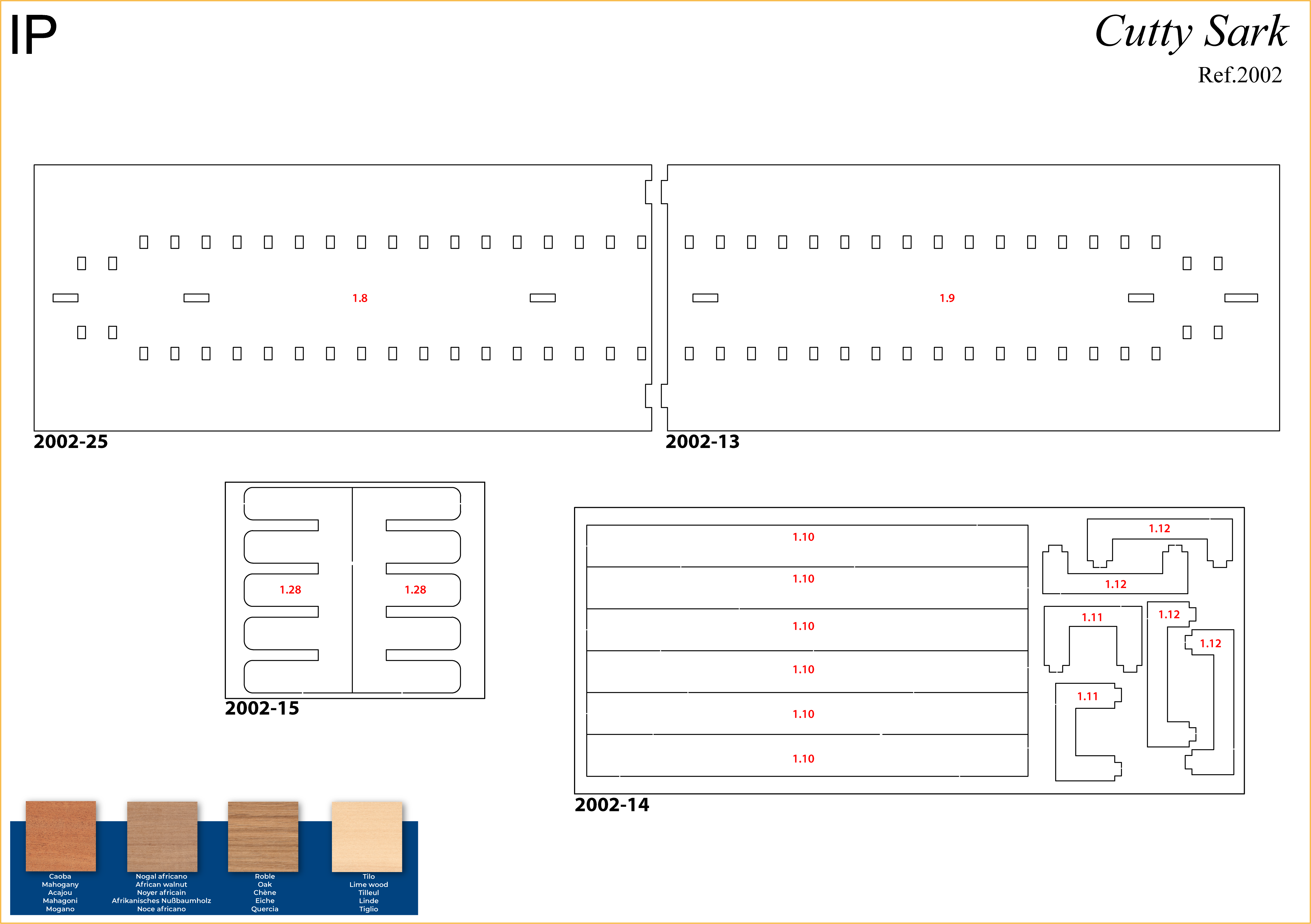
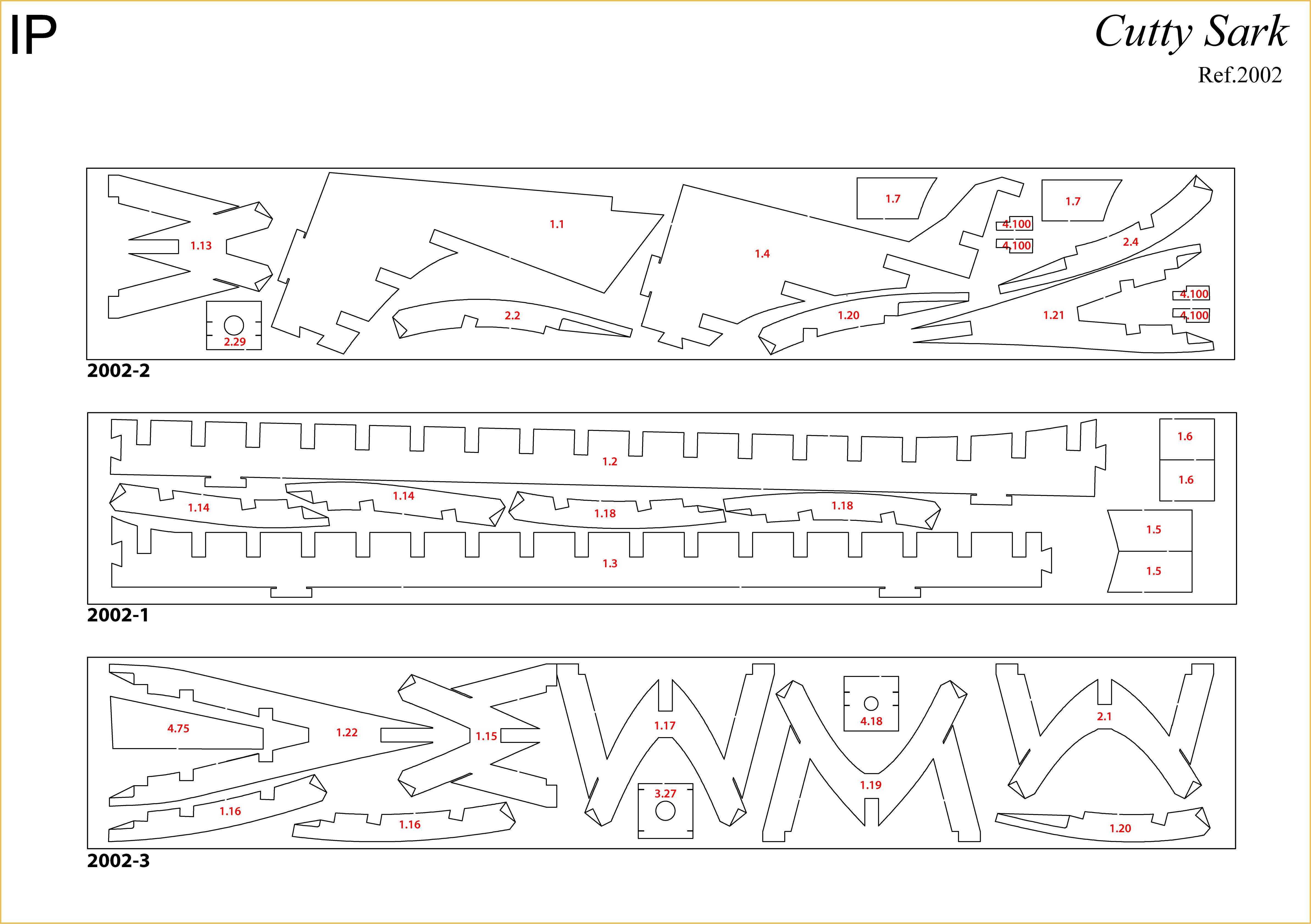
The IP sheets displayed below are drawings of laser-cut parts and photo-etched brass parts and will serve as a guide for identification of some parts.
Use the PARTS REFERENCE table to help locate the parts.
The PL-00 templates (printed at 1/1 scale) included in each pack will serve as a guide for building the frames.
Please check the list below to ensure you have all the tools required for building your wooden ship.
When removing a part, cut the ribs that join the part to the wooden plate with a cutter.
Remove the parts carefully so as not to break them.
Keep and store the parts in their frames. Only remove the parts you are working on in each step.
Extra support can be found on our forum or from the Expert Directory page of our website.
PARTS LIST
| Material | Quantity | |
| Wooden Boards | ||
| 2002-1, 2002-2, 2002-3 | Wood | 3 |
| 2002-13, 2002-14, 2002-15 | Wood | 3 |
| 2001-25 | Wood | 1 |
| Wooden Strips | ||
| 5 x 5 x 400 mm | Oak | 9 |
| 3 x 3 x 400 mm | Lime wood | 6 |
| 2 x 3 x 600 mm | Lime wood | 15 |
| Wooden Rods | ||
| ø8 mm x 400 mm | Mahogany | 1 |
| Tools | ||
| Paintbrush No. 4 | 1 | |
| Paintbrush No. 8 | 1 | |
| Paintbrush No. 12 | 1 | |
| Satin varnish | 2 | |
| Templates | ||
| Assembly template PL-01 | 1 |
Useful tools for building this model: cutting mat, pencil, cutting knife, fine-grit sandpaper or sponge sandpaper, file, white wood glue, super glue (cyanoacrylate glue), masking tape, set square, hacksaw, sanding block, 30 cm steel ruler, clamps, moulding scriber tool
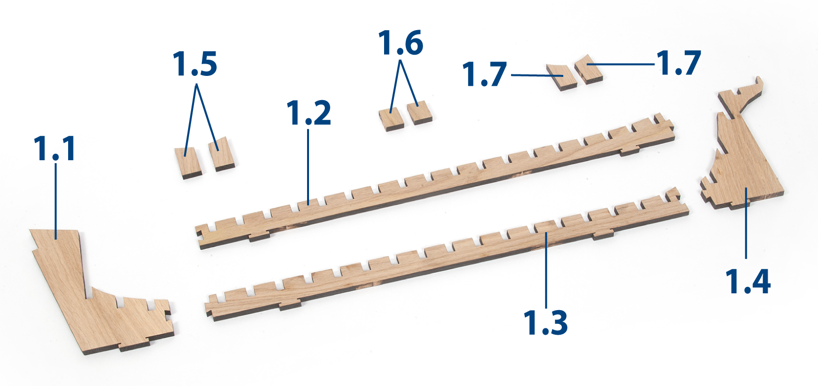
PACK 01 - PARTS IDENTIFICATION
PARTS REFERENCE
PART NO. | REFERENCE | PART NO. | REFERENCE | PART NO. | REFERENCE |
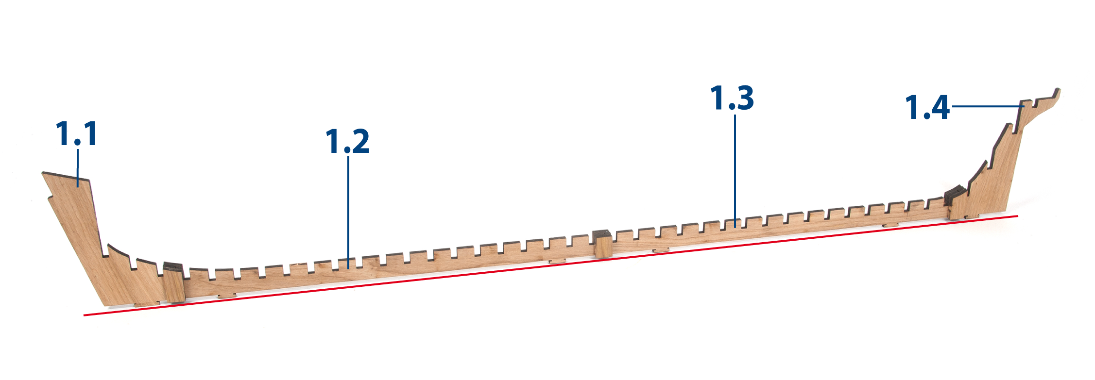
| 1.1 | 2002-2 | 1.9 | 2002-13 | 1.17 | 2002-3 |
| 1.2 | 2002-1 | 1.10 | 2002-14 | 1.18 | 2002-1 |
| 1.3 | 2002-1 | 1.11 | 2002-14 | 1.19 | 2002-3 |
| 1.4 | 2002-2 | 1.12 | 2002-14 | 1.20 | 2002-2 / 2002-3 |
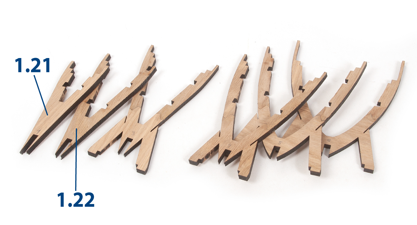
| 1.5 | 2002-1 | 1.13 | 2002-2 | 1.21 | 2002-2 |
| 1.6 | 2002-1 | 1.14 | 2002-1 | 1.22 | 2002-3 |
| 1.7 | 2002-2 | 1.15 | 2002-3 | 1.28 | 2002-15 |
| 1.8 | 2002-25 | 1.16 | 2002-3 |
Step 1
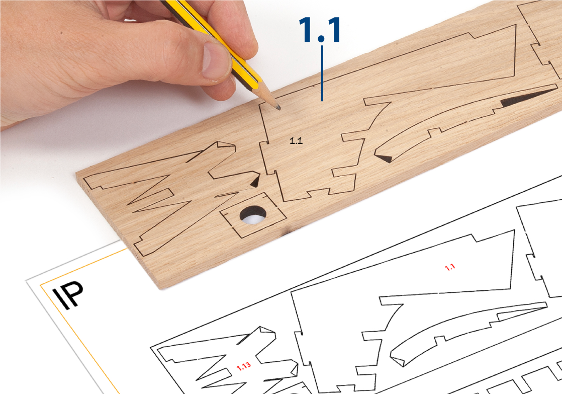
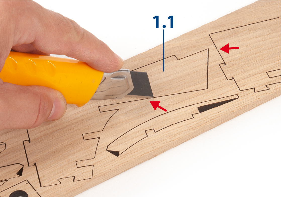
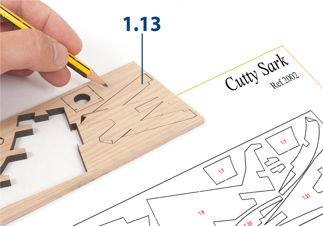
Prepare parts 1.1–1.7 as follows. Write the numbers using a pencil on the corresponding parts, referring to the diagrams above.
Step 2
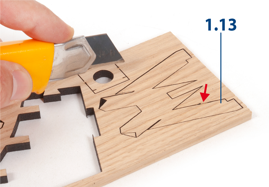
Cut out the parts with a craft knife.
Step 3
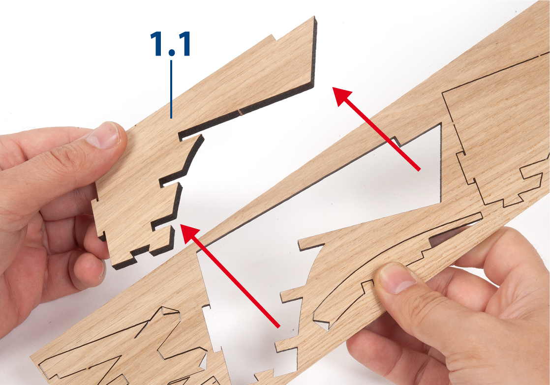
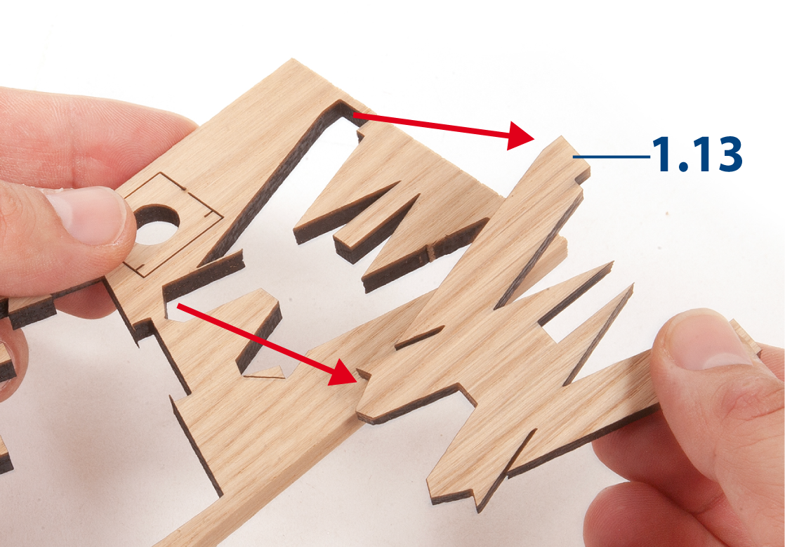
Only remove the parts you are working on in each step, and do so carefully to avoid breaking them.
Step 4
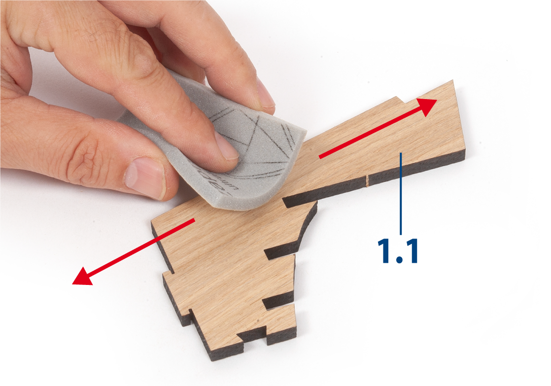
Sand the parts with fine-grit sandpaper or sanding sponge.
Step 5
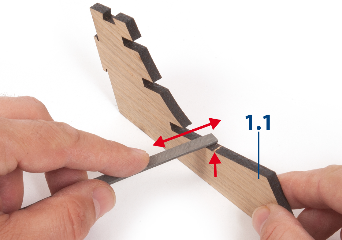
Use a small file to remove any remnants of the connecting ribs from the parts.
Step 6
Parts 1.1 to 1.7 form the false keel.
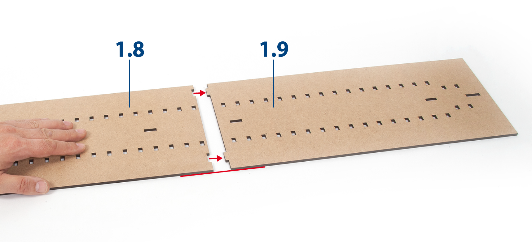
Step 7
Place parts 1.8 and 1.9 on a flat surface, align them as shown, then glue the parts together.
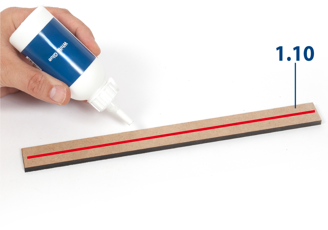
Step 8
Apply white glue to one side of part 1.10.
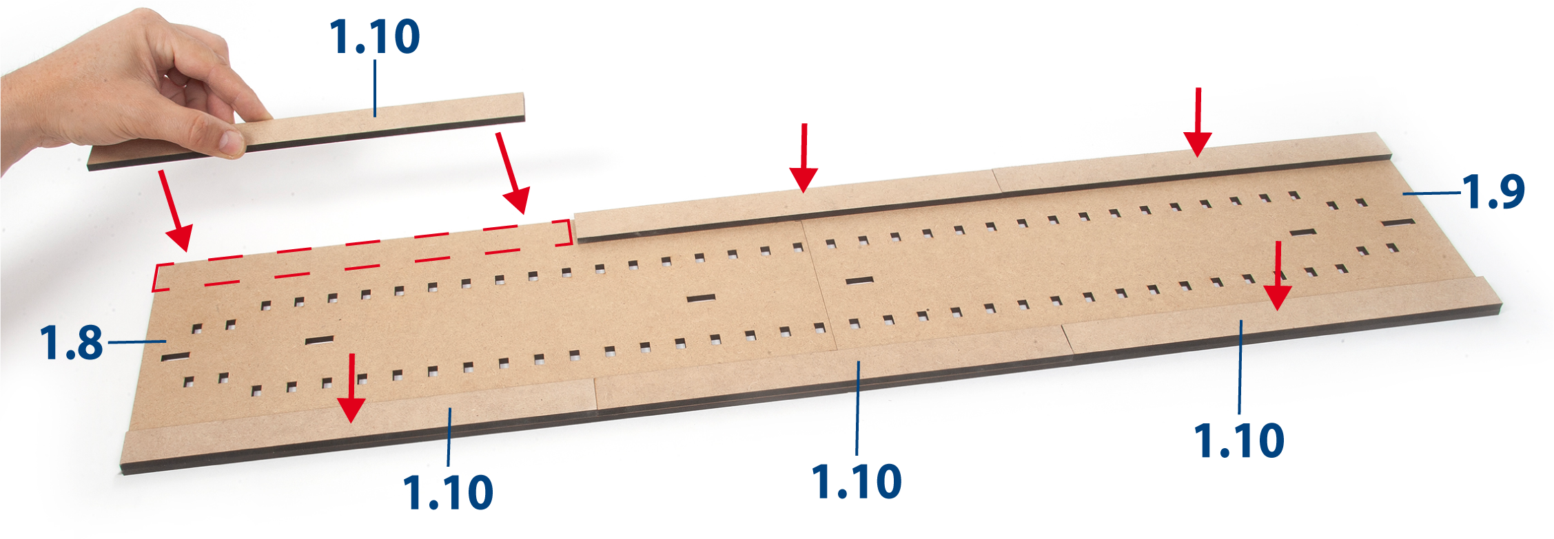
Step 9
Glue parts 1.10 along the outer edge of the building board. Keep the assembly flat until the glue dries.
Step 10
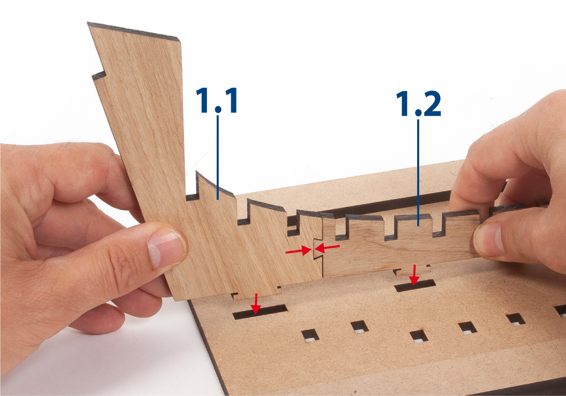
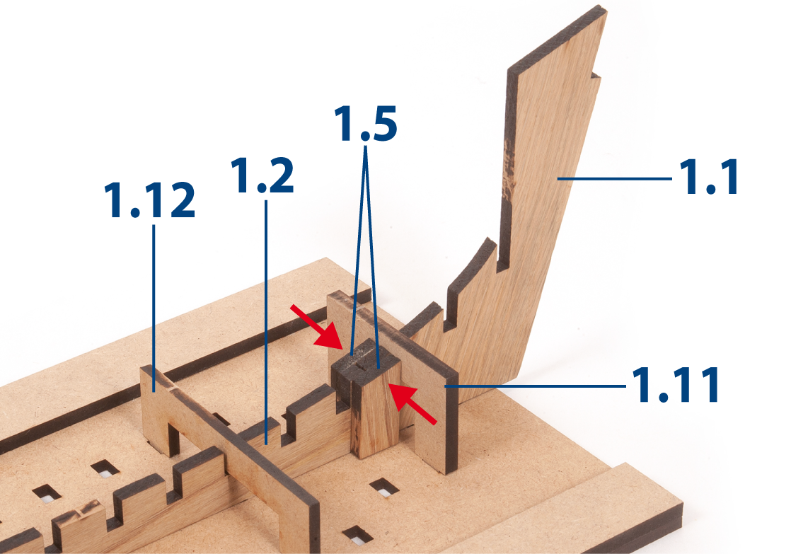
Important: Do not glue any of the parts in the following steps unless stated otherwise.
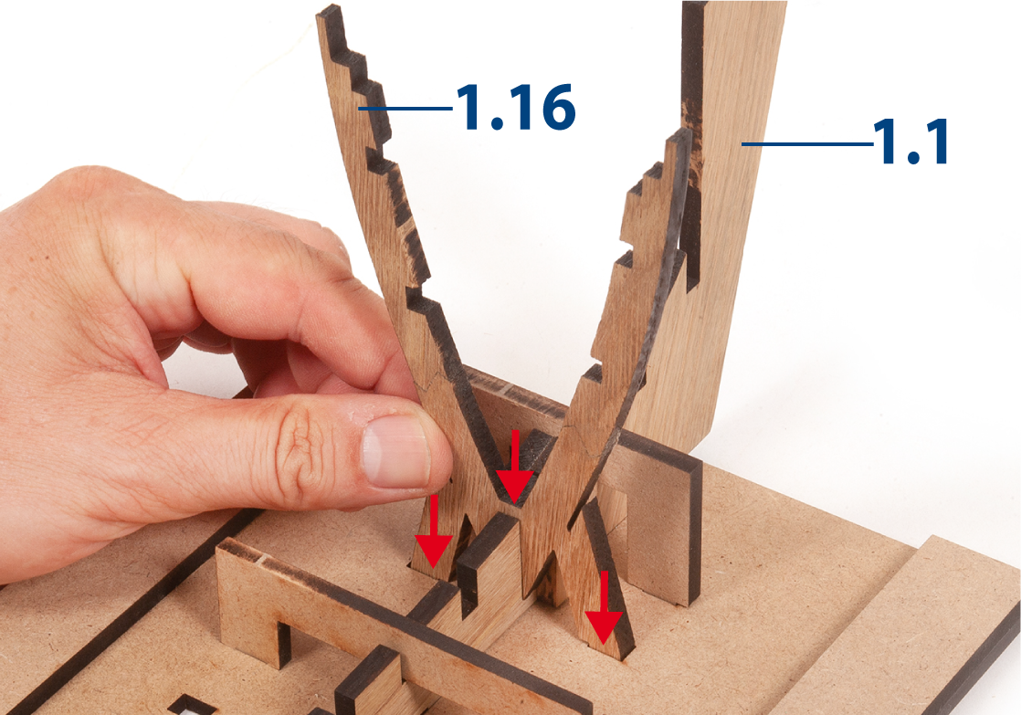
Fit parts 1.1 and 1.2 together, then insert them into the slots of the building board, as shown.
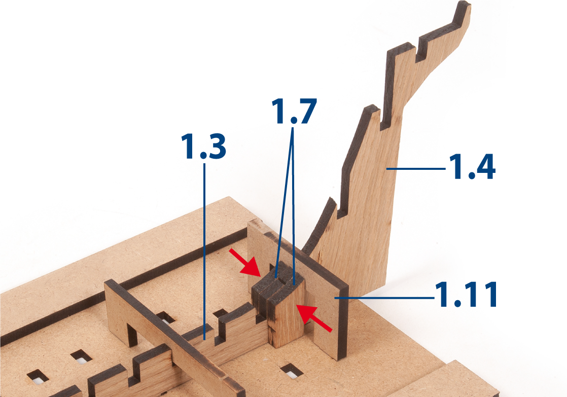
Step 11
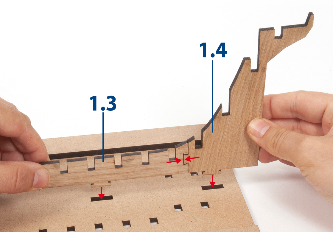
Fit parts 1.3 and 1.4 together, then insert them into the slots of the building board, as shown.
Step 12
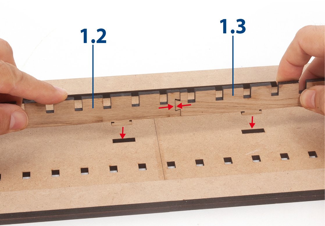
Join the two assemblies together in the slots, as shown.
Step 13
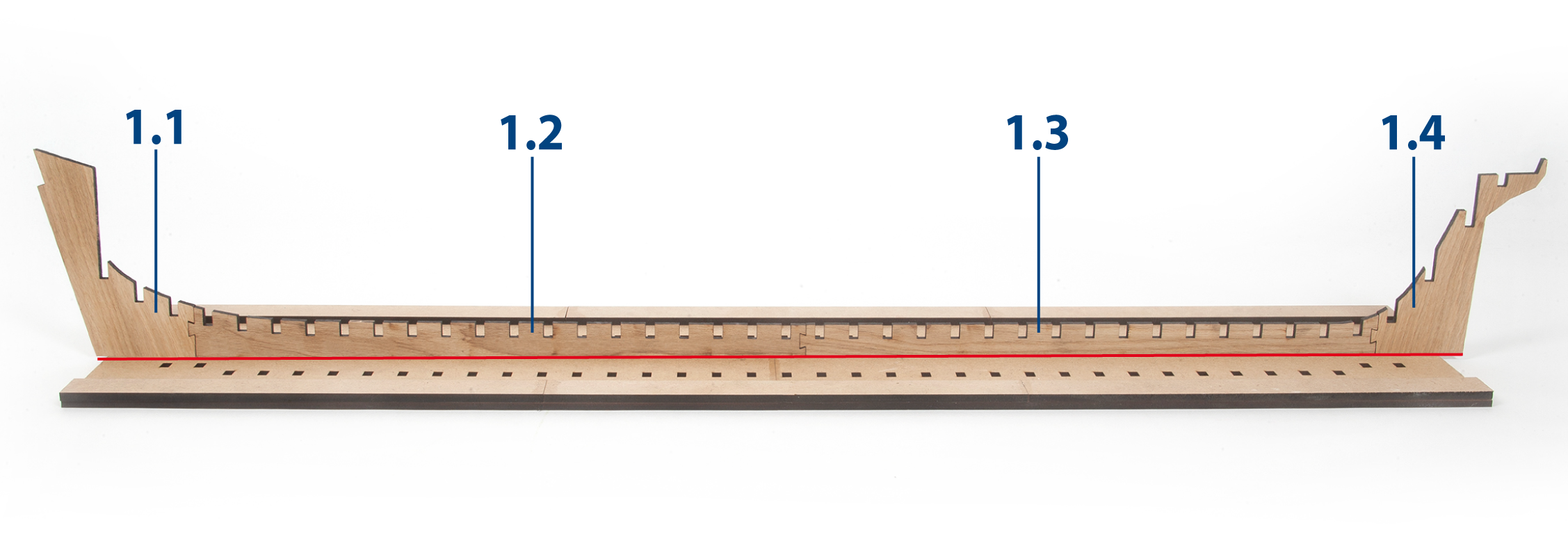
The building board will be used to keep the parts aligned during assembly. Do not glue the parts to each other or to the building board.
Step 1
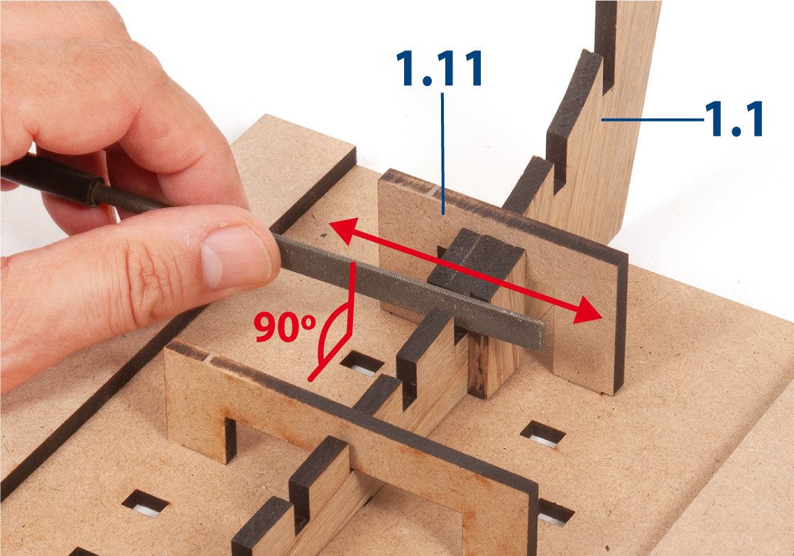
Insert parts 1.11 and 1.12 into the slots to hold the false keel in position, as shown. Do not glue.
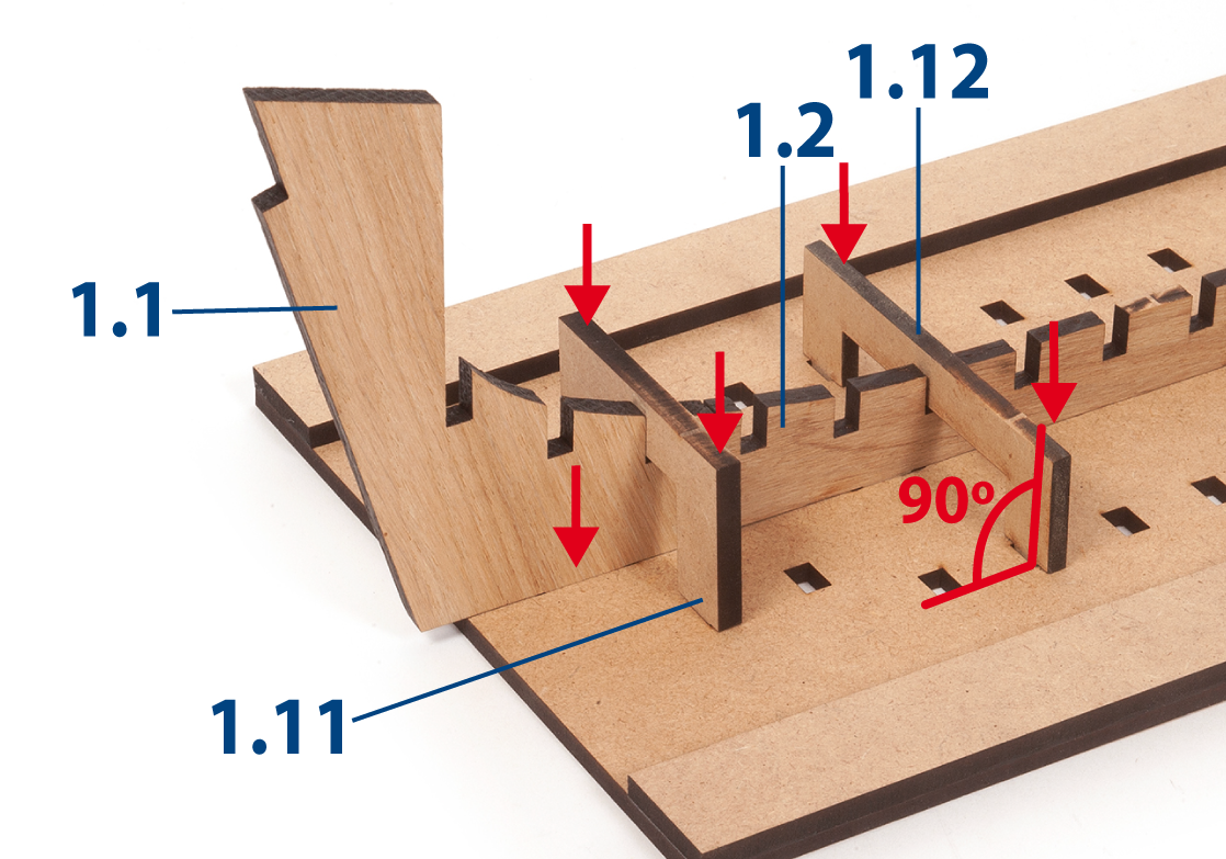
Step 2
Insert the remaining parts 1.11 and 1.12 into the slots.
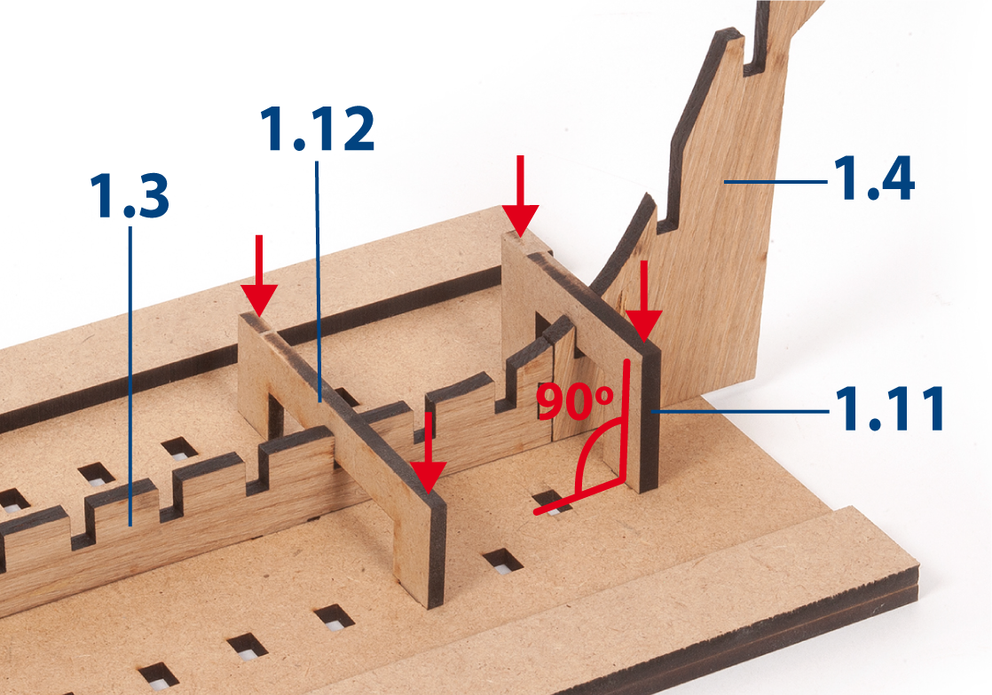
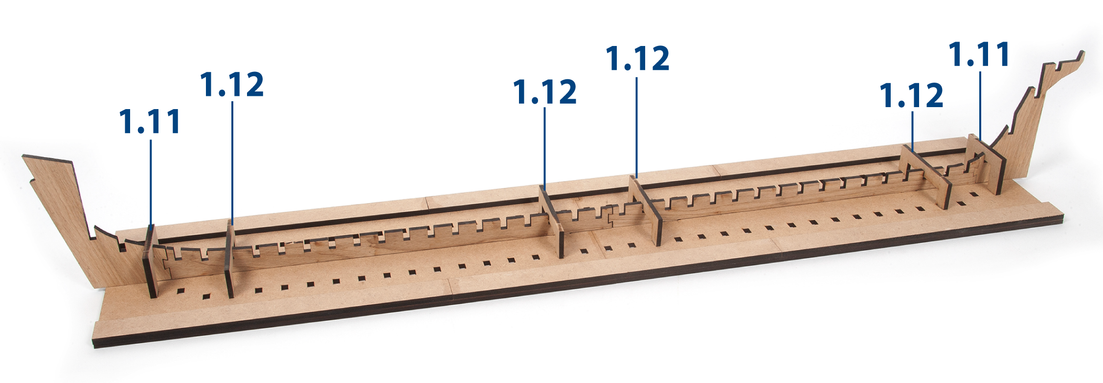
Step 3
The parts should now be positioned as shown.
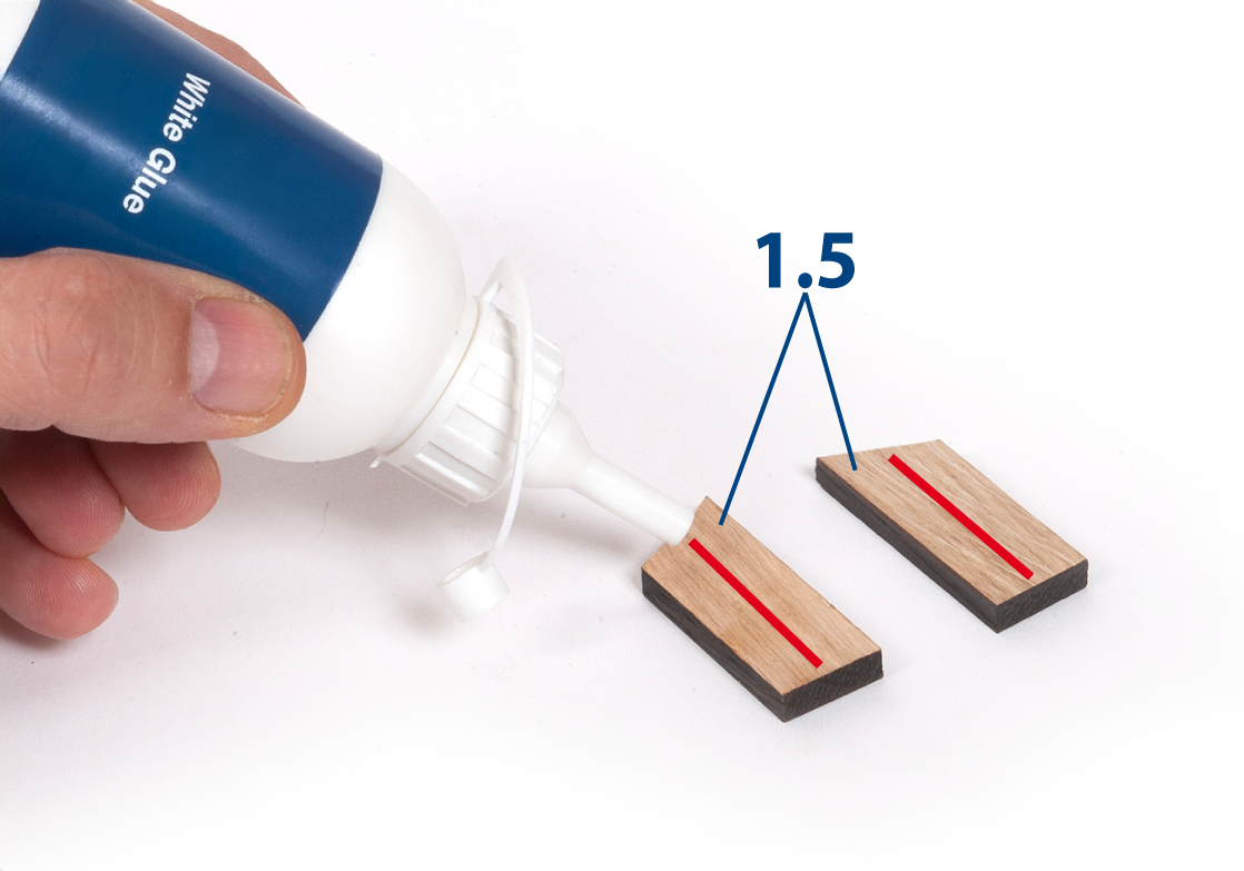
Step 4
Apply white glue to one side of parts 1.5, as shown.
Step 5
Glue one part 1.5 to each side of the joint between parts 1.1 and 1.2 ensuring that parts 1.5 are aligned. Take care not to get glue on part 1.11.
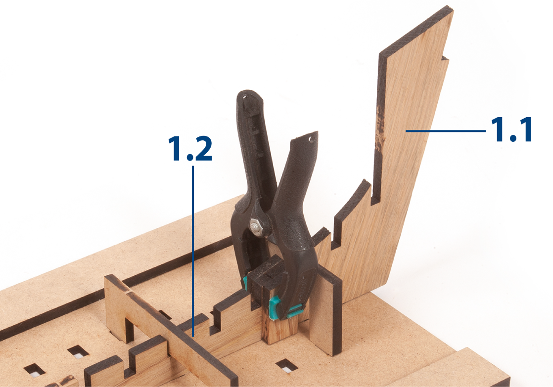
Step 6
Hold the parts firmly together with a clamp or a similar tool while the glue dries. Keep the assembly immobilised on the building board at all times.
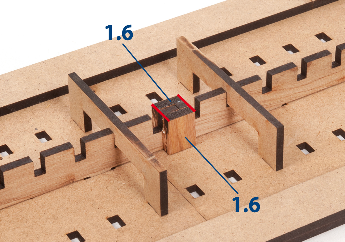
Step 7
Glue parts 1.6 to the assembly, as shown.
Step 8
Glue parts 1.7 to the assembly, as shown.
Step 9
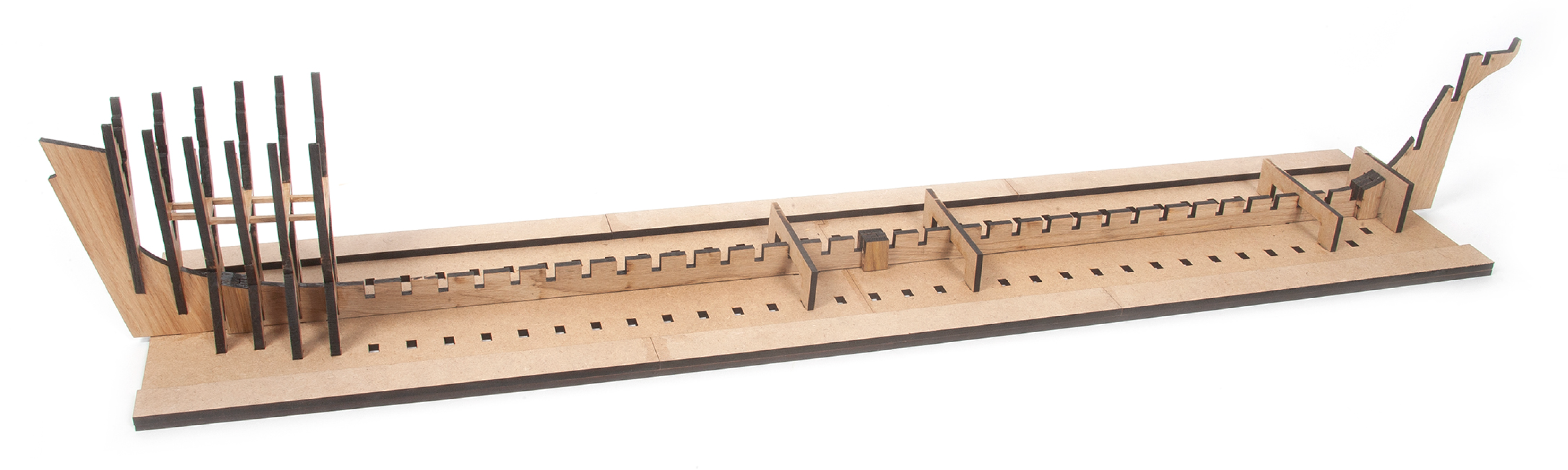
This image shows how the false keel looks without the building board, however, you must not remove it yet.
Step 1
Prepare parts 1.13–1.22 as follows. Write the numbers using a pencil on the corresponding parts, referring to the diagrams above.
Step 2
Cut out the parts with a craft knife.
Step 3
Only remove the parts you are working on in each step, and do so carefully to avoid breaking them.
Step 4
Sand the parts with fine-grit sandpaper or sanding sponge.
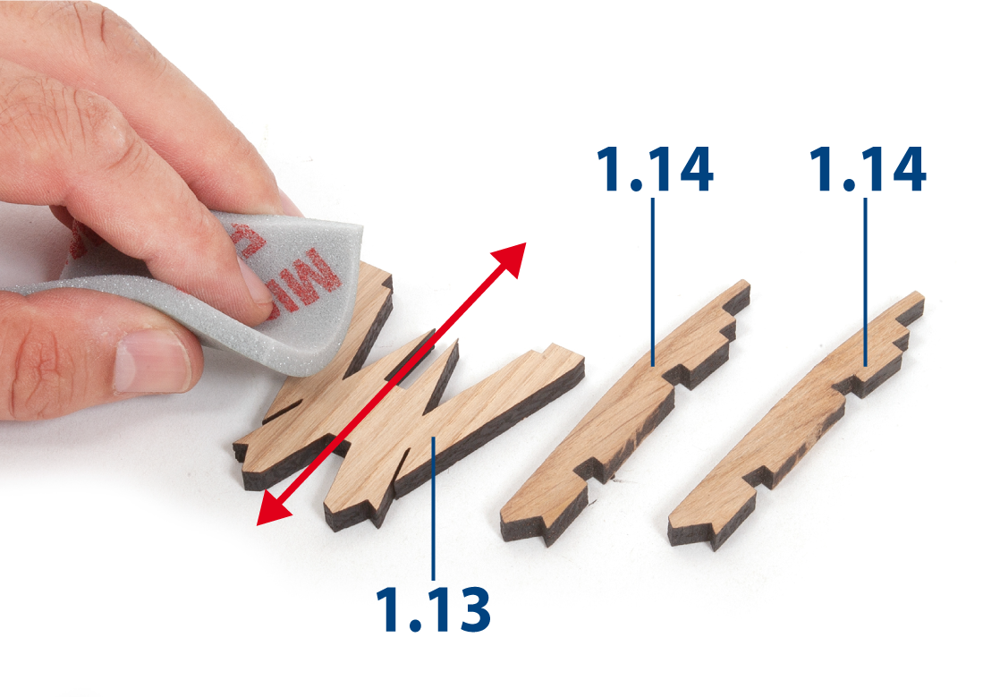
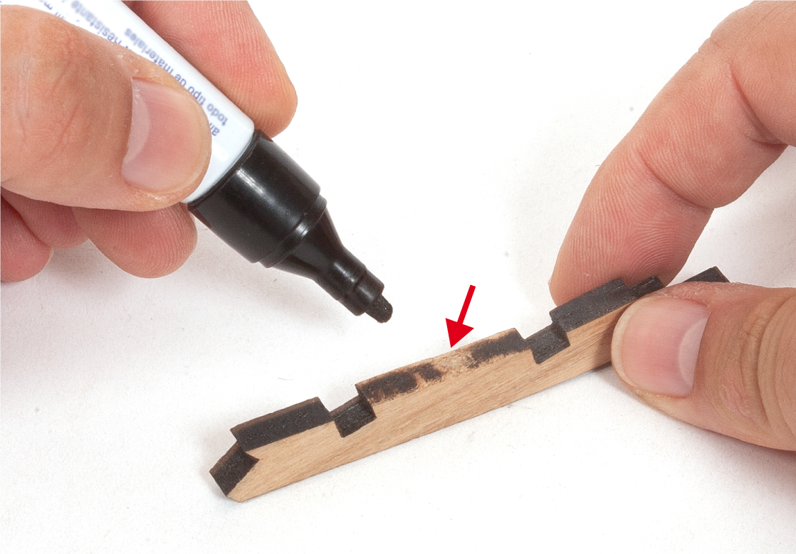
Step 5
You can colour in the pale wood areas using a black marker.
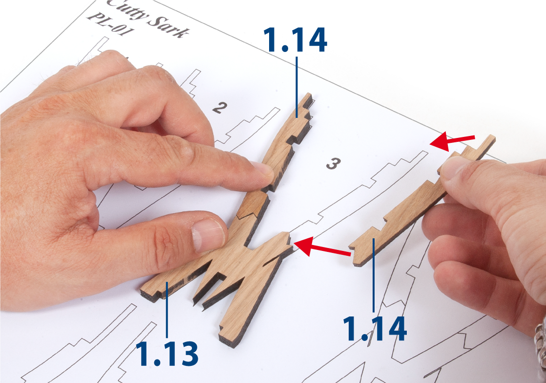
Step 6
Template PL-01 will serve as a guide for building the frames. Place parts 1.13 and 1.14 on the frame 3 outline to check the fit.
Expert Tip: you might find it helpful to lay a sheet of transparent plastic material over the template before gluing the frames. This will prevent the glue from sticking to the template.
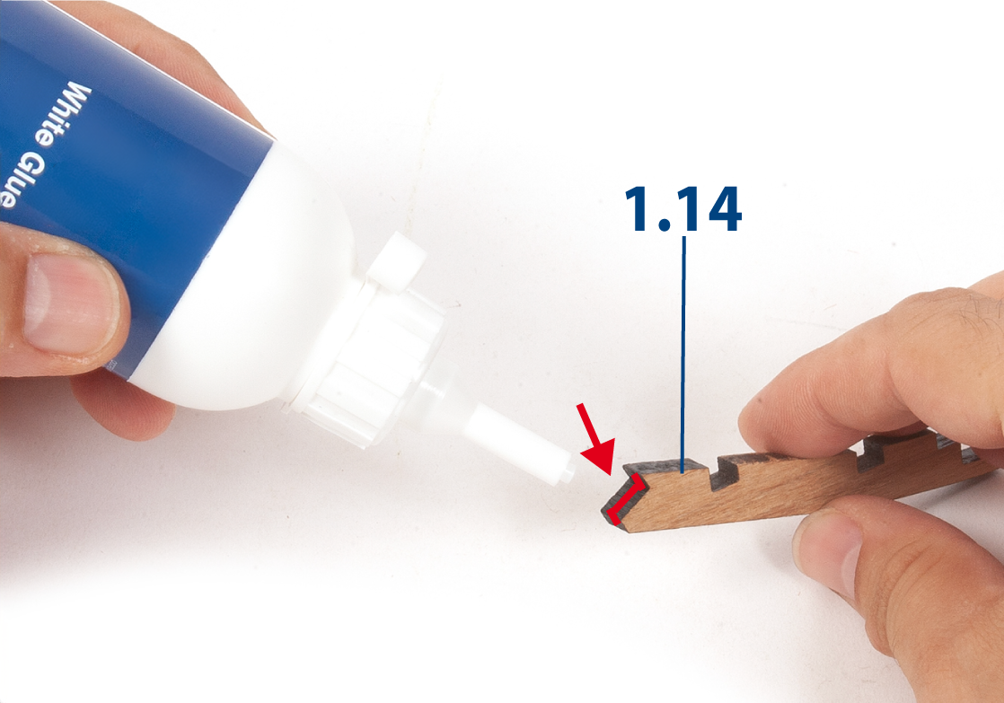
Step 7
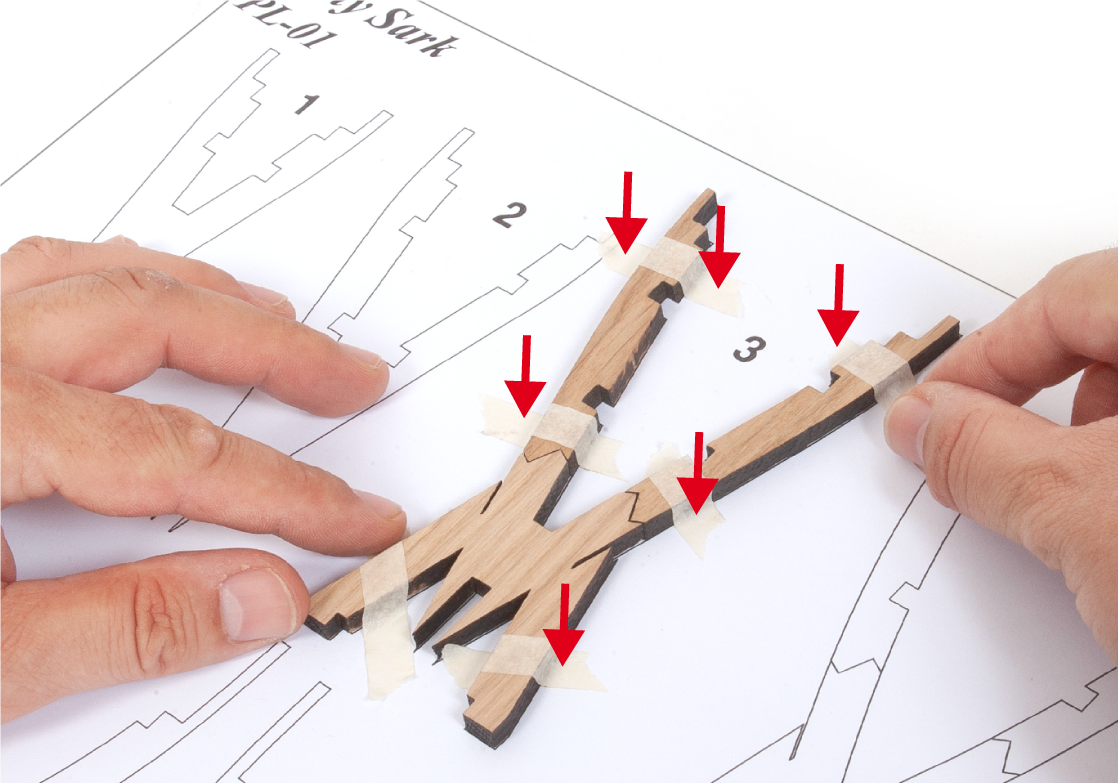
Apply glue to the ends of parts 1.14 and glue the pieces together to build frame 3.
Step 8
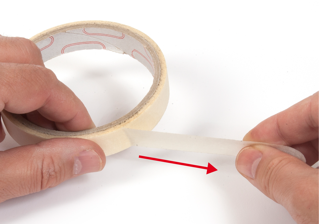
Use pieces of masking tape (painter's tape) to immobilise the parts on the template until the glue dries.
Step 9
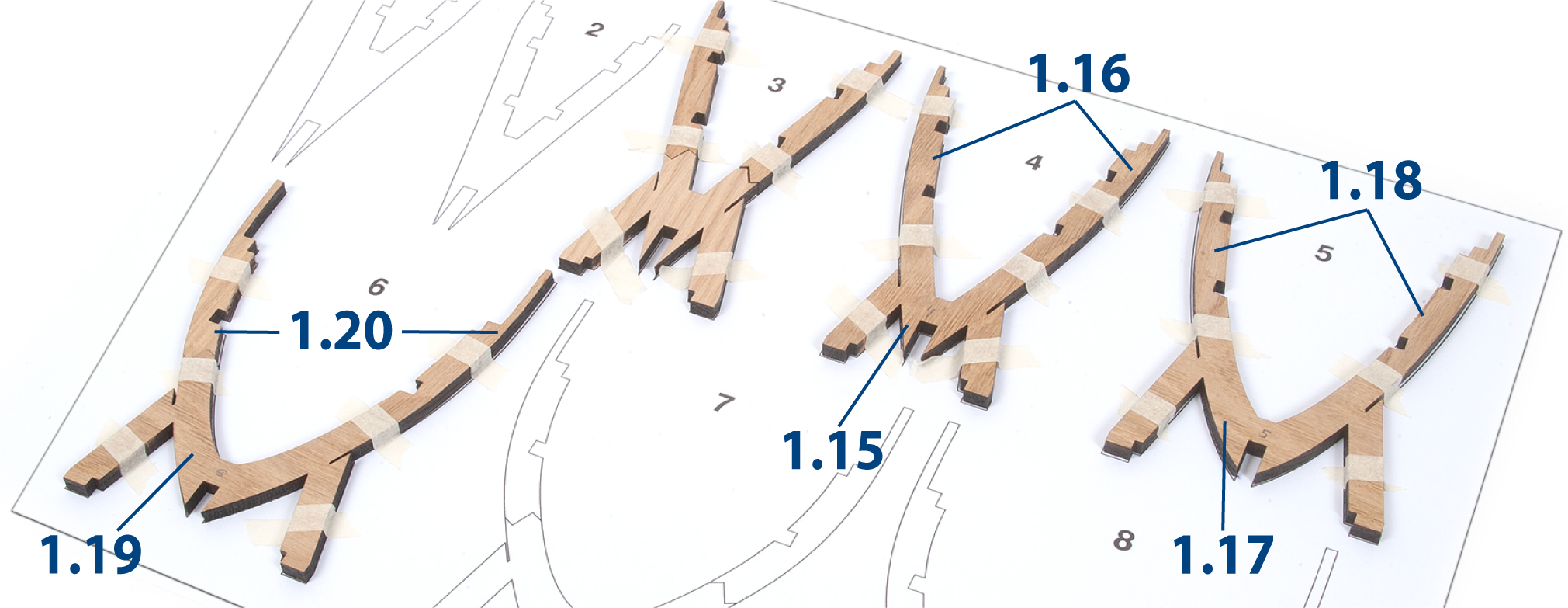
Follow the same procedure to build frames 4, 5 and 6.
Step 10
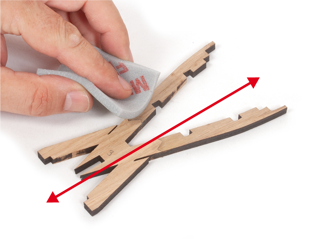
Sand the frames with a fine-grit sanding sponge to remove any glue or paper residue.
Step 11
You should now have six frames. Write the frame numbers (1–6) in pencil on each corresponding frame to identify them.
Step 12
Take the false keel and prepare it for inserting the frames by filing the slots if needed.
Step 13
Apply white glue to the fourth vertical slot of part 1.1, where frame 4 will make contact.
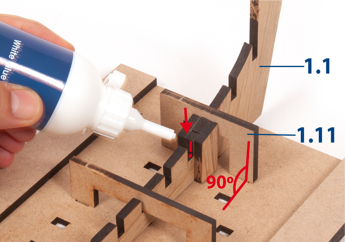
Step 14
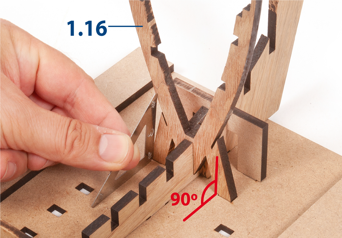
Insert frame 4 into the slots in the false keel and the building board. The frame should be glued to the false keel, but not to the building board.
Step 15
Check that frame 4 is square to the building board using a set square.
Step 16
Repeat the same procedure to glue and insert frames 5 and 6.
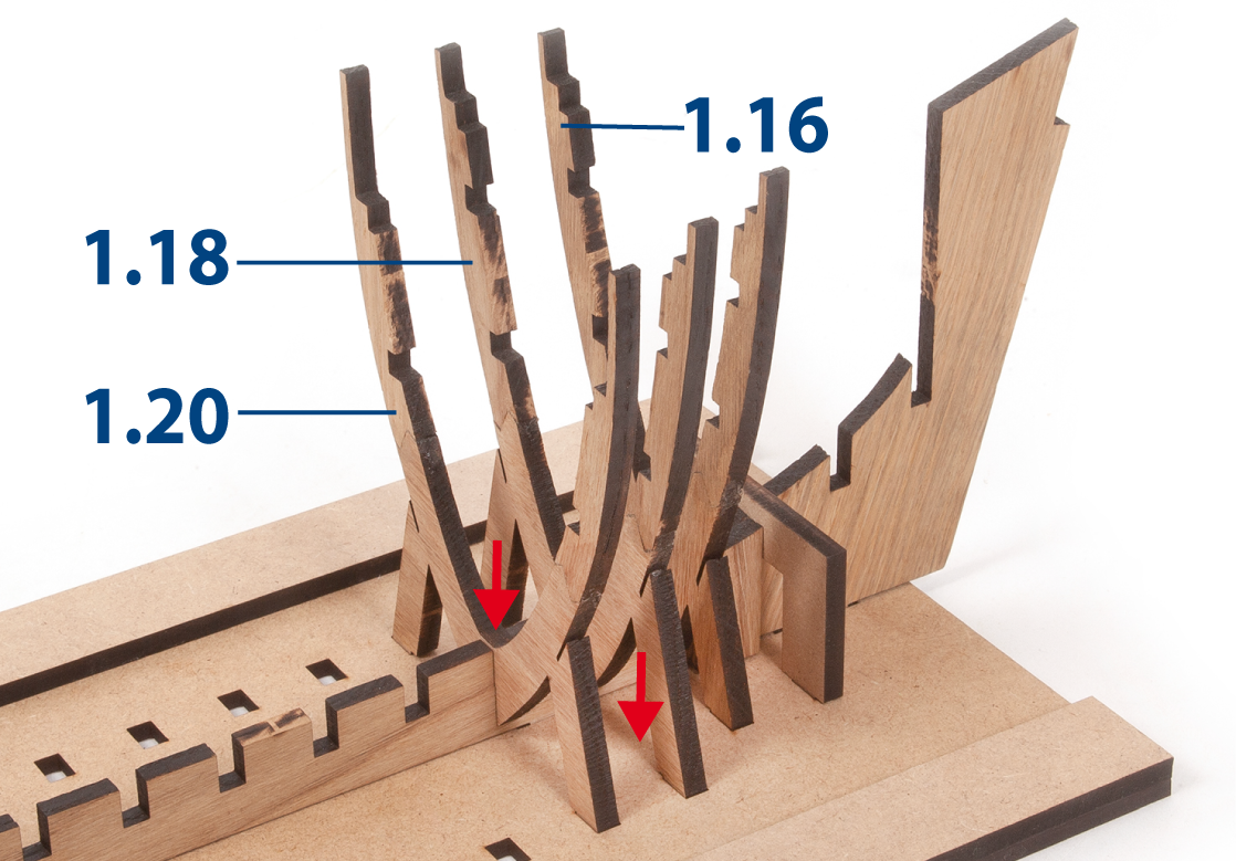
Step 17
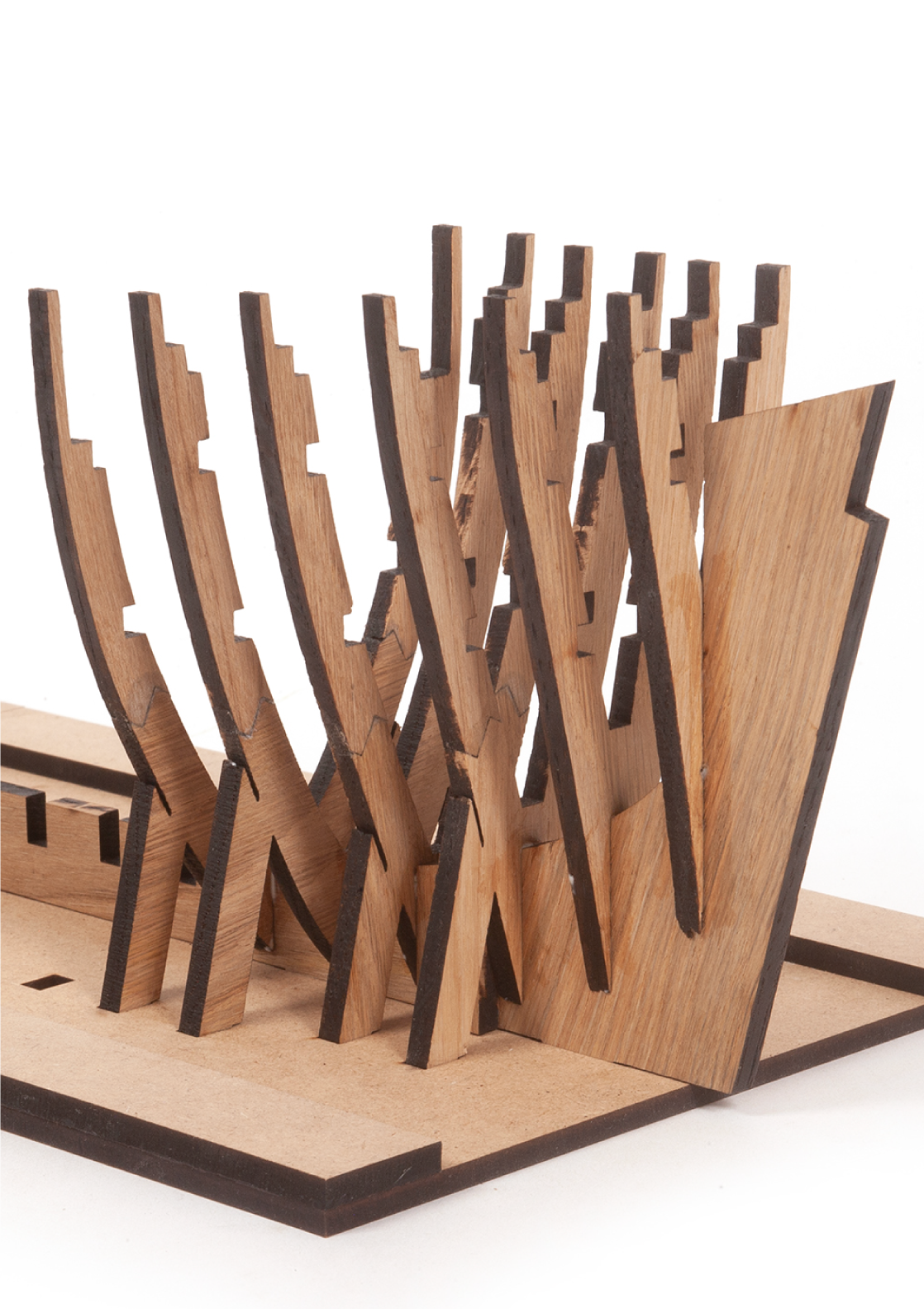
Insert and glue frames 1, 2 and 3. Keep the parts immobilised on the building board until the glue dries.
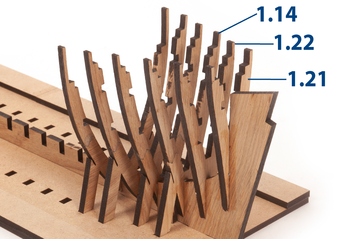
Step 18
The assembly should now look like this with the first six frames in place.
Step 1
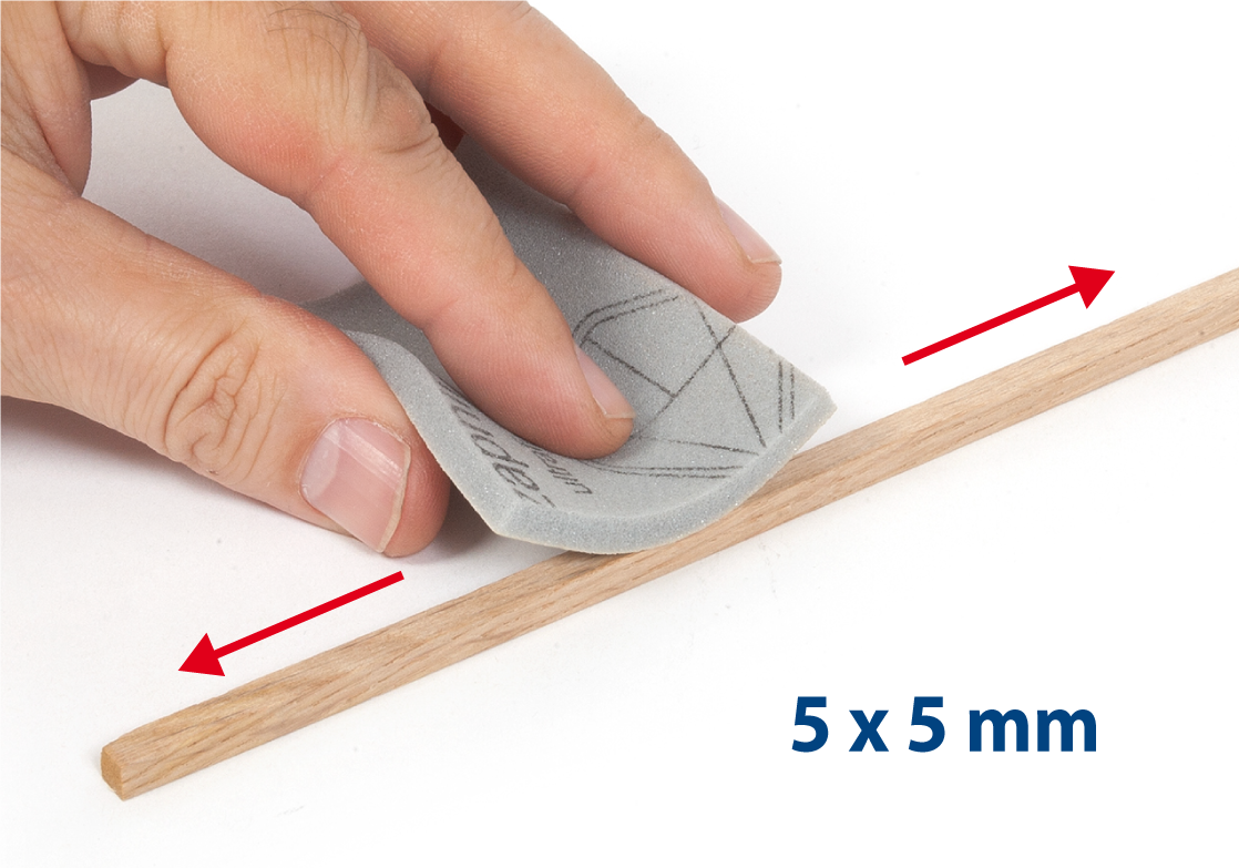
Sand a 5 x 5 mm oak strip with fine-grit sandpaper or sanding sponge.
Step 2
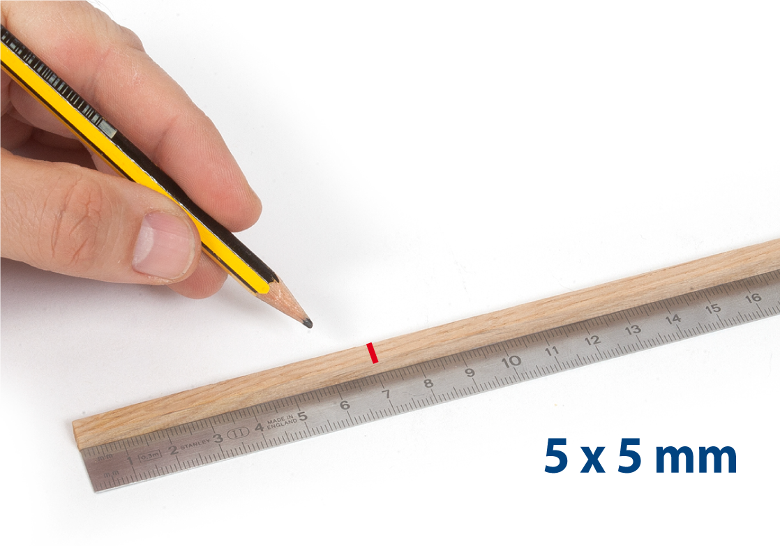
Measure a length of 71 mm for part 1.23 (5 x 5 x 71 mm).
Step 3
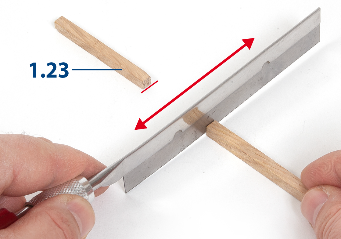
Cut part 1.23 using a saw.
Step 4
Sand both ends of the part using a sanding block or a flat file.
Step 5
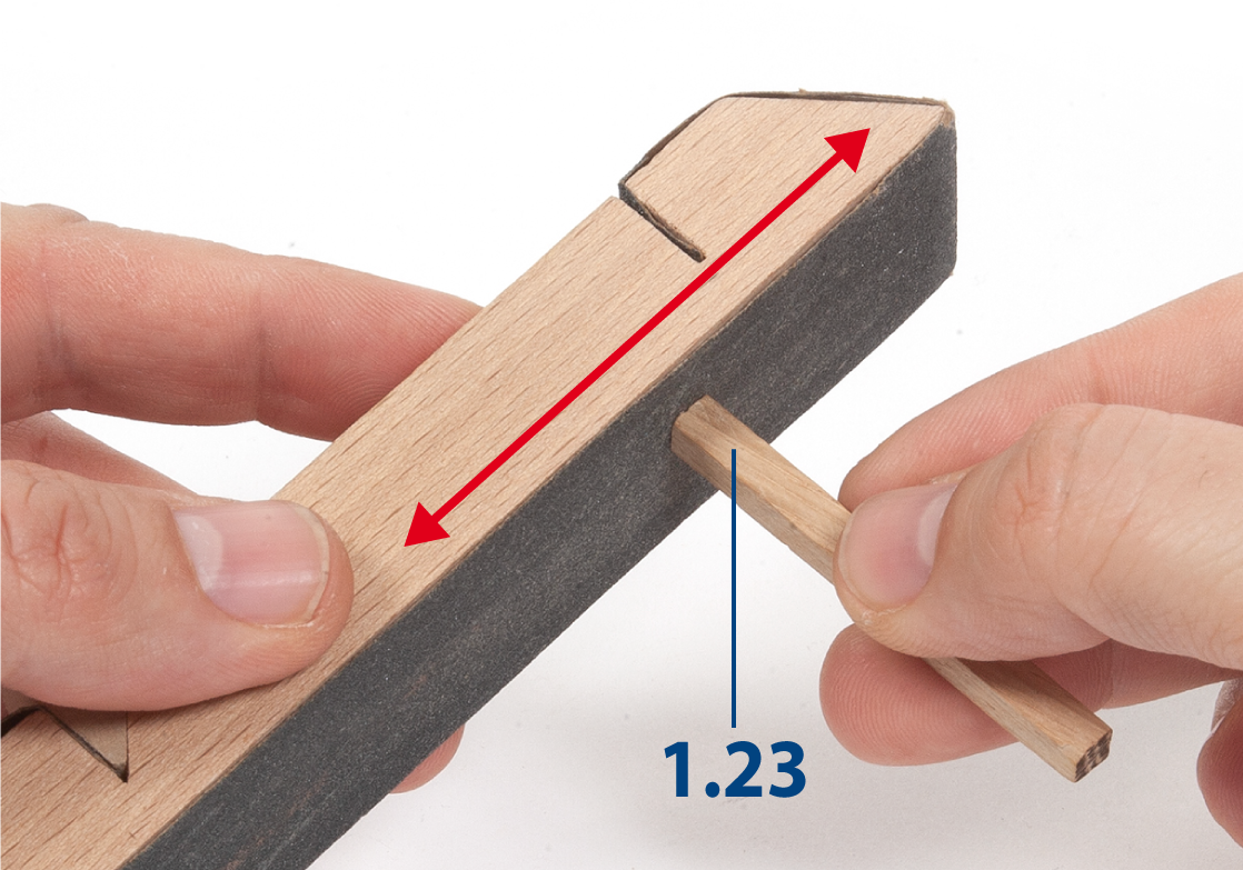
Apply glue to the ends of part 1.23.
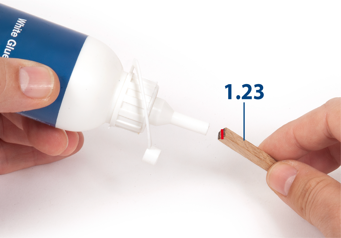
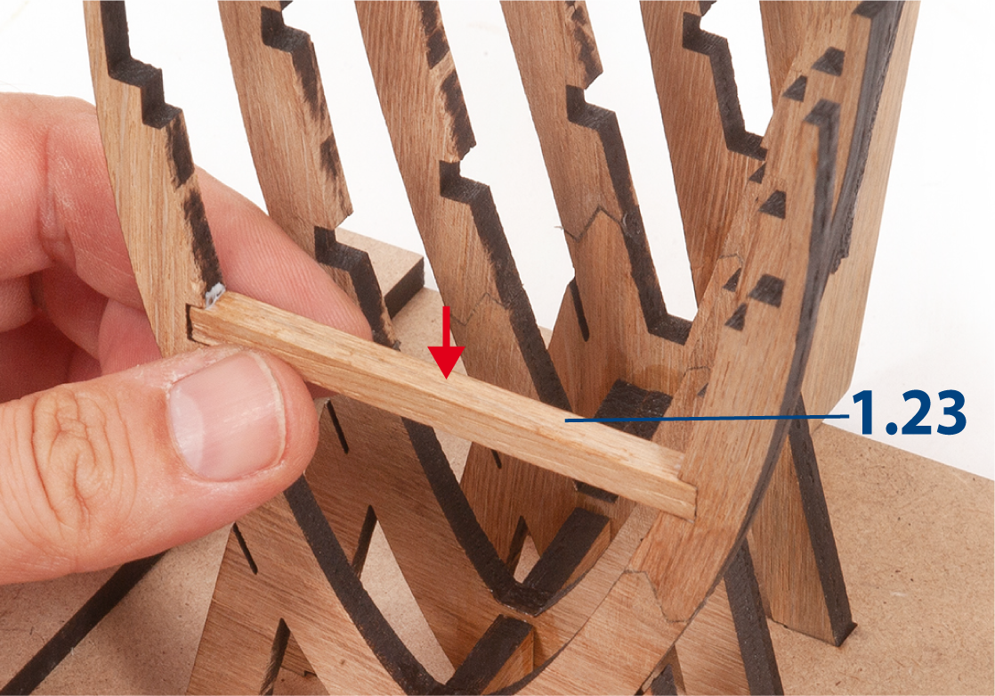
Step 6
Insert part 1.23 on the inside of frame 6, between its lower recesses.
Step 7
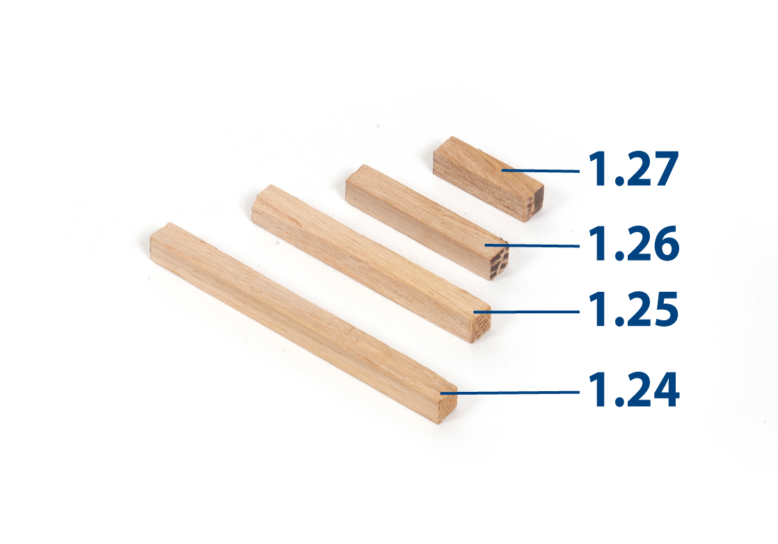
Cut parts 1.24–1.27 to the required length from a 5 x 5 mm oak strip.
| 1.24 | 5 x 5 x 58 mm |
| 1.25 | 5 x 5 x 46 mm |
| 1.26 | 5 x 5 x 31 mm |
| 1.27 | 5 x 5 x 20 mm |
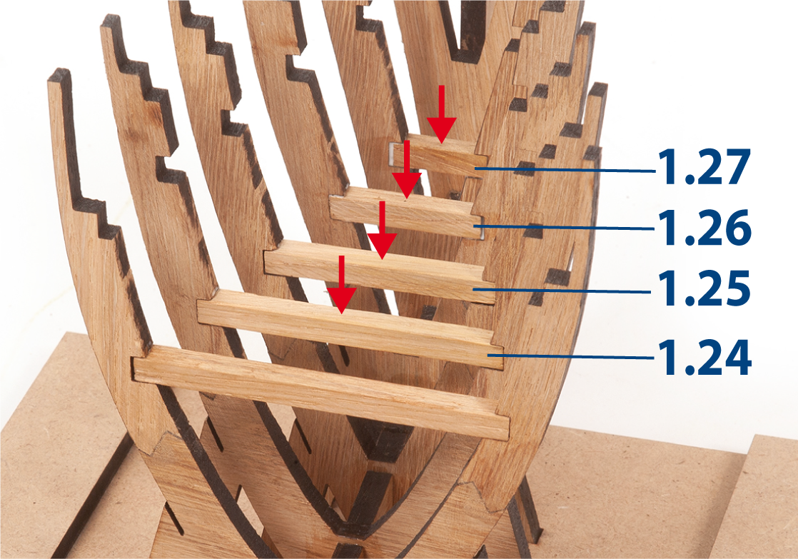
Step 8
Test-fit the oak strips between the frames, then glue each strip in place.
Step 9
Insert parts 1.28, without gluing, between the frames to keep them parallel.
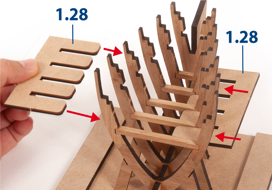
Step 10
Keep parts 1.28 in position for the next stage when working on the deck framework.
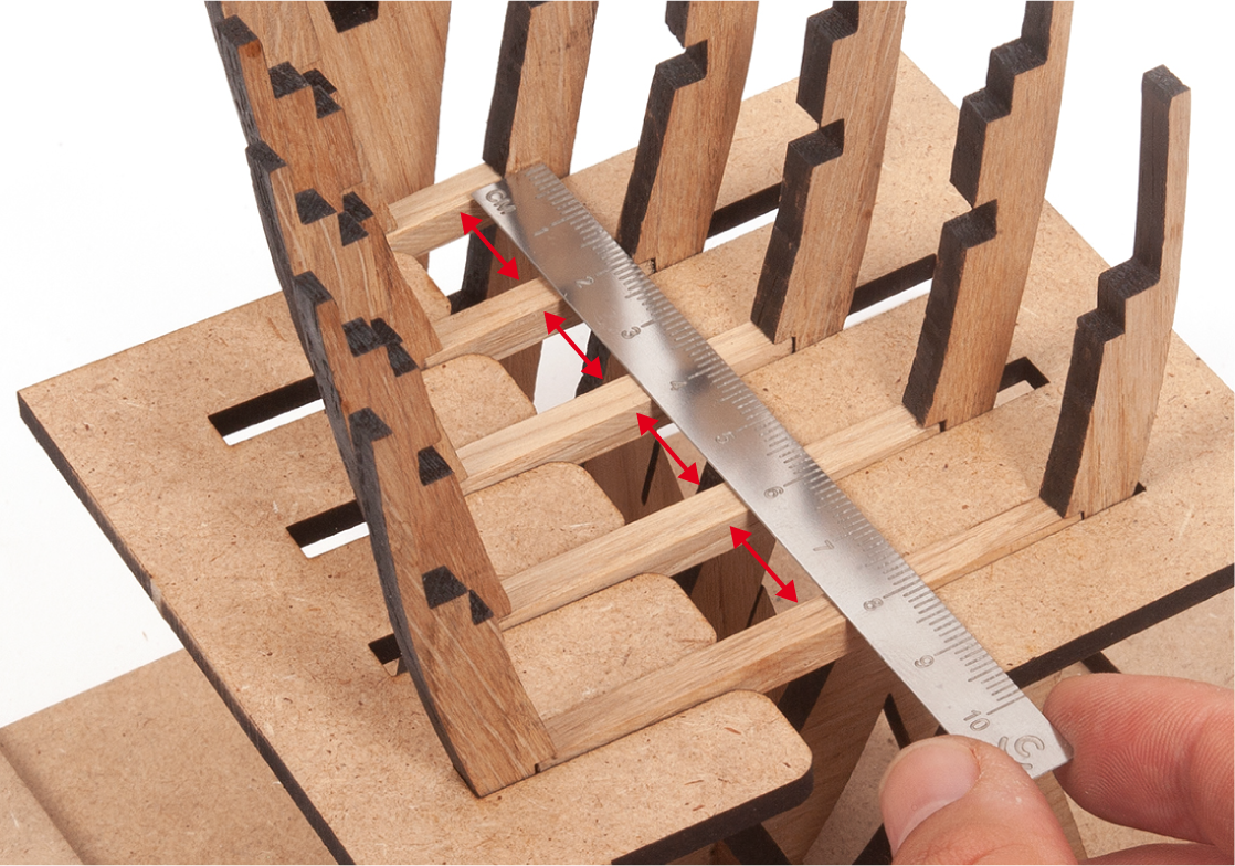
Step 1
Measure the distance between the deck beams on the frames.
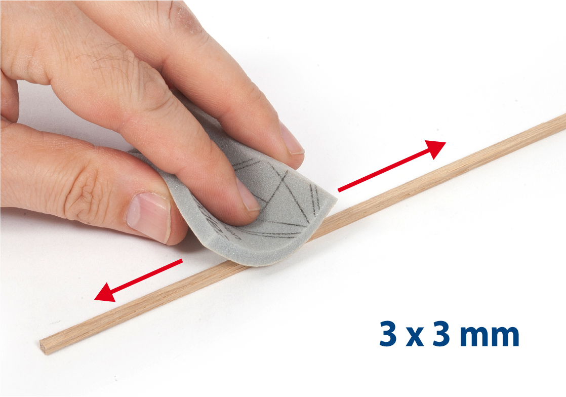
Step 2
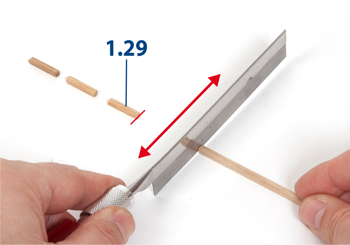
Sand a 3 x 3 mm oak strip with fine-grit sponge sandpaper.
Step 3
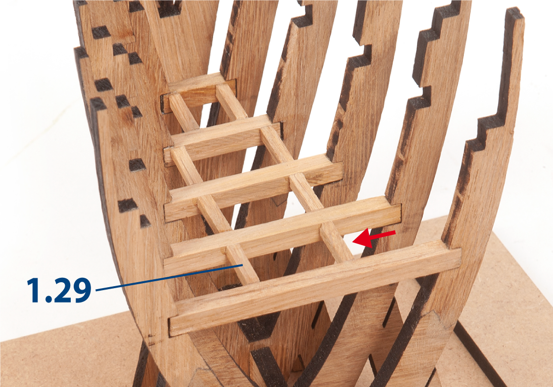
Cut eight parts 1.29 to the length measured in step 1 (approx. 3 x 3 x 15 mm).
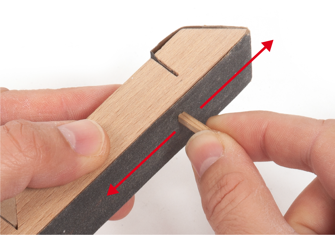
Step 4
Sand or file the ends of parts 1.29.
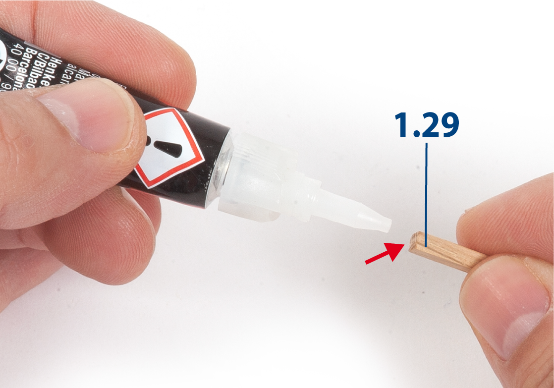
Step 5
Apply white glue, or super glue if preferred, to the ends of parts 1.29.
Step 6
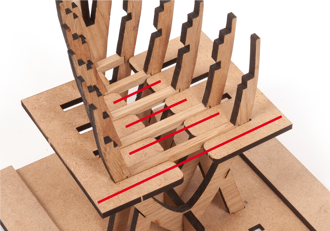
Glue two parts 1.29 level with the deck beams. Check the alignment with a ruler, then glue four more parts 1.29, as shown.
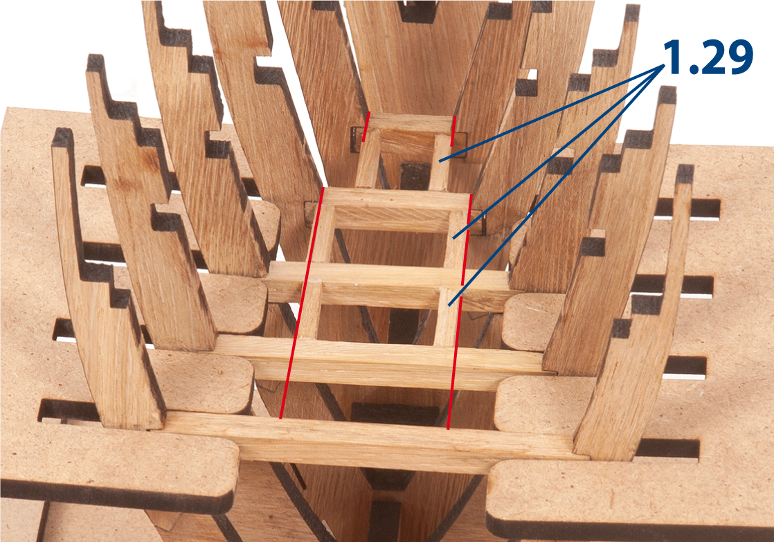
Step 7
Glue the remaining parts 1.29, aligned with the previous ones.
Remove parts 1.28 once the glue has dried.
Step 8
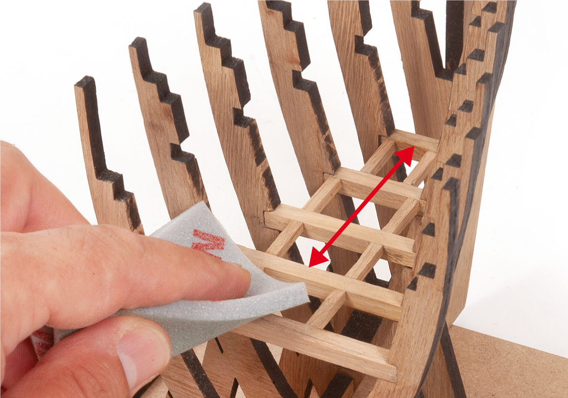
Sand the deck framework with fine-grit sandpaper or a sanding sponge.
Step 9
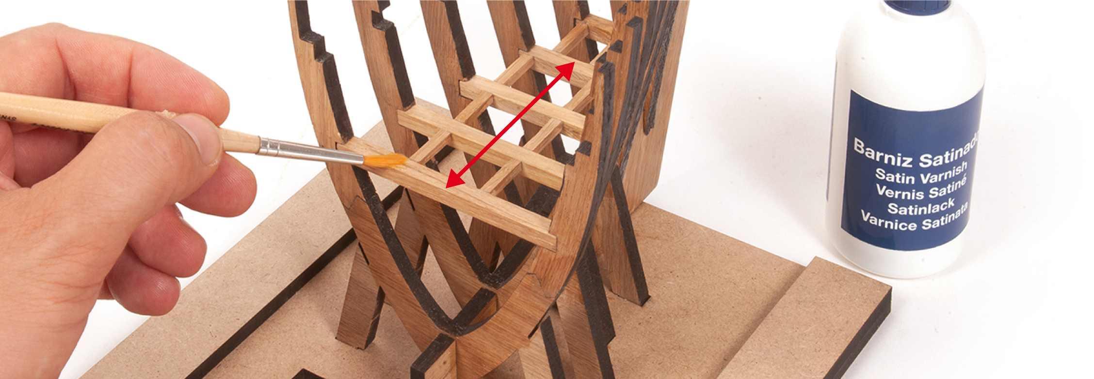
Apply clear varnish to the deck framing now, as it will be difficult to reach later. It is not necessary to varnish the slots in the frames, the frame legs or the building board.
Step 10
This image shows the assembly at the end of this stage. It is important to keep the structure on the building board at all times.