Pack 04
BUILD INSTRUCTIONS
Instructions for building your Cutty Sark model ship
Your model of the Cutty Sark is divided into 12 packs.
You will need to follow the step-by-step assembly photos, the plans and the explanatory texts below.
Please save the leftover materials from each pack for use when instructed to do so at a later stage of the assembly instructions.
The IP sheets displayed below are drawings of laser-cut parts and photo-etched brass parts and will serve as a guide for identification of some parts.
Use the PARTS REFERENCE table to help locate the parts.
The PL-00 templates (printed at 1/1 scale) will serve as a guide for building the frames.
Please check the list below to ensure you have all the tools required for building your wooden ship.
When removing a part, cut the ribs that join the part to the wooden plate with a cutter.
Remove the parts carefully so as not to break them.
Keep and store the parts in their frames. Only remove the parts you are working on in each step.
Extra support can be found on our forum.
PARTS LIST
| Material | Quantity | |
| Wooden Boards | ||
| 2002-12, 2002-17, 2002-19 | Wood | 3 |
| Wooden Strips | ||
| 5 x 5 x 400 mm | Oak | 9 |
| 3 x 3 x 400 mm | Lime wood | 6 |
| 2 x 3 x 600 mm | Lime wood | 15 |
| 2 x 3 x 600 mm | Mahogany | 4 |
| Wooden Rods | ||
| ø8 mm x 400 mm | Mahogany | 1 |
| Templates | ||
| Assembly templates PL-08 and PL-09 | 2 |
Tools you will need: cutting mat, pencil, cutting knife, fine-grit sandpaper or sponge sandpaper, file, white wood glue, super glue (cyanoacrylate glue), masking tape, set square, hacksaw, sanding block, 30 cm steel ruler, clamps, moulding scriber tool
PACK 04 PARTS IDENTIFICATION
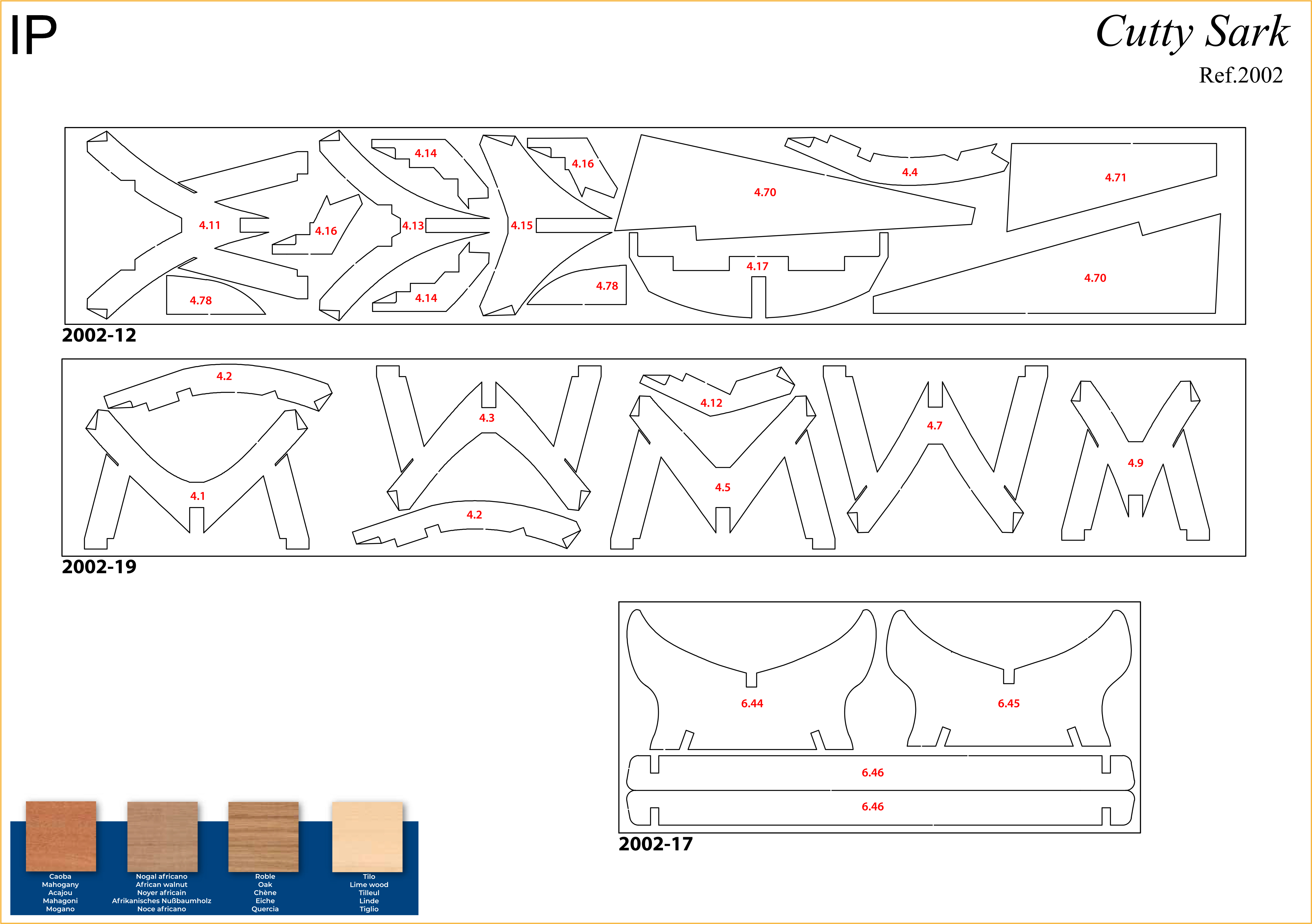
PARTS REFERENCE
PART NO. | REFERENCE | PART NO. | REFERENCE |
| 4.1 | 2002-19 | 4.17 | 2002-12 |
| 4.2 | 2002-19 | 4.18 | 2002-3 (pack 1) |
| 4.3 | 2002-19 | 4.33 | 2002-20 (pack 2) |
| 4.4 | 2002-10 (pack 3) / 2002-12 | 4.38 | 2002-20 (pack 2) |
| 4.5 | 2002-19 | 4.70 | 2002-12 |
| 4.6 | 2002-9 / 2002-10 | 4.71 | 2002-5 (pack 2) / 2002-12 |
| 4.7 | 2002-19 | 4.72 | 2002-3 (pack 1) / 2002-5 (pack 2) |
| 4.8 | 2002-8 / 2002-10 | 4.73 | 2002-8 (pack 3) / 2002-10 |
| 4.9 | 2002-19 | 4.74 | 2002-6 (pack 2) / 2002-8 (pack 3) |
| 4.10 | 2002-7 (pack 2) / 2002-9 (pack 3) | 4.75 | 2002-9 (pack 3) |
| 4.11 | 2002-12 | 4.76 | 2002-7 (pack 2) |
| 4.12 | 2002-7 (pack 2) / 2002-19 | 4.77 | 2002-8 (pack 3) |
| 4.13 | 2002-12 | 4.78 | 2002-12 |
| 4.14 | 2002-12 | 4.97 | 2002-2 (pack 1) |
| 4.15 | 2002-12 | 4.98 | 2002-20 (pack 2) |
| 4.16 | 2002-12 |
![]()
For extra support and guidance, John Builds Iconic Military Models demonstrates his build of the Cutty Sark on his YouTube channel, sharing 30+ years of wooden ship-building experience. Experts can be found on our Forum.
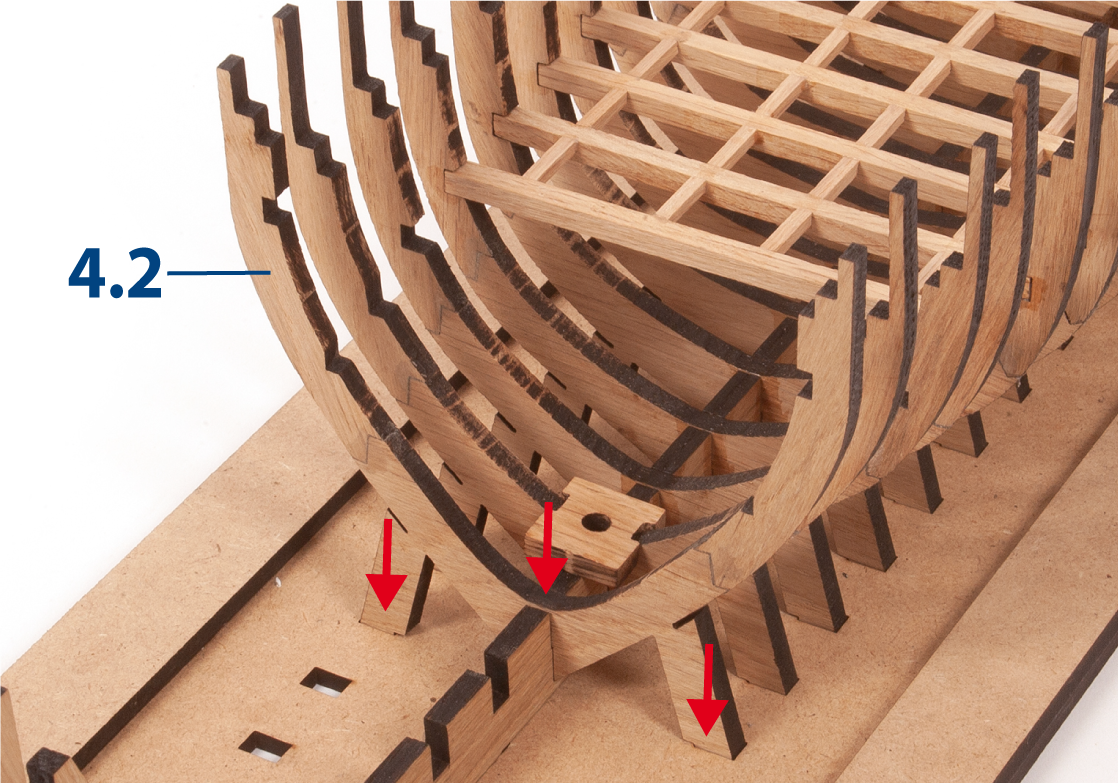
Step 1
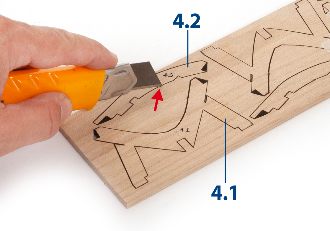
Prepare parts 4.1 and 4.2 as follows. Write the numbers using a pencil on the corresponding parts, referring to the diagrams above.
Cut out the parts with a craft knife.
Only remove the parts you are working on in each step.
Step 2
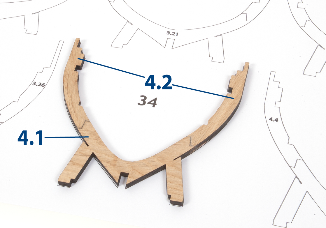
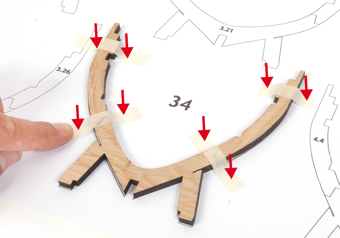
Place parts 4.1 and 4.2 on the frame 34 outline of template PL-07 to check the fit.
Step 3
Apply glue to the ends of the parts then glue the pieces together to build frame 34. Use pieces of masking tape to immobilise the parts on the template until the glue dries.
Step 4
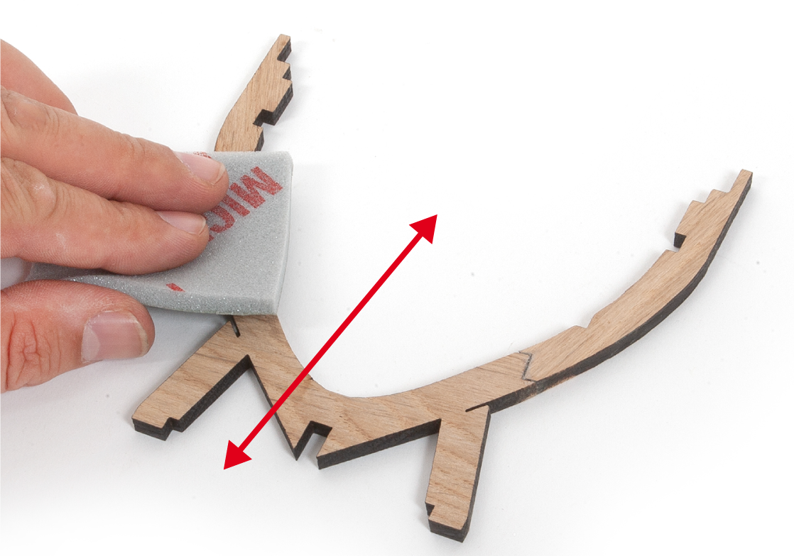
Once the glue has dried, sand the frame with a fine-grit sanding sponge to remove any glue or paper residue. Write number 34 in pencil on the frame.
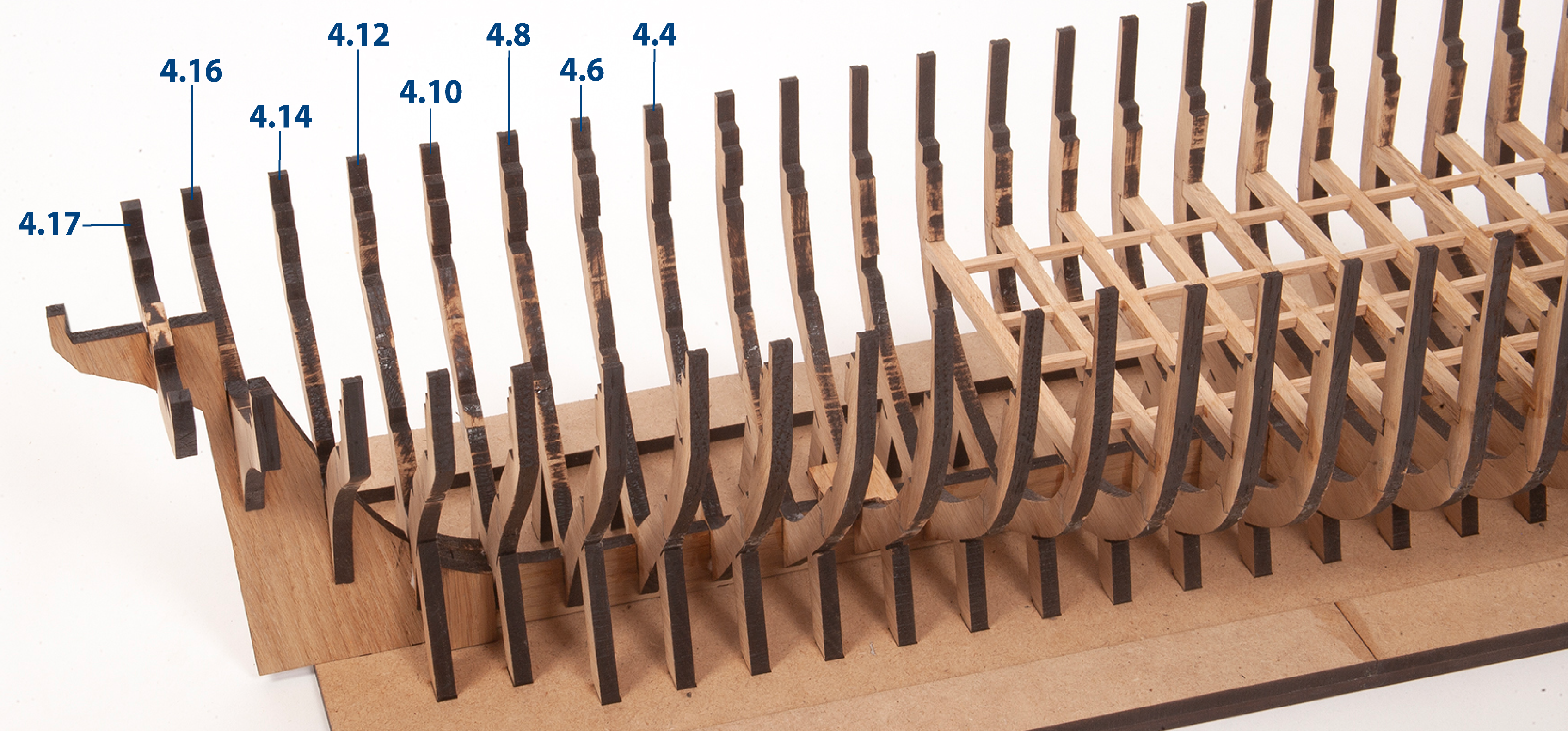
Step 5
Repeat this procedure to build frames 35–41, using templates PL-07 and PL-08 as guides. Write the frame numbers (35–41) in pencil on each frame.
Cut out part 4.17 and write the number 42 in pencil on the frame.

Step 6
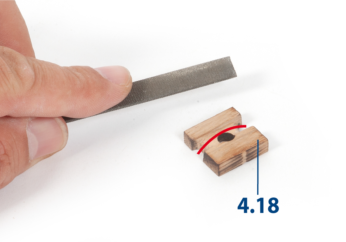
File part 4.18 (from pack 1, ref. 2002-3) so that it fits onto frame 33.
Step 7
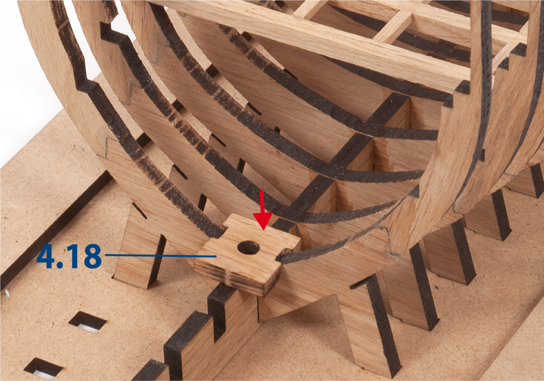
Glue part 4.18 to frame 33.
Step 8
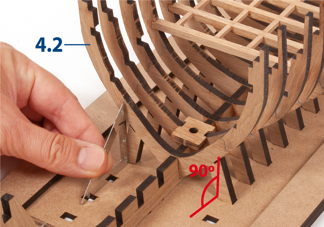
Test fit frame 34 into the slots of the false keel and the building board.
Step 9
Insert and glue frame 34. Check that the frame is square to the building board using a set square.
Step 10
Repeat the same procedure to glue frames 35–42.
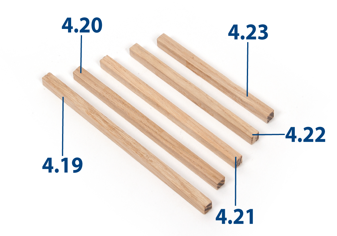
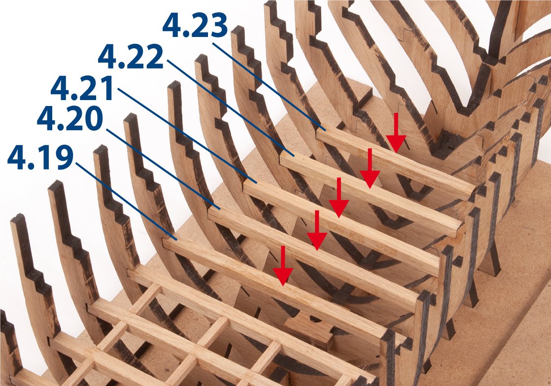
Step 1
Sand a 5 x 5 mm oak strip with fine-grit sandpaper or a sanding sponge. Then cut parts 4.19 to 4.23 to the lengths shown below.
| 4.19 | 5 x 5 x 105 mm |
| 4.20 | 5 x 5 x 93 mm |
| 4.21 | 5 x 5 x 86 mm |
| 4.22 | 5 x 5 x 78 mm |
| 4.23 | 5 x 5 x 69 mm |
Step 2
Insert and glue parts 4.19 to 4.23 between the lower recesses, as shown.
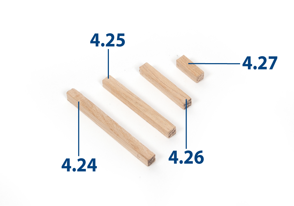
Step 3
Cut parts 4.24 to 4.27 from a 5 x 5 mm oak strip to the lengths shown below.
| 4.24 | 5 x 5 x 58 mm |
| 4.25 | 5 x 5 x 48 mm |
| 4.26 | 5 x 5 x 32 mm |
| 4.27 | 5 x 5 x 15 mm |
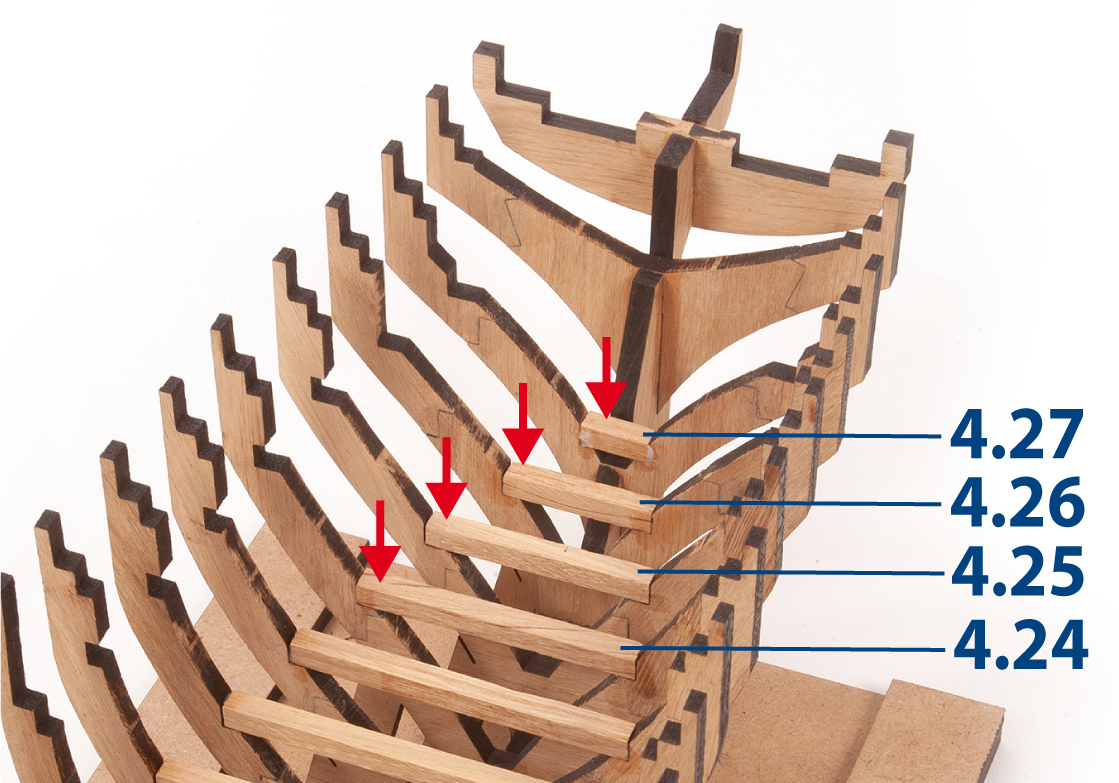
Step 4
Insert and glue parts 4.24 to 4.27 between the lower recesses, as shown.
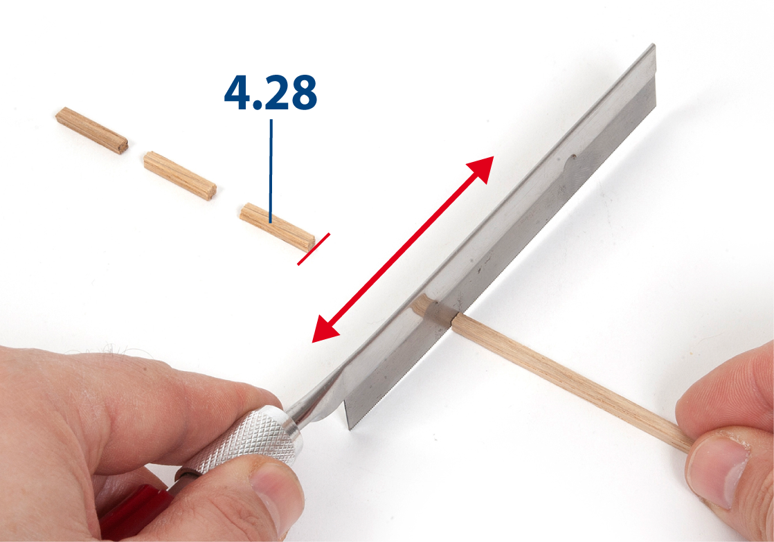
Step 5
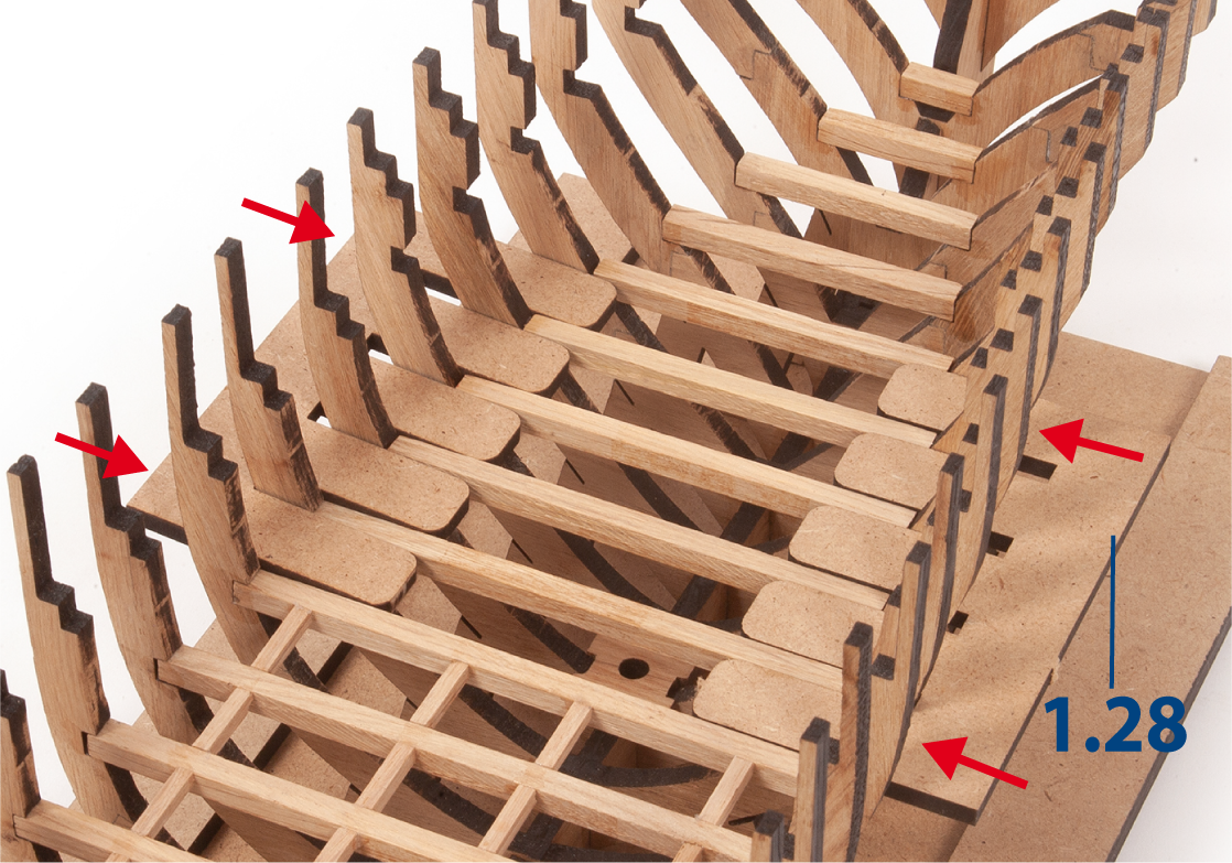
Sand a 3 x 3 mm lime wood strip with fine-grit sandpaper or a sanding sponge. Cut 26 parts 4.28 (3 x 3 x 15 mm) to length.
Step 6
Insert parts 1.28 between the frames to keep the frames parallel. Do not glue.
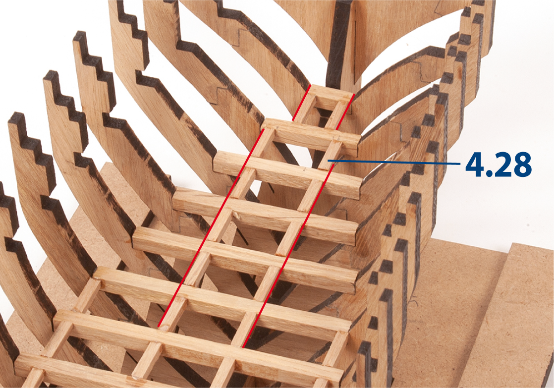
Step 7
Glue parts 4.28 in line with the previous parts. Use a ruler to align the strips, as indicated by the red lines.
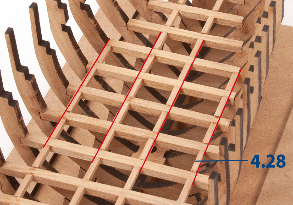
Step 8
Continue gluing pieces 4.28 in place, as shown.
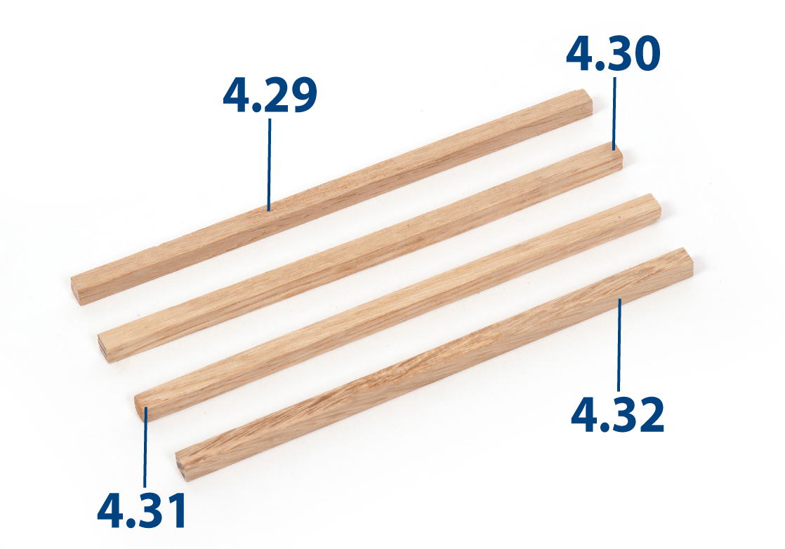
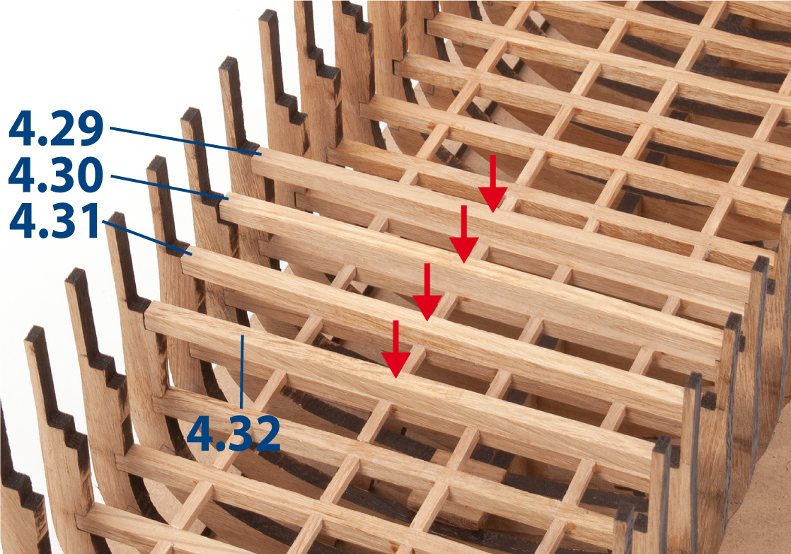
Step 9
Cut parts 4.29 to 4.32 from a 5 x 5 mm oak strip to the lengths shown below.
| 4.29 | 5 x 5 x 129 mm |
| 4.30 | 5 x 5 x 128 mm |
| 4.31 | 5 x 5 x 127 mm |
| 4.32 | 5 x 5 x 126 mm |
Step 10
Fit the parts between the upper recesses of frames 21–24. Do not glue.
Step 11
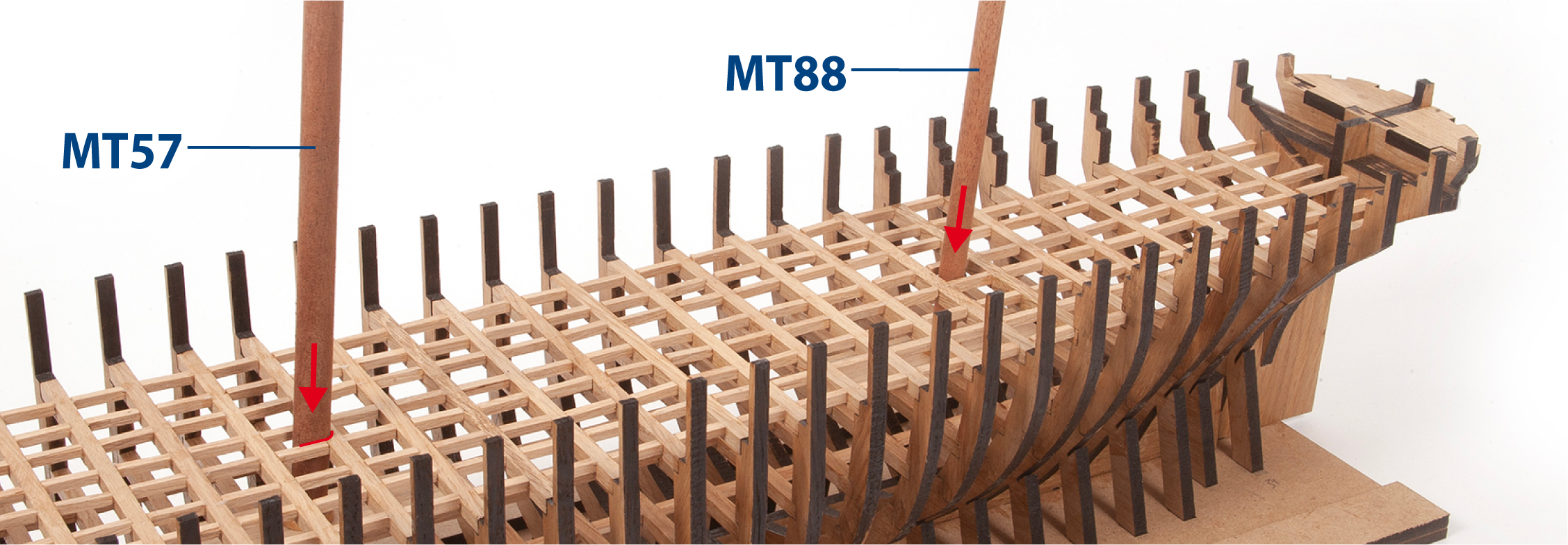
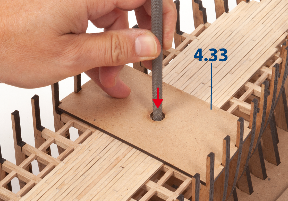
Carefully position part 4.33 between the frames and on the battens. Do not glue. Insert part MT57 into part 4.33 and into part 3.27 to check its fit.
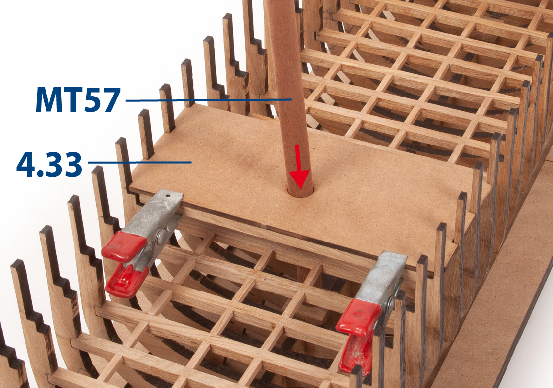
Step 12
This image shows the alignment of the parts.
Once part MT57 fits correctly in place, remove part MT57, part 4.33 and the battens, then set them aside.

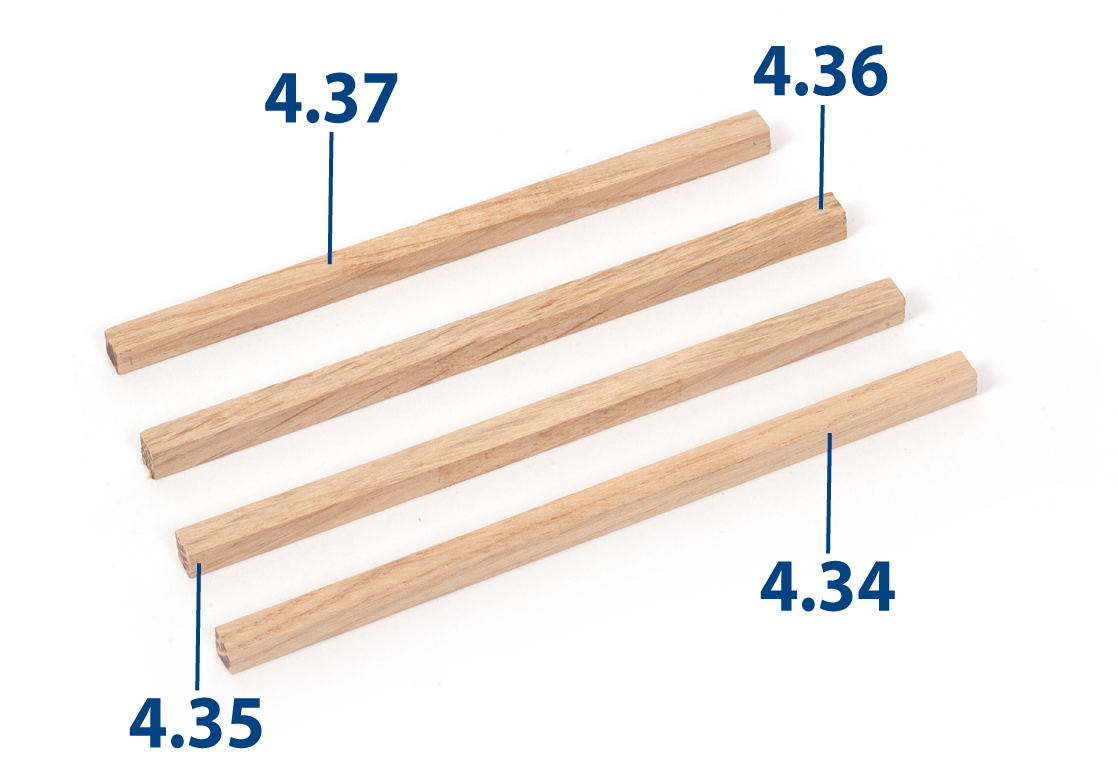
Step 13
Cut parts 4.34 to 4.37 from a 5 x 5 mm oak strip to the lengths below.
| 4.34 | 5 x 5 x 113 mm |
| 4.35 | 5 x 5 x 110 mm |
| 4.36 | 5 x 5 x 108 mm |
| 4.37 | 5 x 5 x 104 mm |
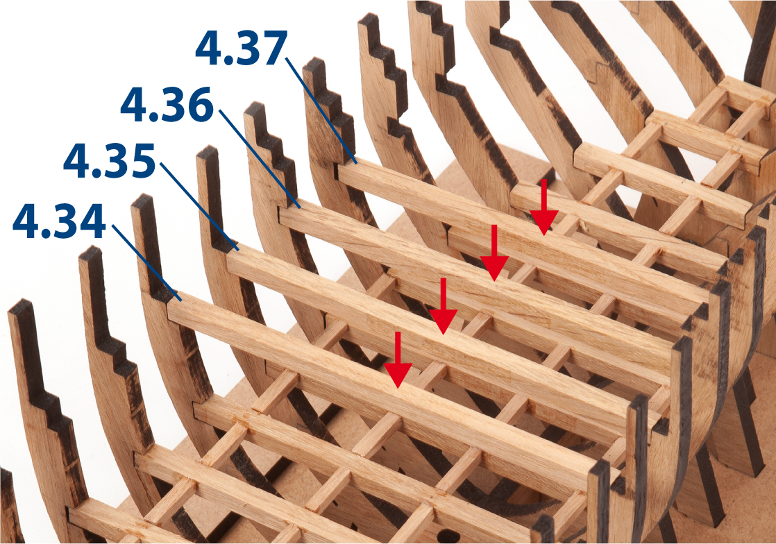
Step 14
Fit the parts 4.34 to 4.37 between the upper recesses of frames 32–35. Do not glue.
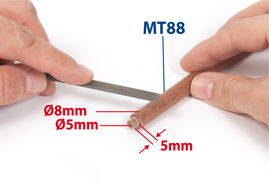
Step 15
Take a Ø8 mm mahogany rod and use a flat file to reduce the diameter at one end to Ø5 mm to form part MT88.
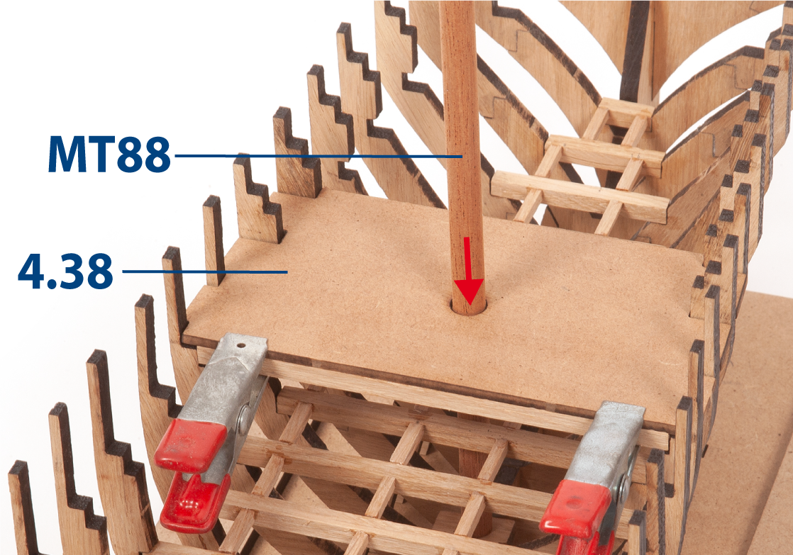
Step 16
Position part 4.38 between the frames and on the battens. Do not glue. Insert part MT88 to check its fit between the battens and into part 4.18.
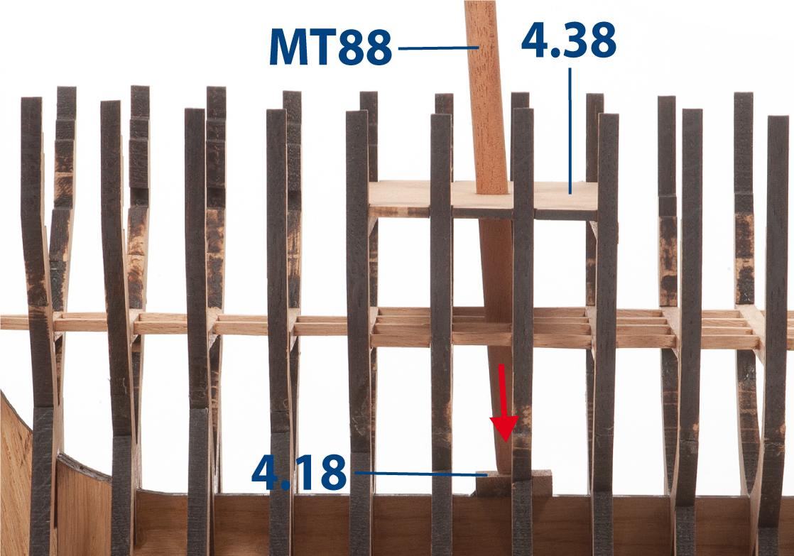
Step 17
This image shows the alignment of the parts.
Once part MT88 fits correctly in place, remove part MT88, part 4.38 and the battens, then set them aside.
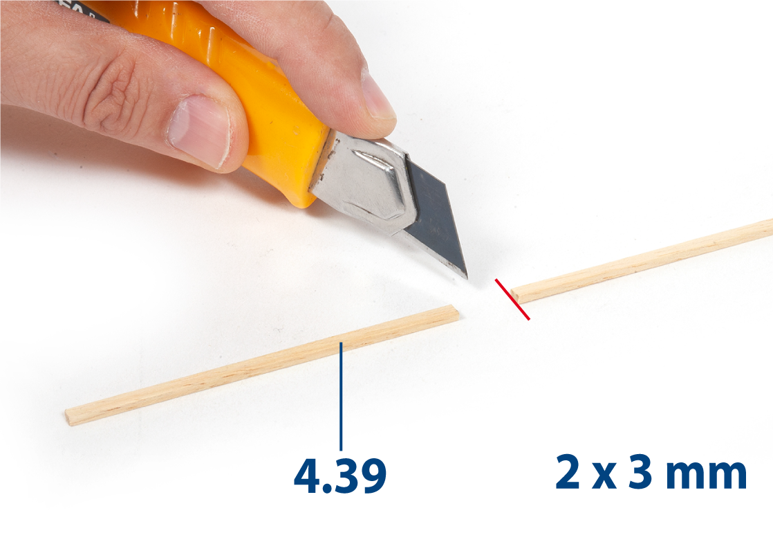
Step 1
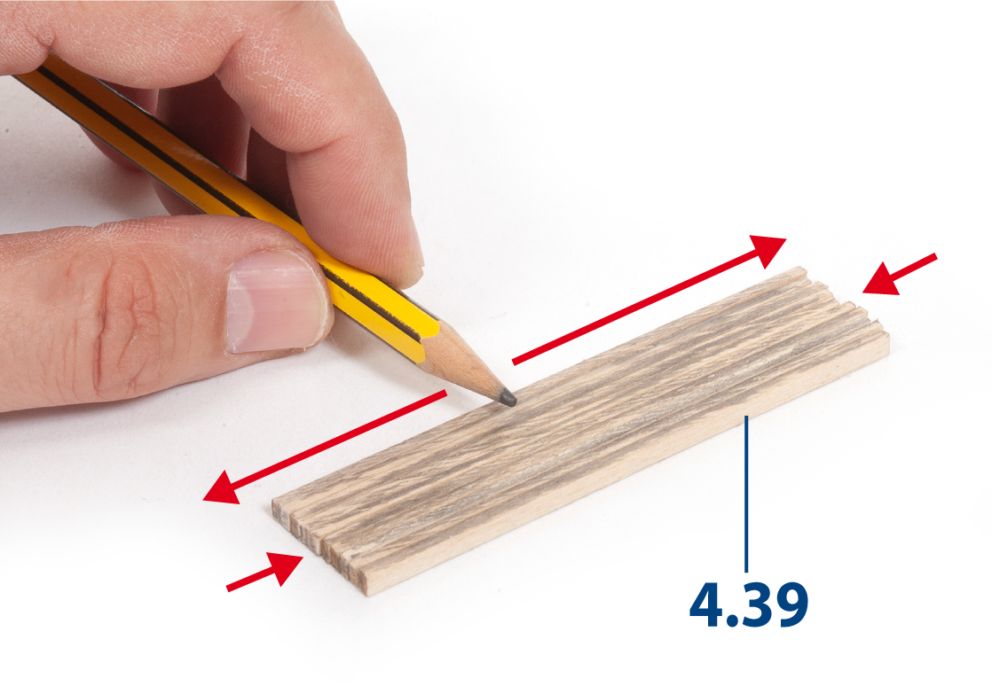
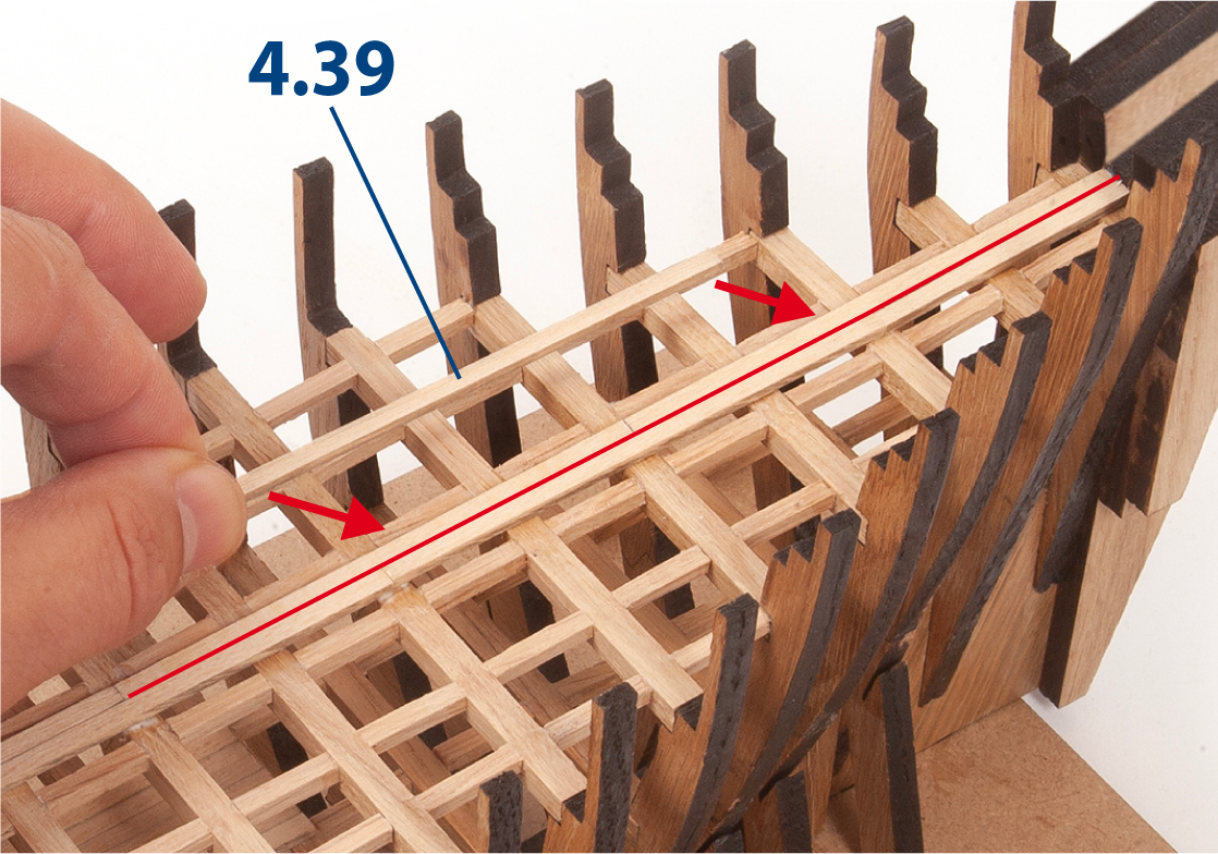
Sand a 2 x 3 mm lime wood strip with fine-grit sandpaper or a sanding sponge. Cut 24 parts 4.39 to size (2 x 3 x 80 mm). Make sure to cut as perpendicular as possible.
Step 2
Use a pencil to shade the 2 mm edges of each part 4.39.
Step 3
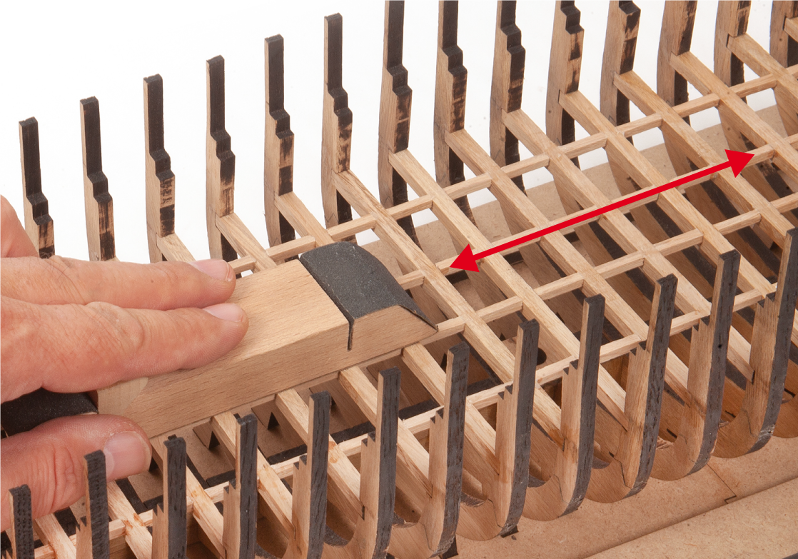
Sand the battens with a sanding block to level any unevenness.
Step 4
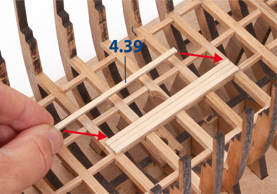
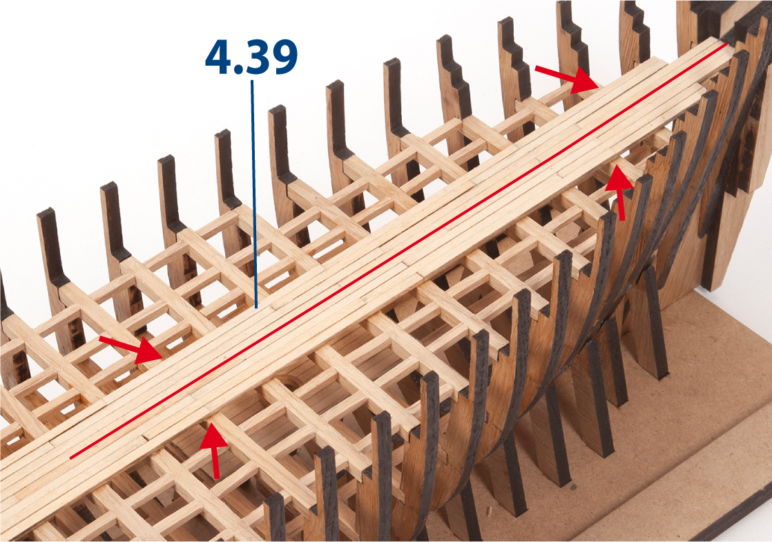
Glue four parts 4.39 between frames 8–12, as shown.
Step 5
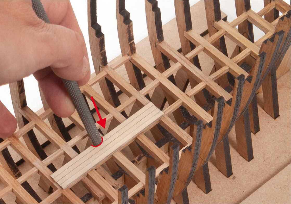
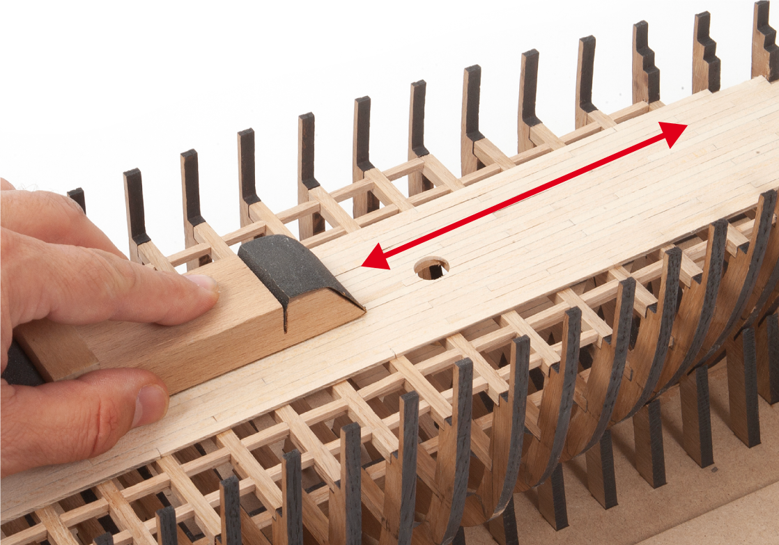
Use a round file to make an opening to fit part MT88.
Step 6
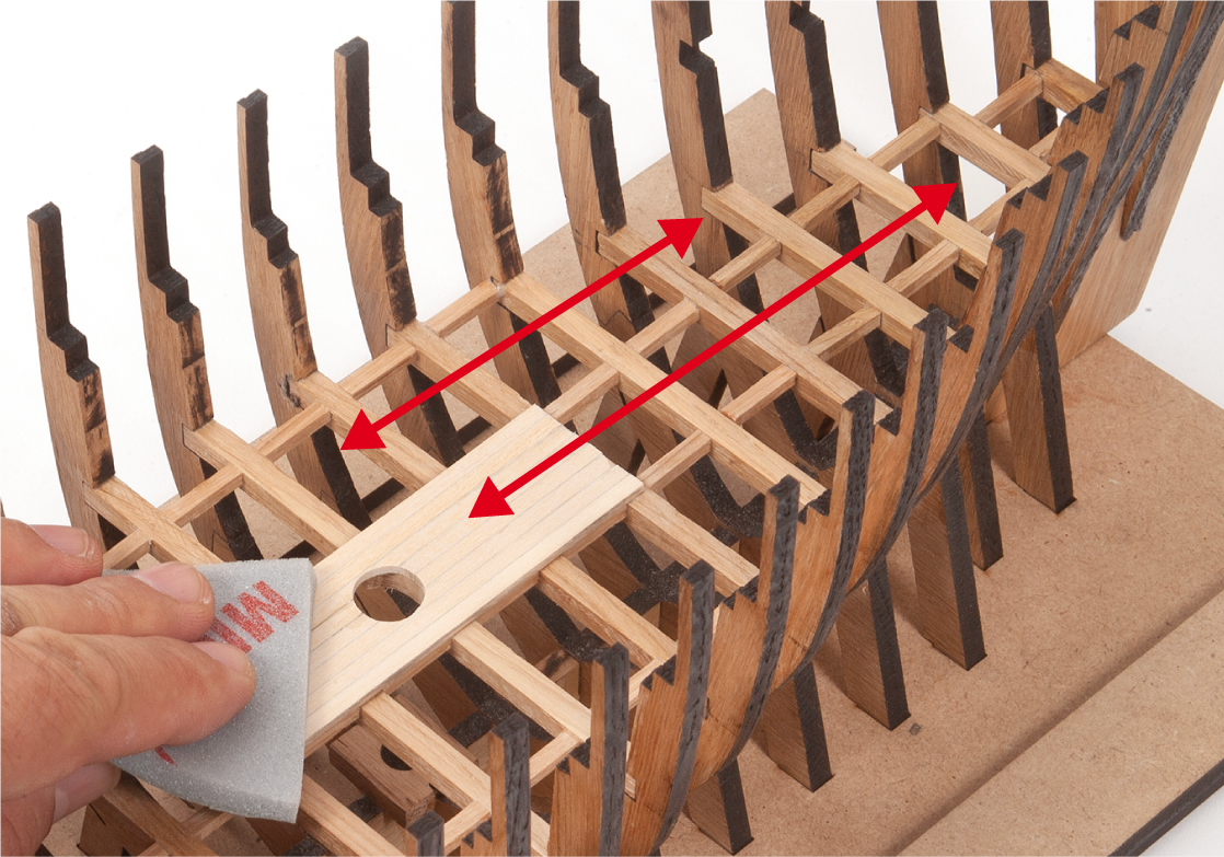
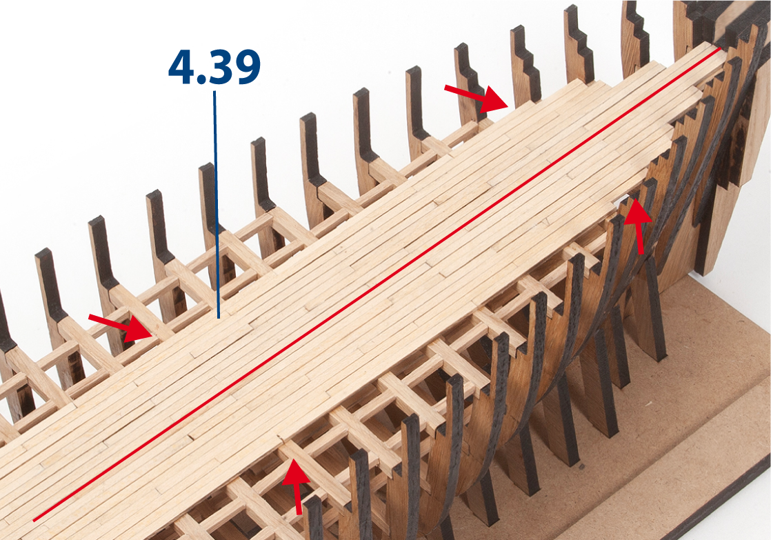
Glue four more parts 4.39 and complete the opening.
Sand the strips to even the surface, then smooth them with a fine-grit sanding sponge, as shown.
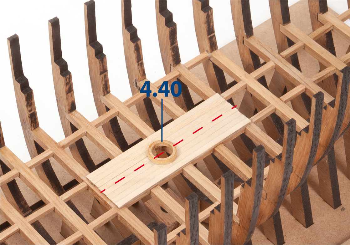
Step 7
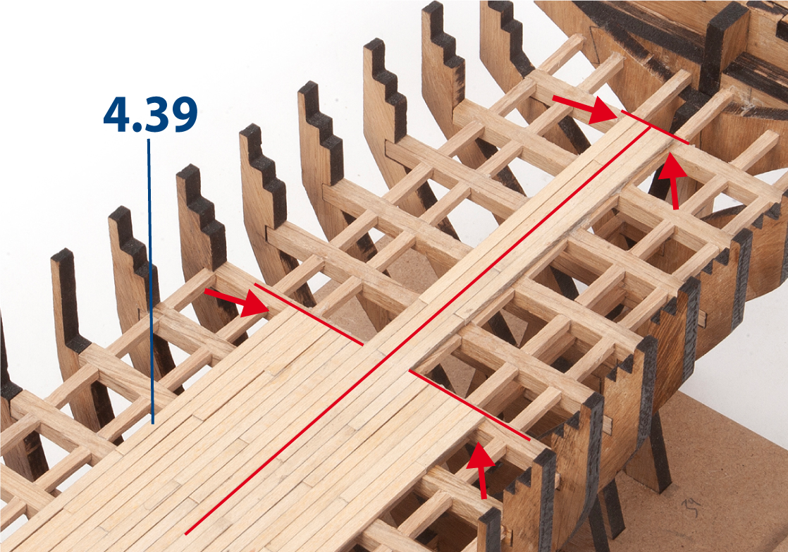
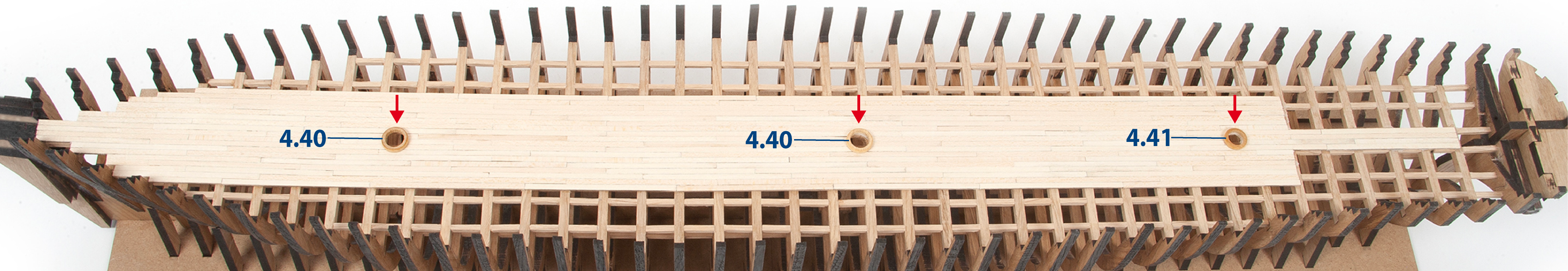
Centre and glue one part 4.40 over the opening for part MT88.
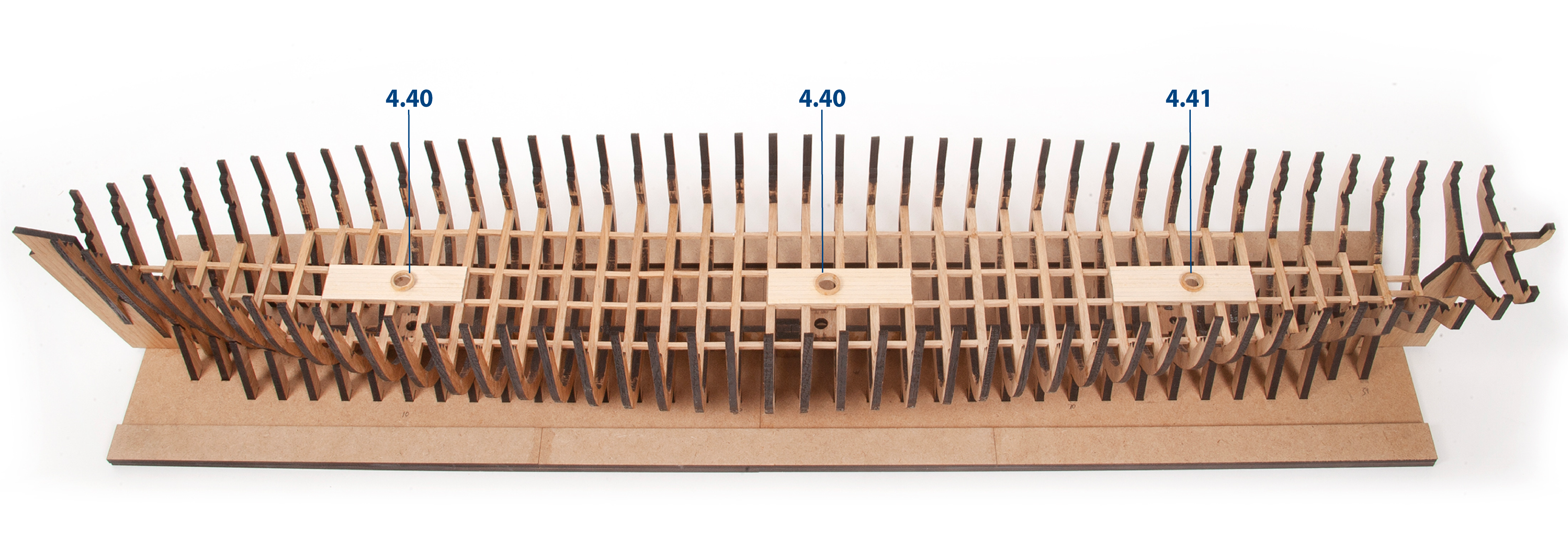
Step 8
Repeat the same procedure to fit and glue the remaining part 4.40 and part 4.41 over the openings for the other masts.
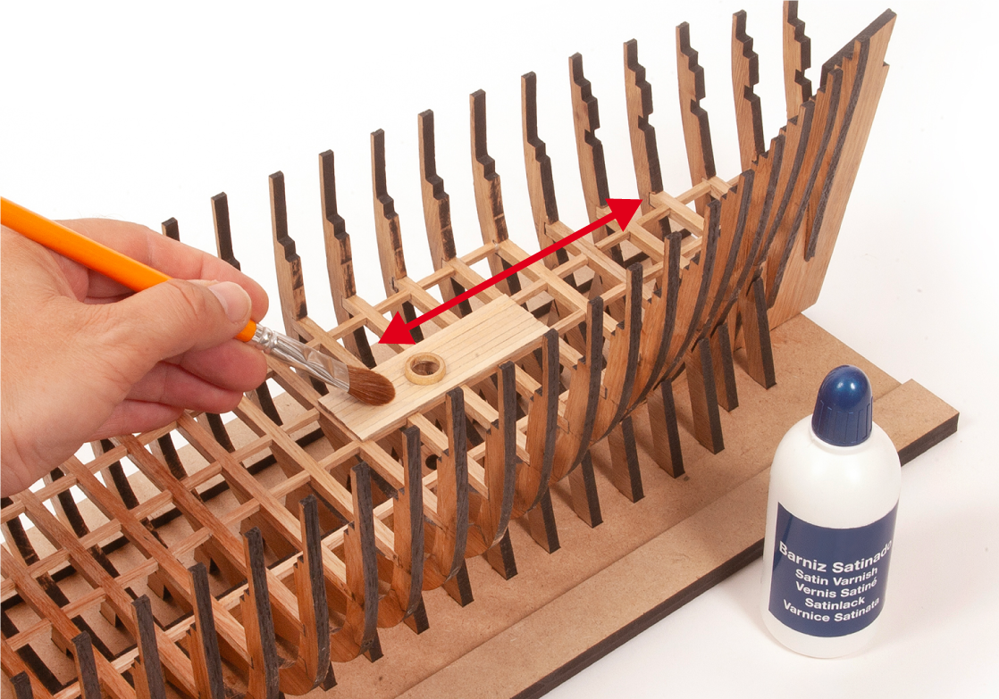
Step 1
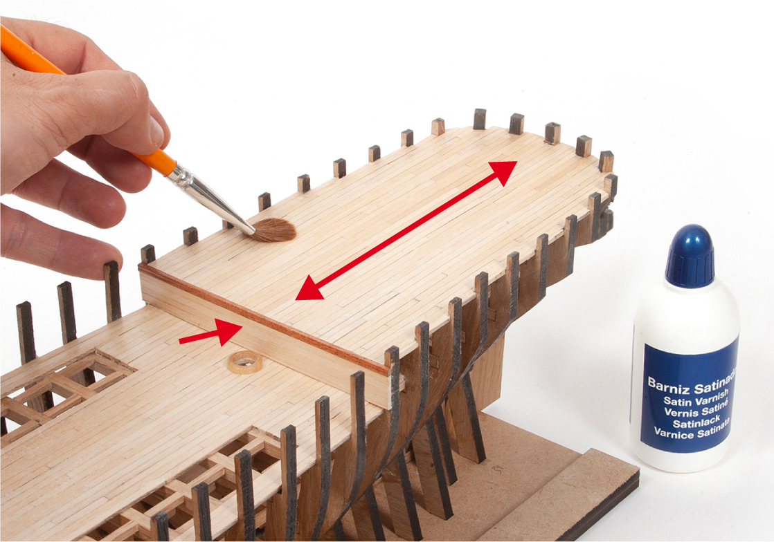
Apply clear varnish to all the wooden parts added to the structure.
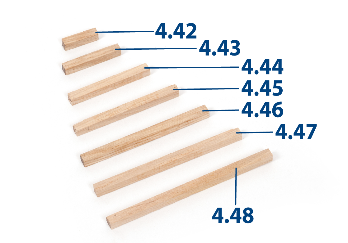
Step 2
Cut parts 4.42 to 4.48 from a 5 x 5 mm oak strip to the lengths shown below.
| 4.42 | 5 x 5 x 20 mm |
| 4.43 | 5 x 5 x 33 mm |
| 4.44 | 5 x 5 x 46 mm |
| 4.45 | 5 x 5 x 60 mm |
| 4.46 | 5 x 5 x 72 mm |
| 4.47 | 5 x 5 x 81 mm |
| 4.48 | 5 x 5 x 91 mm |
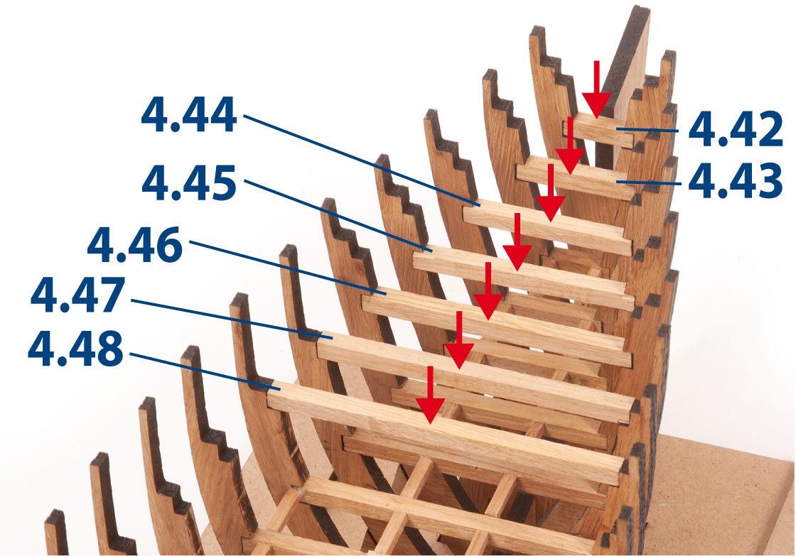
Step 3
Insert and glue the parts between the upper recesses, as shown.
Step 4
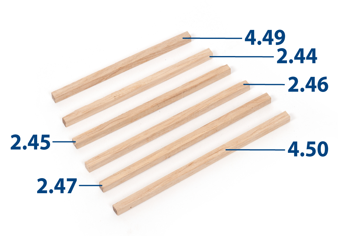
Cut parts 4.49 and 4.50 and parts 2.44 to 2.47 from a 5 x 5 mm oak strip to the lengths shown below.
| 4.49 | 5 x 5 x 98 mm |
| 4.50 | 5 x 5 x 122 mm |
| 2.44 | 5 x 5 x 106 mm |
| 2.45 | 5 x 5 x 110 mm |
| 2.46 | 5 x 5 x 114 mm |
| 2.47 | 5 x 5 x 119 mm |
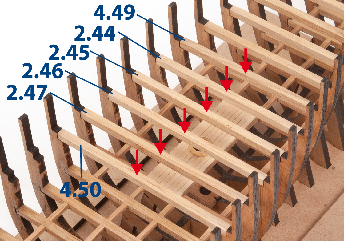
Step 5
Insert and glue the parts between the upper recesses, as shown.
Step 6
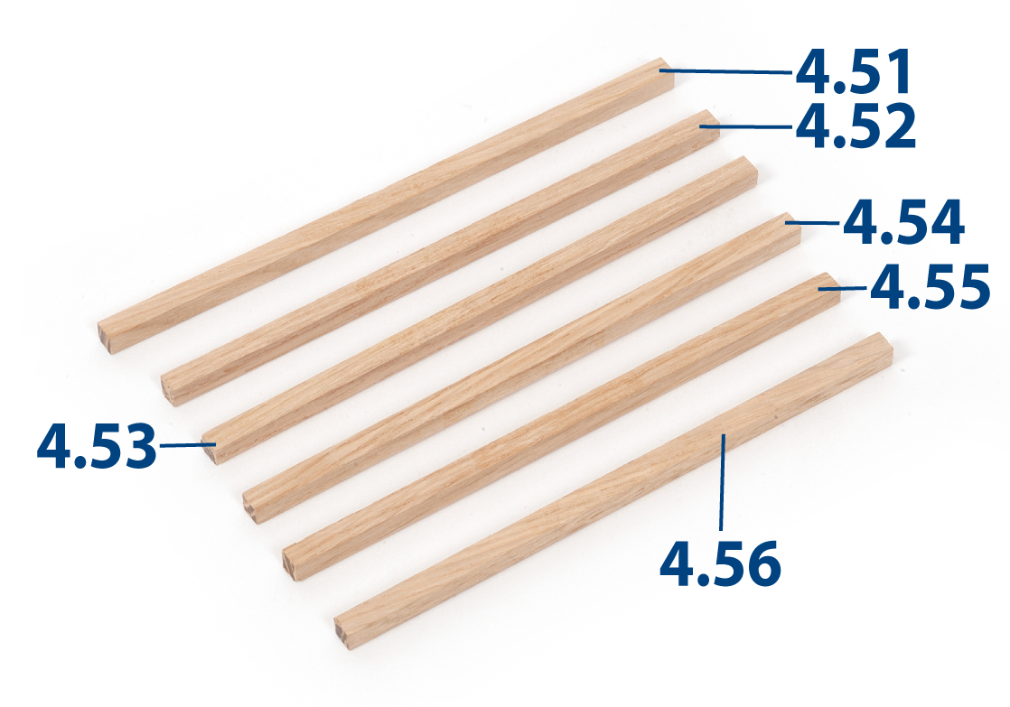
Cut parts 4.51 to 4.56 from a 5 x 5 mm oak strip to the lengths shown below.
| 4.51 | 5 x 5 x 123 mm |
| 4.52 | 5 x 5 x 125 mm |
| 4.53 | 5 x 5 x 127 mm |
| 4.54 | 5 x 5 x 128 mm |
| 4.55 | 5 x 5 x 129 mm |
| 4.56 | 5 x 5 x 133 mm |
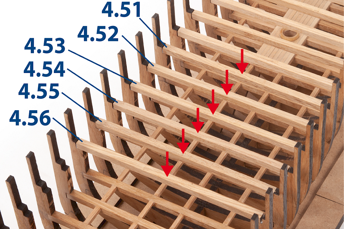
Step 7
Insert and glue the parts between the upper recesses, as shown.
Step 8
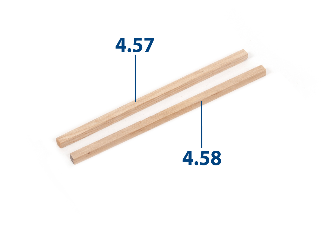
Cut parts 4.57 and 4.58 from a 5 x 5 mm oak strip to the lengths shown below.
| 4.57 | 5 x 5 x 130 mm |
| 4.58 | 5 x 5 x 125 mm |
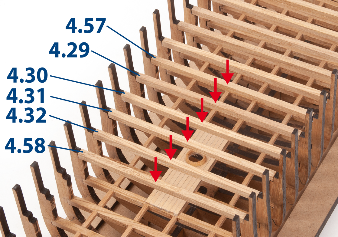
Step 9
Insert and glue the parts 4.57 and 4.58 as well as the battens from stage 12, step 9, between the upper recesses, as shown in the image.
Step 10
Cut parts 4.59 and 4.60 from a 5 x 5 mm oak strip to the lengths shown below.
| 4.59 | 5 x 5 x 124 mm |
| 4.60 | 5 x 5 x 123 mm |
Step 11
Cut parts 4.61 to 4.64 from a 5 x 5 mm oak strip to the lengths shown below.
| 4.61 | 5 x 5 x 121 mm |
| 4.62 | 5 x 5 x 120 mm |
| 4.63 | 5 x 5 x 118 mm |
| 4.64 | 5 x 5 x 116 mm |

Step 12
Insert and glue parts 4.59 to 4.63 between the upper recesses, as shown in the image.
Step 13
Insert and glue part 4.64 as well as parts 4.34, 4.35, 4.36 and 4.37 from stage 12, step 13, between the upper recesses, as shown in the image.
Step 14
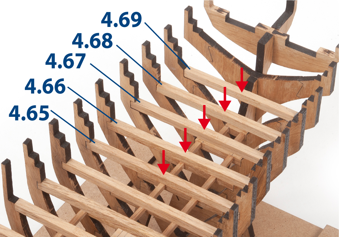
Cut parts 4.65 to 4.69 from a 5 x 5 mm oak strip to the lengths shown below.
| 4.65 | 5 x 5 x 100 mm |
| 4.66 | 5 x 5 x 97 mm |
| 4.67 | 5 x 5 x 94 mm |
| 4.68 | 5 x 5 x 86 mm |
| 4.69 | 5 x 5 x 74 mm |
Step 15
Insert and glue the parts between the upper recesses, as shown.
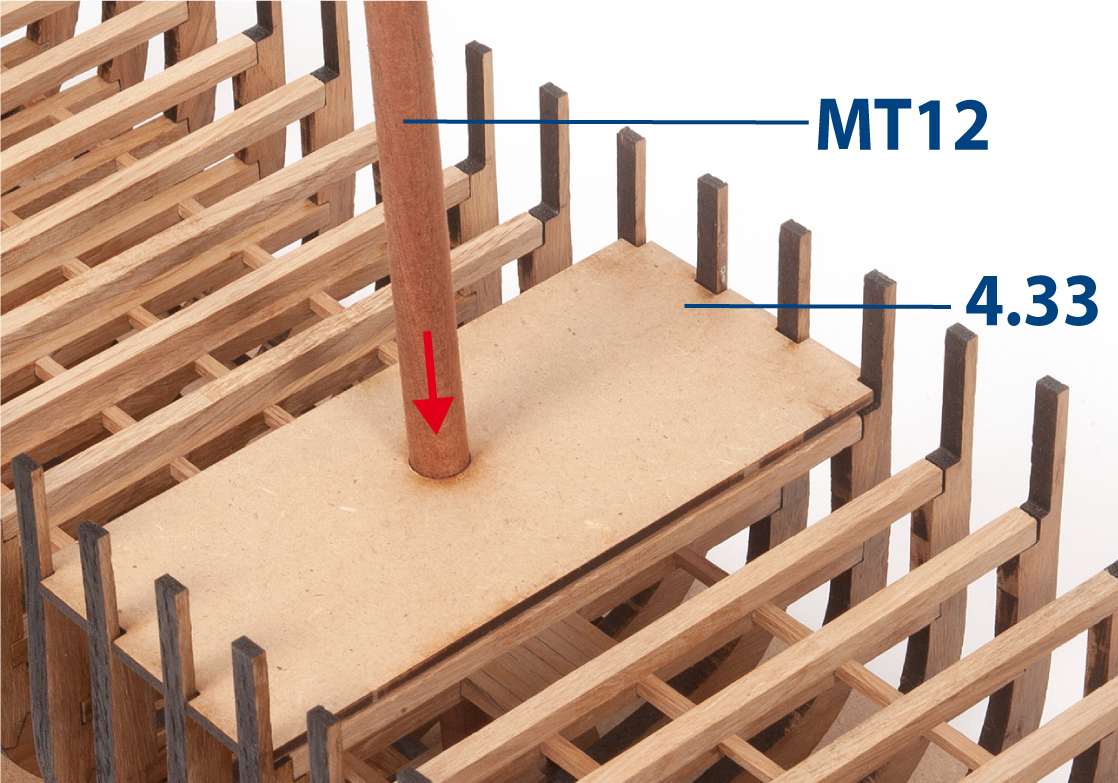
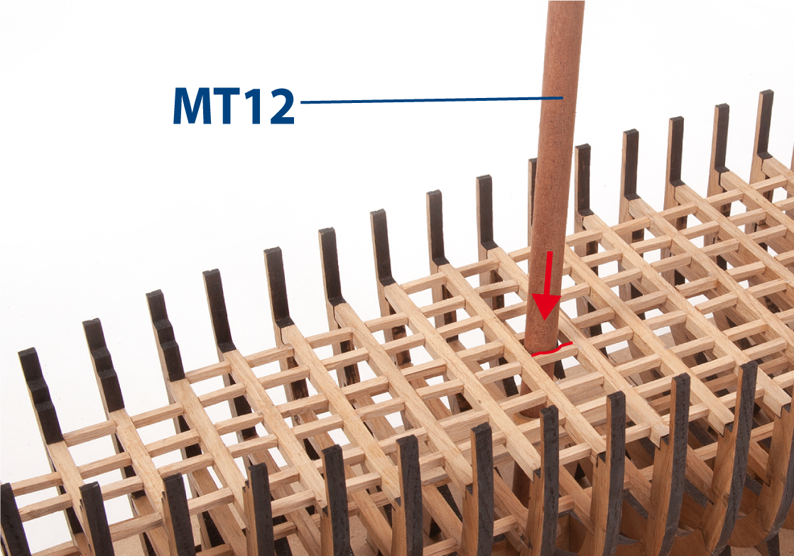
Step 16
Position part 4.33 between the frames and on the battens. Do not glue. Insert part MT12 to check its fit.
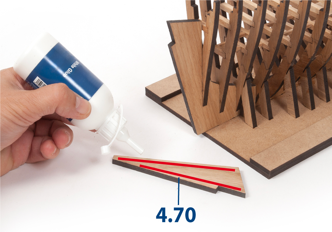
Step 1
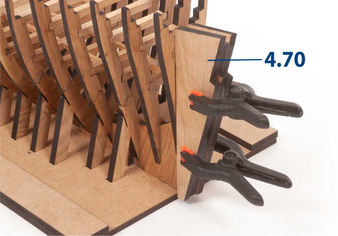
Apply white glue to one side of part 4.70.
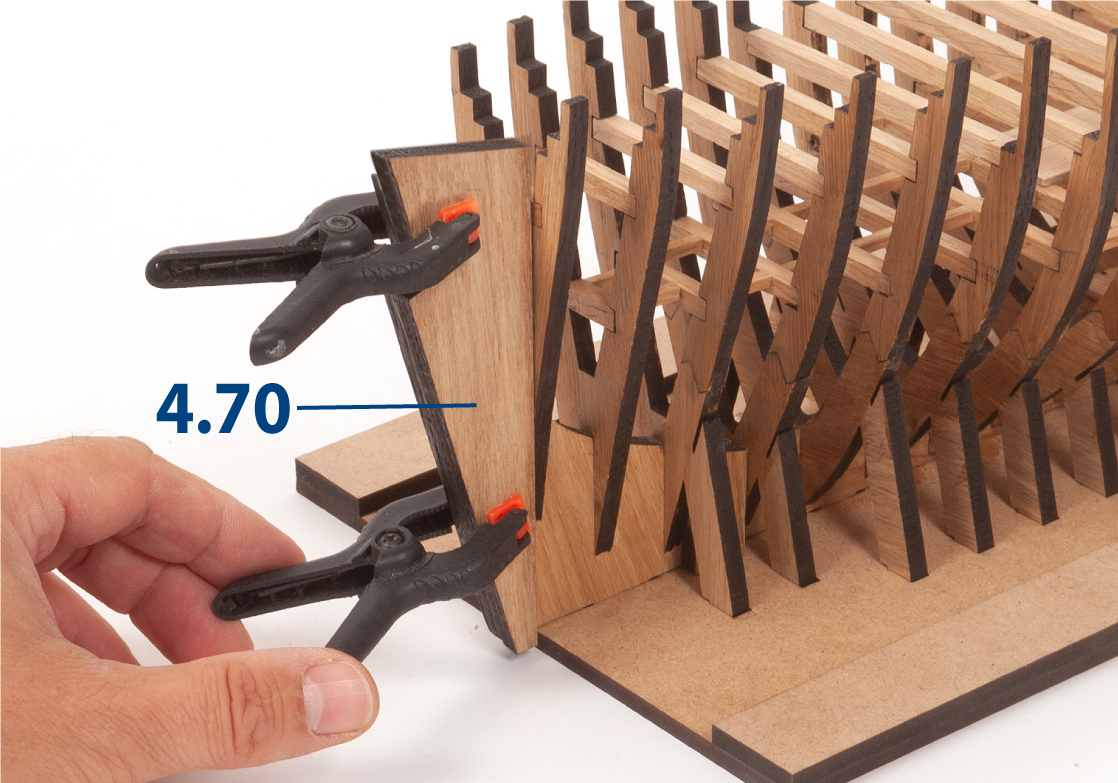
Step 2
Glue part 4.70 against the false keel and frame 1, as shown. Hold the part in place with clamps until the glue dries.
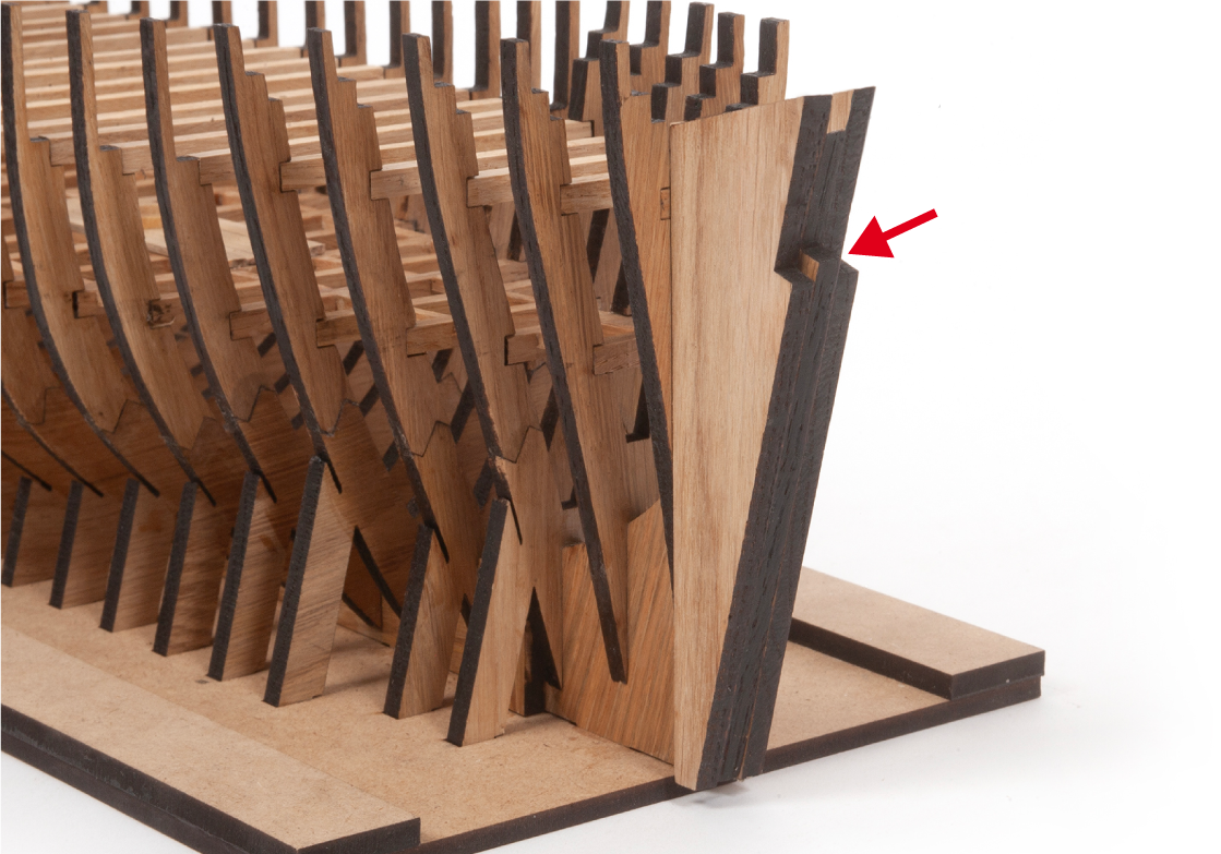
Step 3
Repeat the same procedure to glue the second part 4.70 to the opposite side of the false keel.
Step 4
Remove the clamps once the glue has dried.
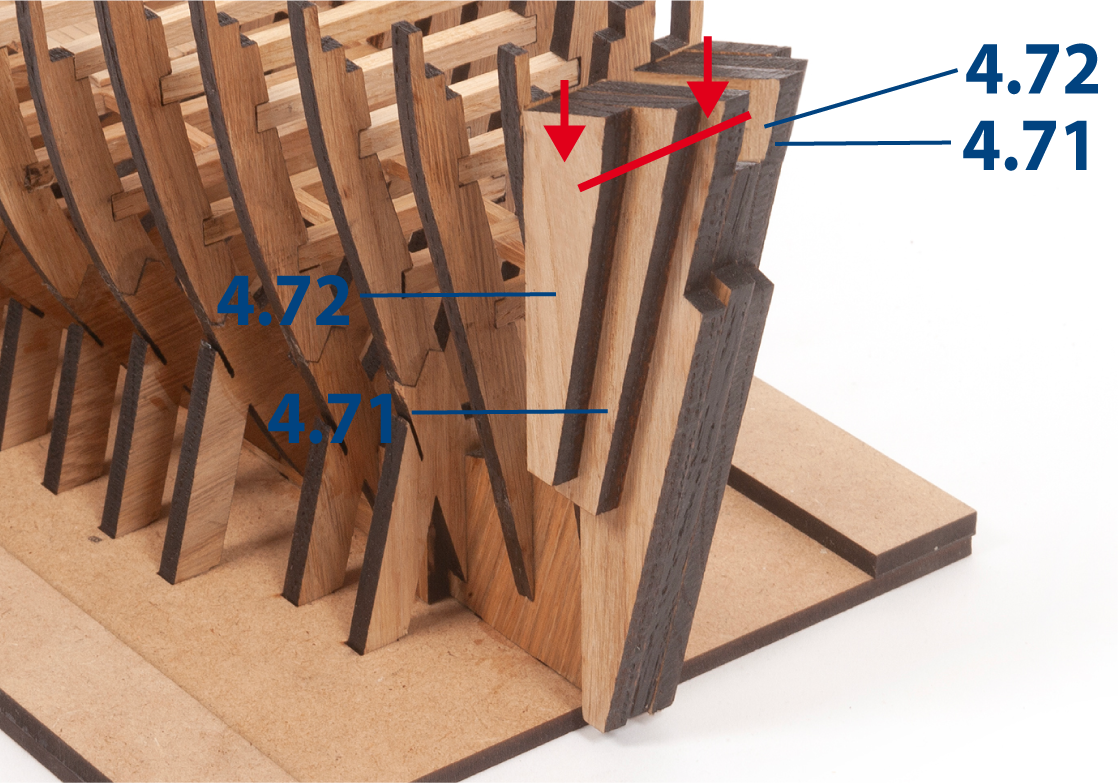
Step 5
Glue parts 4.71 and 4.72 to each side of the structure, as shown.
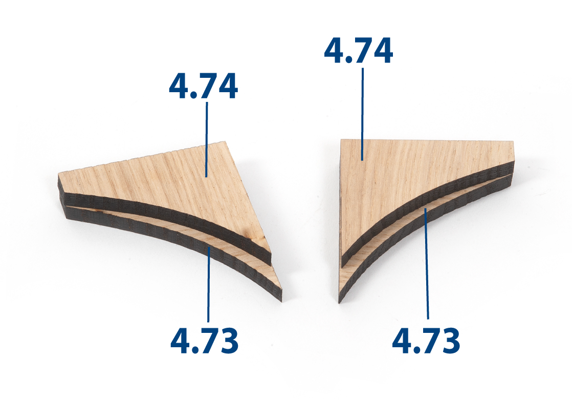
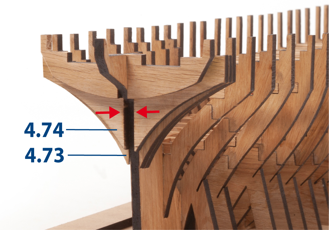
Step 6
Glue parts 4.73 and 4.74 together, aligning their straight edges.
Step 7
Glue these assemblies to frame 41, as shown.
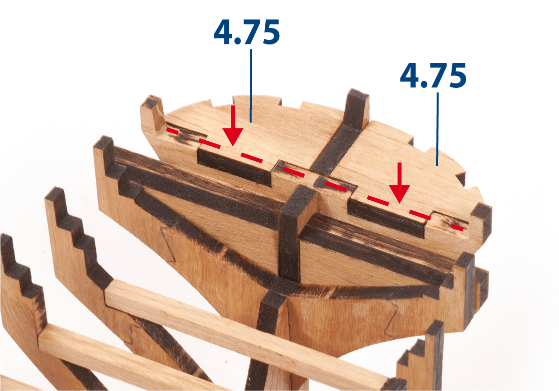
Step 8
Glue parts 4.75 to the last frame and the false keel.
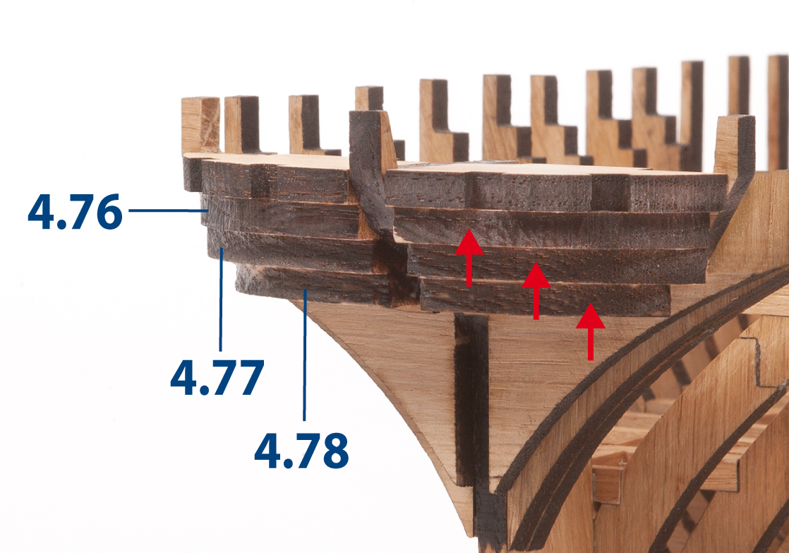
Step 9
Glue parts 4.76 to 4.78 to both sides of the structure.
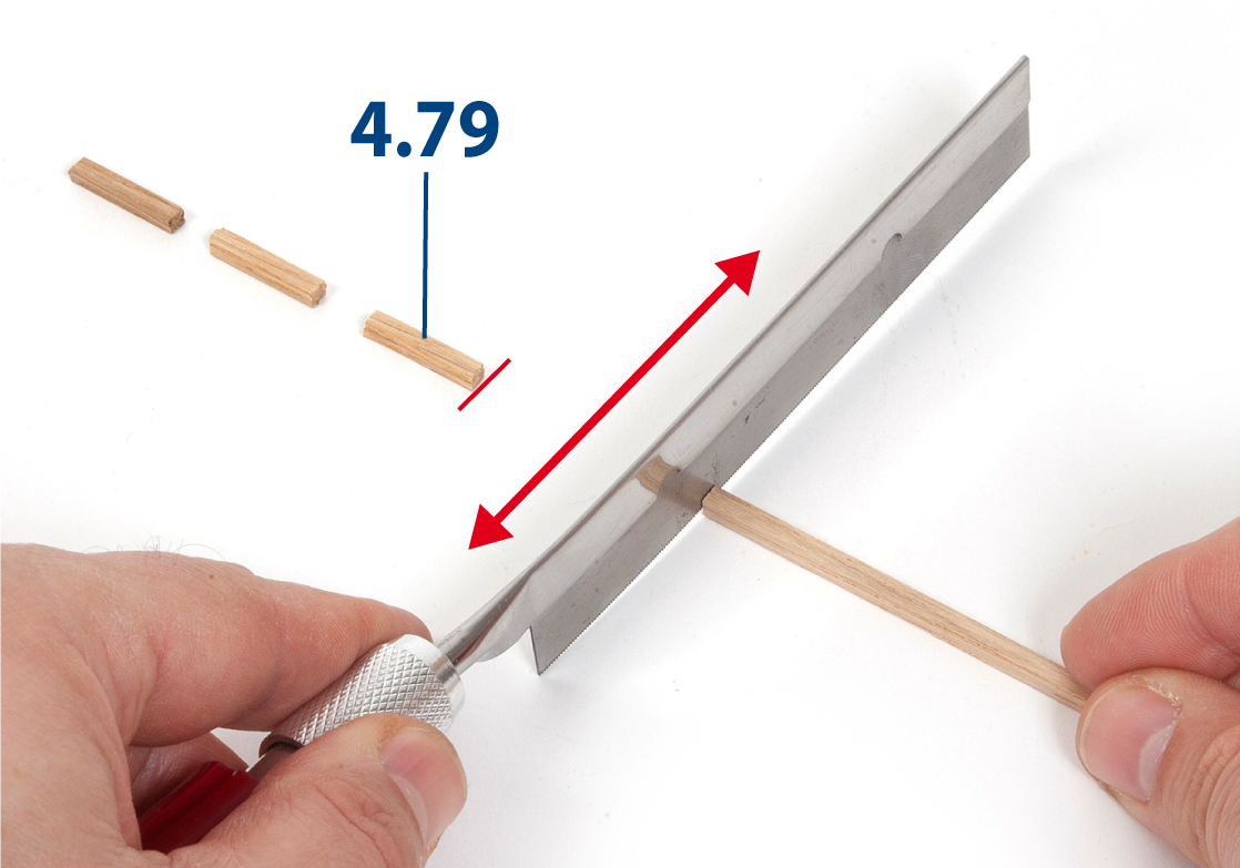
Step 10
Sand several 3 x 3 mm oak strips with fine-grit sandpaper or a sanding sponge. Cut parts 4.79 to length (3 x 3 x 15 mm).
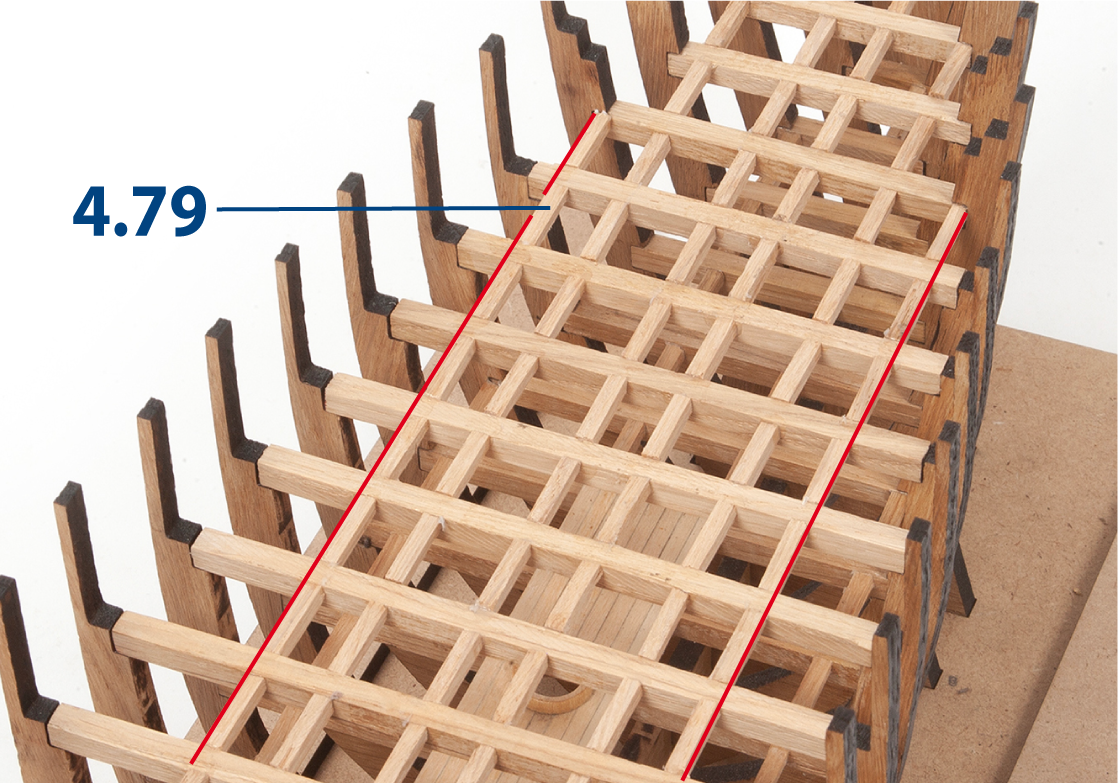
Step 11
Glue parts 4.79 between the deck beams, starting from frame 1 and continuing towards the stern.
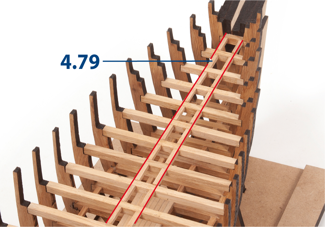
Step 12
Continue gluing parts 4.79 until reaching the end of the hull. Complete with two parts 4.80 (3 x 3 x 20 mm) as shown.
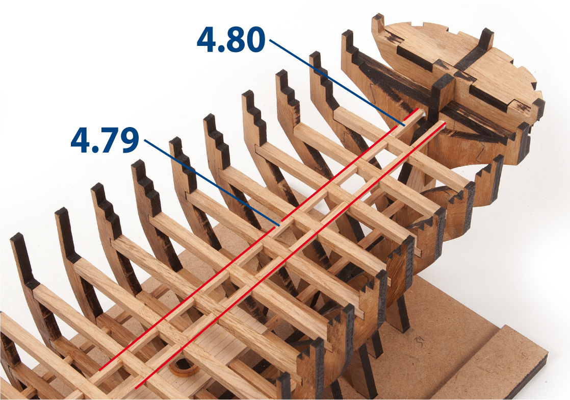
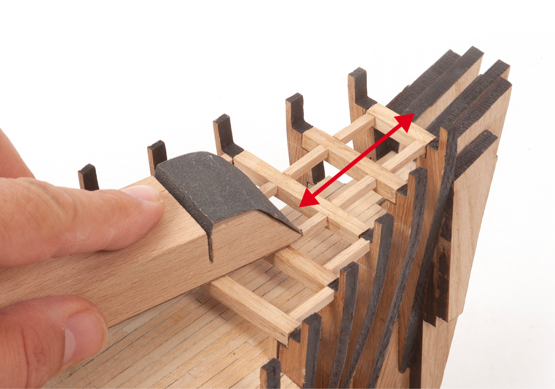
Step 13
Glue another row of parts 4.79 on each side, as shown in the image.
Step 14
Continue gluing both rows of parts 4.79 to the end of the hull.
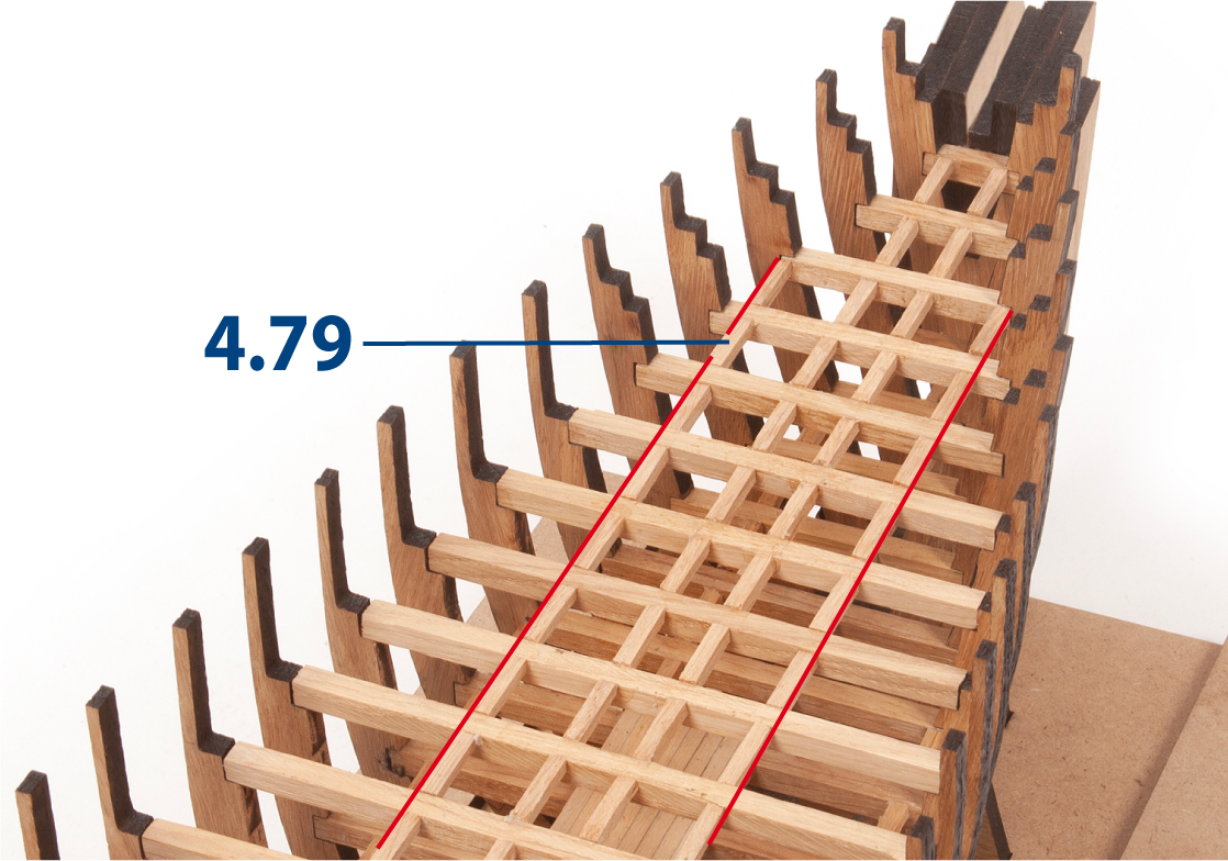
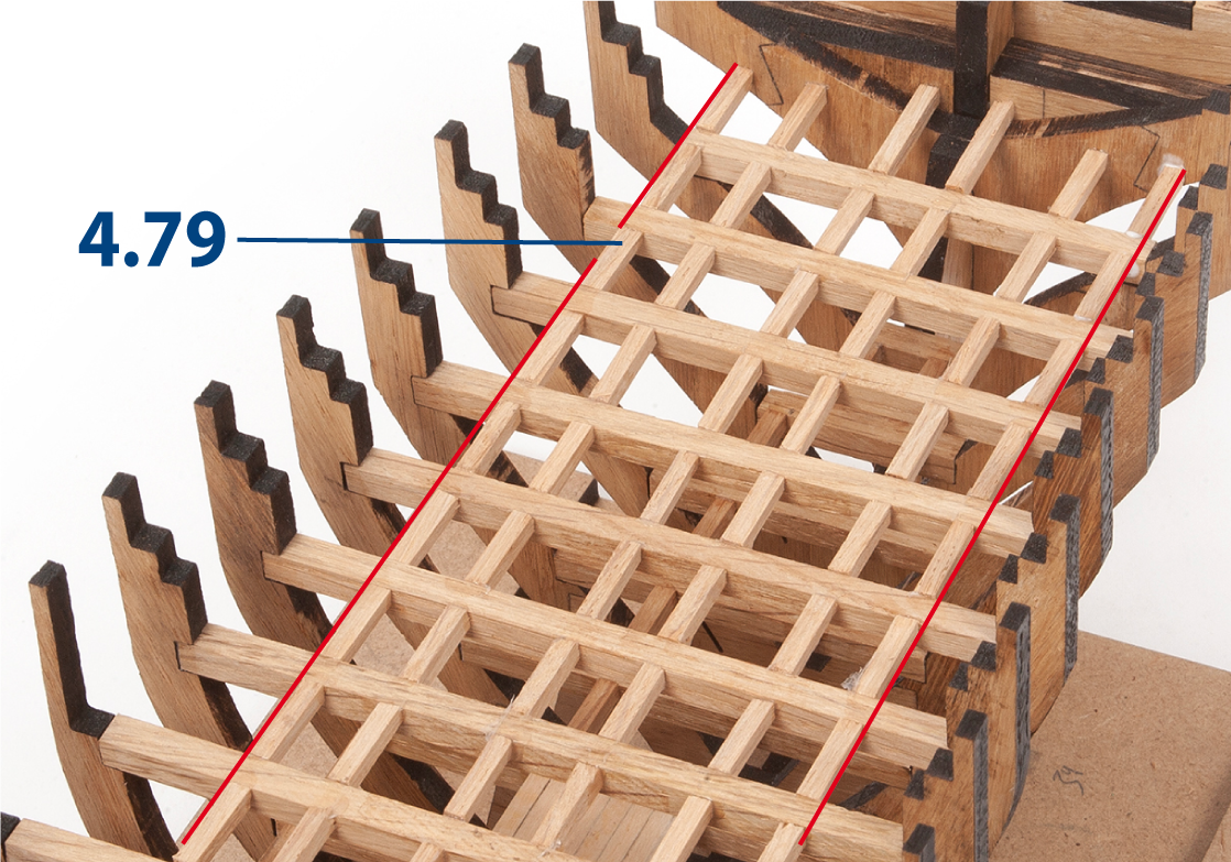
Step 15
Glue two additional rows of parts 4.79, as shown in the image.
Step 16
Continue gluing both rows of parts 4.79 to the end of the hull.
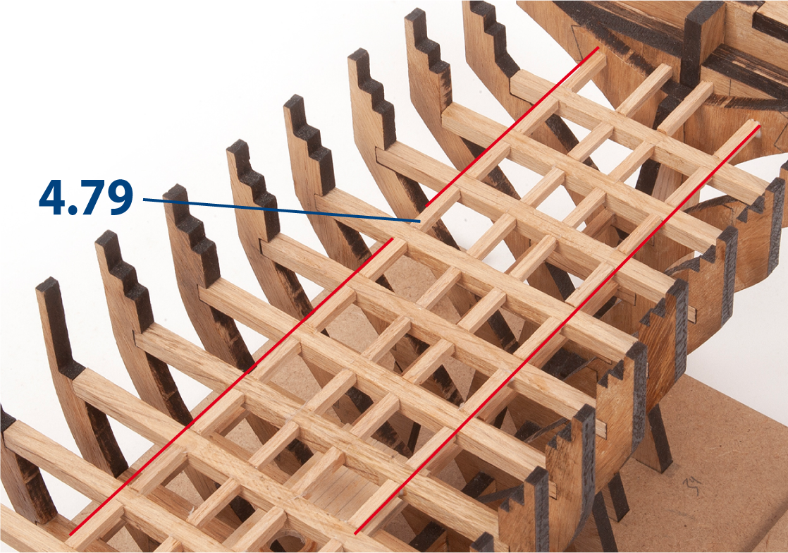
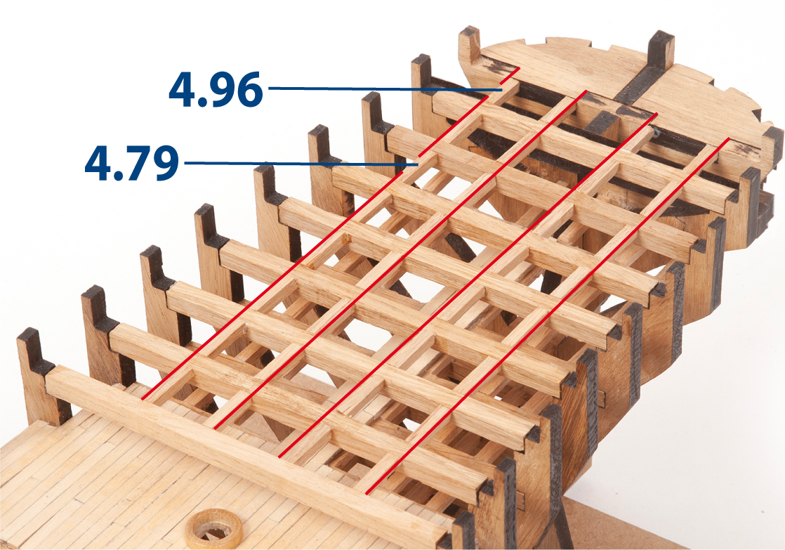
Step 17
Glue two additional rows of parts 4.79 from frame 9, as shown.
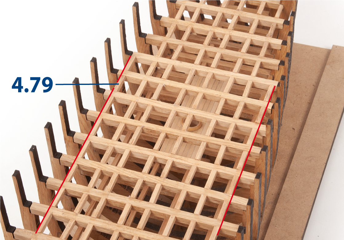
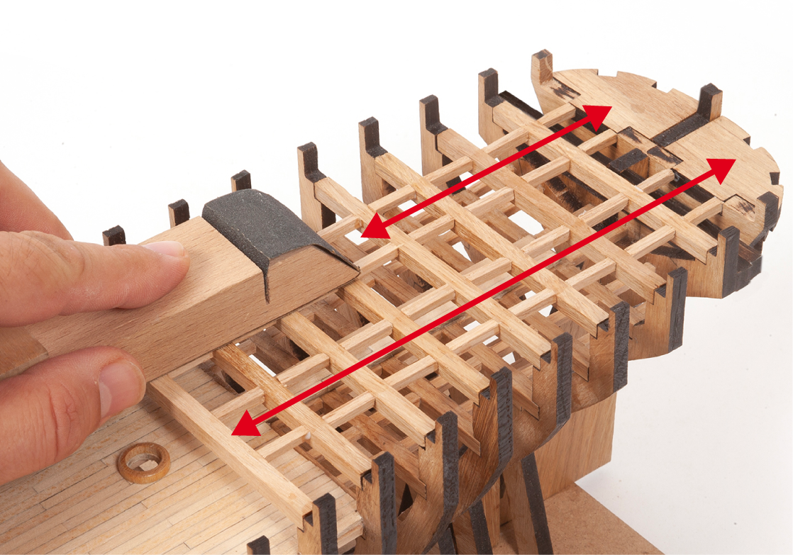
Step 18
Continue gluing both rows of parts 4.79 up to frame 35.
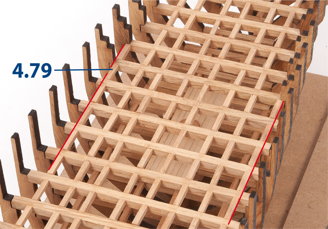
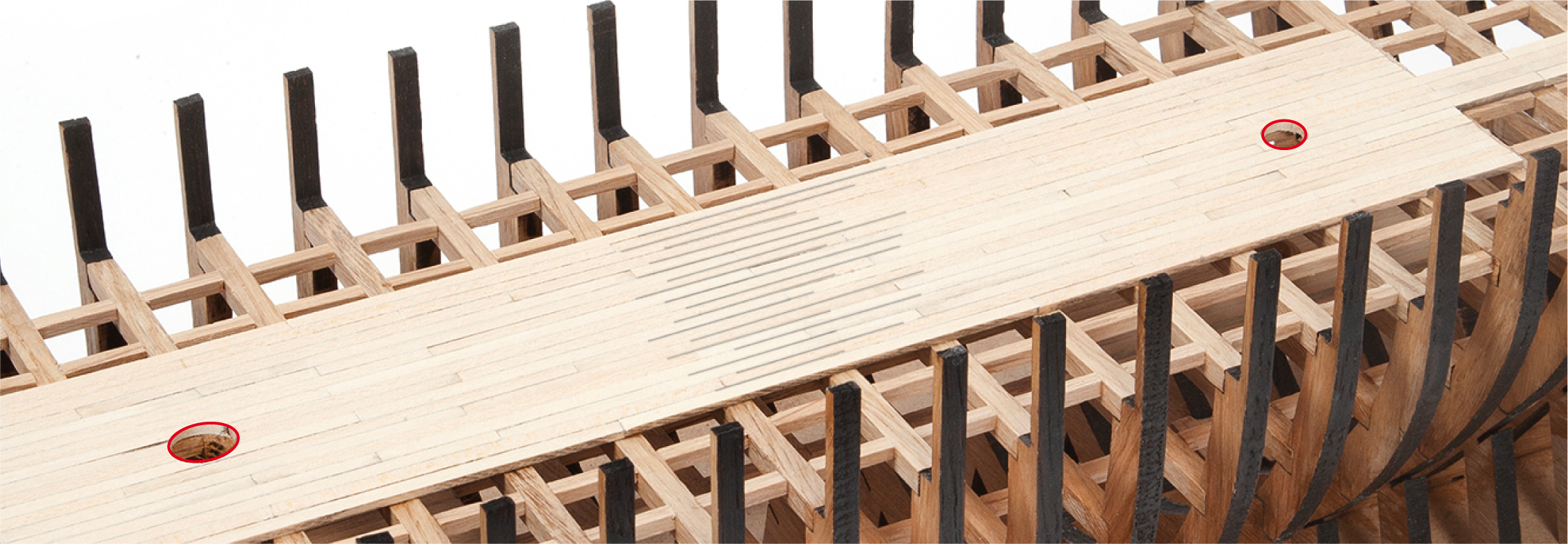
Step 19
This image shows the eight rows of parts 4.79.
Step 1
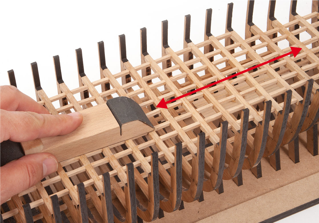
Sand the surface with a sanding block to level any unevenness.
Step 2
Position part 2.48 to check the fit of part MT12. Adjust the opening if necessary.
Step 3
Repeat the same procedure to check and adjust the fit of parts MT57 and MT88.
Step 4
Cut parts 4.39 (2 x 3 x 80 mm lime wood). Glue two rows of parts 4.39, as shown.
Step 5
Continue gluing parts 4.39, as shown.
Step 6
This image shows how the parts should fit in the stern area.
Step 1
Position part 4.33 on the deck and use a round file to make the opening for the foremast.
Step 2
Repeat the same procedure to make the openings for the other masts.
Step 3
Sand the deck with a sanding block to level any unevenness.
Step 4
Glue parts 4.40 and 4.41 over the mast openings, as shown.
Step 5
Glue parts 4.39 (2 x 3 x 80 mm lime wood) and 4.81 (2 x 3 x 600 mm lime wood), as shown in the image.
Step 6
Sand the added parts in the bow area to even the surfaces.
Step 7
Repeat the same procedure in the stern area.
Step 8
Varnish the deck and the added parts.
Step 1
Cut parts 4.82 to 4.86 from a 5 x 5 mm oak strip to the lengths shown below.
| 4.82 | 5 x 5 x 24 mm |
| 4.83 | 5 x 5 x 37 mm |
| 4.84 | 5 x 5 x 50 mm |
| 4.85 | 5 x 5 x 64 mm |
| 4.86 | 5 x 5 x 76 mm |
Step 2
Glue parts 4.82 to 4.86.
Step 3
Cut parts 4.87 to 4.94 from a 5 x 5 mm oak strip to the lengths shown below.
| 4.87 | 5 x 5 x 108 mm |
| 4.88 | 5 x 5 x 104 mm |
| 4.89 | 5 x 5 x 100 mm |
| 4.90 | 5 x 5 x 97 mm |
| 4.91 | 5 x 5 x 94 mm |
| 4.92 | 5 x 5 x 92 mm |
| 4.93 | 5 x 5 x 88 mm |
| 4.94 | 5 x 5 x 85 mm |
Step 4
Glue parts 4.87 to 4.94.
Step 5
Cut parts 4.79 and 4.95 from a 3 x 3 mm lime wood strip to the lengths shown below. Glue the parts as shown.
| 4.79 | 3 x 3 x 15 mm |
| 4.95 | 3 x 3 x 9 mm |
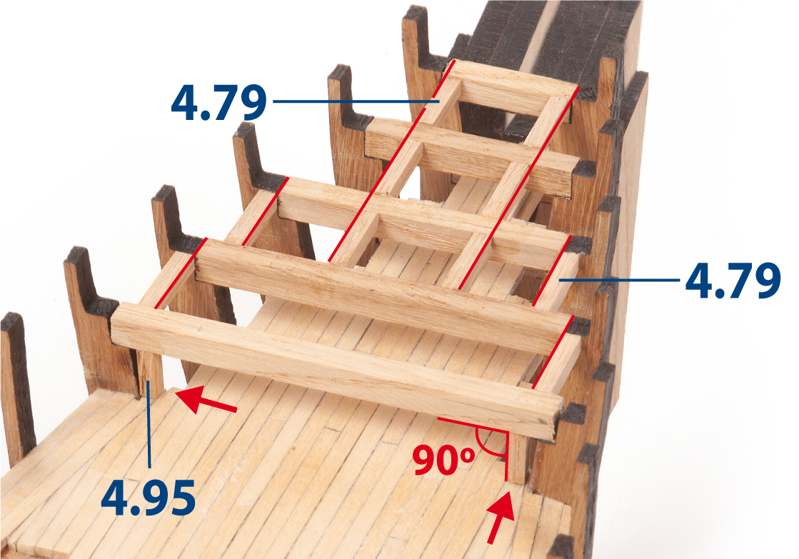
Step 6
Sand the surfaces with a sanding block.
Step 7
Cut and glue parts 4.79 and 4.96, as shown.
| 4.79 | 3 x 3 x 15 mm |
| 4.96 | 3 x 3 x 11 mm |
Step 8
Sand the surfaces with a sanding block.
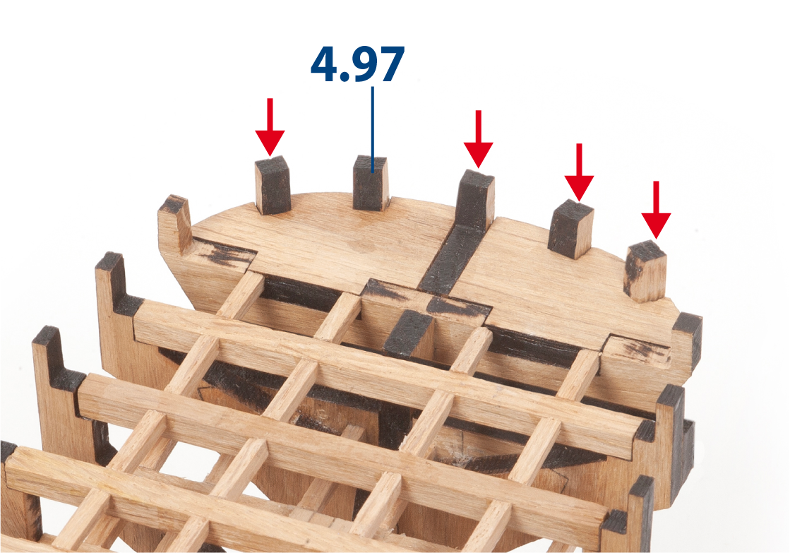
Step 9
Glue parts 4.97 (from pack 1) in the stern area of the hull.
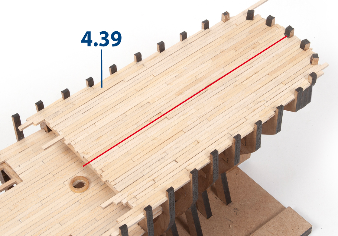
Step 10
Cut and glue parts 4.39 (2 x 3 x 80 mm lime wood) to plank the poop deck.
Step 11
Trim the excess planking and sand it flush with the outside of the frames.
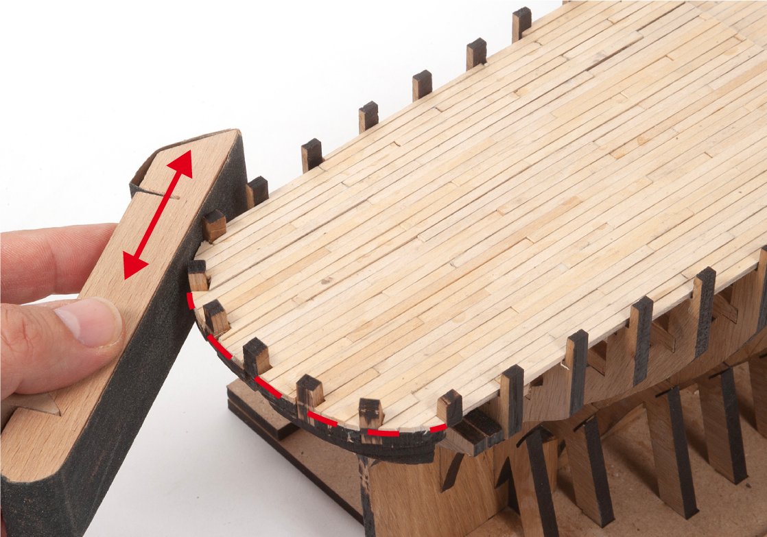
Step 12
Sand the poop deck to smooth the surface of the planking.
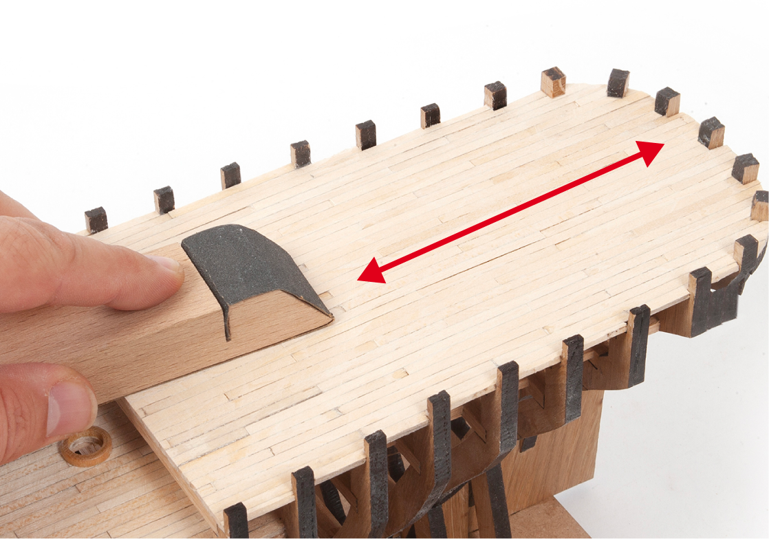
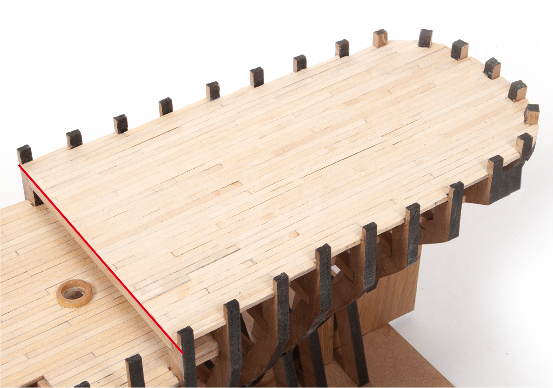
Step 13
The planking must be flush with the deck beam.
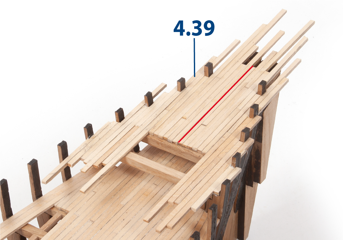
Step 14
Cut and glue parts 4.39 (2 x 3 x 80 mm lime wood) to plank the forecastle deck.
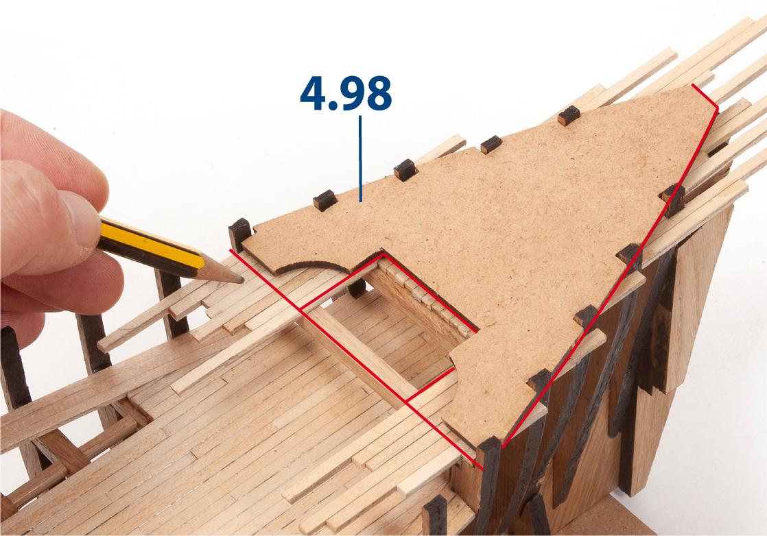
Step 15
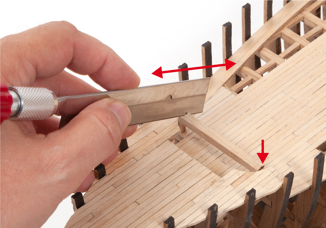
Position part 4.98 on the forecastle deck planking and trace around it with a pencil.
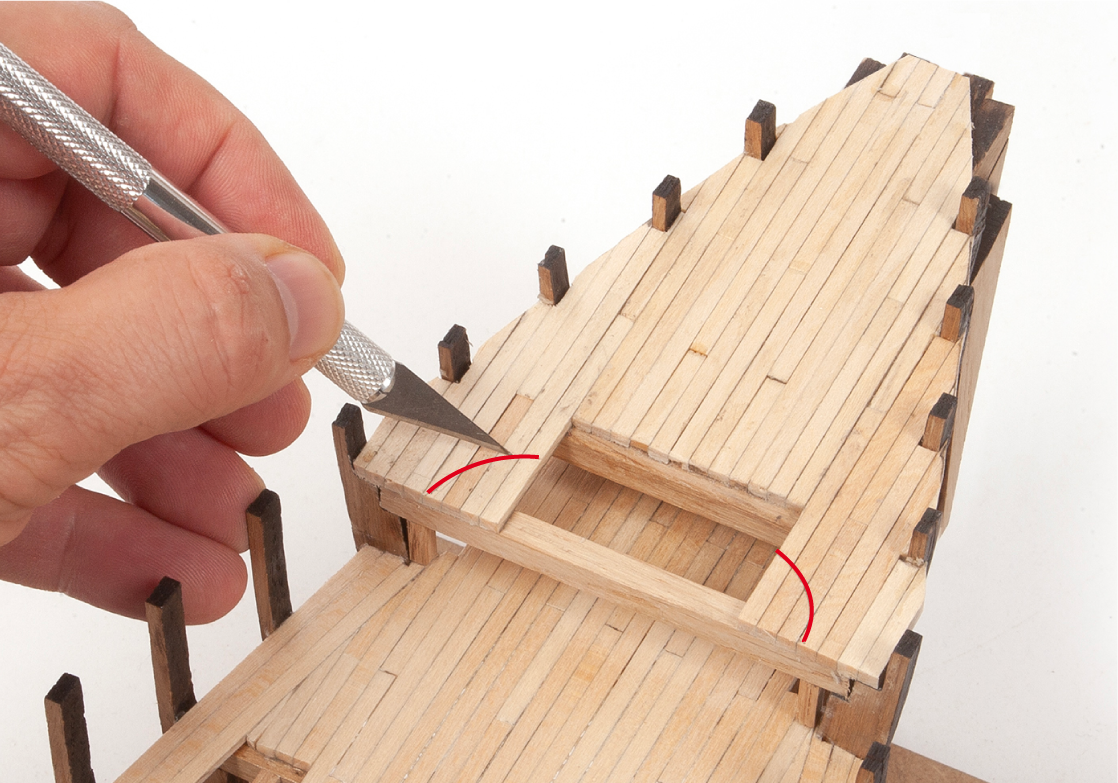
Step 16
Use a craft knife to remove the excess planking along the marked outline.
Step 17
Trim the deck beam as shown.
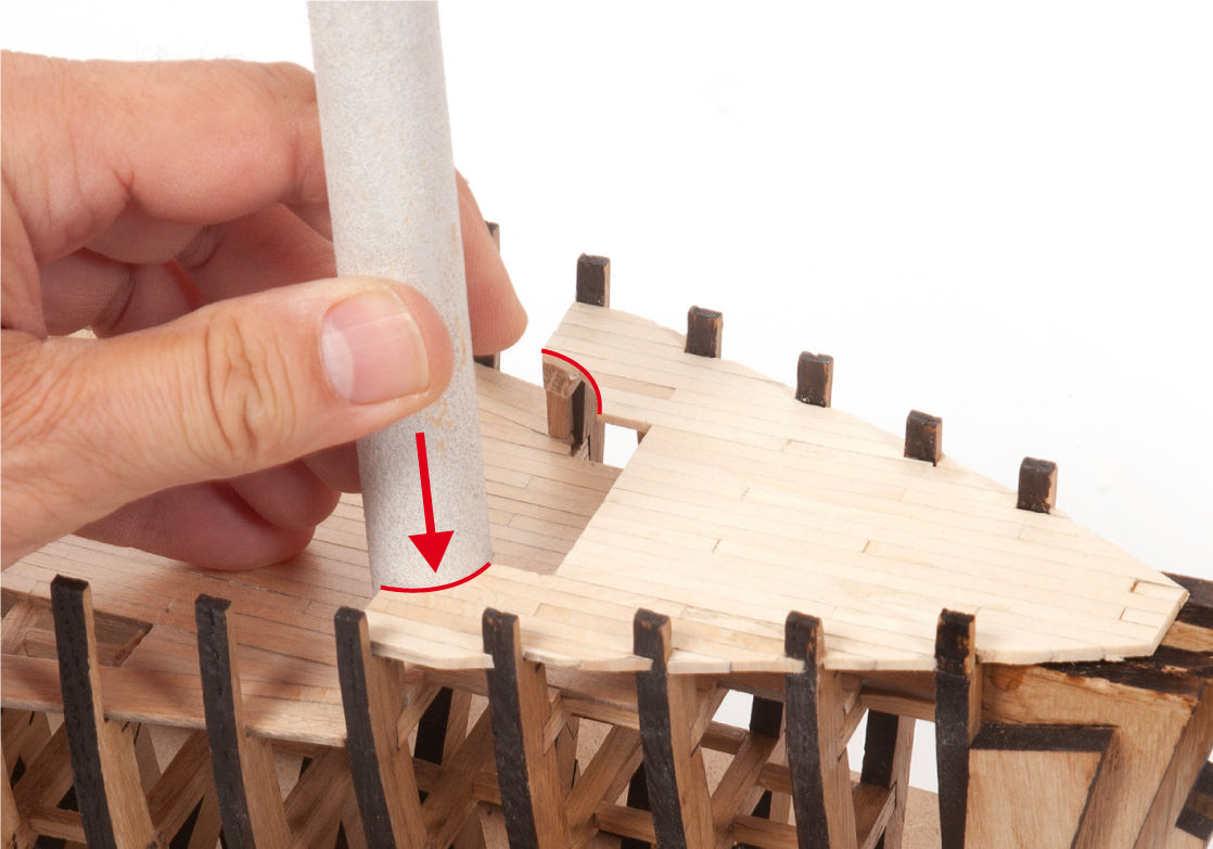
Step 18
Use rolled sandpaper or a round file to smooth the curved cut-outs.
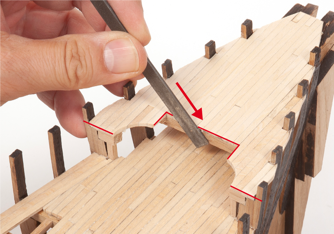
Step 19
Use a flat file to refine the deck cut-out.
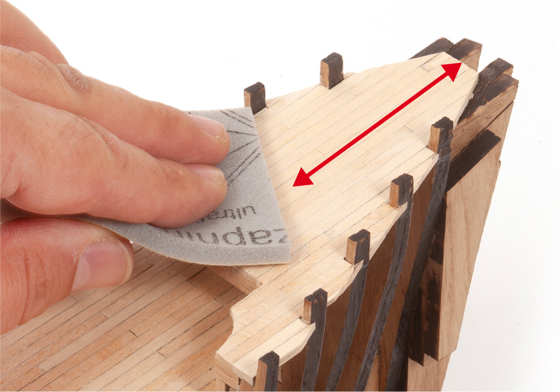
Step 20
Sand the forecastle deck planking with a fine-grit sanding sponge.
Step 1
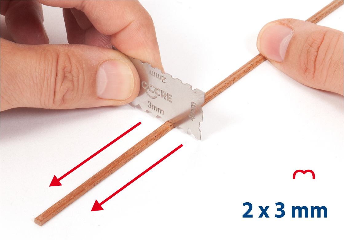
Use a grooving tool on a 2 x 3 mm mahogany strip for parts 4.99 and 4.100 (see step 3).
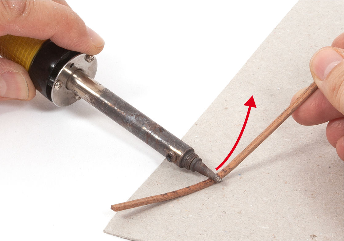
Step 2
Soak the strip in water to soften it. Use a soldering iron or plank bender to curve the strip.
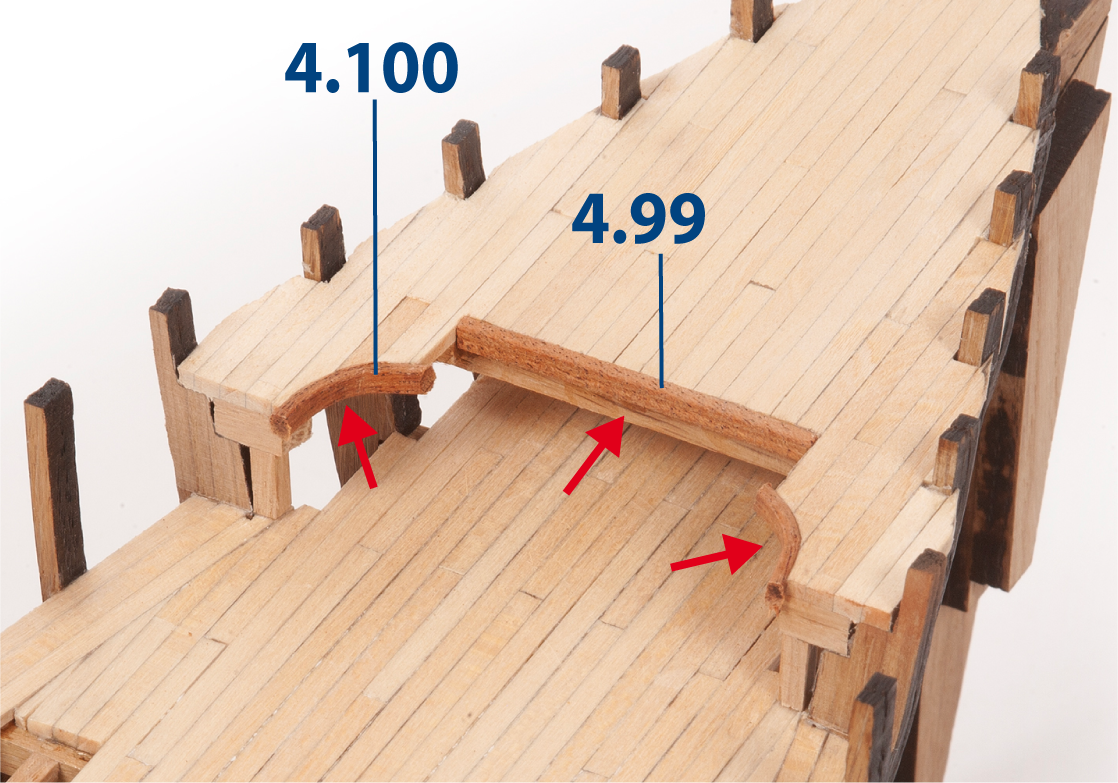
Step 3
Cut and glue part 4.99 (2 x 3 x 42 mm mahogany). Then cut and glue parts 4.100 (2 x 3 x 15 mm mahogany), following the deck curves.
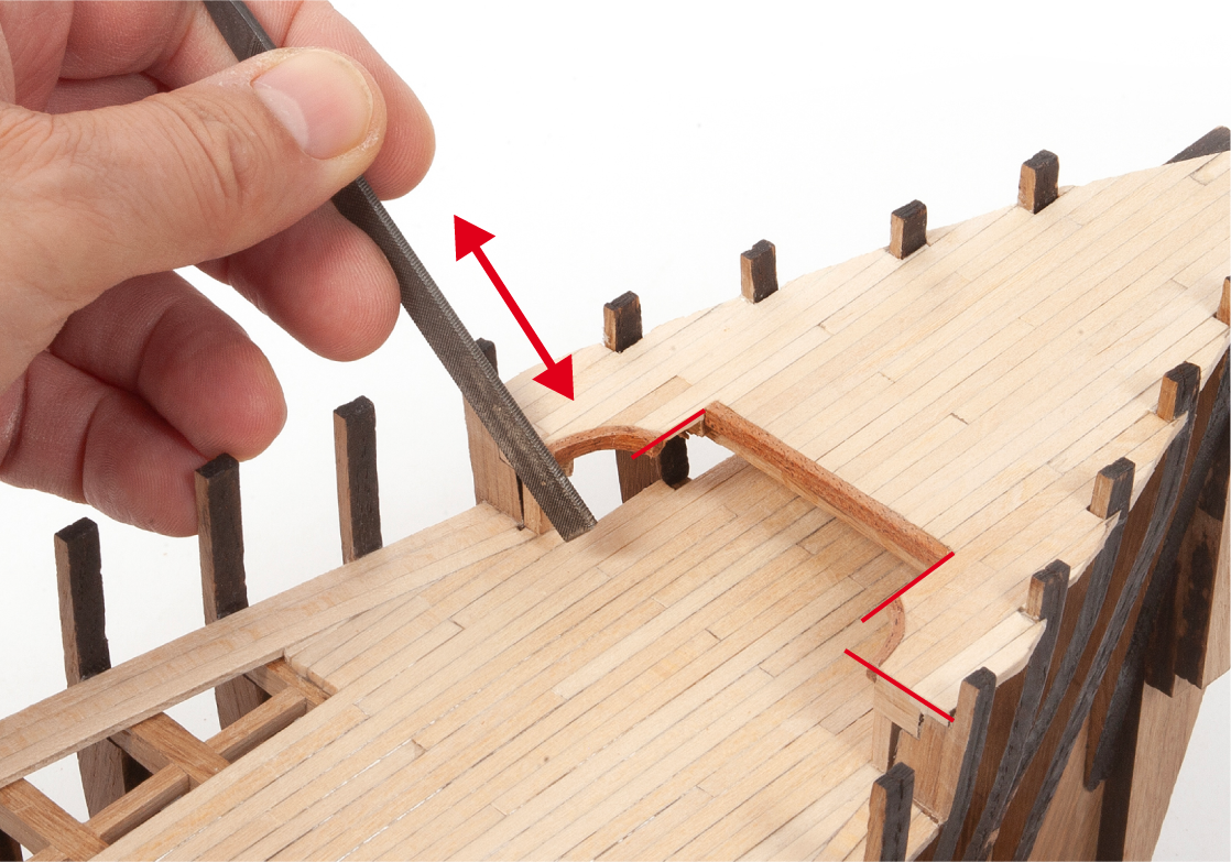
Step 4
File the ends of the parts so that they are flush with the deck planking.
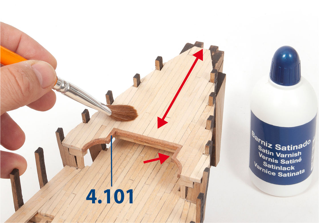
Step 5
Cut and glue parts 4.101 (2 x 3 x 12 mm mahogany). Then sand and varnish the added parts.
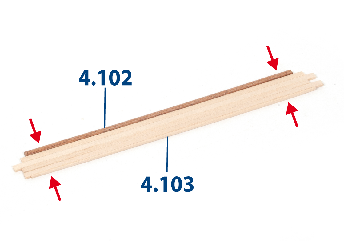
Step 6
Cut parts 4.102 (2 x 3 x 122 mm mahogany) and 4.103 (2 x 3 x 122 mm lime wood), then glue them together.
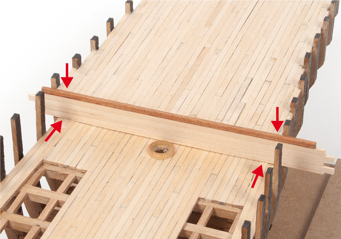
Step 7
Glue the assembly against the frame and deck, as shown.
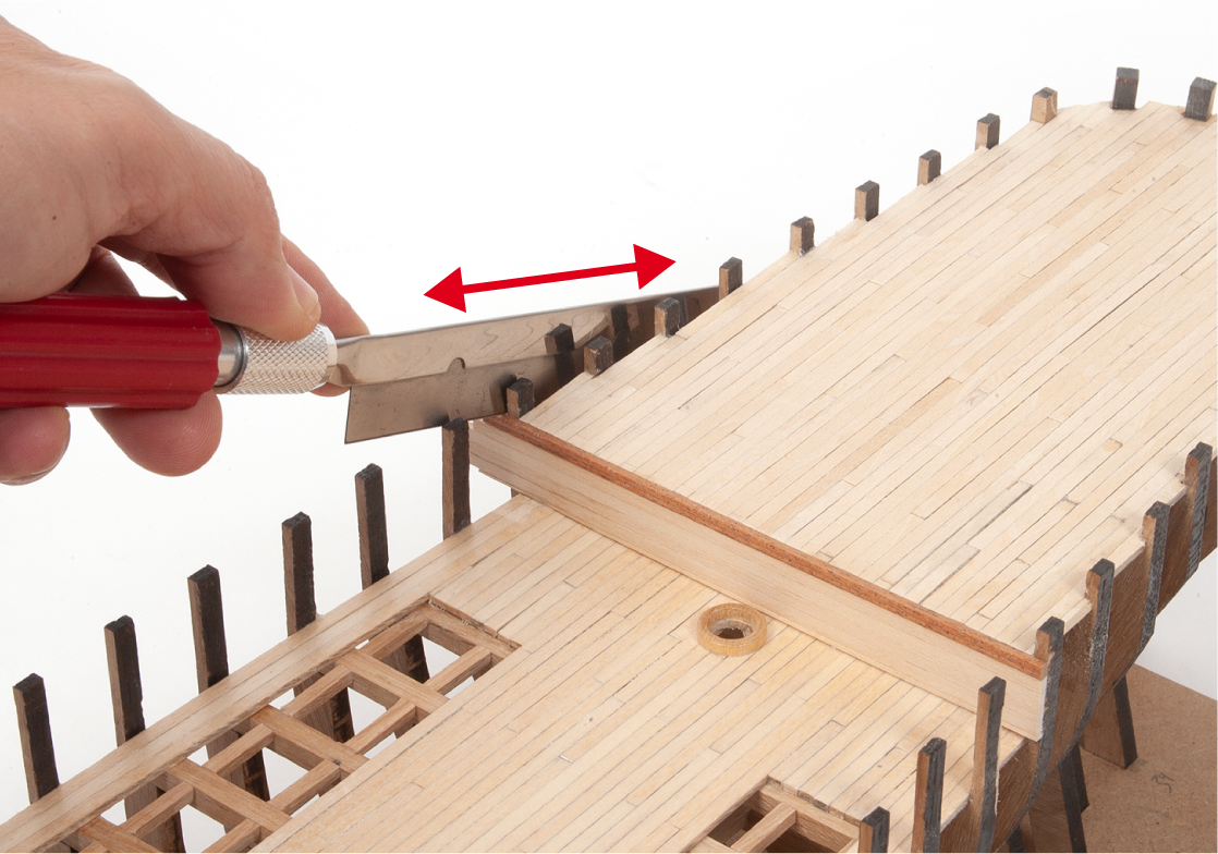
Step 8
Trim the excess planking flush with the outside of the frame.
Step 9
Sand and varnish the added parts on the poop deck.
Step 10
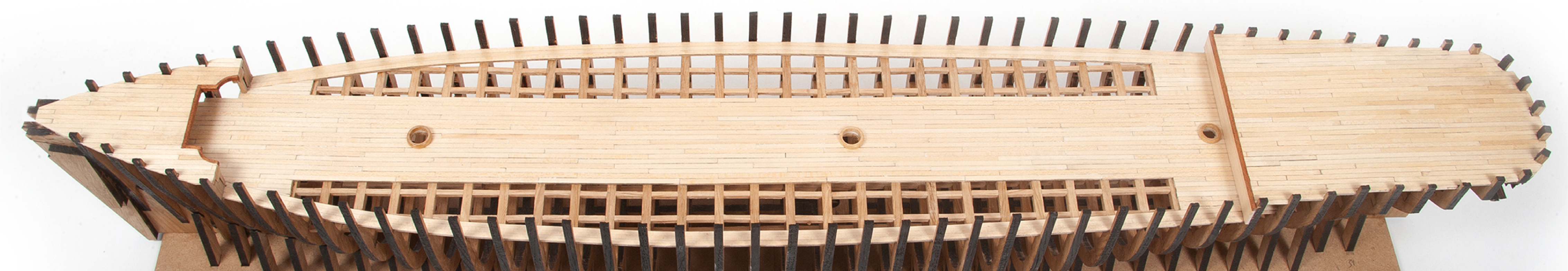
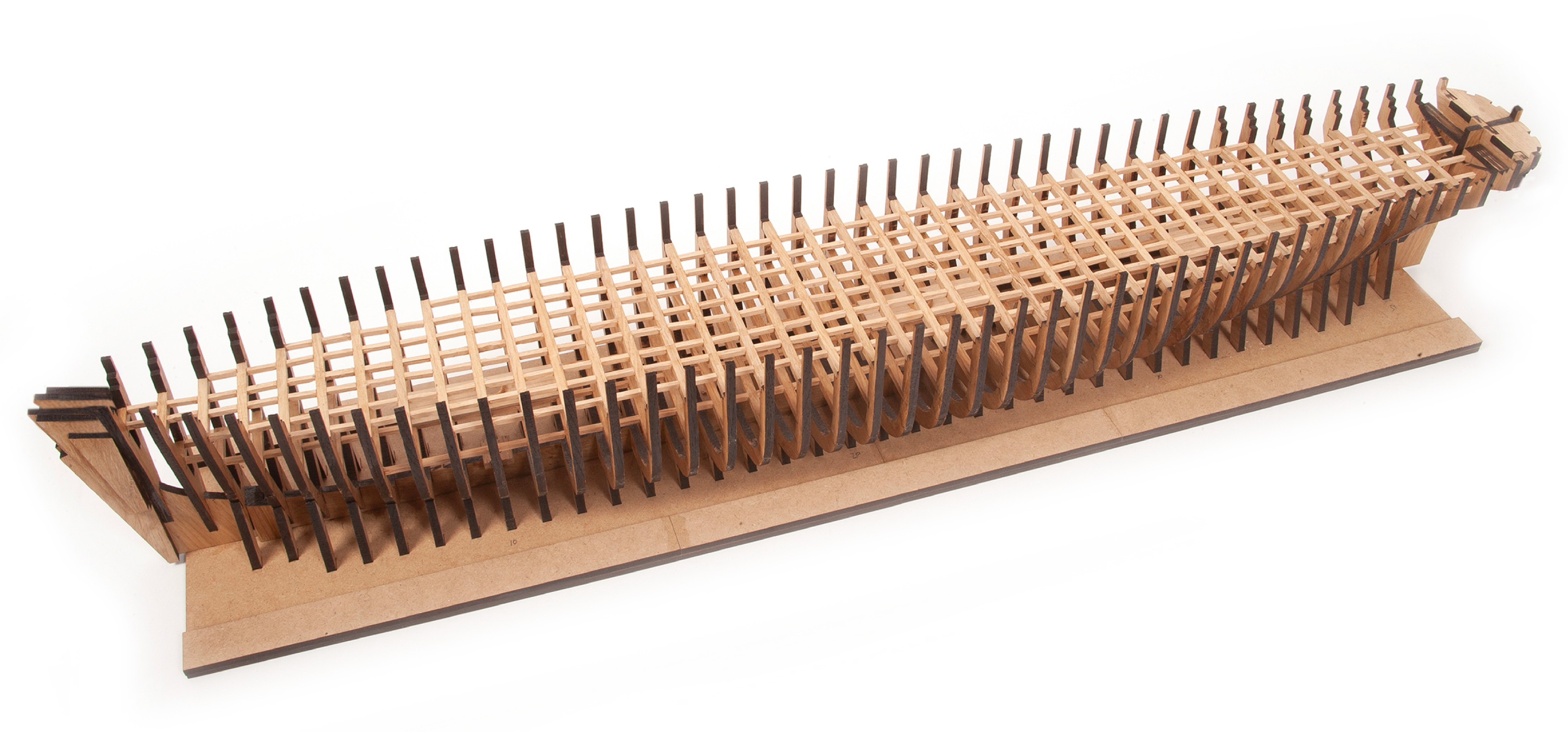
This image shows the appearance of the hull at the end of this stage.